Article

B2 NiAl Coatings Alloyed with Rare Earth Element Y: A First-Principles Study

1
School of Physics and Electronic Information, Huaibei Normal University, Huaibei 235000, China
2
State Owned Assets and Laboratory Management Division, Huaibei Normal University, Huaibei 235000, China
*
Author to whom correspondence should be addressed.
Coatings 2025, 15(6), 671; https://doi.org/10.3390/coatings15060671
Submission received: 6 April 2025 / Revised: 29 May 2025 / Accepted: 29 May 2025 / Published: 31 May 2025

Abstract

NiAl coatings are critical for protecting components in high-temperature environments. In order to improve the mechanical properties of NiAl coatings, in this study, the elastic and electronic properties of NiAl coatings alloyed with different contents of rare earth element (REE) Y were investigated by using the density functional theory (DFT). It was found that NiAl alloys with 3.125 at.% of Y exhibited higher hardness, while those with 6.25 at.% of Y showed better ductility. This phenomenon is explained by population analysis, which reveals that the covalency of Ni-Ni and Al-Al bonds is stronger in Ni15YAl16 than in Ni7YA8, whereas Ni-Al bonds exhibit stronger covalency in Ni7YAl8. Additionally, the ionicity of Y-Al bonds is higher in Ni7YAl8 than in Ni15YAl16. These results deepen our understanding of how rare earth elements modify the mechanical properties of NiAl alloys, thereby providing a theoretical basis for further exploration of their strengthening mechanisms.

1. Introduction

In extreme environments like gas turbines, aerospace engines, and power generation systems—where oxidation, thermal cycling, and mechanical degradation shorten material lifetimes—high-temperature coatings are essential for protecting metallic components. Among these protective systems, NiAl intermetallic coatings have emerged as a promising solution due to their unique combination of a high melting temperature, low density, high thermal conductivity, favorable stiffness, good oxidation resistance, and metal-like electrical conductivity. However, the application of NiAl coatings is restricted for its brittle fracture and low tensile ductility at room temperature [1].
Recent advancements in deposition techniques, compositional engineering, and computational modeling have revitalized interest in NiAl coatings. Innovations such as additive manufacturing and magnetron sputtering now enable precise control over coating microstructure and stoichiometry, while alloying with reactive elements has significantly enhanced their mechanical performance [2,3,4,5,6,7,8,9].
Due to the B2 structure of NiAl, REE additions usually exhibit certain site preferences [10,11]. Although this cannot alter the crystal structure of NiAl, the local electronic structure may be modified due to the differences in the electronic nature of REEs, Al, and Ni. Guo et al. [12] studied the effects of Y on the microstructure and mechanical properties of cast NiAl-28Cr-5.5Mo-0.5Hf alloy. The results showed that the microstructure of Y-doped alloys is gradually refined with Y addition, and that the appropriate Y addition improves the compressive ductility and yield strength at room temperature.
First-principles calculations based on the density functional theory (DFT) have been widely applied to study NiAl intermetallic compounds in recent years, mainly focusing on structural stability, oxidation behavior, and defect structures [13,14,15]. We have also systematically investigated the effects of doping Sc, Y, La, and Nd (6.25 at.%) on NiAl [16]. However, studies on NiAl doped with REEs at different concentrations remain scarce. Influenced by the solid solubility of Y in NiAl, generally, when the doping concentration of Y is too high, it cannot be ensured that all Y enters the grain interior. However, through some special experimental methods such as spark plasma sintering and laser remelting (non-equilibrium processes), NiAl with a higher solid solubility of Y may be obtained. Therefore, studying different Y doping concentrations aims to reveal their influence trends in the mechanical properties of NiAl and provide explanations from the electron structure level, which is helpful for understanding the compositional optimization of NiAl + Y alloys.
In this study, a first-principles approach is used to calculate the elastic and electronic properties of NiAl alloyed with different Y concentrations, aiming to illuminate the intrinsic effect of Y on NiAl at the atomic and electronic levels as a complement to experimental results.

2. Computational Method

The DFT is the most widely used framework in first-principles calculations, rooted in the Hohenberg–Kohn theorems and the Kohn–Sham equations. In this work, ultrasoft pseudopotentials [17] were employed in the CASTEP code (Cambridge Sequential Total Energy Package, BIOVIA Materials Studio CASTEP 2019), which utilizes plane wave pseudopotential to perform first-principles quantum mechanics calculations. Generalized gradient approximation (GGA) described by Perdew et al. [18] was adopted as the exchange-correlation functional for all elements in the models.

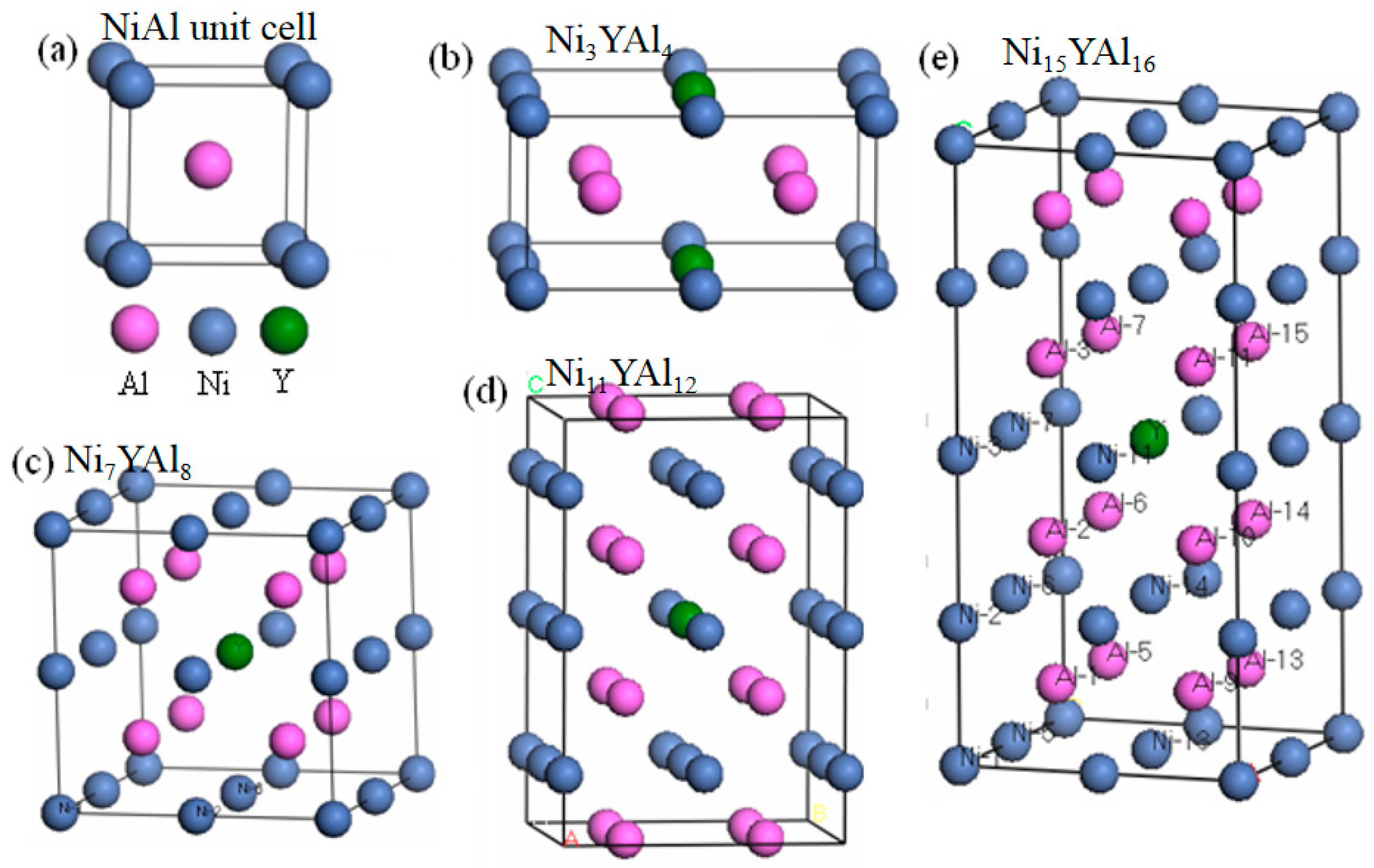
2.1. Model Structure

The unit cell of NiAl with the space group PM-3M and lattice constant of 2.9 Å is established. It is composed of one Ni atom at (0, 0, 0) and one Al atom at (1/2, 1/2, 1/2), as shown in Figure 1a. Since Y tends to occupy the Ni site in NiAl intermetallic compounds, the total energy and energy of site performance have been reported in previous studies [16,19]. We constructed an 8-atom 2 × 2 × 1 supercell for Ni3YAl4 (Figure 1b), a 16-atom 2 × 2 × 2 cubic B2 supercell for Ni7YAl8 (Figure 1c), a 24-atom 2 × 2 × 3 supercell for Ni11YAl12 (Figure 1d), and a 32-atom 2 × 2 × 4 supercell for Ni15YAl16 (Figure 1e). The Y atom was located at the center (0.5, 0.5, 0.5) of each supercell, ensuring that the Y-Al (Ni) pair was placed as nearest neighbors. Consequently, a pure NiAl B2 cell and NiAl supercells containing 12.5, 6.25, 4.167, and 3.125 at.% of Y were constructed. Y atoms were presumed to be in the ordered lattice of NiAl.

2.2. DFT Parameterization

The values of the kinetic energy cutoff (Ecut) and the k-points number increased until the calculated energy converged within the required tolerance. Here, Ecut determines the number of plane waves, and the k-points number determines the sampling of the irreducible wedge of the Brillouin zone. Ecut is set to 350 eV and the k point is set to 4 × 4 × 4 for Ni7YAl8 (other models are set to 4 × 4 × 2) with a regular Monkhorst–Pack scheme.

2.3. Convergence Criteria

In the self-consistent field (SCF) calculation, the Pulay scheme of density mixing [20] was adopted. The calculation of the elastic constants and the electronic structure are followed by cell optimization with a convergence tolerance energy of 5.0 × 10⁻⁶ eV atom−1, a maximum displacement of 5.0 × 10⁻⁴ Å, and a maximum force of 0.01 eVÅ−1.

3. Results and Discussions

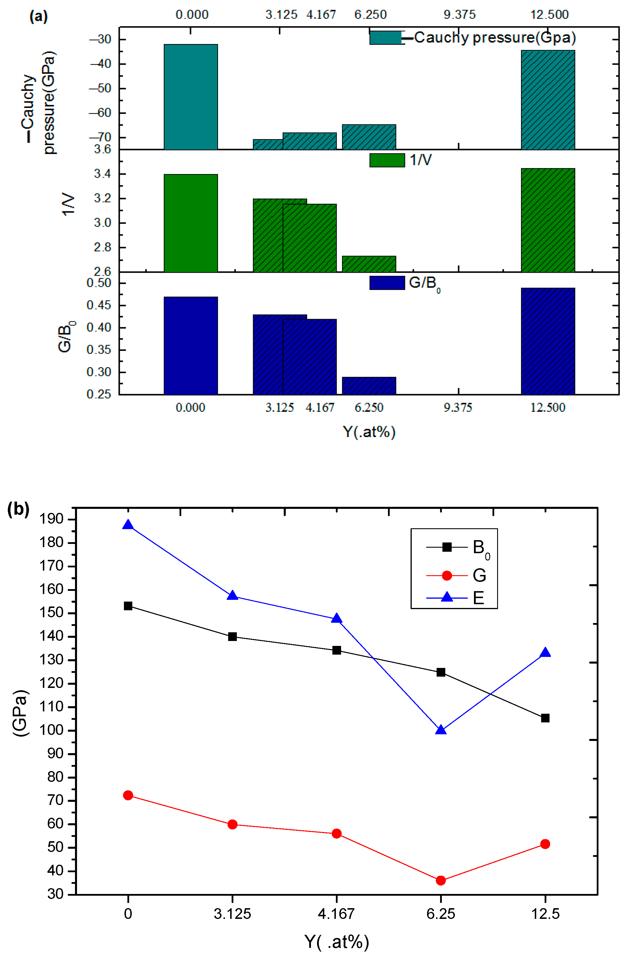
3.1. Elastic Properties

The elements Cij of the elasticity tensor are used to describe the elastic properties of single crystals. One condition for the mechanical stability of a structure is that its strain energy must be positive against any homogeneous elastic deformation. The mechanical stability criteria in cubic crystals are as follows [21,22]:
C11 − C12 > 0; C44 > 0; C11 + 2 C12 > 0
Since C11, C12, and C44 comprise the complete set of elastic constants for a cubic system, the bulk modulus B0′, the shear modulus G′, the Young’s modulus E, and the Poisson’s ratio ν can be calculated using the following Equations (1)–(4) [23]:
B0′ = (C11 + 2 C12)/3
G′ = (3 C44 + C11 − C12)/5
E = 9 B0G/(3 B0 + G)
ν = (1 − E/3 B0)/2
B0″ = (2 C11 + C33 + 2 C12 + 4 C13)/9
G″ = (2 C11 + C33 − C12 − 2 C13 + 6 C44 + 3 C66)/15
For tetragonal crystals, there are six independent elastic constants, usually referred to as C11, C12, C13, C33, C44, and C66. The requirement for mechanical stability leads to the following restrictions on its elastic constants [24]:
C11 − C12 > 0,   C11 + C33 – 2 C13 > 0
C11 > 0, C33 > 0, C44 > 0, C66 > 0
2 C11 + C33 + 2 C12 + 4 C13 > 0
The bulk modulus B0″and shear modulus G″ were calculated using Equation (5) and (6), respectively, while the Young’s modulus E and the Poisson’s ratio ν were derived from Equations (3) and (4), which are applicable to tetragonal crystals. The Cauchy pressures for cubic crystals and tetragonal crystals are defined as (C12 − C44) [25] and (C12 − C66) [26], respectively. Negative Cauchy pressures are presented here for ease of comparison. In Table 1, the calculated elastic constants indicate that only the models with 0 and 12.5 at.% of Y satisfy the mechanical stability criterion “C11 − C12 > 0”, while the other compositions are mechanically unstable. Despite this, these unstable models are still analyzed below, because their stability is determined by multiple conditions, and subsequent discussions remain relevant for understanding the compositional trends.
In Figure 2a, the negative Cauchy pressures, 1/v and G/B0, are calculated and plotted together as a function of increasing the Y content in NiAl. The Cauchy pressure serves as a criterion for evaluating ductility and brittleness: generally, ductile materials exhibit positive values, while brittle materials show negative values [27]. Figure 2a shows the negative Cauchy pressure for easy to compare, smaller negative Cauchy pressures, representing relatively more ductile materials. Compared to pure NiAl, the negative Cauchy pressure of the 12.5 at.% of Y-doped NiAl does not decrease significantly. In contrast, when the Y content is 3.125, 4.167, and 6.25 at.%, the negative Cauchy pressures are much lower, suggesting a substantial improvement in the ductility of these alloys.
Poisson’s ratio reflects the stability of a crystal against shear. This ratio can formally take values between −1 and 0.5; a smaller Poisson’s ratio leading to the more brittle behavior of materials. In other words, the smaller the reciprocal of Poisson’s ratio 1/v, the more ductile the materials are. Therefore, when the content of Y in NiAl is 12.5 at.%, the reciprocal of Poisson’s ratio increases compared with pure NiAl, and the other three different contents of Y reduce the reciprocal of Poisson’s ratio of each system to varying degrees. Among them, the system containing 6.25 at.% of Y exhibits a lower reciprocal of Poisson’s ratio, so this system is more ductile.
To predict the brittle or ductile behavior of solids, a simple relationship that also empirically linked the plastic properties of metals with their elastic modulus using G/B0 has been proposed by Pugh [28]. If G/B0 < 0.5, the material behaves in a ductile manner, and otherwise, it behaves in a brittle manner. In Figure 2a, G/B0 behaves in the same trend as 1/v. Hence, 6.25 at.% of Y gives the system the largest ductility.
Figure 2b shows the curves of Young’s modulus E, shear modulus G, and bulk modulus B0. It is generally believed that the hardness of materials can be related to their elastic modulus, such as the Young’s modulus E and the shear modulus G [29]. Although the relationships between hardness and the modulus are not identical for different materials, the general trend is, the larger the modulus, the harder the material. Therefore, the calculated Young’s modulus and shear modulus can be used as general guidance for the selection of materials.
The bulk modulus B0 represents the resistance to volume change and is related to the overall atomic binding properties in a material. From Figure 2b, it can be seen that E and G follow a similar trend. From the increasing amount of Y, Young’s modulus E and the shear modulus G show a similar trend of a decrease first and then an increase, and the turning point is at 6.25. When adding 3.125 at.% of Y into NiAl, the system shows the highest hardness. From B0, it can be concluded that adding Y into NiAl makes the bond strength of the system decrease.

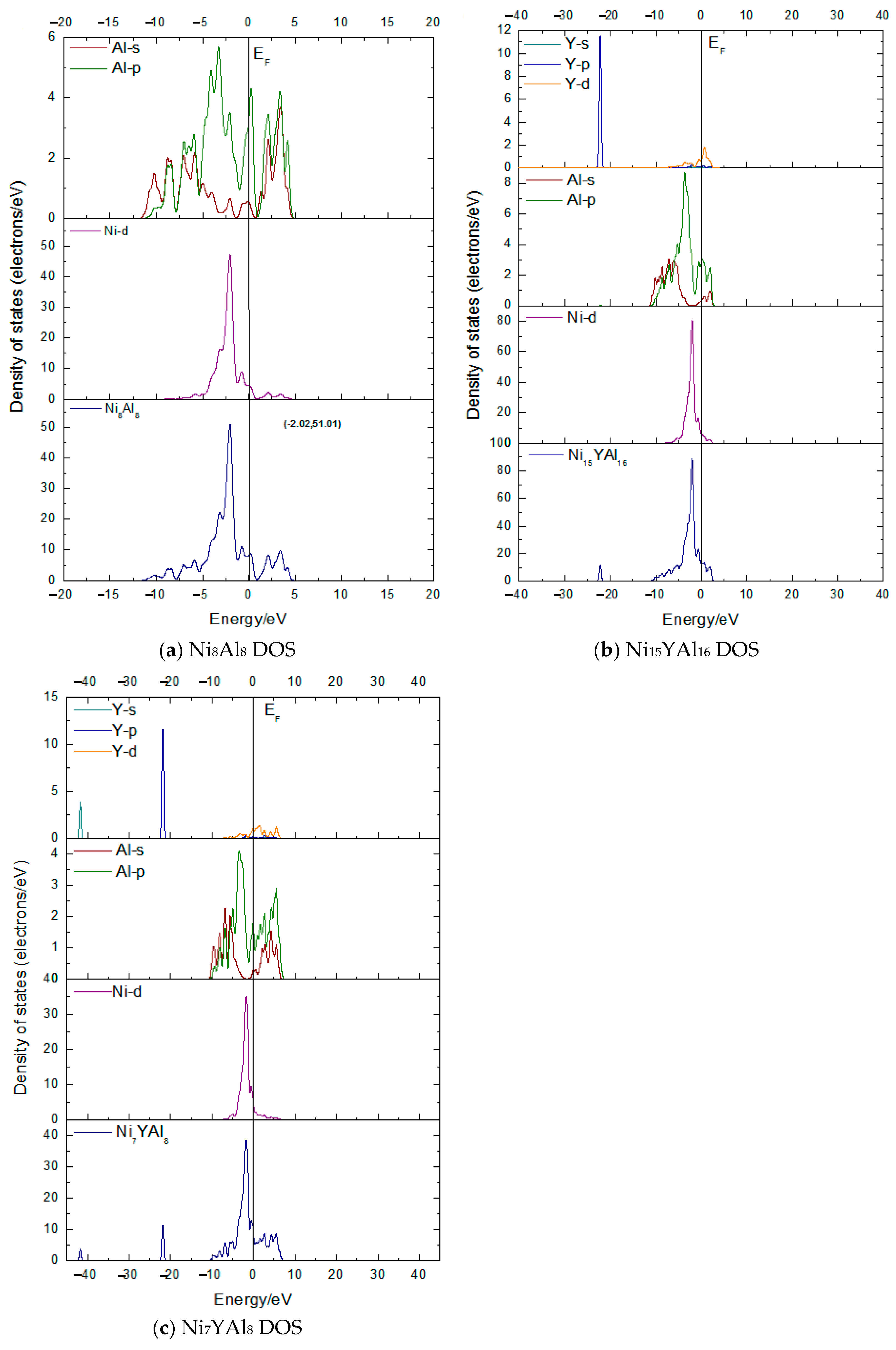
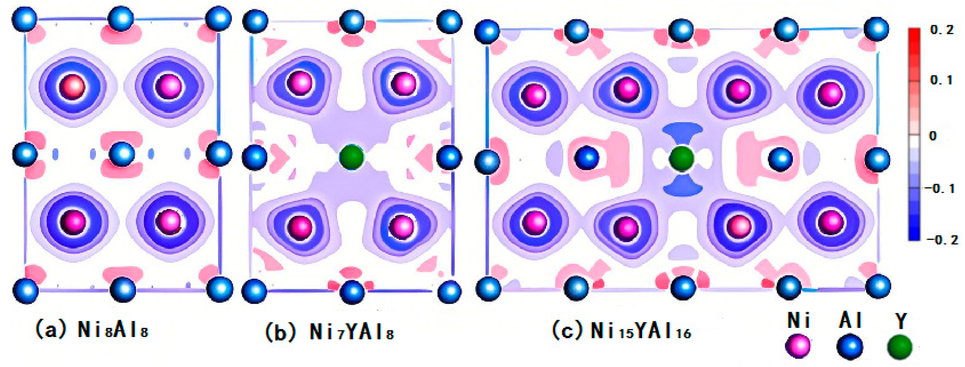
3.2. Density of States (DOSs) and Charge Density Contours

As discussed above, NiAl with 3.125 at.% and 6.25 at.% of Y demonstrate higher hardness and better ductility, respectively. We compared NiAl with the two systems— Ni15YAl16 and Ni7YAl8—in Figure 3 and Figure 4, in order to know the effect of Y, especially the content of Y on hardness and the ductility of NiAl in the DOSs as well as the charge density difference.
The dominant feature of the Ni8Al8 DOS is the presence of sharp peaks contributed by the d orbitals of Ni, which hybridize weakly with other orbitals, as shown in Figure 3a. The DOSs of Ni15YAl16 containing 3.125 at.% of Y and Ni7YAl8 containing 6.25 at.% of Y are shown in Figure 3b,c. Compared to Ni8Al8, the DOSs of Ni15YAl16 and Ni7YAl8 all add two sharp peaks around −22 eV and −42 eV, which are mainly due to the contribution of the s and p orbitals of Y. Near the Fermi level, the main peaks in Ni7YAl8 and Ni15YAl16 show a clear difference from Ni8Al8. The peak in Ni7YAl8 is lower and its energy span is broader, while Ni15YAl16 contrasts this. So, the delocalization is stronger by adding 6.25 at.% of Y into NiAl, while 3.125 at.% of Y just decreases the delocalization of the system.
Figure 4 shows the (110) plane charge density difference contours of Ni8Al8, Ni7YAl8, and Ni15YAl16. The blue regions represent the depletion (decrease) of electronic charge, while the red area represents the accumulation (increase) of electronic charge. Contours start from ±0.2, and increase successively by a factor of 0.025. Compared with the Ni8Al8 contours, we can obtain the information that, after replacing Ni with Y, the charge accumulation at Ni sites, which are the nearest neighbors of Y, indicates great bonding between Y and Ni in Ni15YAl16, and the bonding charge depletion between Y and its nearest neighbor Al in Ni7YAl8 and Ni15YAl16 is also quite evident. So, Y exists in the form of Y-Al bonds (in Ni7YAl8) or Y-Al/Y-Ni bonds (in Ni15YAl16). As for other types of bonding, even the covalent or ionic nature of the bonds, the limitation of the (110) plane charge density difference contours will be discussed in Section 3.3.

3.3. Population Analysis

Bond populations indicate the overlap degree of electron clouds of two bonding atoms and can be used to access the covalent or ionic nature of a chemical bond. For bond populations, the lowest and highest values imply that the chemical bond exhibits strong ionicity and covalency, respectively.

3.3.1. Ni-Al Bonds

In Table 2 and Table 3, the bond populations of Ni-Al in Ni15YAl16 and Ni7YAl8 are shown. Because of the symmetry of the super cell, the Ni-Al bonds formed by the Ni atoms (Ni1, Ni2, Ni3, Ni5, Ni6, Ni7, and Ni14) at different positions of the lower half of the super cell, the Al1 atom in the lowest layer, and the Al2 atom in the lower layer delegate all the Ni-Al bonds in Ni15YAl16.
Every Ni atom in Ni16Al16 is bonded with an Al atom, which is in the upper and lower layers of Ni, and all populations of Ni-Al bonds are the same (that is Population = 0.16, Length = 2.51147 Å, p = 0.064/Å). In Ni15YAl16, compared with Ni16Al16, because the Al2 atom is near the Y atom, most of the p values of Ni-Al bonds consisting of Al2 atoms increased, while most of the p values of Ni-Al bonds consisting of Al1 atoms decreased. The total increase in magnitude exceeds the decrease. So, on the whole, the covalency of Ni-Al bonds is enhanced in Ni15YAl16.
In Ni8Al8, three Ni atoms at the corner, on the edge, and the face could represent every situation of Ni atoms; the population values of these Ni-Al bonds are the same (Population = 0.14, Length = 2.51147 Å, p = 0.056/Å). In Ni7YAl8, every Ni atom is bonded with eight Al atoms, respectively. Because of the symmetry of the atom position, Ni1, Ni2, and Ni6 delegate all the Ni atoms in Ni7YAl8. In comparison with Ni8Al8, we found that with Y atoms, the populations of Ni-Al bonds in Ni7YAl8 increased to varying degrees.

3.3.2. Ni-Ni Bonds and Al-Al Bonds

In Table 4, Table 5, Table 6 and Table 7, the Ni-Ni bonds and Al-Al bonds are shown. In Ni15YAl16, similarly, Ni1, Ni2, Ni3, Ni5, Ni6, Ni7, Ni13, Ni14, Al1, Al5, Al9, Al13, Al2, Al6, Al10, and Al14 are chosen as research objects. In Ni16Al16, the populations of any two adjacent Ni atoms (and two Al atoms) along the axis direction are the same.
We can see that compared with Ni16Al16, the Ni15YAl16, except for the population of Ni-Ni bonds along the X-direction, decreased to differing degrees; along the Y- and Z-directions, the population shows an increasing trend near the Y atom and a decreasing trend far away from the Y atom.
For the Al-Al bonds, the population of Al-Al bonds increased to differing degrees, and the more close to the Y atom, the more the value of the population increased, while the population along the Z-direction decreased. In general, the population increased more than decreased, hence, the covalency of Al-Al bonds increased.
In Ni7YAl8, there are no Ni-Ni bonds. Every Ni atom is bonded with eight Al atoms. Because of the symmetry of the atom position, Ni1, Ni2, and Ni6 delegate all the Ni atoms in Ni7YAl8. As for Al-Al bonds, all the Al atoms are bonded with their three nearest neighbor Al atoms, and the whole population of Al-Al bonds are the same. In Ni8Al8, three Ni atoms at the corner, on the edge, and the face are considered; the population values of these Ni-Al bonds are quite similar. Al-Al bonds (or Ni-Ni bonds) are formed by every single Al atom (or Ni atom) and its three nearest neighbor Ni atoms (or Al atoms).
When compared to Ni8Al8, the populations of Al-Al bonds in Ni7YAl8 increase to varying degrees. That is to say, their covalent character enhanced to varying degrees. However, Ni is mainly bonded with Y, which is discussed in the following part.
In Formulas (7) and (8), P′ and P″ represent the average changes in the charge populations of the unit bond length in Ni15YAl16 and Ni7YAl8, respectively. Larger values of P′ and P″ indicate a higher degree of covalency or ionicity in the system.
P = [ m = 1 m P N i 15 Y A l 16 ( m ) P N i 16 A l 16 ] / m
P = [ n = 1 n P N i 7 Y A l 8 ( n ) P N i 8 A l 8 ] / n
(m, n, numbers of Ni-Al bonds chosen in Ni15YAl16 and Ni7YAl8, P Ni16Al16 = 0.064/Å PNi8Al8 = 0.056/Å).
For Ni-Al bonds, P′ = 0.005/Å and P″ = 0.019/Å, so, the covalency of Ni-Al bonds in Ni7YAl8 enhanced greatly. Ni-Ni bonds are absent in Ni7YAl8, while in Ni15YAl16, they demonstrate higher covalency (P′ = 0.008/Å). Regarding the Al-Al bonds, P′ = 0.0240/Å and P″ = 0.0239/Å; hence, the covalency increased in Ni15YAl16.

3.3.3. Y-Ni Bonds and Y-Al Bonds

In this section, Y bonding with Ni or Al is discussed. In Ni15YAl16, Y is bonded with its nearest two Ni atoms (Population = −0.49, Length = 2.90 Å, p = −0.17/Å) and eight Al atoms(Population = −0.30, Length = 2.81 Å, p = −0.11/Å). In Ni7YAl8, Y is only bonded with its eight neighbor Al atoms (Population = −0.33, Length = 2.78 Å, p = −0.12/Å). Therefore, Y exists as Y-Al bonds in Ni7YAl8, as Y-Al, and Y-Ni bonds in Ni15YAl16. Compared with the values of population, we find that the ionicity in Ni7YAl8 is higher than in Ni15YAl16, and that the ionicity of Y-Ni bonds is higher than Y-Al bonds in Ni15YAl16.
Therefore, it can be concluded that after adding Y, the covalency of both Ni-Al bonds and Al-Al bonds is enhanced in Ni15YAl16 and Ni7YAl8; in Ni15YAl16, the covalency of Ni-Ni bonds and Al-Al bonds is stronger than in Ni7YAl8, while the covalency of Ni- Al bonds in Ni7YAl8 is stronger than in Ni15YAl16. Y exists in the form of Y-Al bonds (in Ni7YAl8) or Y-Al/Y-Ni bonds (in Ni15YAl16), and the ionicity of Y-Al bonds in Ni7YAl8 is stronger than in Ni15YAl16.

4. Conclusions

Ab initio DFT calculations have been performed to study the effects of different contents of Y on the elastic and electronic properties of NiAl. In general, the following conclusions are obtained: (i) NiAl with the content of Y as 3.125 at.% and 6.25 at.% exhibits higher hardness and better ductility, respectively. (ii) The delocalization is stronger by adding 6.25 at.% of Y into NiAl, while adding 3.125 at.% of Y just decreases the delocalization. (iii) The covalency of Ni-Ni bonds and Al-Al bonds is stronger in Ni15YAl16 than in Ni7YAl8, while the covalency of Ni-Al bonds in Ni7YAl8 is stronger than in Ni15YAl16. (iv) The ionicity of Y-Al bonds in Ni7YAl8 is stronger than in Ni15YAl16.
From the practical point of view, adding REE Y to NiAl is highly recommended, and its content is best controlled below 4.167 at.%. Perhaps, gradient doping design (high Y amount on the surface to enhance ductility and low Y amount inside to maintain hardness) can be used to achieve strong toughness and synergistic optimization.
Constrained by the computing power of the computer, the content of Y in this work only reaches 3.125 at.%, which should be even lower in practical applications. There is no corresponding experimental verification; this work is only supported by the experimental data of other researchers. It is recommended that future work should continue to reduce the content of Y, fully consider the solubility of Y, and be supplemented by experimental verification.

Author Contributions

Conceptualization, J.H.; Software, L.Y.; Data curation, J.Z.; Writing—original draft, J.H. All authors have read and agreed to the published version of the manuscript.

Funding

This work was supported by the Anhui Province Quality Engineering Project (No. 2022zygzts100), MOE Industry-University Cooperation Joint Talent Cultivation Project (No. 230805078245255), and Quality Engineering Project of Huaibei Normal University (No. 2022xxqhz005).

Institutional Review Board Statement

Not applicable.

Informed Consent Statement

Not applicable.

Data Availability Statement

The data are contained within the article.

Conflicts of Interest

The authors declare no conflicts of interest or personal relationships that could have appeared to influence the work reported in this paper.

Abbreviations

The following abbreviations are used in this manuscript:
REERare earth element
DFTDensity functional theory
CASTEPCambridge Sequential Total Energy Package
GGAGeneralized gradient approximation
EcutKinetic energy cutoff
SCFSelf-consistent field

References

  1. Liu, C.T.; Stringer, J.; Mundy, J.N.; Horton, L.L.; Angelini, P. Ordered. Intermetallic Alloys: An Assessment. Intermetallics 1997, 5, 579–596. [Google Scholar] [CrossRef]
  2. Sun, Y.W.; Yuan, J.H.; Wang, M.; Wang, H.Y.; Chen, Z.Y.; Liu, X.Y.; Li, S.W.; Zhao, W.W.; Yang, J.Y. Enhanced tribological performance of NiAl-based composite coatings: Design of the composition in coatings by addition of Mo and Nanodiamond. Tribol. Int. 2025, 203, 110405. [Google Scholar] [CrossRef]
  3. Pesterev, E.; Yakovlev, E.; Pichugin, N.; Petrov, V.; Maznoy, A. Application of vacuum plasma techniques for preparation of Ni-Cr-Dy powders proposed as masteralloys for combustion synthesis of Ni-Al intermetallics. Vacuum 2025, 234, 114054. [Google Scholar] [CrossRef]
  4. Yu, Y.; Zhou, J.; Ren, S.; Wang, L.; Xin, B.; Cao, S. Tribological properties of laser cladding NiAl intermetallic compound coatings at elevated temperatures. Tribol. Int. 2016, 104, 321–327. [Google Scholar] [CrossRef]
  5. Song, Y.; Guo, Z.X.; Yang, R.; Li, D. First principles study of site substitution of ternary elements in NiAl. Acta Mater. 2001, 49, 1647–1654. [Google Scholar] [CrossRef]
  6. Bozzolo, G.; Noebe, R.D.; Honecy, F. Modeling of ternary element site substitution in NiAl. Intermetallics 2000, 8, 7–18. [Google Scholar] [CrossRef]
  7. Serrano, M.; Molina, A.; Guardian, R.; Pozo, A.D.; Verduzco, J.A.; Sedano, A. Synthesis and microstructure characterization of nanocrystalline NiAl compound with copper addition by mechanical alloying. MRS Adv. 2023, 8, 1182–1187. [Google Scholar] [CrossRef]
  8. Zhao, C.S.; Zhou, Y.H.; Zou, Z.H.; Luo, L.R.; Zhao, X.F.; Guo, F.W.; Xiao, P. Effect of alloyed Lu, Hf and Cr on the oxidation and spallation behavior of NiAl. Corros. Sci. 2017, 126, 334–343. [Google Scholar] [CrossRef]
  9. Barth, T.L.; Marquis, E.A. Effects of Minor Alloying Elements on Alumina Transformation During the Transient Oxidation of β-NiAl. Oxid. Met. 2021, 95, 293–309. [Google Scholar] [CrossRef]
  10. Jiang, C. Site preference of transition-metal elements in B2 NiAl: A comprehensive study. Acta Mater. 2007, 55, 4799–4806. [Google Scholar] [CrossRef]
  11. Frommeyer, G.; Fischer, R.; Deges, J.; Rablbauer, R.; Schneider, A. APFIM investigations on site occupancies of the ternary alloying elements Cr, Fe and Re in NiAl. Ultramicroscopy 2004, 101, 139–148. [Google Scholar] [CrossRef] [PubMed]
  12. Guo, J.T.; Huai, K.W.; Gao, Q.; Ren, W.L.; Li, G.S. Effects of rare earth elements on the microstructure and mechanical properties of NiAl-based eutectic alloy. Intermetallics 2007, 15, 727–733. [Google Scholar] [CrossRef]
  13. Zhang, Z.; Hu, C.C.; Chen, H.; He, J. Pinning effect of reactive elements on structural stability and adhesive strength of environmental sulfur segregation on Al2O3/NiAl interface. Scr. Mater. 2020, 188, 174–178. [Google Scholar] [CrossRef]
  14. Niu, X.F.; Huang, W.; Wang, B.J.; Wang, C.C.; Song, Z.L. Effects of Point Defects on Properties of B2 NiAl: A First-principles Study. Rare Met. Mater. Eng. 2018, 47, 2687–2692. [Google Scholar]
  15. Wang, X.L.; Cai, C.Y.; Zhou, G.W. First-principles study on the NiAl/Al2O3 interfacial segregation of Hf during the oxidation of Hf-modified NiAl. Appl. Surf. Sci. 2022, 578, 151917. [Google Scholar] [CrossRef]
  16. He, J.Q.; Wang, Y.; Yan, M.F.; Yang, Y.; Wang, L. First-principles study of NiAl microalloyed with Sc, Y, La and Nd. Comp. Mater. Sci. 2010, 50, 545–549. [Google Scholar] [CrossRef]
  17. Vanderbilt, D. Soft self-consistent pseudopotentials in a generalized eigenvalue formalism. Phys. Rev. B 1990, 41, 7892. [Google Scholar] [CrossRef]
  18. Perdew, J.P.; Chevary, J.A.; Vosko, S.H. Atoms, molecules, solids, and surfaces: Applications of the generalized gradient approximation for exchange and correlation. Phys. Rev. B 1992, 46, 6671–6687. [Google Scholar] [CrossRef]
  19. Zhang, C.L.; Han, P.D.; Li, J.M.; Chi, M.; Yan, L.Y.; Liu, Y.P.; Liu, X.G.; Xu, B.S. First-principles study of the mechanic properties of NiAl microalloyed by M (Y, Zr, Nb, Mo, Tc, Ru, Rh, Pd, Ag, Cd). J. Phys. D Appl. Phys. 2008, 41, 1–5. [Google Scholar]
  20. Hammer, B.; Hansen, L.B.; Nrskov, J.K. Improved adsorption energetics within density-functional theory using revised perdew-burke-ernzerhof functionals. Phys. Rev. B 1999, 59, 7413. [Google Scholar] [CrossRef]
  21. Nye, J.F. Physical Properties of Crystals; Oxford University Press: Oxford, UK, 1985. [Google Scholar]
  22. Karki, B.B.; Ackland, G.J.; Crain, J.; Phys, J. Elastic instabilities in crystals from ab initio stress—Strain relations. J. Phys. Condens. Matter 1997, 9, 8579–8589. [Google Scholar] [CrossRef]
  23. Rusovi, N.; Warlimont, H. The elastic behaviour of β2-NiAl alloys. Phys. Status Solidi (a) 1977, 44, 609–619. [Google Scholar] [CrossRef]
  24. Beckstein, O.; Klepeis, J.E.; Hart, G.L.W.; Pankratov, O. First principles elastic constants and electronic structure of α-Pt2Si and PtSi. Phys. Rev. B 2001, 63, 1–12. [Google Scholar] [CrossRef]
  25. Pettifor, D.G. Theoretical predictions of structure and related properties of intermetallics. Mater. Sci. Technol. 1992, 8, 345–349. [Google Scholar] [CrossRef]
  26. Born, M.; Huang, K. Dynamical Theory of Crystal Lattices; Oxford University Press: Oxford, UK, 1954. [Google Scholar]
  27. Johnson, R.A. Analytic nearest-neighbor model for fcc metals. Phys. Rev. B 1988, 37, 3924–3931. [Google Scholar] [CrossRef]
  28. Pugh, S.F. Relations between the elastic moduli and the plastic properties of polycrystalline pure metals. Philos. Mag. 1954, 45, 823–843. [Google Scholar] [CrossRef]
  29. Frantsevich, I.N.; Voronov, F.F.; Bokuta, S.A. Elastic Constants and Elastic Moduli of Metals and Insulators; Naukova Dumka: Kiev, Ukraine, 1983; pp. 60–180. [Google Scholar]
Figure 1. Models of (a) the unit cell of NiAl, (b) Ni3YAl4, (c) Ni7YAl8, (d) Ni11YAl12, and (e) Ni15YAl16.
Coatings 15 00671 g001
Figure 2. (a) The ratios of shear modulus to bulk modulus G/B0, negative Cauchy pressure parameters -(C12−C44), and the reciprocal of Poisson’s ratio 1/v. (b) The curves of Young’s modulus E, shear modulus G, and bulk modulus B0.
Coatings 15 00671 g002
Figure 3. DOSs: (a) Ni8Al8, (b) Ni15YAl16, and (c) Ni7YAl8.
Coatings 15 00671 g003
Figure 4. Charge density difference contours of (110) plane of (a) Ni8Al8, (b) Ni7YAl8, and (c) Ni15YAl16.
Coatings 15 00671 g004
Table 1. Elastic constants of (NiY) Al supercells with different Y concentrations (All values are in GPa).
Y(.at%)C11(GPa)C33(GPa)C44(GPa)C66(GPa)C12(GPa)C13(GPa)
0173.48173.48117.41117.41149.37149.37
3.125138.01174.3195.4793.44164.24120.27
4.167117.62165.2292.4096.48160.48121.64
6.2577.9377.9383.5483.54148.30148.30
12.5126.00138.5277.6165.1799.6489.34
Table 2. Charge populations of Ni-Al unit bond length in Ni15YAl16.
Bond
(Ni15YAl16)
PopulationLength
(Å)
p
(/Å)
Ni1–Al10.162.530.063
Ni2–Al10.152.480.060
Ni5–Al10.162.520.063
Ni14–Al10.162.590.062
Ni6–Al10.172.520.067
Ni2–Al20.182.460.073
Ni6–Al20.192.520.075
Ni7–Al20.192.710.070
Ni14–Al20.222.550.086
Ni3–Al20.162.600.06
Table 3. Charge populations of Ni-Al unit bond length in Ni7YAl8.
Bond
(Ni7YAl8)
PopulationLength
(Å)
p
(/Å)
Ni1–Al0.182.430.074
Ni2–Al0.182.550.071
Ni6–Al0.212.670.079
Table 4. Charge populations of Ni-Ni/Al-Al unit bond length in Ni15YAl16.
X-DirectionY-DirectionZ-Direction
Bond
(Ni15YAl16)
PopulationLength
(Å)
p
(/Å)
Bond
(Ni15YAl16)
PopulationLength
(Å)
p
(/Å)
Bond
(Ni15YAl16)
PopulationLength
(Å)
p
(/Å)
Ni5-Ni13−0.012.90−0.003Ni1-Ni5−0.012.90−0.003Ni1-Ni2−0.042.82−0.014
Ni6-Ni14−0.022.91−0.007Ni2-Ni60.042.900.014Ni5-Ni602.920
----Ni3-Ni70.182.900.062----
Al1-Al90.232.880.080Al1-Al50.232.880.080Al1-Al20.092.910.031
Al2-Al100.392.710.144Al2-Al60.392.710.144Al5-Al60.092.910.031
Al5-Al130.232.880.080Al9-Al130.232.880.080Al9-Al100.092.910.031
Al6-Al140.392.710.144Al10-Al140.392.710.144Al13-Al140.092.910.031
Table 5. Charge populations of Ni-Ni/Al-Al unit bond length in Ni16Al16.
X-DirectionY-DirectionZ-Direction
Bond
(Ni16Al16)
PopulationLength
(Å)
p
(/Å)
Bond
(Ni16Al16)
PopulationLength
(Å)
p
(/Å)
Bond
(Ni16Al16)
PopulationLength
(Å)
p
(/Å)
Ni-Ni02.900Ni-Ni02.900Ni-Ni−0.022.90−0.007
Al-Al0.212.900.072Al-Al0.212.900.072Al-Al0.112.900.038
Table 6. Charge populations of Ni-Ni/Al-Al unit bond length in Ni7YAl8.
X-directionY-DirectionZ-Direction
Bond
(Ni7YAl)8
PopulationLength
(Å)
p
/Å)
Bond
(Ni7YAl8)
PopulationLength
(Å)
p
(/Å)
Bond
(Ni7YAl8)
PopulationLength
(Å)
p
(/Å)
Al-Al0.282.810.100Al-Al0.282.810.100Al-Al0.282.810.100
Table 7. Charge populations of Ni-Ni/Al-Al unit bond length in Ni8Al8.
X-directionY-directionZ-direction
Bond
(Ni8Al8)
PopulationLength
(Å)
p
(/Å)
Bond
(Ni8Al8)
PopulationLength
(Å)
p
(/Å)
Bond
(Ni8Al8)
PopulationLength
(Å)
p
(/Å)
Ni-Ni−0.032.90−0.010Ni-Ni−0.032.90−0.010Ni-Ni−0.032.90−0.010
Al-Al0.222.900.076Al-Al0.222.900.076Al-Al0.222.900.076
Disclaimer/Publisher’s Note: The statements, opinions and data contained in all publications are solely those of the individual author(s) and contributor(s) and not of MDPI and/or the editor(s). MDPI and/or the editor(s) disclaim responsibility for any injury to people or property resulting from any ideas, methods, instructions or products referred to in the content.

