Article

Improved Adhesion of PTFE Surfaces via Low-Power DC Plasma and Fast Neutrals Flow

Department of Physical Electronics and Technology, Saint Petersburg Electrotechnical University “LETI”, ul. Professora Popova 5, 197022 St. Petersburg, Russia
*
Author to whom correspondence should be addressed.
Coatings 2025, 15(6), 644; https://doi.org/10.3390/coatings15060644
Submission received: 28 April 2025 / Revised: 20 May 2025 / Accepted: 23 May 2025 / Published: 26 May 2025
(This article belongs to the Special Issue Plasma Treatment for Coatings and Environmental Pollution Control)

Abstract

:
A method for enhancing the adhesion properties of polytetrafluoroethylene (PTFE) surfaces is presented. The approach employs a fast neutrals flow generated by a DC glow discharge plasma with a grid neutralizer. Low power levels (≈6 W) provided by the stable DC discharge prevent physical sputtering and surface damage, while strong UV radiation from pure argon promotes efficient defluorination. The choice of working gas composition, discharge parameters, and treatment duration was informed by plasma emission spectroscopy, water contact angle (WCA) measurements, and systematic optimization. The combined effect of low-energy neutral particles and UV radiation leads to a significant increase in surface energy to 82 mN/m and a reduction in WCA to 13°, confirming the effectiveness of the proposed method. Thanks to its simplicity, scalability, and reliability, the method holds significant potential for industrial applications.

1. Introduction

Polytetrafluoroethylene (PTFE), commonly known as Teflon, stands out as the most robust material within the fluoroolefin family, enjoying widespread applications across various industries such as mechanical engineering, electrical engineering, medicine, and the food sector [1,2]. However, PTFE’s inherently high anti-adhesive and hydrophobic properties pose significant challenges, making the development of methods to enhance PTFE adhesion a critical technological endeavor [3]. To tackle the challenge, the fluoropolymer’s surface needs to be modified by changing its morphology and composition [4]. Various techniques can achieve this, including direct chemical processing in gas (or liquid) phases, as well as physicochemical treatments involving corona discharge, ion beams, laser irradiation, ultraviolet light, and other similar approaches.
Since adhesion is fundamentally tied to the process of surface wetting, one straightforward method for studying wetting behavior involves measuring changes in the water contact angle (WCA) and then determining the corresponding surface energy values.
The primary industrial methods currently used for PTFE surface activation are direct chemical treatment and corona discharge treatment. Direct chemical treatment of PTFE surfaces [5,6,7] typically entails submerging samples in solutions containing metal–aromatic complexes based on alkali metals (such as Li, K, Na) combined with aromatic hydrocarbons (like naphthalene, diphenyl, anthracene, etc.) Nevertheless, this approach introduces several notable disadvantages. Firstly, using corrosive reagents may result in the unintentional deposition of alkali metal residues onto the surface, causing unpredictable alterations in the material’s electrical conductivity, wettability, and other key characteristics. Secondly, managing these reactive metals carries serious health and safety hazards. Moreover, during treatment, approximately 70% of the original active solution transforms into waste, necessitating disposal. The resultant spent solution, now laden with toxic compounds, ultimately enters industrial wastewater streams following neutralization procedures, exacerbating environmental contamination concerns [8]. Corona discharge treatment eliminates pollution problems. High-frequency power generates a corona between two electrodes—one at high potential and the other grounded—ionizing air in the gap and activating the material’s surface as it moves past [9,10,11]. The advantages of industrial methods include their relative ease of implementation, reliability, high processing speeds, and the ability to treat large surface areas. However, these methods fail to achieve a water contact angle (WCA) below 50°, driving the search for more effective solutions.
An alternative strategy employs glow-discharge plasma activation of the PTFE surface [12,13,14,15,16,17,18,19,20,21,22,23,24,25,26,27,28,29,30,31]. During plasma treatment, interactions among charged particles, neutral atoms, and surface molecules induce structural transformations and formation of new functional groups. One advantage of plasma-based methods for enhancing polymer adhesion is their minimal effect on the underlying polymer matrix. Only a thin topmost layer undergoes transformation, leaving the core physical and chemical properties intact. Ultimately, the effectiveness of plasma-modified polymeric surfaces depends heavily on the specific parameters of the applied gas discharge.
In accordance with existing research, radio-frequency (RF) glow discharge plasma is frequently utilized for treating PTFE surfaces, predominantly operating at a frequency of 13.56 MHz [12,13,14,15,16,17,18,19,20,21,22]. Alternative frequencies [23,24,25,31] and direct current (DC) discharges [27,28,30] have also been reported. PTFE samples can be placed either inside the glow region itself or at varying distances away from it. Multiple working gases have been investigated, including hydrogen (H2) [12,20,21,24], oxygen (O2) [12,13,15,17,21], argon (Ar) [12,13,15,27], ammonia (NH3) [12,15,20,24], nitrogen (N2) [15], helium (He) [12], methane (CH4) [12], tetrafluoromethane (CF4) [32], along with their mixtures [18,19,31], some of which include water vapor [18], and even atmospheric air [13,25,30]. Discharge conditions exhibit wide variability: working gas pressures span from tenths to dozens of pascals, whereas discharge powers range from units to hundreds of watts.
Choosing the optimal working gas for PTFE plasma treatment remains challenging despite extensive literature review. While numerous studies claim that the lowest water contact angles (WCAs) are generally attained using oxygen (O2) plasmas [12,13,15], suggesting improved wettability due to oxygen incorporation [21,22], the absolute minimum recorded WCAs of 4° were instead observed with pure argon (Ar) [27] and a complex mixture of argon with aqueous ammonia (NH3) [18]. Additionally, a two-step sequential treatment combining hydrogen (H2) and oxygen (O2) plasmas yielded similarly promising results with WCAs as low as 10° [21].
Research exploring the correlation between the water contact angle (WCA) and discharge power demonstrates that increasing discharge power initially leads to a reduction in WCA [17]; however, surpassing a particular threshold triggers a subsequent increase in WCA [13,17]. This trend parallels observations regarding surface roughness [16,17], where lower-power discharges tend to smoothen the surface, thereby promoting better wettability, whereas higher-power regimes cause surface deterioration, diminishing wettability. Studies suggest that the recommended discharge power ranges from ten to a hundred watts [17].
The relationship between the water contact angle (WCA) and plasma exposure duration exhibits characteristic trends. At relatively low discharge powers (around 10 W), the WCA progressively declines [13,17,20,27]. Conversely, at elevated powers (≥100 W), the dependency follows a U-shaped pattern with a distinct minimum occurring at a specific exposure time [13,17,20,31]. These observations mirror the earlier discussed power-dependent effects, wherein low-power discharges promote surface smoothing without damaging the polymer, while high-power discharges degrade the surface upon extended exposure. This correlation is further supported by experimental data showing how the position of the sample relative to the glow discharge influences the shape of the WCA-time curve [21]. Samples located closer to the discharge display a sharp minimum, whereas those placed farther away exhibit broader minima, delaying the point at which the WCA begins to rise. Notably, there exist contradictory reports indicating a sustained decline in WCA with increasing exposure duration even under high-power conditions [12,14,18,22,25].
Furthermore, there is no clear agreement concerning the optimal working gas pressure. Research findings vary significantly, spanning a wide spectrum from fractional Pascals [12,13,14,22] to whole units [15,17,27] and extending up to tens of Pascals [18,20,21,24,30].
Radiation emitted by plasma in the ultraviolet (UV) and vacuum-ultraviolet (VUV) regions plays a crucial role in modifying polymer surfaces [33]. Observations indicate that PTFE wettability is influenced by radiation with wavelengths shorter than 200 nm, with the effect becoming more pronounced as the wavelength decreases [34,35]. Specifically, only the radiation produced by a helium arc discharge (30.4 nm) [35] or a low-pressure mercury lamp (peaking at 253 nm) [36] could reduce the water contact angle (WCA) to 30°. Irradiation with a Kr2 excimer lamp (146 nm) in an ammonia (NH3) environment lowered the WCA to 20° [37]. Subsequent experiments revealed that greater reductions in WCA occur when radiation combines synergistically with plasma-generated particles, particularly those enriched with oxygen [38,39]. Higher concentrations of oxygen in the plasma led to poorer wettability, while elevated oxygen levels on the polymer surface promoted superior wettability [40,41]. Some studies highlighted that plasma serves effectively as a radiation source independently [42], though energetic particle collisions tended to degrade both the polymer and its wettability [43], while low-energy thermal particles exerted negligible effects [42]. Importantly, definitive evidence linking the smallest achievable WCAs [18] specifically to VUV radiation with wavelengths less than 200 nm remains inconclusive [19].
It should be noted that most studies related to plasma processing of PTFE rely on radio frequency (RF) glow discharge systems. Using these systems is challenging because defining precise optimum conditions for plasma treatment is uncertain, given the significant variations found in the literature. Furthermore, RF glow discharge treatments demand high discharge powers and are particularly difficult to scale up for large-scale industrial applications. In state-of-the-art configurations utilizing electrodeless excitation, the RF glow discharge is confined within a quartz tube, whose extension presents technical difficulties. Remarkably, one of the best results for reducing the wetting angle was achieved using direct current (DC) discharge [27].
Utilizing direct current (DC) discharge introduces the complication of charging the dielectric surface of the sample. This issue can be addressed by replacing ions with fast neutrals for surface treatment. Potential sources of primary ions might include gas discharge plasmas equipped with a cold cathode [44,45], microwave-excited plasmas [46], or RF-inductively excited plasmas [47,48,49]. Ionic flows are neutralized by passing them through a neutralizer consisting of grids with comparatively narrow channels between cathode plates [45,49,50].
Despite the long-standing commercial success of PTFE-based materials, the efficiency of modern industrial surface activation methods leaves room for improvement. Persistent deficiencies motivate ongoing research seeking to enhance the wettability and adhesive properties of PTFE surfaces. Major efforts towards refining these methods revolve around plasma treatment techniques. However, as indicated by the literature review, a definitive solution has yet to emerge, and none of the proposed methods has achieved widespread industrial application because they fail to meet the key requirements of simplicity, reliability, high processing speed, and scalability for large-surface treatments.
Building on prior research findings, this paper introduces a novel approach to improving PTFE surface wettability. The proposed method leverages a source of fast neutrals generated by a low-power direct current (DC) glow discharge. Efficacy assessment involved comparing the results with those obtained using conventional industrial activation techniques.

2. Materials and Methods

2.1. Samples Preparation

The PTFE tape was acquired from the Formoplast LLC (St. Petersburg, Russia) with a thickness of 1 mm and a width of 100 mm. Before the fast-neutrals activation procedure the square samples 100 × 100 mm were cut from the tape and rinsed in the acetone.

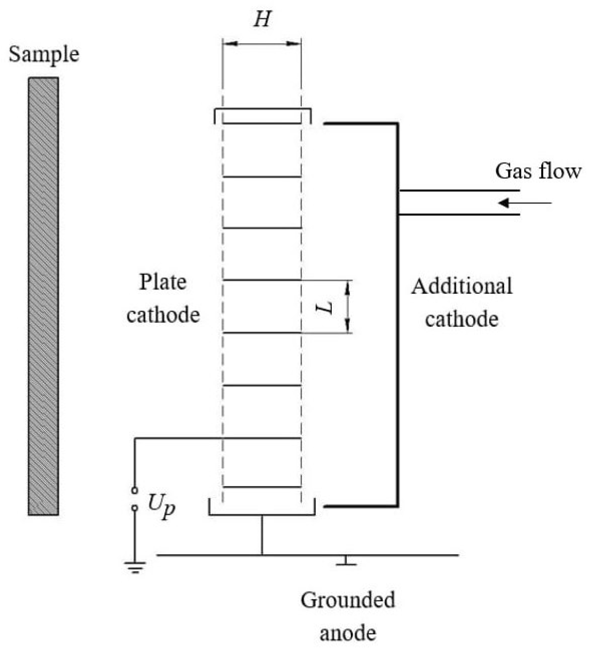
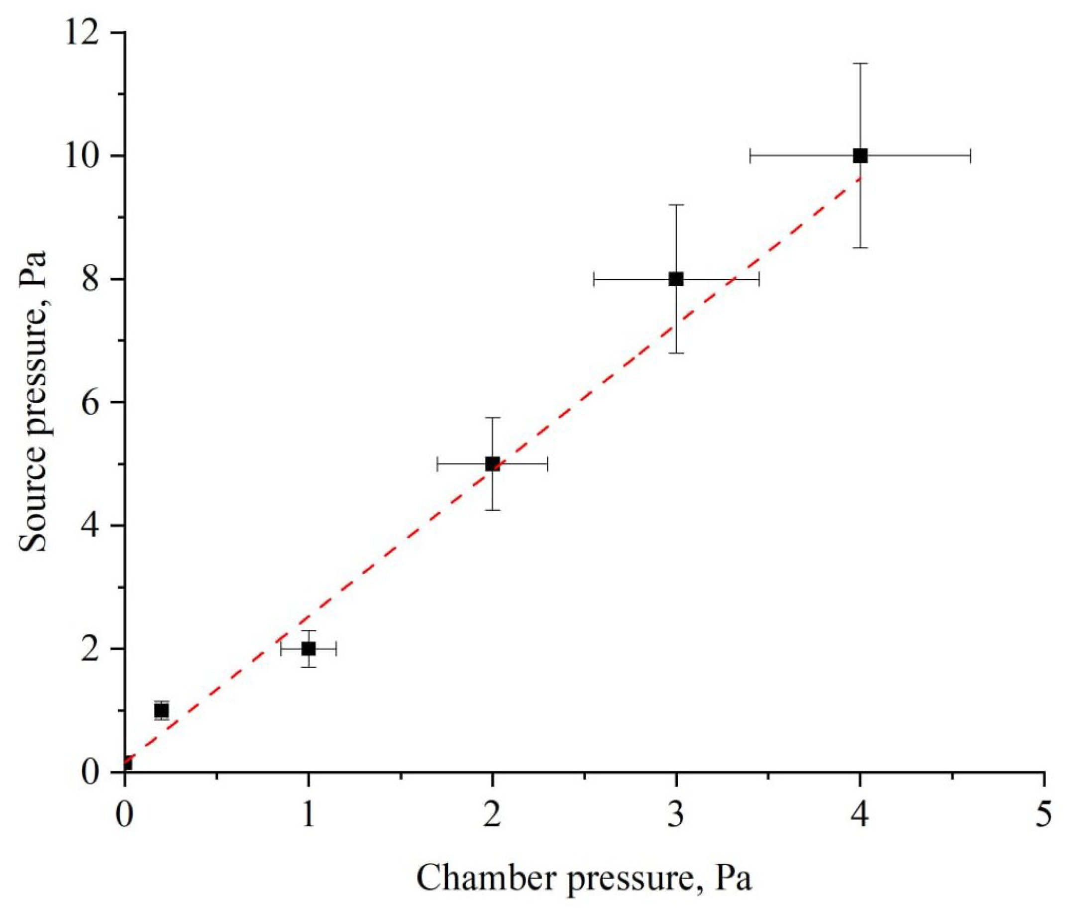
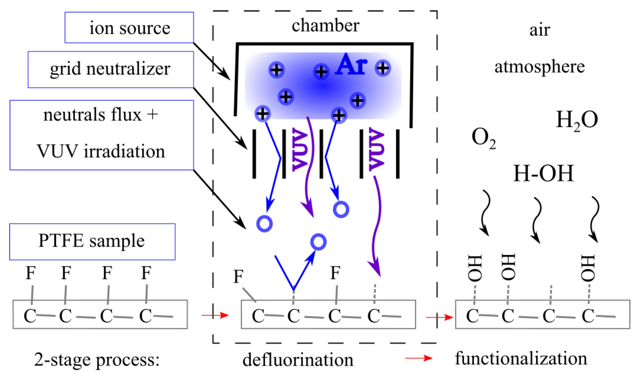
2.2. Fast-Neutrals Activation

The activation of the PTFE sample surface was conducted on an experimental vacuum setup fitted with a high-vacuum pumping system, an automated system for maintaining a specified pressure in the working chamber, and a source of fast neutrals. The residual pressure in the chamber did not exceed 0.5 Pa.
A source of fast neutrals using in this work based on a low-pressure glow discharge utilizes a triode electrode system (see Figure 1) with hollow cathode and neutralizator. The overall dimensions of the source are of 150 mm × 350 mm. This source comprises three electrodes: a neutralizing cathode constructed as a series plates (the length of the cathode plates H = 15 mm and the distance between them L = 10 mm); an anode that encircles the cathode and is grounded; an additional hollow cathode designed as a rectangular cavity open on one side towards the neutralizing cathode.
The main and additional cathodes together create a quasi-closed volume where electron oscillations occur, facilitating the hollow cathode effect and establishing conditions for electrostatic plasma confinement. The gas discharge plasma is concentrated in the space defined by the cathodes, resulting in higher particle density in the output beam. Furthermore, the hollow cathode effect reduces the minimum pressure required for sustaining stable discharge in the plasma-forming gas introduced into the source volume. A negative voltage is applied to both the main and additional cathodes.
A notable aspect of the described system is that the plate cathode impedes the flow of gas through it, particularly at low pressures when the gas flow exhibits molecular behavior. Under conditions where gas is injected into the source and continuously pumped, this creates a pressure gradient, significantly lowering the pressure in the process chamber while maintaining enough pressure inside the source for stable discharge operation (see Figure 2). The pressure was measured using Edwards WRG-S (Edwards Limited, Burgess Hill, UK) with an accuracy of 15%.
The fast neutrals source is powered by an APEL-IS-5000A (Prikladnaya Electronica, Tomsk, Russia) unit with the following characteristics (output power 2 kW, output voltage range 0.2–5.0 kV, maximum current 1 A).
Before conducting the activation experiments, the emission spectra were analyzed for all the working gases used.
The PTFE samples were positioned in the discharge chamber at a distance of 60 mm from the fast-neutral source. The treatment duration was measured starting from the moment the discharge was initiated.
After the plasma treatment was completed, the samples underwent further examination (WCA measurements) immediately upon removal from the chamber, without any additional treatment. To obtain each experimental data point, 10 samples were treated under identical process conditions and analyzed.

2.3. Activation by the Techniques Used in Industrial Environments

Experiments were performed on PTFE activation techniques typically utilized in industrial environments to assess their effectiveness compared to the proposed method. These experiments involved activation by corona discharge [10] and chemical treatment [5,6].

2.3.1. Activation by Corona Discharge

The surface of the PTFE samples was activated using a setup designed for processing PTFE tape up to 200 mm wide. Samples measuring 1 mm in thickness and 100 × 250 mm2 in size were treated at atmospheric pressure in corona discharge plasma with a two-electrode system. The upper corona electrode consists of a series of evenly spaced metal needles positioned 5 mm apart. The distance between the sample and the upper electrode was 20 mm, the applied voltage was 30 kV, and the processing time was 30 s, with the sample moving beneath the corona electrode at a speed of 0.6 m/min.

2.3.2. Chemical Activation

The liquid chemical activation of the PTFE surface was conducted using a sodium-naphthalene complex solution. This complex contains metallic sodium and naphthalene dissolved in tetrahydrofuran, mixed in the following weight proportions: tetrahydrofuran—88.5 wt%, naphthalene—12.8 wt%, metallic sodium—4.6 wt%. The processing of fluoroplastic samples involved several steps. First, the plates were degreased by immersion in gasoline-solvent, followed by drying at 35 °C for 15 min. Then, the parts were submerged in a container with the sodium-naphthalene complex for 30 s at 25 ± 5 °C. Subsequently, the treated parts were rinsed by immersion in acetone for 1 min at 25 ± 15 °C, followed by rinsing under running water for 20 min. Finally, they were dried at room temperature for 10 h.

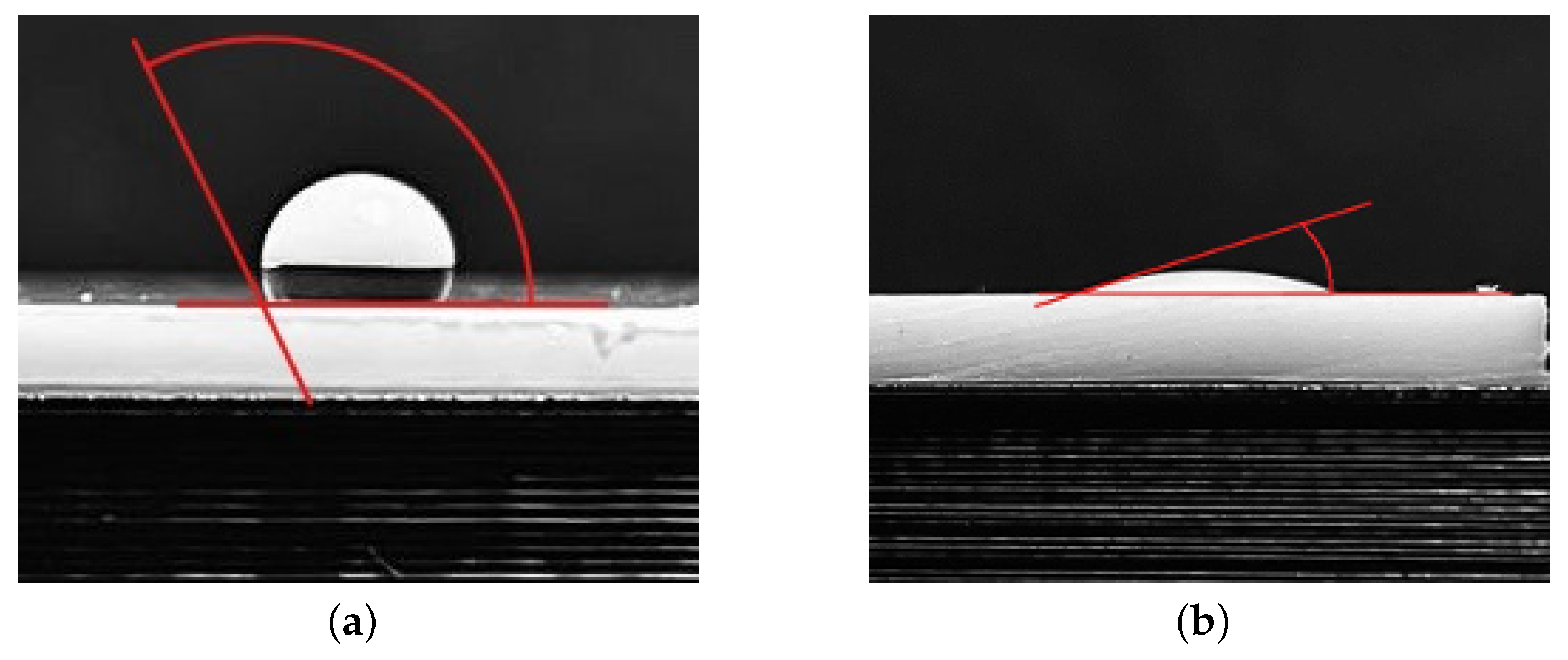
2.4. Water Contact Angle Measurement

To assess the hydrophilicity of the PTFE surface, water contact angle (WCA) measurements were taken at the interface between distilled water and the polymer. Using a dispenser drops of 1 mL were placed on the surface at varying time intervals after the activation (from 0 min to 24 h). An example of the contact angle before (WCA0) and after the activation ( WCA f ) is shown in Figure 3. For untreated PTFE, the WCA0 value typically falls within the range of 110° to 130° according to literature data, and was measured as 116° in this study.
To calculate the surface energy, WCA measurements were taken using ethyl alcohol and glycerol following the same measurement protocol.

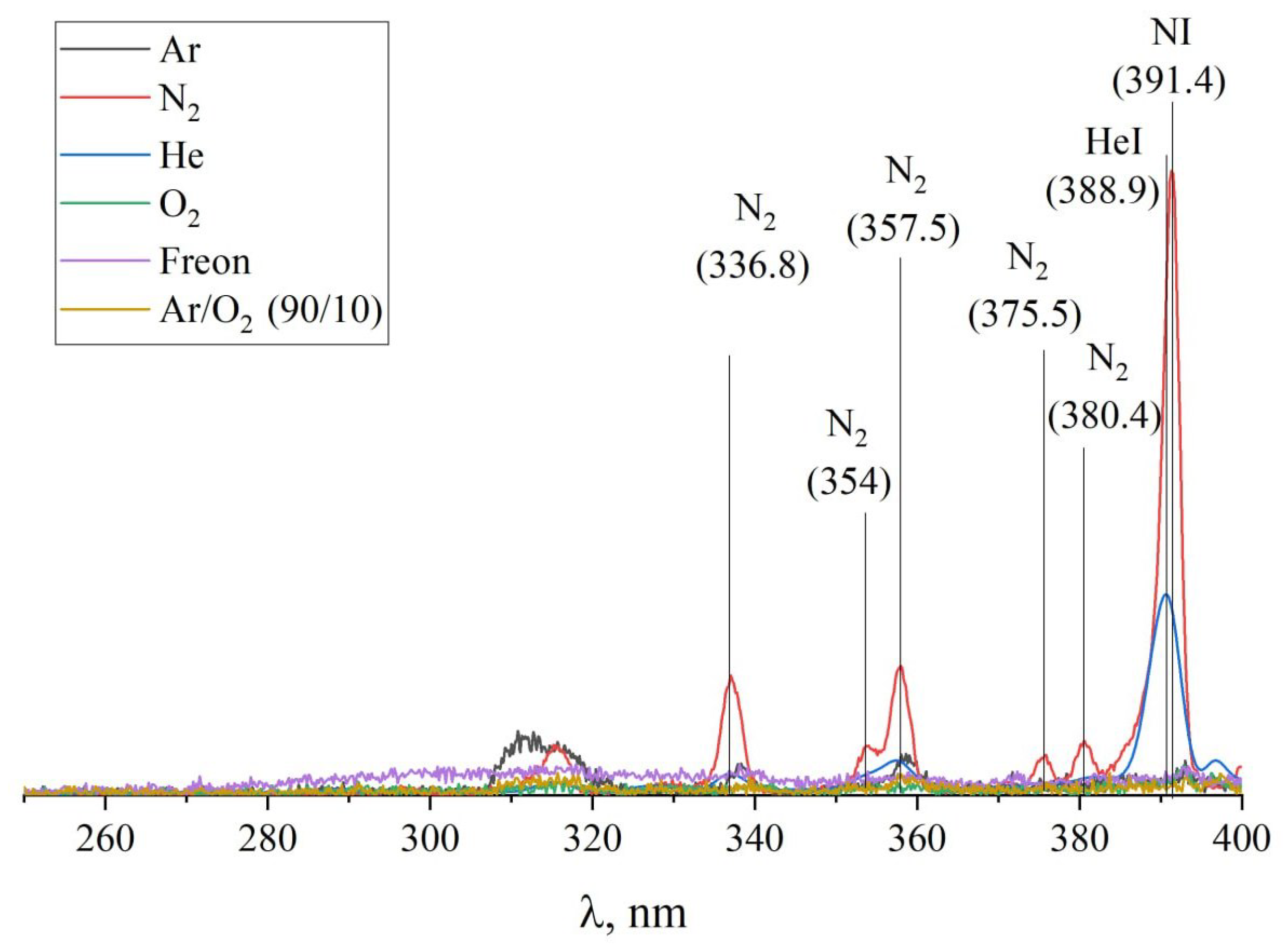
2.5. Plasma Optical Spectra Measurements

To measure optical spectra, the study employs the ISM3600 spectrometer (ETU "LETI", St. Petersburg, Russia) [51,52], which features a spectral line database enabling the determination of the elemental and ionic composition of the gas discharge. The spectrometer is capable of recording optical radiation spectra within the range of 250–1000 nm, with a spectral resolution of no more than 2.5 ± 0.5 nm in the visible spectrum. The optical signal produced by the plasma is conveyed from the vacuum chamber using a quartz fiber optic cable with a diameter of 0.4 mm.

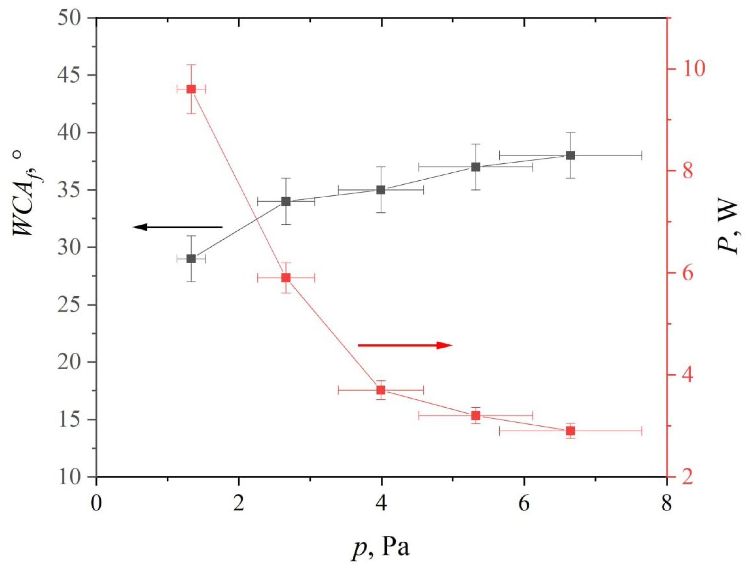
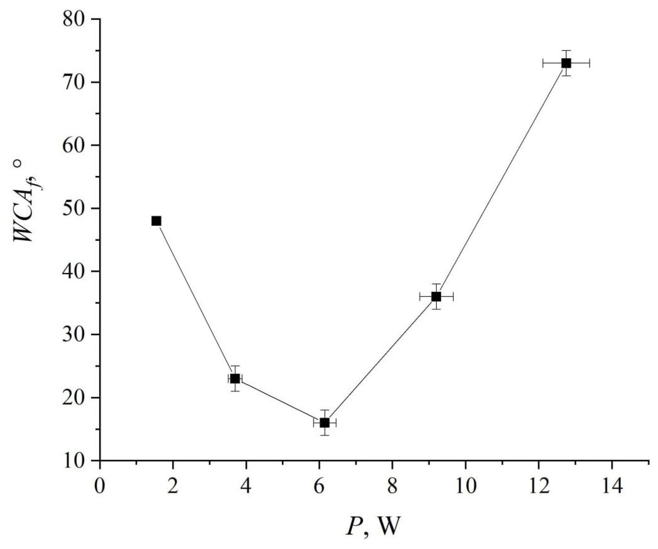
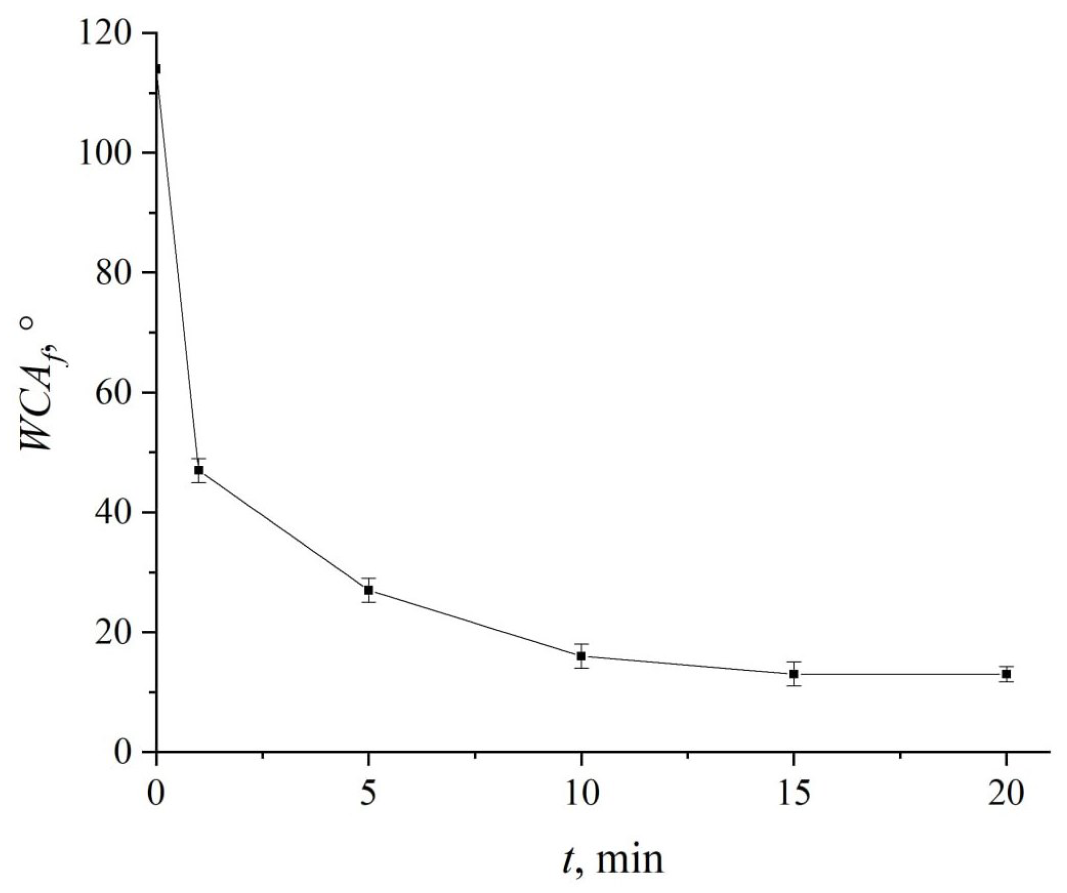
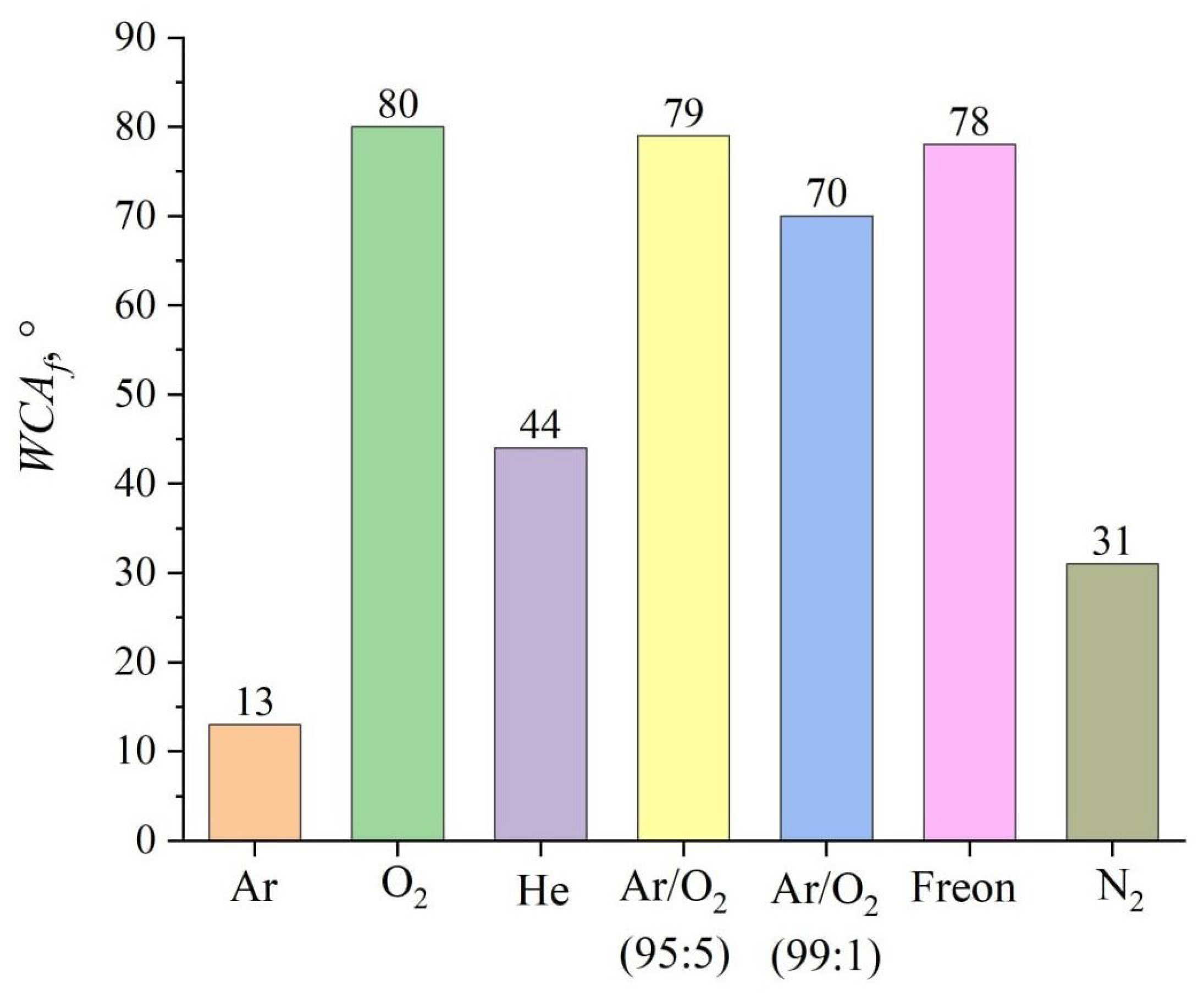
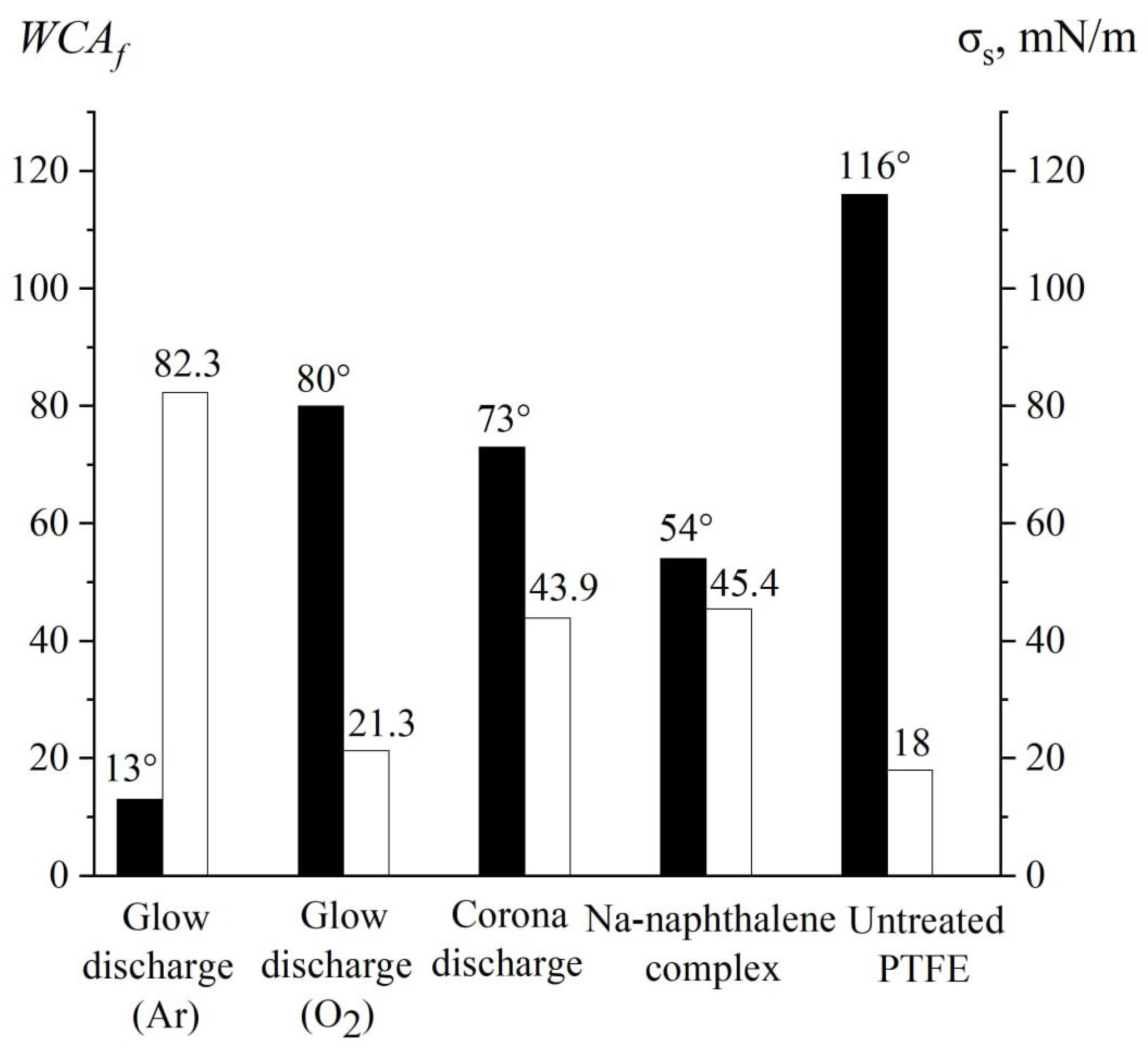
3. Results and Discussion

To determine the optimal conditions for activating the PTFE surface, a series of experiments involving sample processing in glow discharge plasma was conducted. Initially, argon was selected as the working gas due to numerous literature references. The study was performed under a stabilized discharge current of 10 mA. The lower limit of the pressure range was set at 1.33 Pa, which ensured stable maintenance of the discharge.
The influence of the working gas pressure is depicted in Figure 4, where the pressure was measured in the main working chamber near the sample’s position. Argon served as the working gas, while the discharge current was consistently held at 10 mA throughout the experiment. As seen from the graph, increasing the pressure leads to an increase in the WCA. This phenomenon can be explained by Paschen’s law, which states that higher pressures cause a drop in voltage and discharge power. Additionally, the mean free path of fast neutrals decreases. These combined effects result in a diminished impact on the sample surface.
Figure 5 depicts the relationship between the contact angle and the discharge power. The experiments were performed at a pressure of 1.33 Pa, a discharge current of 15 mA, and using argon as the working gas. The dependence reveals a pronounced minimum: as the power rises, the wetting angle decreases to 16°, reached at a discharge voltage of 410 V and a current of 15 mA. The observed relationship aligns with findings reported in the literature [13,17,20] and can be explained by the etching, when the power exceeds a certain threshold [16,17].
The study of the effect of surface treatment duration was conducted at an argon pressure of 1.33 Pa, using an optimal discharge power with a voltage of 410 V and a discharge current of 15 mA (refer to Figure 5). The results presented in Figure 6 indicate that the maximum effect is achieved within 10 min of treatment, during which the contact angle decreases from 114° to 16°. Prolonged treatment further reduces the angle down to 13° at a duration of 20 min.
A study of the dynamics of the contact angle recovery reveals that the degradation of hydrophilic properties commences after one hour, with the contact angle nearly doubling from 13° to 29° within the initial 48 hours. However, it takes six days for the contact angle values to approach those observed following treatment in a corona discharge (see Figure 7).
A series of experiments were conducted using various gases such as N2, O2, He, CF4 (Freon 134A), and mixtures of Ar and O2 in different proportions, following the same measurement protocol as for the argon treatment. Figure 8 presents the measured average WCA values after each treatment. PTFE surfaces treated in an argon atmosphere exhibited the most effective hydrophilic properties, achieving a WCA of 13°. In contrast, the use of reactive gases—nitrogen, oxygen, and freon—only allows reducing the WCA to comparatively higher values of 31°, 80°, and 78°, respectively. Adding minor concentrations of oxygen (1% to 5%) to argon significantly impaired the hydrophilic characteristics. Moreover, a series of trials with helium contradicted the idea that inert gases are ideal for PTFE processing, as the WCA rose to 44°.
The spectral analyzer used in this study captures the plasma emission spectrum within the visible and near-UV range (250–1000 nm), but is incapable of detecting signals in the vacuum ultraviolet (VUV) region (<200 nm), representing a limitation of the employed equipment. According to the literature [33], the breakdown of C-F bonds in PTFE is initiated by VUV radiation. Common gases, such as helium, argon, and nitrogen, exhibit emissions in both the measurable and unobservable (VUV) regions, as reported in the literature [53]. Detection of emission in the 250–400 nm range suggests probable VUV emissions; conversely, missing expected peaks imply the absence of emission elsewhere.
Figure 9 presents the results of optical emission spectroscopy in the 250–400 nm range for gas-phase plasma without the presence of PTFE or other materials in the chamber. Line identification was performed using standardized reference databases [54], with special emphasis on molecular nitrogen [55,56,57]. Measurements were conducted at a constant working gas pressure of 1.33 Pa. The spectrometer’s resolution limit of 2 nm occasionally merges closely spaced atomic lines into broader bands [52]. This effect is particularly evident for argon atom lines at 306.5, 307.8, 309.3, 311.0, 312.8, and 315.1 nm, as shown in Figure 10.
It is important to highlight that adding small amounts of oxygen to argon leads to a sharp decrease in the intensity of ultraviolet radiation emitted by the plasma. This effect arises because the ionization process switches from argon to oxygen, driven by the lower ionization energy of oxygen (13.6 eV for atomic and 12.2 eV for molecular forms) compared to argon (15.8 eV). Figure 10 clearly contrasts the emission spectra of pure argon and argon-oxygen mixtures, clearly depicting the pronounced shift in ionization dynamics. Throughout the spectrum, the intensity of argon emissions significantly diminishes, while the spectrum of atomic oxygen emerges at 777.5 nm. Due to the resolution limitations of our instrument, we are unable to resolve the closely packed triplet of oxygen lines at 777.2, 777.4, and 777.5 nm.
To theoretically describe the adhesive properties of the material’s surface under study, it is recommended to evaluate the surface tensions of the phases at the interface are related to the cosine of the WCA via Young’s equation [58]:
σ S = σ S L + σ L cos θ ,
where σ S is the equilibrium surface tension of the solid, σ S L is the interfacial surface tension at the solid-liquid boundary, and σ L is the equilibrium surface tension of the liquid. To precisely determine the magnitude of surface energy, it is crucial to consider the nature of the forces acting at the phase contact. Adhesive and cohesive forces stem from intermolecular interactions, commonly classified into van der Waals and polar interactions, resulting in the division of surface energy into respective components. This approach is utilized in the Owens-Wendt-Rabel-Kaelble (OWRK) [59] interfacial interaction model (see Appendix A).
The summarized results for the water contact angle ( WCA f ) and surface energy σ S for various activation techniques are presented in Figure 11.
Activation of PTFE surfaces by plasma treatment, as established in prior works [21,40,41], involves two distinct processes. Firstly, defluorination occurs, during which high-energy neutral particles and UV radiation from the glow discharge plasma cleave fluorine bonds. Following defluorination, functionalization takes place, during which polar groups critical for enhancing wettability are formed on the PTFE surface. In most earlier works, this functionalization stage is facilitated by reactive gases such as nitrogen or oxygen, added to the glow discharge plasma, allowing both defluorination and functionalization to occur simultaneously.
In the proposed method (see Figure 12), pure argon is used as the working gas, enabling defluorination to occur solely within the chamber. Using argon allows effective utilization of VUV irradiation, while the low power of the DC discharge minimizes surface etching. Functionalization then proceeds spontaneously once the sample is exposed to atmospheric conditions. Although these processes are not simultaneous, this sequential two-stage approach has proven effective, leading to significant improvements in surface wettability. The results correspond to earlier findings [21], confirming the validity of the proposed method.

4. Conclusions

The study demonstrates the feasibility of a novel method for PTFE surface activation using a fast neutral flow generated by a DC glow discharge plasma with pure argon as the working gas. Plasma radiation, particularly in the VUV range, plays a critical role in improving surface wettability. Introduction of oxygen into the argon mixture adversely impacts the efficiency of the process by diverting ionization to oxygen atoms, thus reducing the intensity of UV radiation. However, pure argon plasma exhibits superior performance compared to nitrogen and helium, suggesting that factors beyond VUV radiation contribute to the activation process.
The method implements a two-stage activation process: defluorination inside the chamber and subsequent functionalization in ambient air. Functionalization is facilitated by polar groups formed naturally on the PTFE surface due to interaction with atmospheric oxygen and nitrogen. The process achieves a significant reduction in the contact angle (from 116° to 13°) and an increase in the polar component of surface energy (up to 78 mN/m).
Key advantages of the proposed method include the absence of fast ions, preventing charging effects, and stable operation at low power levels, minimizing physical sputtering and surface damage. These attributes render the method suitable for industrial-scale applications, providing a cost-effective and efficient solution for PTFE surface modification.

Author Contributions

Conceptualization, A.K. and D.K.; methodology, A.K. and D.K.; validation, A.K., A.A. and A.G.; software A.T.; formal analysis, D.K.; investigation, D.K., I.N., Y.S. and A.T.; resources, A.K.; data curation, A.G.; writing—original draft preparation, D.K., A.G. and A.K.; writing—review and editing, A.G. and D.K.; visualization, D.K.; supervision, R.P.; project administration, R.P.; funding acquisition, A.K., A.A. and A.G. All authors have read and agreed to the published version of the manuscript.

Funding

This research was funded by The Ministry of Education and Science of the Russian Federation within the framework of the state assignment No. 075-01438-22-07 (FSEE-2025-0009).

Institutional Review Board Statement

Not applicable.

Informed Consent Statement

Not applicable.

Data Availability Statement

The original contributions presented in this study are included in the article. Further inquiries can be directed to the corresponding author.

Conflicts of Interest

The authors declare no conflicts of interest.

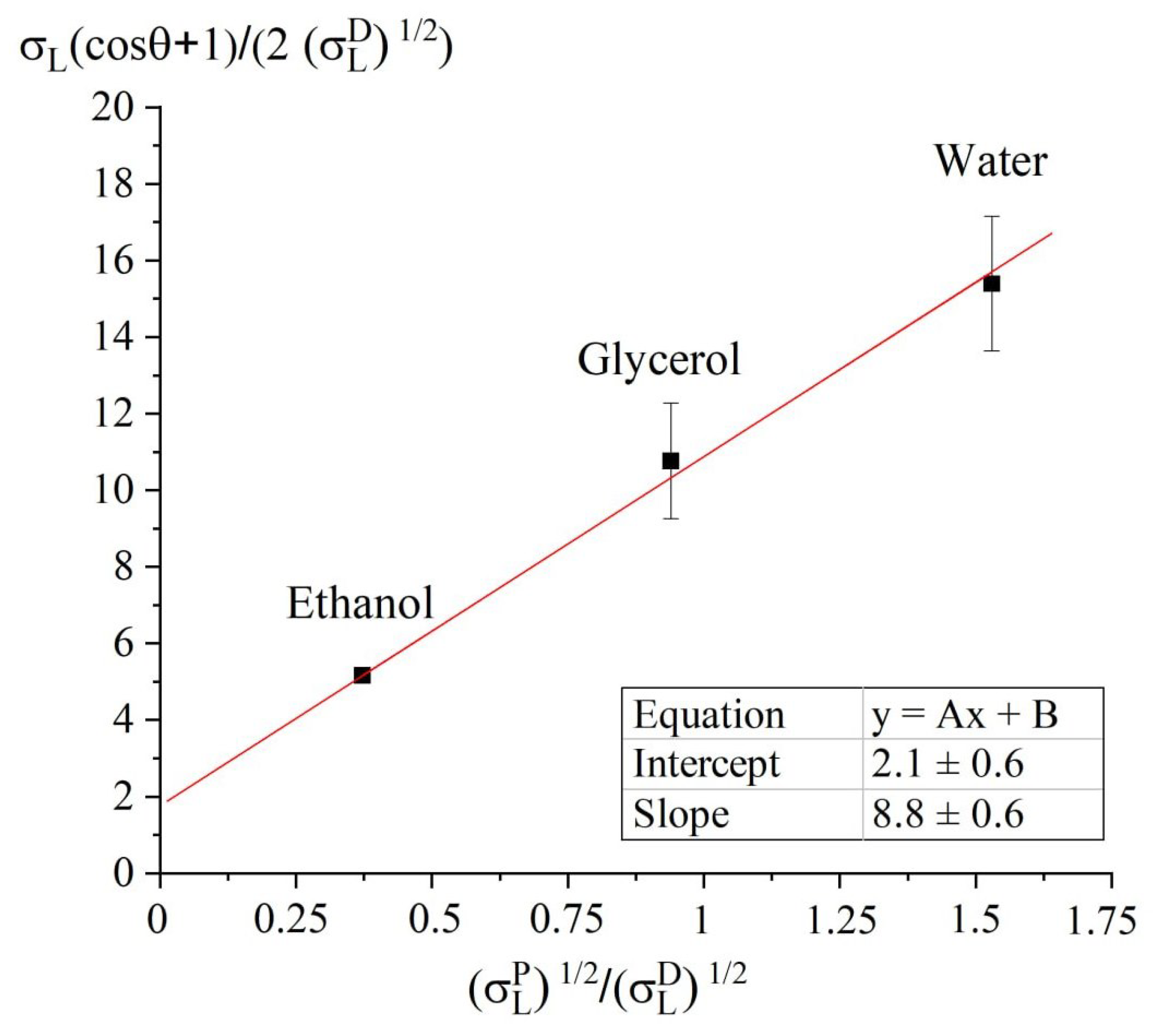
Appendix A. Estimation of the Surface Energy by Owens-Wendt-Rabel- Kaelble Model

Owens-Wendt-Rabel-Kaelble (OWRK) interfacial interaction model facilitates the estimation of the surface energy components of solids based on experimentally measured WCAs ( θ ) with test liquids [59]:
σ L cos θ + 1 2 σ L D = σ L P σ L D σ S P + σ S D ,
σ S = σ S D + σ S P ,
σ L = σ L D + σ L P ,
where σ L D , σ L P are the dispersion and polar components of the surface energy of a liquid, and σ S D , σ S P are the dispersion and polar components of the surface energy of a solid.
The WCA of the samples was measured using working liquids with known polar and dispersion components of surface tension: water, ethyl alcohol, and glycerol (see Table A1). Measurements with different working liquids were conducted simultaneously on samples activated within a single process. The results of these measurements are summarized in Table A2.
The surface energy value σ S of the activated polytetrafluoroethylene sample, along with its polar σ S P and dispersion components σ S D , was determined by constructing an approximation dependence corresponding to Equation (A1). Figure A1 illustrates how to calculate these parameters. By applying a linear approximation to the relationship depicted in the figure, we can determine the approximation parameters A and B. These parameters are then used to compute the corresponding surface energy values as follows:
σ S P = A 2 , σ S D = B 2 .
Table A1. Values of surface energy and its polar and dispersion components of the liquids used [60].
Liquid σ L P , mN/m σ L P , mN/m σ L , mN/m
Water5121.872.8
Glycerol303464
Ethanol2.618.822.4
Table A2. Values of the WCAs of activated PTFE measured with various liquids.
TreatmentWCA θ , °
WaterGlycerolEthanol
untreated PTFE
1161459
Glow discharge
Ar13160
O280996
He44543
99%/1% O279976
95%/5% O270865
Freon78966
N231382
Corona discharge
Air73902
Chemical treatment
Na-naphtalene complex54674
Figure A1. Determination of surface energy of PTFE plate treated in argon glow discharge.
Coatings 15 00644 g0a1
Table A3 presents the results of determining the surface tension components of PTFE sheets activated by various methods. The standard surface energy value for pure (non-activated) PTFE is 18 mN/m, with the polar component assumed to be absent. Depending on the treatment type, the values of the surface energy components vary widely, but the polar component value is generally decisive and enables characterization of the treatment method’s efficiency. Notably, the highest surface energy value was achieved after treating the PTFE surface in an argon discharge (82.3 mN/m), with an exceptionally high polar component. This suggests the formation of polar groups (such as hydroxyl or carboxyl) on the surface.
It is worth noting that the use of test markers or inks, commonly employed in the polymer industry to measure surface energy, only permits an evaluation within the range of 30–60 mN/m (Accu Dyne Test). This limited scope is inadequate for investigating the impact of glow discharge on the properties of the PTFE surface.
Table A3. Surface energies of the activated PTFE.
Treatment σ S P , mN/m σ S D , mN/m σ S , mN/m
untreated PTFE
0.0 ± 0.0 18 ± 1 18 ± 1
Glow discharge
Ar 78 ± 11 4.3 ± 2.5 82 ± 13
O2 12 ± 2 8.9 ± 3.6 21 ± 6
He 65 ± 8 1.3 ± 1.1 66 ± 9
99%/1% O2 44 ± 5 0.0 ± 0.0 44 ± 5
95%/5% O2 37 ± 6 0.1 ± 0.1 37 ± 6
Freon 38 ± 3 3.3 ± 1.5 41 ± 4
N2 73 ± 2 2.5 ± 0.3 75 ± 2
Corona discharge
Air 28 ± 3 16 ± 3 44 ± 6
Chemical treatment
Na-naphtalene complex 39 ± 8 6.0 ± 2.5 45 ± 10

References

  1. Dhanumalayan, E.; Joshi, G.M. Performance properties and applications of polytetrafluoroethylene (PTFE)—A review. Adv. Compos. Hybrid Mater. 2018, 1, 247–268. [Google Scholar] [CrossRef]
  2. Ebnesajjad, S. Expanded PTFE Applications Handbook: Technology, Manufacturing and Applications; William Andrew: Norwich, NY, USA, 2016. [Google Scholar]
  3. Domalanta, M.R.B.; Caldona, E.B. Toward Enhancing the Surface Adhesion of Fluoropolymer-Based Coating Materials. Polym. Rev. 2024, 64, 980–1030. [Google Scholar] [CrossRef]
  4. Schonhorn, H.; Ryan, F.W. Adhesion of polytetrafluoroethylene. J. Adhes. 1969, 1, 43–47. [Google Scholar] [CrossRef]
  5. Lee, K.W.; Viehbeck, A. Wet-process surface modification of dielectric polymers: Adhesion enhancement and metallization. IBM J. Res. Dev. 1994, 38, 457–474. [Google Scholar] [CrossRef]
  6. Rojas, G. Recent Advances in Fluoropolymers: Copolymers of Tetrafluoroethylene and Related Fluorinated Molecules. Available online: http://www.researchgate.net/publication/242686971_Recent_Advances_in_Fluoropolymers_Copolymers_of_Tetrafluoroethylene_and_Related_Fluorinated_Molecules (accessed on 22 May 2025).
  7. Roina, Y.; Gonçalves, A.M.; Fregnaux, M.; Auber, F.; Herlem, G. Sodium naphthalenide diglyme solution for etching ptfe, characterizations and molecular modelization. ChemistrySelect 2022, 7, e202200153. [Google Scholar] [CrossRef]
  8. Gabriel, M.; Dahm, M.; Vahl, C.F. Wet-chemical approach for the cell-adhesive modification of polytetrafluoroethylene. Biomed. Mater. 2011, 6, 035007. [Google Scholar] [CrossRef]
  9. Lee, J.H.; Kim, H.G.; Khang, G.S.; Lee, H.B.; Jhon, M.S. Characterization of wettability gradient surfaces prepared by corona discharge treatment. J. Colloid Interface Sci. 1992, 151, 563–570. [Google Scholar] [CrossRef]
  10. Markgraf, D.A. Corona treatment: An overview. In Polymers Laminations and Coatings Conference; TAPPI Press: Atlanta, GA, USA, 1994; p. 159. [Google Scholar]
  11. Olariu, M.A.; Herrero, R.; Astanei, D.G.; Jofré, L.; Morentin, J.; Filip, T.A.; Burlica, R. Improving Printability of Polytetrafluoroethylene (PTFE) with the Help of Plasma Pre-Treatment. Polymers 2023, 15, 3348. [Google Scholar] [CrossRef]
  12. Jie-Rong, C.; Wakida, T. Studies on the surface free energy and surface structure of PTFE film treated with low temperature plasma. J. Appl. Polym. Sci. 1997, 63, 1733–1739. [Google Scholar] [CrossRef]
  13. Liu, C.; Arnell, R.; Gibbons, A.; Green, S.; Ren, L.; Tong, J. Surface modification of PTFE by plasma treatment. Surf. Eng. 2000, 16, 215–217. [Google Scholar] [CrossRef]
  14. Liu, C.; Wu, J.; Ren, L.; Tong, J.; Li, J.; Cui, N.; Brown, N.; Meenan, B. Comparative study on the effect of RF and DBD plasma treatment on PTFE surface modification. Mater. Chem. Phys. 2004, 85, 340–346. [Google Scholar] [CrossRef]
  15. Wilson, D.; Williams, R.; Pond, R. Plasma modification of PTFE surfaces. Part I: Surfaces immediately following plasma treatment. Surf. Interface Anal. 2001, 31, 385–396. [Google Scholar] [CrossRef]
  16. Bruce, R.; Weilnboeck, F.; Lin, T.; Phaneuf, R.; Oehrlein, G.; Long, B.; Willson, C.; Vegh, J.; Nest, D.; Graves, D. Relationship between nanoscale roughness and ion-damaged layer in argon plasma exposed polystyrene films. J. Appl. Phys. 2010, 107, 084310. [Google Scholar] [CrossRef]
  17. Zanini, S.; Bami, R.; Della Pergola, R.; Riccardi, C. Development of super-hydrophobic PTFE and PET surfaces by means of plasma processes. J. Phys. 2014, 550, 012029. [Google Scholar] [CrossRef]
  18. Hai, W.; Hi, T.; Shimizu, K.; Yajima, T. Preparation of a super hydrophilic polytetrafluoroethylene surface using a gaseous ammonia-water low-temperature plasma. J. Photopolym. Sci. Technol. 2015, 28, 479–483. [Google Scholar] [CrossRef]
  19. Nguyen, H.D.; Yajima, T. A spectroscopic study on argon-ammonia water gaseous plasma super-hydrophilizing polytetrafluoroethylene. J. Photopolym. Sci. Technol. 2017, 30, 325–330. [Google Scholar] [CrossRef]
  20. Vesel, A.; Zaplotnik, R.; Primc, G.; Mozetič, M.; Katan, T.; Kargl, R.; Mohan, T.; Kleinschek, K.S. Rapid functionalization of polytetrafluorethylene (PTFE) surfaces with nitrogen functional groups. Polymers 2021, 13, 4301. [Google Scholar] [CrossRef]
  21. Lojen, D.; Primc, G.; Mozetič, M.; Vesel, A. Optimization of surface wettability of polytetrafluoroethylene (PTFE) by precise dosing of oxygen atoms. Appl. Surf. Sci. 2022, 598, 153817. [Google Scholar] [CrossRef]
  22. Zhang, Y.; Ishikawa, K.; Mozetič, M.; Tsutsumi, T.; Kondo, H.; Sekine, M.; Hori, M. Polyethylene terephthalate (PET) surface modification by VUV and neutral active species in remote oxygen or hydrogen plasmas. Plasma Process. Polym. 2019, 16, 1800175. [Google Scholar] [CrossRef]
  23. Károly, Z.; Kalácska, G.; Zsidai, L.; Mohai, M.; Klébert, S. Improvement of adhesion properties of polyamide 6 and polyoxymethylene-copolymer by atmospheric cold plasma treatment. Polymers 2018, 10, 1380. [Google Scholar] [CrossRef]
  24. Hunke, H.; Soin, N.; Shah, T.H.; Kramer, E.; Pascual, A.; Karuna, M.S.L.; Siores, E. Low-Pressure H2, NH3 microwave plasma treatment of polytetrafluoroethylene (PTFE) powders: Chemical, thermal and wettability analysis. Materials 2015, 8, 2258–2275. [Google Scholar] [CrossRef]
  25. Károly, Z.; Kalácska, G.; Sukumaran, J.; Fauconnier, D.; Kalácska, Á.; Mohai, M.; Klébert, S. Effect of atmospheric cold plasma treatment on the adhesion and tribological properties of polyamide 66 and poly (tetrafluoroethylene). Materials 2019, 12, 658. [Google Scholar] [CrossRef] [PubMed]
  26. Hong, S.H.; Kim, T.H.; Choi, S. Hydrophilic surface modification of polytetrafluoroethylene film with gliding arc plasma. Appl. Sci. Converg. Technol. 2019, 28, 101–106. [Google Scholar] [CrossRef]
  27. Kolská, Z.; Řezníčková, A.; Hnatowicz, V.; Švorčík, V. PTFE surface modification by Ar plasma and its characterization. Vacuum 2012, 86, 643–647. [Google Scholar] [CrossRef]
  28. Rychkov, D.; Yablokov, M.; Rychkov, A. Chemical and physical surface modification of PTFE films—An approach to produce stable electrets. Appl. Phys. A 2012, 107, 589–596. [Google Scholar] [CrossRef]
  29. Carbone, E.; Verhoeven, M.; Keuning, W.; Van Der Mullen, J. PTFE treatment by remote atmospheric Ar/O2 plasmas: A simple reaction scheme model proposal. J. Phys. 2016, 715, 012011. [Google Scholar]
  30. Yablokov, M.Y.; Kuznetsov, A.A. Electret properties and wettability of polymer materials treated by DC glow discharge. Phys. Complex Syst. 2024, 5, 202–204. [Google Scholar] [CrossRef]
  31. Heo, W.; Han, D.H.; Oh, S.J.; Yoon, J.U.; Woo, I.; Choi, S.E.; Yoon, J.M.; Bae, J.W. Enhancing polymer electrolyte membrane fuel cell performance and efficiency: Plasma-treated effects of expanded polytetrafluoroethylene in reinforced composite membranes. J. Power Sources 2025, 642, 237010. [Google Scholar] [CrossRef]
  32. Takahashi, T.; Hirano, Y.; Takasawa, Y.; Gowa, T.; Fukutake, N.; Oshima, A.; Tagawa, S.; Washio, M. Change in surface morphology of polytetrafluoroethylene by reactive ion etching. Radiat. Phys. Chem. 2011, 80, 253–256. [Google Scholar] [CrossRef]
  33. Esrom, H.; Zhang, J.Y.; Kogelschatz, U. Photochemical modification and etching of PTFE with excimer VUV/UV radiation. In Polymer Surfaces and Interfaces: Characterization, Modification and Application; CRC Press: Boca Raton, FL, USA, 2023; pp. 27–35. [Google Scholar]
  34. Egitto, F.; Matienzo, L. Modification of polytetrafluoroethylene and polyethylene surfaces downstream from helium microwave plasmas. Polym. Degrad. Stab. 1990, 30, 293–308. [Google Scholar] [CrossRef]
  35. Takacs, G.; Vukanovic, V.; Tracy, D.; Chen, J.; Egitto, F.; Matienzo, L.; Emmi, F. Photoetching and modification of organic polymer surfaces with vacuum UV Radiation. Polym. Degrad. Stab. 1993, 40, 73–81. [Google Scholar] [CrossRef]
  36. López, C.D.; Cedeño-Mata, M.; Dominguez-Pumar, M.; Bermejo, S. Surface modification of polytetrafluoroethylene thin films by non-coherent UV light and water treatment for electrowetting applications. Prog. Org. Coat. 2020, 149, 105593. [Google Scholar] [CrossRef]
  37. Heitz, J.; Niino, H.; Yabe, A. Chemical surface modification on polytetrafluoroethylene films by vacuum ultraviolet excimer lamp irradiation in ammonia gas atmosphere. Appl. Phys. Lett. 1996, 68, 2648–2650. [Google Scholar] [CrossRef]
  38. Takacs, G.A.; Miri, M.J.; Kovach, T. Vacuum UV surface photo-oxidation of polymeric and other materials for improving adhesion: A critical review. Prog. Adhes. Adhes. 2021, 6, 559–585. [Google Scholar]
  39. Takacs, G.A.; Miri, M.J. Vacuum UV (VUV) Photo-Oxidation of Polymer Surfaces to Enhance Adhesion. In Polymer Surface Modification to Enhance Adhesion: Techniques and Applications; John Wiley & Sons: Hoboken, NJ, USA, 2024; pp. 119–154. [Google Scholar]
  40. Primc, G. Recent advances in surface activation of polytetrafluoroethylene (PTFE) by gaseous plasma treatments. Polymers 2020, 12, 2295. [Google Scholar] [CrossRef]
  41. Matienzo, L.; Zimmerman, J.; Egitto, F. Surface modification of fluoropolymers with vacuum ultraviolet irradiation. J. Vac. Sci. Technol. A Vac. Surfaces Film. 1994, 12, 2662–2671. [Google Scholar] [CrossRef]
  42. Lojen, D.; Primc, G.; Mozetič, M.; Vesel, A. Effect of VUV radiation and reactive hydrogen atoms on depletion of fluorine from polytetrafluoroethylene surface. Appl. Surf. Sci. 2020, 533, 147356. [Google Scholar] [CrossRef]
  43. Dasilva, W.; Entenberg, A.; Kahn, B.; Debies, T.; Takacs, G. Surface modification of Teflon® PFA with vacuum UV photo-oxidation. J. Adhes. Sci. Technol. 2006, 20, 437–455. [Google Scholar] [CrossRef]
  44. Shimokawa, F.; Tanaka, H.; Uenishi, Y.; Sawada, R. Reactive–fast-atom beam etching of GaAs using Cl2 gas. J. Appl. Phys. 1989, 66, 2613–2618. [Google Scholar] [CrossRef]
  45. Maishev, Y.P.; Shevchuk, S.; Kudrya, V. Generation of fast neutral beams based on closed drift ion sources. Russ. Microelectron. 2014, 43, 345–351. [Google Scholar] [CrossRef]
  46. Mizutani, T.; Nishimatsu, S. Sputtering yield and radiation damage by neutral beam bombardment. J. Vac. Sci. Technol. A Vac. Surfaces Film. 1988, 6, 1417–1420. [Google Scholar] [CrossRef]
  47. Panda, S.; Economou, D.J.; Chen, L. Anisotropic etching of polymer films by high energy (100 s of eV) oxygen atom neutral beams. J. Vac. Sci. Technol. A Vac. Surfaces Film. 2001, 19, 398–404. [Google Scholar] [CrossRef]
  48. Samukawa, S.; Sakamoto, K.; Ichiki, K. Generating high-efficiency neutral beams by using negative ions in an inductively coupled plasma source. J. Vac. Sci. Technol. A Vac. Surfaces Film. 2002, 20, 1566–1573. [Google Scholar] [CrossRef]
  49. Ranjan, A.; Donnelly, V.M.; Economou, D.J. Energy distribution and flux of fast neutrals and residual ions extracted from a neutral beam source. J. Vac. Sci. Technol. A 2006, 24, 1839–1846. [Google Scholar] [CrossRef]
  50. Economou, D.J. Modeling and simulation of fast neutral beam sources for materials processing. Plasma Process. Polym. 2009, 6, 308–319. [Google Scholar] [CrossRef]
  51. Kostrin, D.; Oukhov, A. Hardware-Software Spectrometric Complex for Research of the Parameters of Light-Emitting Diodes. Biotekhnosphera 2013, 21–25. (In Russian) [Google Scholar]
  52. Uhov, A.; Gerasimov, V.; Kostrin, D.; Selivanov, L. Use of compact spectrometer for plasma emission qualitative analysis. J. Phys. 2014, 567, 012039. [Google Scholar] [CrossRef]
  53. Golda, J.; Biskup, B.; Layes, V.; Winzer, T.; Benedikt, J. Vacuum ultraviolet spectroscopy of cold atmospheric pressure plasma jets. Plasma Process. Polym. 2020, 17, 1900216. [Google Scholar] [CrossRef]
  54. Kramida, A.; Ralchenko, Y.; Reader, J.; Team, N.A. NIST Atomic Spectra Database. Version 5.12. 2024. Available online: https://physics.nist.gov/asd (accessed on 18 April 2025).
  55. Qayyum, A.; Zeb, S.; Ali, S.; Waheed, A.; Zakaullah, M. Optical emission spectroscopy of abnormal glow region in nitrogen plasma. Plasma Chem. Plasma Process. 2005, 25, 551–564. [Google Scholar] [CrossRef]
  56. Suraj, K.; Bharathi, P.; Prahlad, V.; Mukherjee, S. Near cathode optical emission spectroscopy in N2–H2 glow discharge plasma. Surf. Coat. Technol. 2007, 202, 301–309. [Google Scholar] [CrossRef]
  57. Fierro, A.; Laity, G.; Neuber, A. Optical emission spectroscopy study in the VUV–VIS regimes of a developing low-temperature plasma in nitrogen gas. J. Phys. D Appl. Phys. 2012, 45, 495202. [Google Scholar] [CrossRef]
  58. Young, T. An essay on the cohesion of fluids. Philos. Trans. R. Soc. Lond. 1805, 95, 65–87. [Google Scholar]
  59. Owens, D.K.; Wendt, R. Estimation of the surface free energy of polymers. J. Appl. Polym. Sci. 1969, 13, 1741–1747. [Google Scholar] [CrossRef]
  60. Palencia, M. Surface free energy of solids by contact angle measurements. J. Sci. Technol. Appl 2017, 2, 84–93. [Google Scholar] [CrossRef]
Figure 1. Schematic diagram of the fast neutral source.
Coatings 15 00644 g001
Figure 2. Dependence of the pressure inside the source on the pressure in the process chamber.
Coatings 15 00644 g002
Figure 3. Examples of results of measuring the water contact angle (WCA): (a)—untreated PTFE WCA0 = 116°; (b)—after glow discharge activation WCA f = 16°.
Coatings 15 00644 g003
Figure 4. Dependence of WCA on the working gas pressure and discharge power (Ar, 10 mA current, 10 min exposure duration).
Coatings 15 00644 g004
Figure 5. Dependence of WCA on the discharge power (Ar, 1.33 Pa pressure, 15 mA current, 10 min exposure duration).
Coatings 15 00644 g005
Figure 6. Dependence of WCA on the duration of the process (Ar, 1.33 Pa pressure, 15 mA current, 410 V voltage, 6.1 W power).
Coatings 15 00644 g006
Figure 7. Dependence of WCA on the recovery time duration (Ar, 1.33 Pa pressure, 15 mA current, 410 V voltage, 6.1 W power, 10 min exposure duration).
Coatings 15 00644 g007
Figure 8. Average WCA after the treatment using various gases.
Coatings 15 00644 g008
Figure 9. Emission spectra of various gases in the 250–400 nm range (1.33 Pa pressure).
Coatings 15 00644 g009
Figure 10. Emission spectra of argon and argon-oxygen mixtures (1.33 Pa pressure).
Coatings 15 00644 g010
Figure 11. Comparison of the results of measuring the WCA (black bars) and calculating the surface energy value (white bars).
Coatings 15 00644 g011
Figure 12. Scheme of PTFE surface activation using DC argon plasma and a flow of argon neutral atoms.
Coatings 15 00644 g012
Disclaimer/Publisher’s Note: The statements, opinions and data contained in all publications are solely those of the individual author(s) and contributor(s) and not of MDPI and/or the editor(s). MDPI and/or the editor(s) disclaim responsibility for any injury to people or property resulting from any ideas, methods, instructions or products referred to in the content.

