Article

Preparation and Corrosion Resistance Research of Eco-Friendly Strong Penetration Sealant for Fe-Based Amorphous Coatings

1
School of Mechanical Engineering, Nantong Institute of Technology, Nantong 226002, China
2
College of Mechanics and Materials, Hohai University, Nanjing 211100, China
*
Author to whom correspondence should be addressed.
Coatings 2025, 15(6), 623; https://doi.org/10.3390/coatings15060623
Submission received: 25 March 2025 / Revised: 2 May 2025 / Accepted: 10 May 2025 / Published: 23 May 2025
(This article belongs to the Section Thin Films)

Abstract

:
Sealing treatment is widely used as a simple and low-cost process to improve the long-term corrosion resistance of Fe-based amorphous coatings. In this study, an eco-friendly graphene modified waterborne acrylic sealant(WFS) with strong permeability was prepared by emulsion polymerization and GO@SiO2 was introduced as a reinforcing material to increase the withstand resistance of the hybrid sealant to Cl. A combination of ultrasonic excitation and vacuum sealing effectively promotes the penetration of the waterborne hybrid sealant into the pores of the coating. A 3D X-ray scan confirmed the sealant penetration depth of 160 μm. The natural properties of the emulsion were characterized by a particle size analyzer, FTIR, TGA-DSC and TEM. Potentiodynamic polarization curves and AC impedance spectroscopy analysis showed that GO@SiO2 has a strong blocking ability to Cl, which greatly promotes the integrity of the passive film. It is anticipated that the novel eco-friendly waterborne hybrid sealants with strong permeability will find applications in a variety of porous hard coatings.

1. Introduction

Atmospheric plasma spraying technology is used to produce metal coatings for various industrial applications, which feature high hardness, oxidation resistance, wear resistance and corrosion resistance [1]. In particular, Fe-based amorphous coatings prepared by plasma spraying technology have better anti-corrosion and anti-wear than other thermal spray coatings and have important application potential for the protection of large mechanical equipment in marine environments [2].
Due to technical reasons, the Fe-based amorphous coatings prepared by plasma spraying technology inevitably have pores and micro-cracks, which will seriously reduce the service life of the coatings. Previous studies have shown that amorphous materials are more conducive to the formation of stable passive films on the coating surface due to the lack of crystal defects such as grain boundaries and dislocations [3]. However, corrosion factors, such as chloride ions, are extremely destructive to the passive film and will migrate into the coating along the pore channels, destroy the passive film, and eventually cause the substrate to corrode [4]. Oxides or electrolytes in the pores can also contribute to coating compositional inhomogeneities, such as the formation of Cr-depleted zones, which can lead to pitting corrosion [5]. Therefore, eliminating coating defects is the key to prolonging the service life of Fe-based amorphous coatings [2]. Post-treatment is an effective method to eliminate coating defects, such as laser remelting, sealing treatment and annealing [6,7,8]. Sealing treatment technology is widely used to seal Fe-based amorphous coatings because of its simple operation, low price and good sealing performance [2]. Especially the ultrasonic excitation technology can promote the penetration of the sealant. Organic sealants including epoxy [9], acrylic [10], fluororesin [11,12], silicone [13,14], stearic acid [15,16], etc. have all been reported to seal thermal spray coatings to increase the density of the coating. Compared with inorganic sealants, organic sealants have a higher bond strength and excellent mechanical properties after curing. The density of the coating increases after the sealing treatment, which can effectively block the migration route of the electrolyte to the substrate. The research shows that the organic sealant has good stability, can effectively improve the cohesion of the hard coating, and prevent the spread of cracks at the inter-splat regions [17]. In addition, organic sealants also play an important role in the market because they can be used for sealing large workpieces [2]. Permeability is one of the key factors affecting the sealing effect. Better permeability will greatly improve the cohesive strength, extend the service life of the thermal spraying layer and reduce the maintenance cost of the coating. However, there is no research on waterborne acrylic sealant with high permeability. Considering the damage of solvent resin to the environment, it is necessary to develop an eco-friendly waterborne sealant with strong permeability [10].
As is well known, the 2D lamellar structure of GO can not only strengthen the cohesive strength of the coating but also prolong the diffusion route of the corrosive media to protect the metal substrate [17,18,19,20,21]. Functionalization or derivatization can significantly improve the dispersion performance of graphene, enabling the modified graphene to exhibit better anti-corrosion effects. SiO2 [22], Al2O3 [23], TiO2 [24], ZnO [25], montmorillonite [26], etc., have all been reported to improve the dispersion of graphene to form a unique “labyrinth structure” in the matrix. In addition, the self-healing function of nanomaterials is of positive significance for prolonging the service life of coatings [27]. To sum up, modified graphene has great application potential in the preparation of sealants but few reports have been reported.
In this study, we prepared a Fe-based amorphous coating by atmospheric plasma spraying technology. A waterborne acrylic emulsion with a core-shell structure was prepared by a semi-continuous feeding method for sealing Fe-based amorphous coatings. A waterborne hybrid sealant was prepared by mixing nanofiller (GO@SiO2) with the waterborne acrylic emulsion. The permeability of waterborne sealant to coating was investigated by using 3D X-ray technology and SEM-EDX. The anti-corrosion mechanism and failure model of graphene modified waterborne acrylic sealant were explored through Electrochemical tests and Immersion experimental, which provided a new strategy for the protection of porous hard coatings.

2. Experimental Procedure

2.1. Experimental Material

Sodium chloride (AR grade), Ethanol anhydrous (AR grade), Acetone (AR grade), Butyl acrylate (BA, AR grade), Butyl methacrylate (BMA, AR grade), Styrene (St, AR grade), Vinyltriethoxysilane (VTES, CR grade) and Trifluoroethyl methacrylate (TFEMA, CR grade) were provided by Shanghai McLean Reagent Co., Ltd. (Shanghai, China) Tetraethyl orthosilicate (TEOS, CR grade), ammonia water, Ammonium persulfate (APS), Sodium bicarbonate (CR grade), Sodium dodecyl sulfate (SDS, AR grade), Triton X-100 (CR grade) were purchased from China National Pharmaceutical Group Co., Ltd. (Shanghai, China). 3-[dimethyl-[2-(2-methylprop-2-enoyloxy)ethyl]azaniumyl]propane-1-sulfonate (SBMA, AR grade) was provided by Zhengzhou Alpha Co., Ltd. γ-aminopropyl triethoxysilane (APTES, CR grade) was obtained from Shanghai Reagent Factory (Shanghai, China). GO aqueous dispersions were obtained from, Southeast University [28].

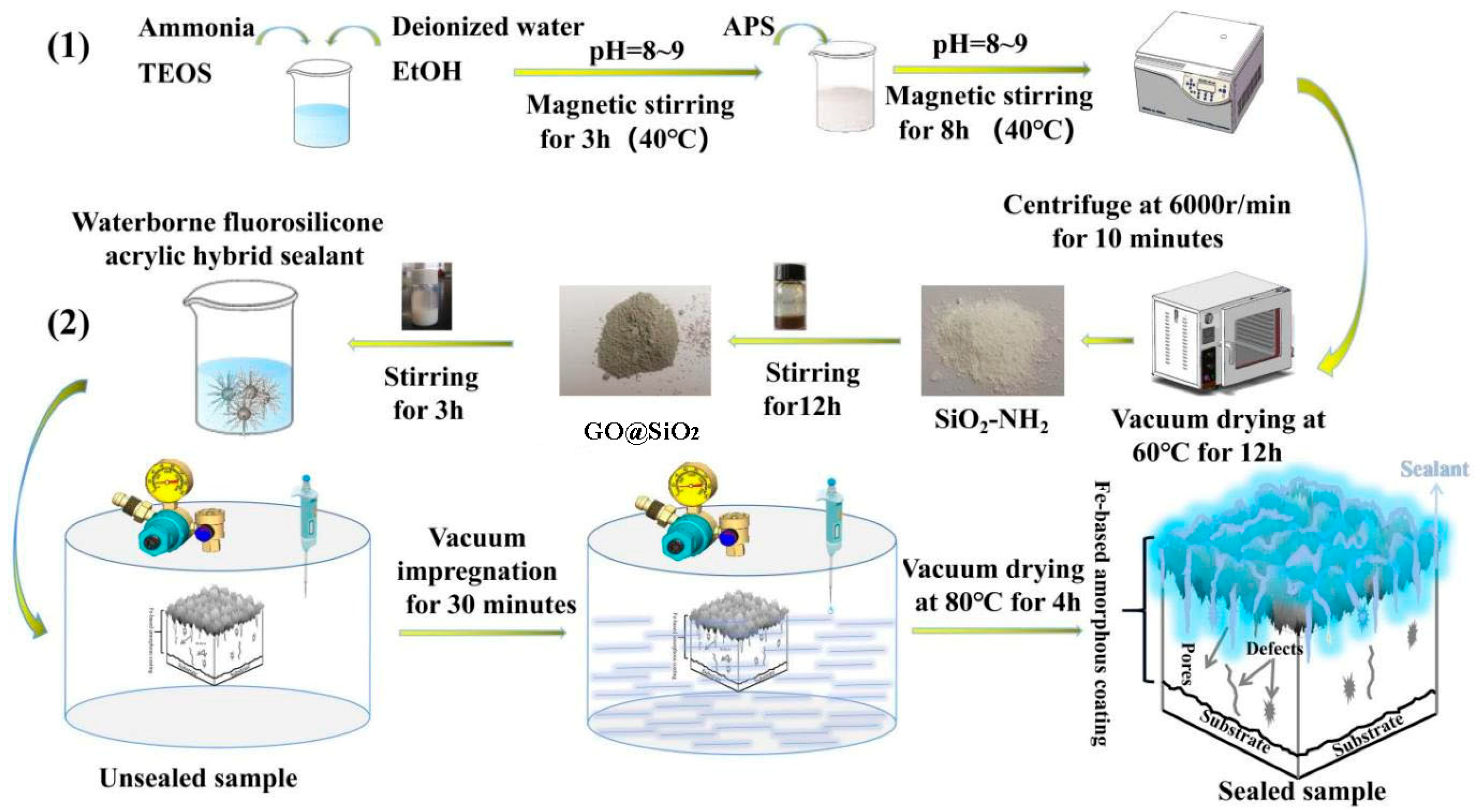
2.2. Preparation of Fe-Based Amorphous Coating

Fe-based amorphous coatings were prepared on Q235 steel using a Preair/Tafa 3710 plasma spray system. The elemental composition of amorphous powders is listed in Table 1. For the detailed preparation, refer to past studies [10].

2.3. Preparation of Graphene Modified Waterborne Acrylic Sealant

2.3.1. Preparation of GO@SiO2

A detailed description of the preparation process for GO@SiO2 can be found in Figure 1 (1). Firstly, absolute ethanol 40 mL, deionized water 4 mL and ammonia water 2 mL were added to the beaker and magnetically stirred at 500 r/min for 10 min. TEOS 4 mL was added dropwise and stirring was continued for 1 h to obtain a milky white suspension. Secondly, APS 0.3 mL was added dropwise to the suspension and stirring was continued for 8 h. A white powder SiO2-NH2 was obtained by centrifuging the suspension at 6000 r/min for 10 min and vacuum drying it for 12 h at 60 °C. Thirdly, take SiO2-NH2 0.1 g, 0.3 mL of GO dispersion with a concentration of 5 mg/mL, and 100 mL of deionized water for ultrasonic dispersion for 30 min and continue stirring for 12 h. The suspension was centrifuged to obtain wet GO@SiO2. Subsequently, to obtain the GO@SiO2 nanocomposite, the gray product was dried in a vacuum drying oven at 60 °C for more than 12 h.

2.3.2. Preparation of Graphene Modified Waterborne Acrylic Sealant (WFS)

The waterborne fluoro-silicone modified acrylic emulsion was prepared by semi-continuous dropwise addition. The typical preparation process was as follows: Firstly, BA 10 g, Bt 5 g, TFEMA 0.9 g, VTES 0.9 g, BMA 6.9 g, SBMA 1 g, SDS 0.27 g, Triton X-100 0.3 g, deionized water 46 g were added to the flask, and emulsified at high speed to obtain a milky white suspension, which was named component A. Secondly, mix deionized water 20 g and KPS 0.3 g into a four-necked flask with a condensing device, named component B. Bubble N2 for 30 min to remove air from the flask. Thirdly, pour two-thirds of component A into component B and start stirring (500 r/min), the temperature of the water bath is slowly raised from room temperature to 80 °C, and the flask is kept for 2 h after the obvious blue light phenomenon occurs. Fourth, the remaining component A was slowly added dropwise to the flask within 30 min, and the reaction was terminated after holding the temperature for 2 h. The temperature of the system was cooled to room temperature, and pH = 7~8 was adjusted with NaHCO3 to obtain a waterborne acrylic emulsion (WFE) with a solid content of 27 ± 3%.
The prepared GO@SiO2 nanocomposite was added to the emulsion at a mass ratio of 0.3‰, 1‰, 3‰ and stirred at high speed for 3 h to obtain a graphene modified waterborne acrylic sealant (WFS). The fluidity of the sealant is adjusted by thickener to achieve the appropriate viscosity (11 ± 2 Pa·s, 25 °C).

2.3.3. Detailed Sealing Process of Fe-Based Amorphous Coating

A combination of ultrasonic excitation and vacuum sealing was used to promote more waterborne hybrid sealant deposition into through-defects. Before sealing, the samples were sonicated in absolute ethanol for 30 min and rinsed with acetone to remove fillers deposited on the surface of the coating and in the pores. The samples were dried in an oven at 60 °C for 12 h before use. Figure 1 (2) illustrates a typical sealing process. Firstly, under vacuum, samples were placed in a sealed jar. Secondly, slowly inject the hybrid sealant into the sealed jar via a syringe. Then, the sealed jar was transferred to an ultrasonic transmitter and sonicated for 30 min. Thirdly, transfer the sample to an oven at 80 °C for 4 h, and continue curing for 48 h at room temperature. All samples treated with waterborne hybrid sealant were named WFE, WFS-0.3‰, WFS-1‰ and WFS-3‰, respectively. In addition, an unsealed sample (0#) was added as a control group. The main acronyms used in the present paper are listed in Table 2.

2.4. Characterization

The particle size of the latex particles was measured by a laser particle sizer (Model: Malvern Mastersizer 2000 Britain, Haan/Duesseldorf). The emulsion composition was analyzed by Fourier transform infrared spectroscopy (FTIR Model: Thermo Scientific NicoletiS20 USA, Waltham) in the range of 400~4000 cm2. Thermogravimetric analysis (TGA Model: TGA 5500 Germany) investigated the heat resistance of the emulsion. The glass transition temperature of the emulsion was evaluated by Cryogenic Differential Scanning Calorimeter at −80~200 °C. (Model: TA Discovery DSC 250 USA). The bonding of nanocomposite GO@SiO2 was analyzed by X-ray diffractometer (XRD Model: Rigaku Ultima IV Japan), thermogravimetric analysis (TGA Model: TGA 5500 Germany) and X-ray electron spectroscopy (XPS Model: Thermo Scientific ESCALAB 250Xi USA, Waltham), respectively. The morphology of the nanocomposite GO@SiO2 was obtained by Transmission Electron Microscopy (TEM Model: FEI Tecnai F20 USA). The crystal form and morphology of Fe-based amorphous powder and As-sprayed coating were obtained by X-ray diffractometer (XRD Model: Rigaku Ultima IV Japan) and scanning electron microscope (SEM Model: JSM-7800F Japan). The 3D X-ray scanning technology (GE Vtomexs CT USA) technology was used to characterize the internal microstructure of the coating, especially the distribution and change of porosity before and after sealing.
The long-term resistance behavior and anti-corrosion mechanism of sealed and unsealed samples were recorded using potentiodynamic polarization curves and electrochemical impedance spectroscopy. Immerse the sample in a salt solution (3.5 wt% NaCl solution, the salt solution is regularly updated) and record the polarization curve and AC impedance data of the sample through an electrochemical workstation system [10]. The test conditions are as follows: the scanning range is −1.5 to + 1.5 V and the scanning speed is 1 mV/s. To ensure the authenticity of the experimental results, each test was repeated three times and the average value was taken as the final result.
Cl has a strong breakdown ability to penetrate the passive film of the Fe-based amorphous coating. Once the passive film is broken down, the protective ability of the coating will be significantly reduced. Therefore, the long-term barrier ability (24~672 h) of the waterborne hybrid sealant to Cl was explored by an immersion experiment. The sealed and unsealed samples were immersed in a salt solution (3.5 wt% NaCl solution) and the failure modes of the hybrid sealant were observed using the SEM-EDX (Model Hitach S-3400N Japan) system. Before testing, the sample is cut from the center and polished with sandpaper.

3. Results and Discussion

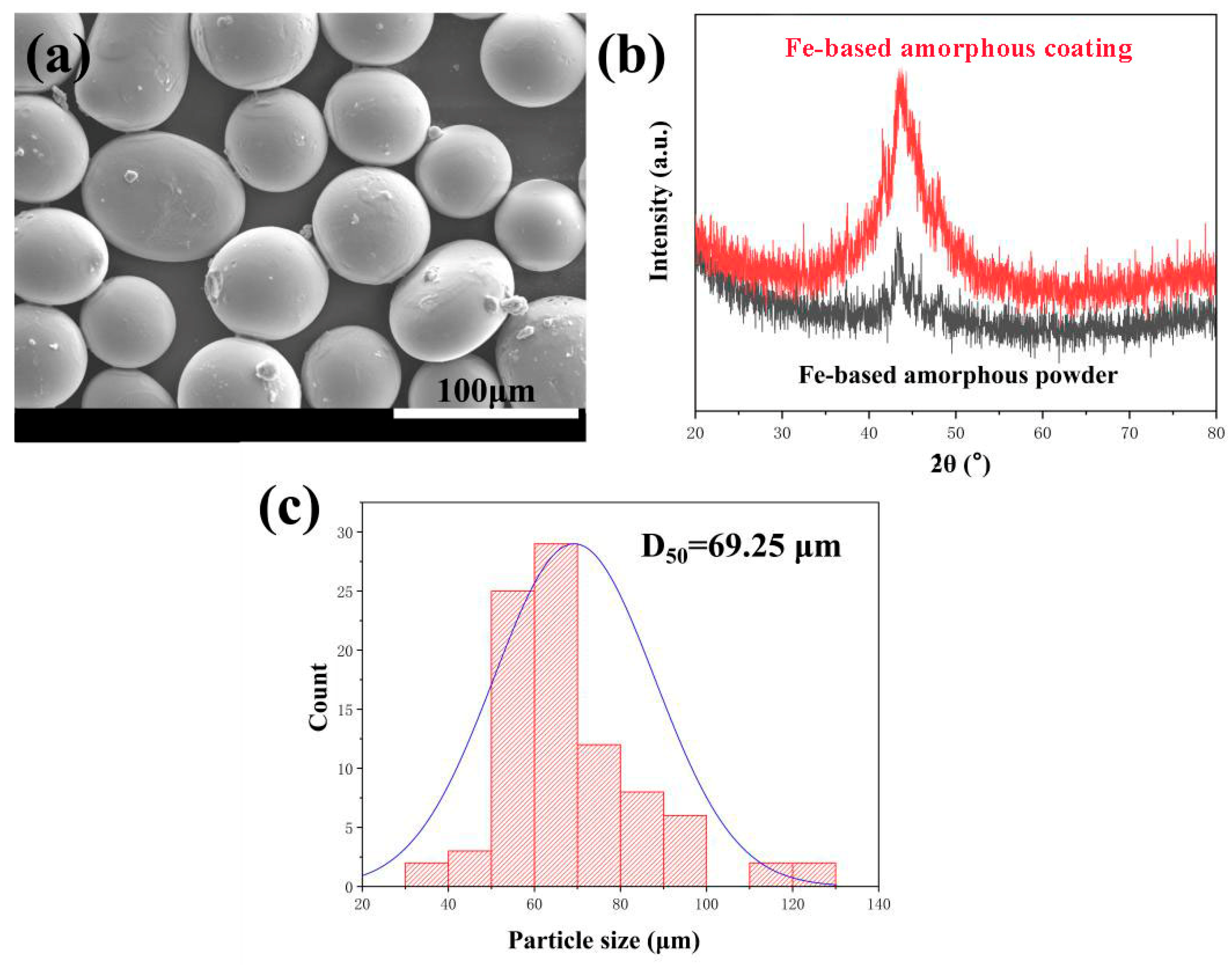
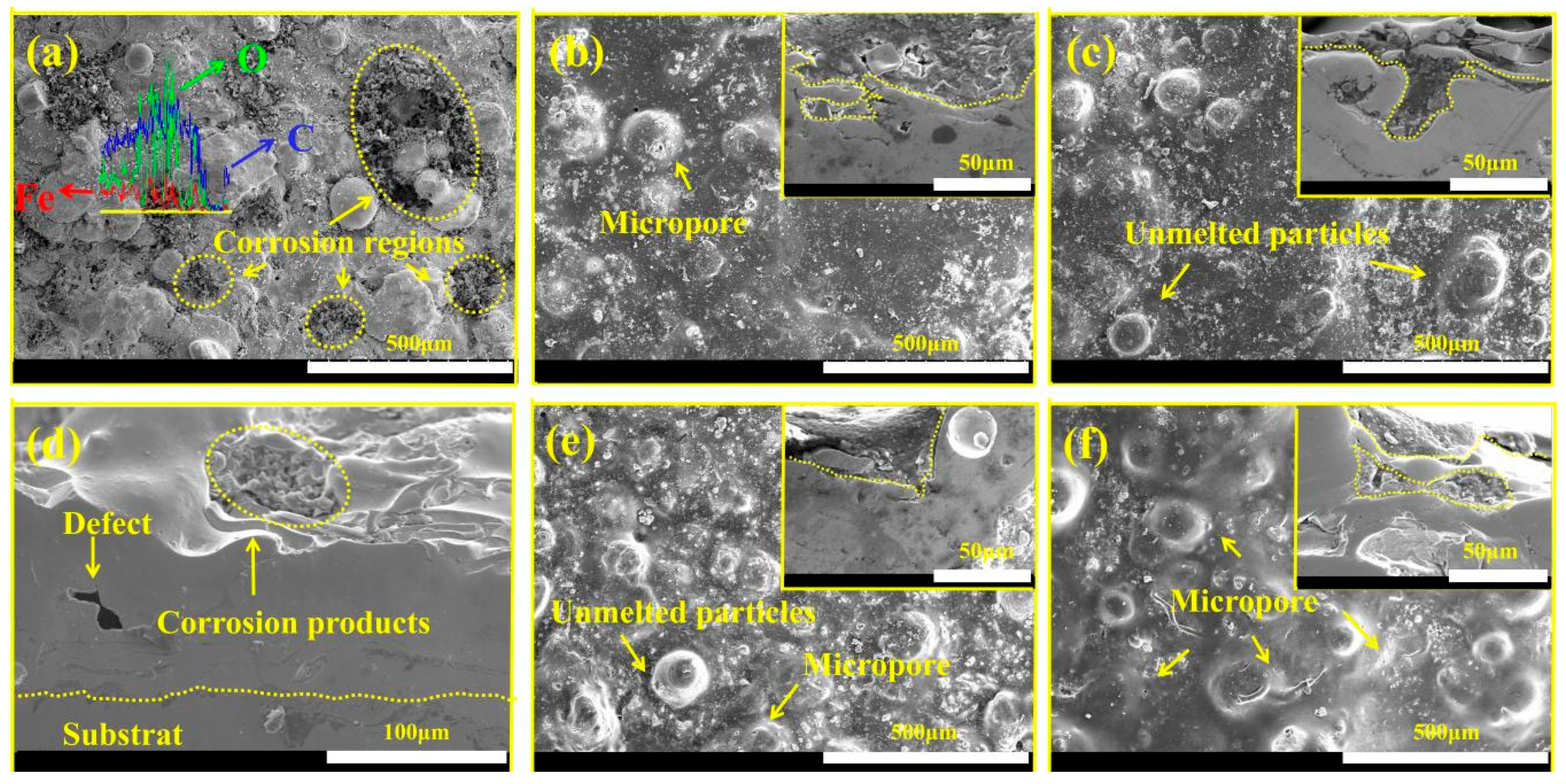
3.1. Fe-Based Amorphous Coating Characterization

The particle size and microstructure of Fe-based amorphous powders are closely related to the formation of coating defects. Generally speaking, the larger the particle size of the powder, the larger the pores tend to be during the deposition process. It can be seen from Figure 2a,c that the powder structure is spherical or elliptical, and the average particle size is 69.25 μm. A reasonable particle size distribution facilitates the formation of high-quality coatings. Figure 2b shows the XRD patterns of the Fe-based amorphous powder and the As-sprayed coating. It can be seen from the plot that the powder and coating present a broad reflex peak at 2θ = 44°, which is a typical Fe-based amorphous structure [29,30]. It is worth noting that the characteristic peaks of the sprayed coating are relatively sharp, indicating that a crystallization process occurred simultaneously during the high-temperature spraying process. It cannot be ignored that the noise masks the crystallization process to a certain extent. XRD results show that we have successfully prepared qualified Fe-based amorphous coatings.

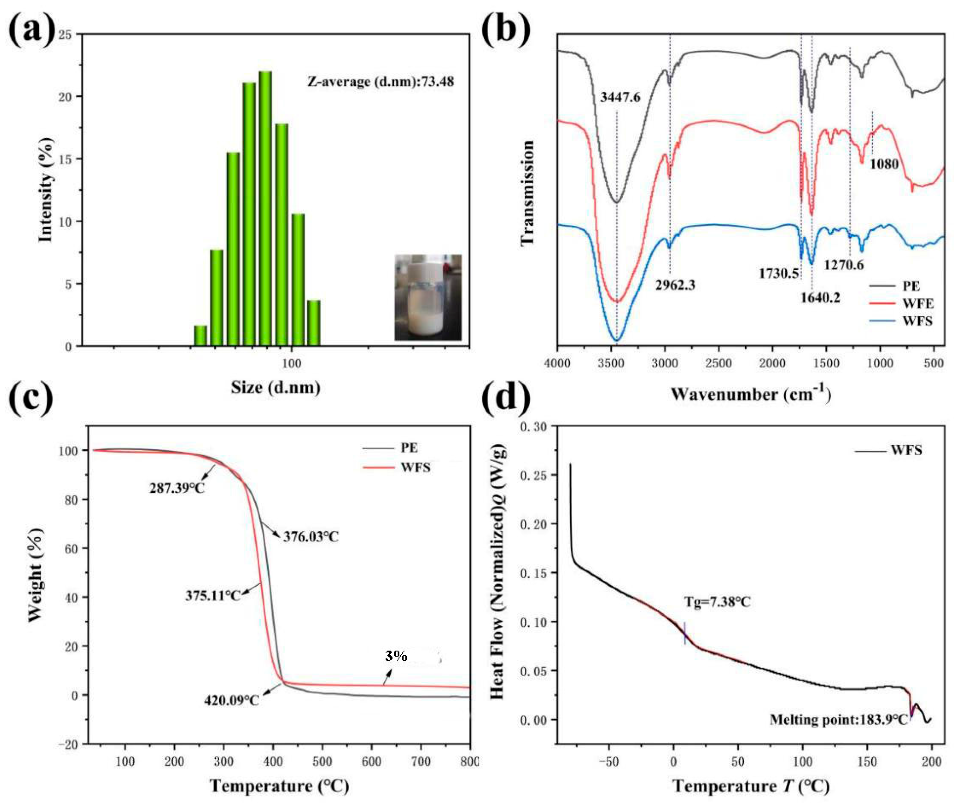
3.2. Natural Properties of WFE and WFS

The properties of WFE were characterized, and the results are shown in Figure 3. It can be seen from Figure 3a that the particle size of WFE is mainly distributed below 100 nm. Figure 3b shows the FTIR spectra of pure acrylic emulsion (PE) and waterborne acrylic emulsion (WFE). The O-H stretching vibration peak at 3447.6 cm−1 belongs to the water molecule, while the adsorption peak at 2962.3 cm−1 is caused by the stretching vibration of the C-H bond. The absorption peak at 1730 cm−1 is the characteristic absorption peak of the double bond of C=O, indicating that the product is mainly acrylate [31]. For vinyl, the double bond at the end of the C=C-H olefin double bond will have a strong absorption peak at 3075~3090 cm−1, but it is not recognized, indicating that C=C has undergone a polymerization reaction. In curve WFE, the absorption peak at 1080 cm−1 is attributed to the characteristic absorption peak of Si-O-Si, indicating that VTES has been grafted into the molecular chain [32]. In curve WFS, the characteristic absorption peak at 1270.6 cm−1 belongs to the C-F stretching vibration, indicating that TFEMA has been successfully grafted into the molecular chain. Excellent heat resistance is crucial to the service of resin in the atmospheric environment, especially in marine environment. Thermogravimetric analysis (Figure 3c) indicated that PE and WFS reached maximum decomposition rates at 376.3 °C and 375.11 °C, respectively. After 450 °C, a small amount of residual WFS originates from silicone, which is consistent with the FTIR results. Cryogenic Differential Scanning Calorimeter was used to evaluate the film-forming properties of WFS in the atmospheric environment. As shown in Figure 3d, the molecular chains begin to relax significantly at around 7.38 °C, indicating that WFS has good film-forming properties at room temperature. The splitting peak at 183.9 °C indicates that WFS is in a molten state at this time.

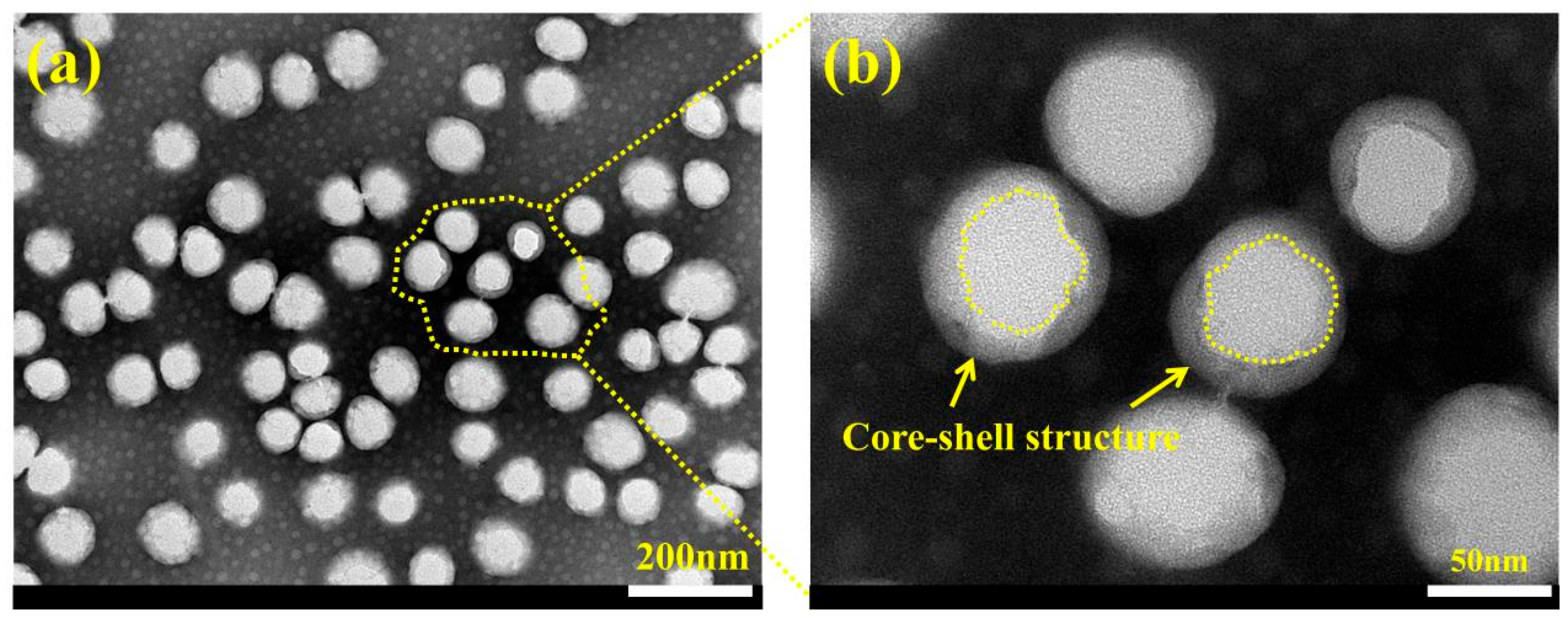
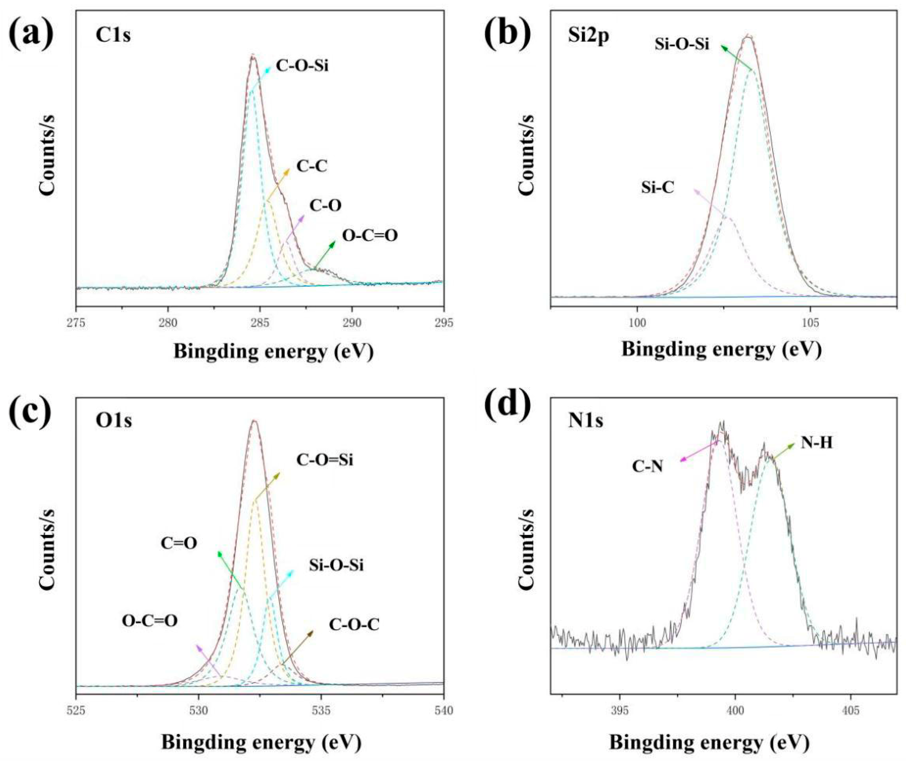
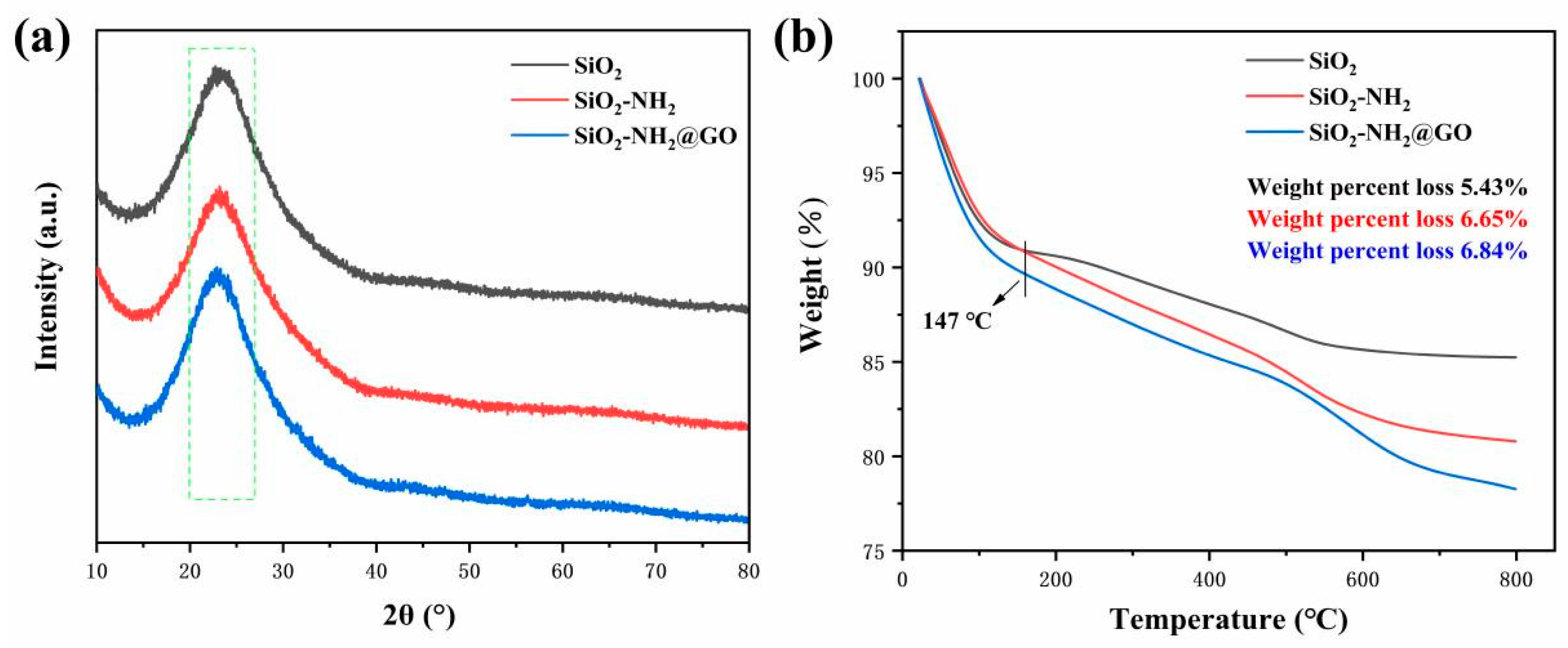
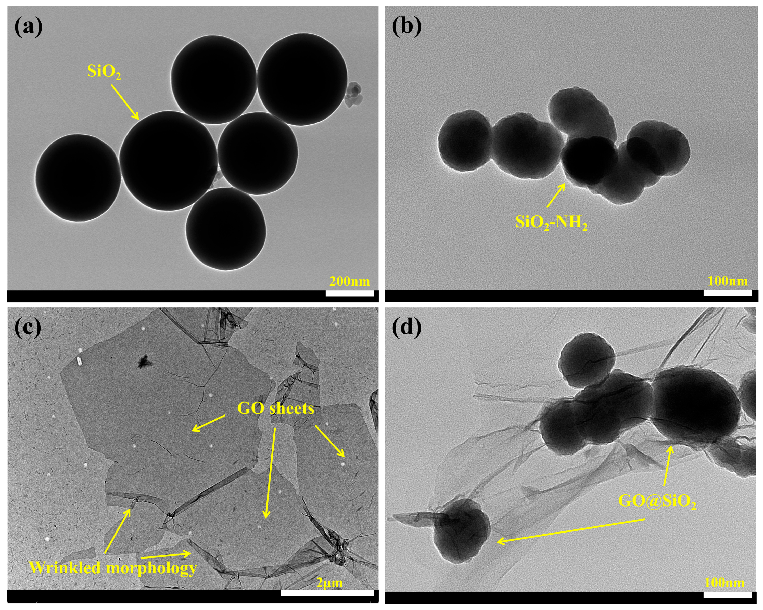
3.3. Characterization of Morphology and Microstructure of WFE and GO@SiO2

The morphologies of the emulsions diluted in deionized water were observed by TEM, as shown in Figure 4. The particle size of WFS prepared by the semi-continuous feeding method is below 100 nm, which is consistent with the test results of the particle size analyzer. After magnifying Figure 4a, it can be clearly seen that the latex particles exhibit a typical core-shell structure. In the early stage of emulsion preparation, acrylate monomers and part of fluoro-silicone monomers were added to form macromolecular polymers and used as the core. Subsequently, the addition of organosilicon and organofluorine monomers can greatly improve the utilization of functional monomers. This polymerization method helps to reduce the surface energy of the sealant and increase its corrosion resistance.
The valence states of the GO@SiO2 were determined by XPS. The signal peaks of different elements were fitted by Gaussian fitting to obtain the bonding results on different orbitals. Figure 5a shows that the Gaussian fitting peaks at 287.8 eV, 286.4 eV, 284.7 eV, 285.2 eV on the C1s orbital belong to the characteristic signal peaks of O-C=O, C-O, C-O-Si, C-C. Figure 5b is the Gaussian fitting result of Si2p. At 103.3 eV, 102.6 eV correspond to the characteristic peaks of Si-O-Si and Si-C, respectively. The O1s located at 530.9 eV, 531.7 eV, 532.3 eV, 533.4 eV and 532.9 eV in Figure 5c correspond to O-C=O, C=O, C-O-Si, C-O-C and Si-O-Si, respectively, which are consistent with the C1s fitting results. The fitted peaks at 401.5 eV and 399.3 eV on the N1s orbital in Figure 5d correspond to the signal peaks of N-H and C-N, respectively, which indicate that SiO2-NH2 bonds with oxygen-containing groups on the surface of GO [32]. The XPS fitting results confirm that the GO@SiO2 with stable bonding has been successfully obtained.
The composition and crystal structure of the nanoparticles were further explored by XRD and thermogravimetry. The XRD patterns show that SiO2, SiO2-NH2 and GO@SiO2 exhibit similar amorphous structures. At 2θ = 22°, it is the broad reflex peak of SiO2. It is worth noting that GO could not be recognized by the instrument due to its low content (Figure 6a). Figure 6b is the thermogravimetric analysis result of the nanoparticles. The mass loss at 30~147 °C was derived from the volatilization of adsorbed water on the nanoparticle surface. The slowing of the mass loss rate at 147~600 °C was attributed to the decomposition of the organic components, with a mass loss percentage of 5.43% (SiO2) < 6.65% (SiO2-NH2) < 6.84% (GO@SiO2). Therefore, the GO modified by SiO2 is an amorphous and layer-by-layer cladding structure.
The morphology and size of the nanoparticles were observed by TEM, as shown in Figure 7. The particle size of SiO2 has uniformly distributed between 100~250 nm and presents a smooth spherical structure (Figure 7a). The morphology of APS-modified SiO2 is shown in Figure 7b, which is consistent with the report. Figure 7c shows the morphology of monolithic GO: ultrathin lamellar structure and some sheets appear wrinkled. The larger radial size of GO is conducive to the formation of a stable cladding structure. Figure 7d shows a typical cladding structure, in which nano-SiO2 is uniformly coated in sheet GO. Combined with the XPS, the stable bonding between SiO2 and GO surface is favorable for the composite to form a stable “labyrinth structure” in the matrix.

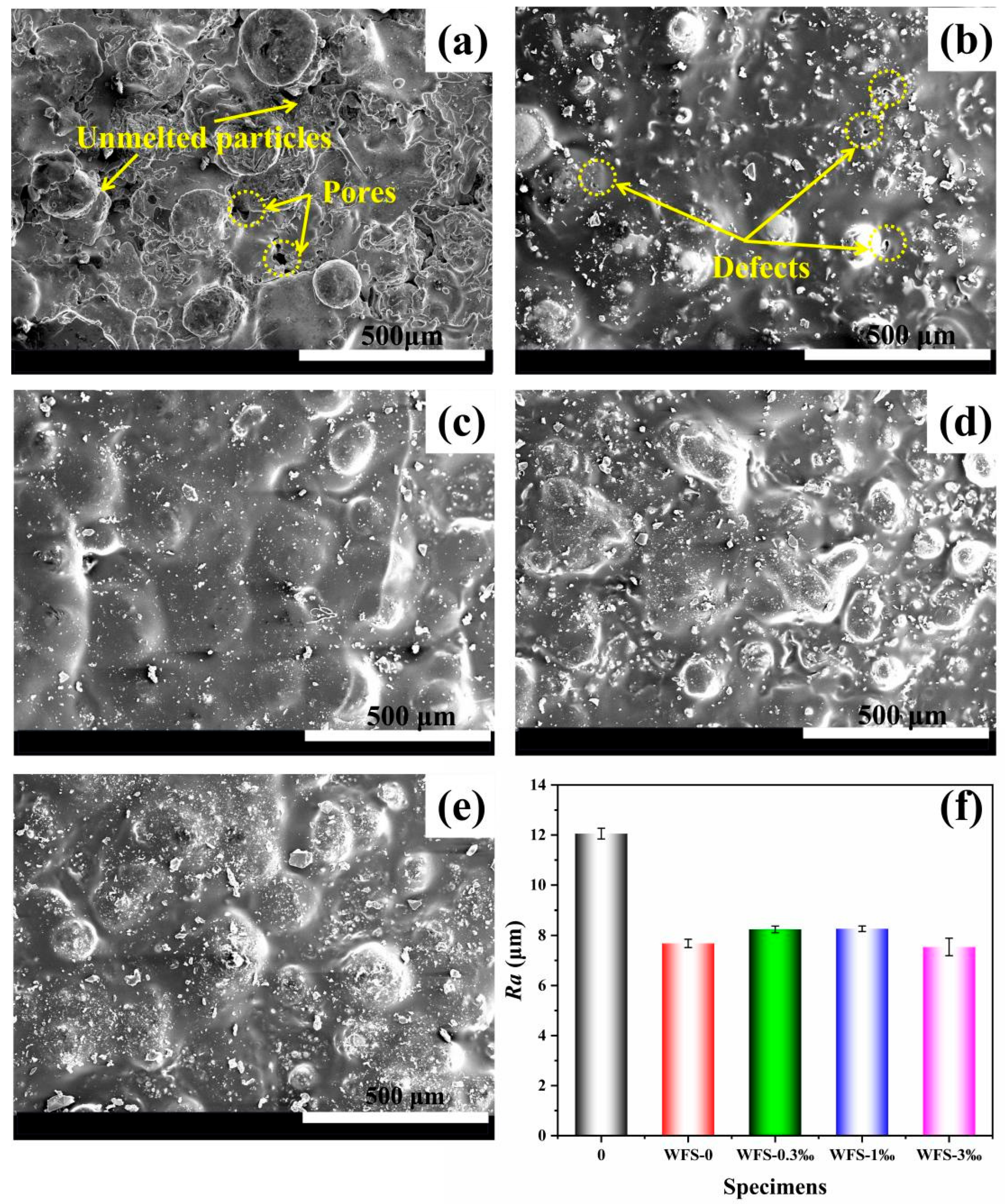
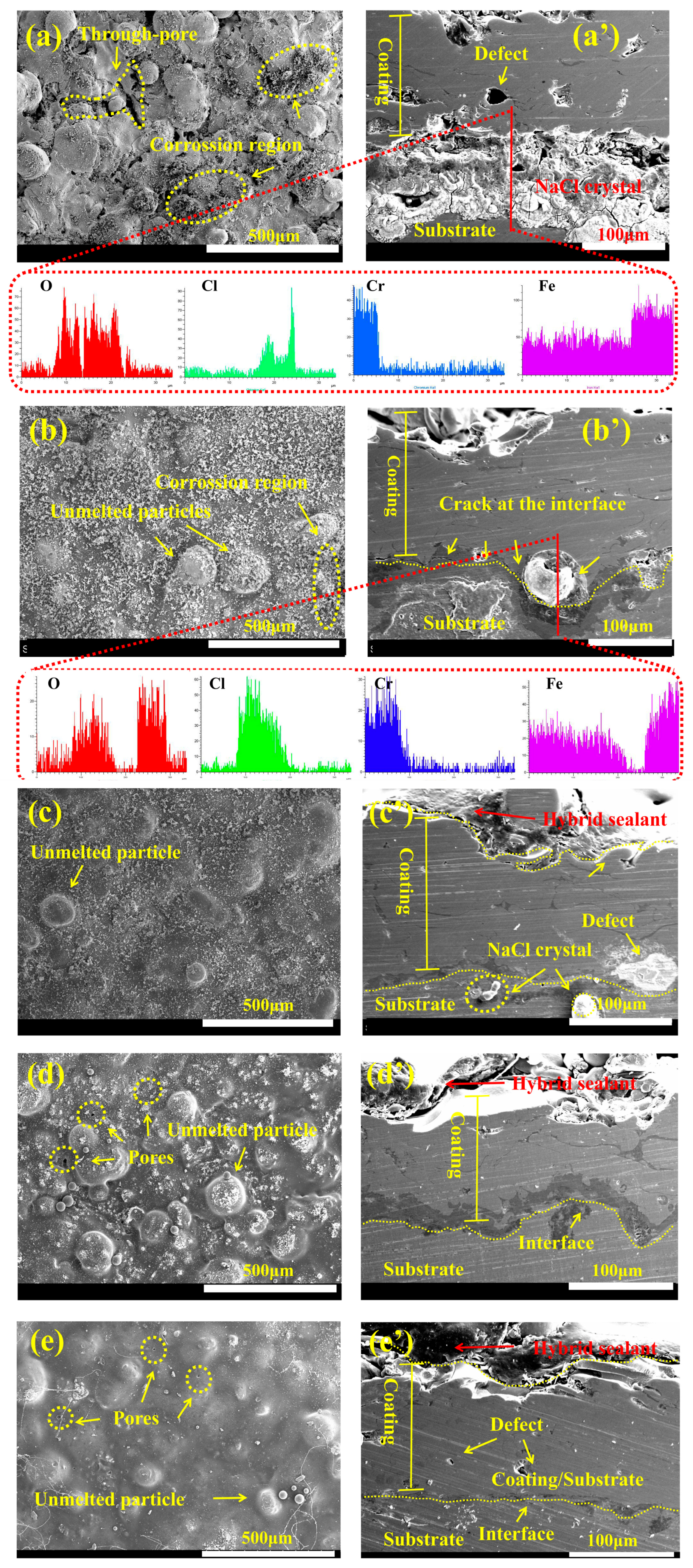
3.4. Research on the Sealing Performance of WFS

Top-view SEM images of the sample before and after the hybrid sealant treatment are shown in Figure 8. The microstructure of a typical Fe-based amorphous coating is shown in Figure 8a. Under the high-temperature plasma flow, the molten metal powder is continuously deposited on the substrate, so that the coating presents a layer-by-layer structure. Due to the inhomogeneous size of amorphous particles, the coating inevitably has a certain proportion of porosity and unmelted particles. The pore diameters are mainly distributed in the range of 30~50 μm, which is close to the previous conclusions. After the sealing treatment, almost all the pores are effectively blocked. It can be clearly seen from Figure 8b that the surface of the sealed sample (WFE) has a small number of porosity defects, probably because the sealant is not dense enough during the drying process. After adding GO@SiO2 (Figure 8c–e), the lamellar structure of GO has excellent tensile toughness to avoid defect formation and increase the compactness of WFS. In addition, the surface roughness of all coatings was tested, and the Ra value was significantly reduced after sealing treatment, which also means that the better flatness of the surface of the sealed coating can avoid the retention of corrosive media in the pores (Figure 8f).
To further explore the penetration performance of WFS on the coating, Figure 9 shows the cross-section SEM-EDX test results of samples treated with different hybrid sealants. The cross-section of Fe-based amorphous coating has a large number of open or closed micro-pores, especially the formation of a staggered and stacked structure on the surface of the coating will form a large number of corrosion channels. Corrosive media will destroy the coating along the channel and seed the substrate to corrode. It can be seen from the EDX characterization results in Figure 9 that a large amount of Fe elements has been identified (The blue area), while the red area represents the sealant. Especially in Figure 9b,c, a large amount of sealant penetrates into the micro-pores of the coating, preventing corrosive factors from penetrating into the pores. In addition, removing the air in the pores of the coating by vacuum treatment is beneficial to increase the interface area between the sealant and the coating. Consequently, EDX mapping demonstrated better sealing performance of WFS.
The pore distribution of the porous coating before and after sealing was analyzed by 3D X-ray scanning technology. Figure 10a,b are 3D reduction morphologies before and after sealing treatment, respectively. After the sealing treatment, the large-size pores are greatly reduced, indicating that the hybrid sealant is effective in sealing the pores of the coating both outer and inner. Figure 10c,d give more comprehensive and detailed data on the properties of hybrid sealants. The porosity began to decrease significantly at 160 μm away from the interface, indicating that the penetration depth of the hybrid sealant reached more than 160 μm, and the porosity decreased from 6% to 1% (the penetration depth of common organic sealants is within 100 μm). It can be seen from Figure 10e that, after sealing treatment, the pores with a diameter of more than 70 μm almost disappear, and the remaining pores are mainly distributed near the interface. In addition, the number of through-pores will also affect the penetration of the hybrid sealant, which is inevitable. From the sealing surface, cross-section and internal microstructure of the coating, the Graphene-modified waterborne acrylic sealant exhibits excellent sealing properties.

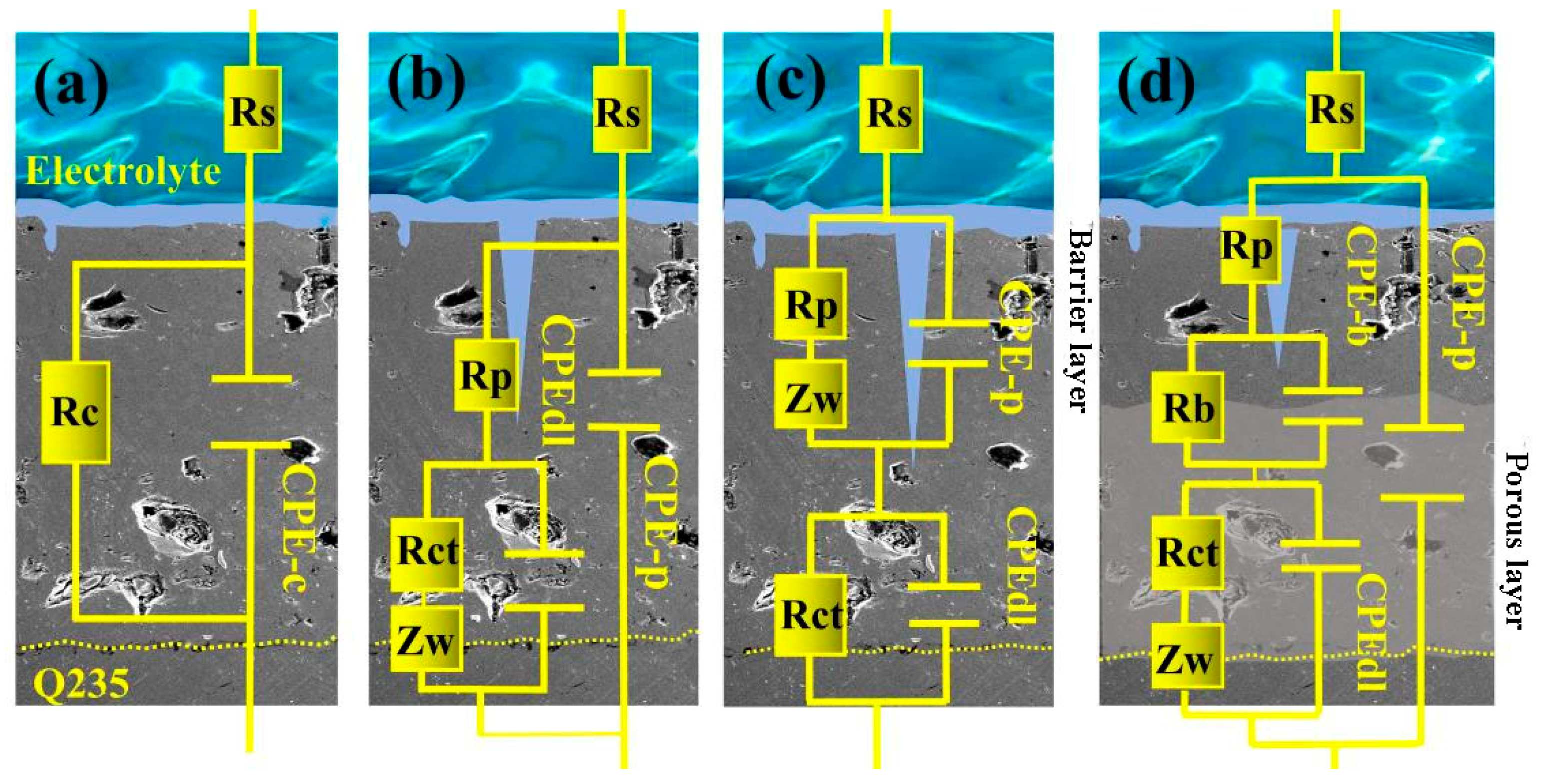
3.5. Research on Corrosion Resistance of the Sealed Coating

A strong self-passive property in the atmospheric environment is the key to the excellent corrosion resistance of Fe-based amorphous coatings. Therefore, it is essential to explore their passivation process in corrosive environments. The passive behavior of Fe-based amorphous coating in corrosive solution was investigated by potentiodynamic polarization, as shown in Figure 11. Ecorr, icorr, βa, βc, Epp, ip represent corrosion potential, corrosion current density, cathodic slope, anodic slope, primary passive potential and maintain passive current density, respectively. The anti-corrosion mechanism and failure process of the sealed sample can be analyzed by these key parameters. In addition, η represents the protection efficiency of the coating to the substrate, which is calculated as follows:
η   ( % ) = 100 %   ×   1 i c o r r , i i c o r r , b
In Equation (1) icorr,i and icorr,b values are corrosion current densities of the samples in the 3.5 wt% NaCl solution with and without the hybrid sealants, respectively [33].
Between −1 V to +1.5 V, all samples exhibited smooth passive regions, and the data of the polarization curves are shown in Figure 12. Due to the metastable structure existing on the surface of the amorphous coating and the intrusion of corrosion factors into the coating passive film, the passive region of the unsealed sample (0#) has obvious fluctuations, especially near Epp. On the contrary, the sealed samples exhibited a smoother passive region, indicating that the hybrid sealant can effectively resist the migration of corrosion factors into the coating. After the sealing treatment, the corrosion potential of the sample moved positively, and the corrosion current density also decreased by more than one order of magnitude. With the increase of the content of GO@SiO2, the corrosion resistance of the sealed samples increased significantly. The “barrier effect” of GO on small molecules and the “labyrinth effect” will prolong the time for the corrosive media to reach the substrate. The sealed samples maintained stable passivation, and the corrosion current density decreased significantly after soaking for 504 h. The △ip (passivation current density difference) of the sealed sample is much smaller than that of the unsealed sample, and the corrosion rate of the amorphous coating is extremely small at this time, which has a positive effect on the protection of the coating. When the anode potential continues to increase to the pitting potential, the passive film will be broke down, resulting in corrosion of the coating. In addition, the protective efficiency of the coating showed an upward trend with the increase of the GO@SiO2 content but decreased after immersion for 672 h, which was consistent with the changing trend of the corrosion current density. Obviously, the hybrid sealant can effectively promote the integrity of the passive of Fe-based amorphous coating.
EIS revealed the variation of the corrosion resistance of the samples with the salt immersion time, as shown in Figure 13. It can be observed that the shapes of the various Nyquist diagrams are significantly different, indicating that the corrosion resistance mechanism of the samples has changed. It is generally believed that a longer capacitive arc radius means better corrosion resistance [34]. Obviously, the modulus values of the samples differ by more than an order of magnitude before and after the sealing treatment, especially with the increase of the GO@SiO2, the impedance modulus value showed an upward trend. In the initial stage of immersion (0~48 h), the dense sealing layer blocked the pores of the coating and effectively prevented the diffusion of corrosion factors into the coating. Therefore, all the sealed samples showed good corrosion resistance. However, for the unsealed sample (0#), the corrosion factor would gradually diffuse to the coating/substrate interface along the corrosion channel and form a penetrating corrosion network, which eventually led to the failure of the Fe-based amorphous coating. After immersion for 168 h, the corrosion factors diffused into the sealing layer, and GO@SiO2 played a leading role in the corrosion resistance of the composite coating. WFS-1‰ and WFS-3‰ showed the best corrosion resistance, while WFS-0.3‰ had fewer nanofillers, so the corrosion resistance was not improved significantly. After immersion for 168~672 h, the sealed samples showed a typical Warburg diffusion resistance phenomenon. When the corrosive media is filled in the pores or inter-splat of the coating, it exhibits diffusion impedance behavior, and this “plugging effect” can block the diffusion of the corrosive media in a short time [35,36]. Furthermore, research shows that the high-frequency and low-frequency characteristics of the Bode impedance plot can reflect the response information of the porous layer and the barrier layer [37,38]. After immersion for different times, the modulus values of the sealed sample in both the low frequency and high frequency response regions are much larger than those of the unsealed sample, indicating that sufficient hybrid sealant penetrates into the pores and exhibits excellent sealing. Especially in the later stage of immersion, the WFS-3‰ has the best anti-corrosion performance.
Based on the basic analysis of Nyquist and bode diagram, fit the data to get the appropriate equivalent circuit diagram and place the appropriate electronic components in the correct position (Figure 14). These equivalent circuit diagrams include the following components: Rs is the solution resistance, Rc is the coating resistance, and Rb represents the dense barrier resistance in the coating [39]. Rp is the pore resistance, which represents the resistance of electric current through the pores, which is inversely proportional to the porosity of the coating and proportional to the pore length. The Rp value reflects the protective ability of the coating. CPE-c is a constant phase element that determines the capacitance of the coating. The calculation method is as Formula (2) [40].
Z C P E = 1 f 0 ( j × w ) n
where f0 is the admittance parameter and is related to the interface double-layer capacitance. w is the angular frequency, and j is the imaginary number. Rct and CPEdl represent the ease of electrochemical reaction at the corrosive liquid/substrate interface during immersion [41]. Moreover, a Warburg element (Zw) is used in the equivalent circuit diagrams Figure 14b–d. Warburg diffusion impedance is used to describe the semi-infinite diffusion process in the seal coating [42]. Equivalent circuits (a) and (c) are used to fit sample 0#. Equivalent circuits (b) and (c) are used to fit sample WFE. Equivalent circuit (c) is used to fit the sample WFS-0.3‰. Equivalent circuits (b) and (d) are used to fit samples WFS-1‰ and WFS-3‰. All fitted data are listed in the Supplementary Data. The Rs value is independent of the material itself and the variation is negligible. For sample 0#, the values of Rc and Rct decreased gradually with the prolongation of immersion time, indicating that the corrosion factors diffused into the coating and formed galvanic corrosion at the coating/substrate interface. This corrosion spreads along the Cr-depleted zones in the coating to the surrounding zones, rapidly causing the coating to fail. The Rp value for the sealing samples is a key parameter representing how well the hybrid sealant seals the coating and its long-term corrosion resistance. After sealing treatment, the Rp value rose by more than an order of magnitude. After immersion for 168 h, Rp tended to be stable, especially since the values of WFS-1‰ and WFS-3‰ are almost unchanged. The above results fully demonstrate that the hybrid sealant is sufficient to seal the defects of the coating and achieve the effect of isolating the corrosive media. The GO@SiO2 plays a key role in promoting the long-term corrosion resistance of the hybrid sealant. Generally speaking, the larger the Rct, the greater the impedance modulus, and the better the corrosion resistance of the coating [43].
From the bode impedance diagram in Figure 13, the modulus value of the sealed samples at low frequencies is generally higher than that of the unsealed sample, which is consistent with the Rct value. In the initial period of immersion (0~48 h), the Rct value of the sealed samples was two orders of magnitude higher than that of the unsealed sample. After immersion for 672 h, as the content of GO@SiO2 increased, the Rct values of samples WFS-1‰ and WFS-3‰ were 2104 Ω·cm2 and 2982 Ω·cm2, respectively. This indicates that the lamellar nanofiller has more advantages in long-term corrosion protection. During the migration process of corrosive factors or hybrid sealants, the electrochemical corrosion model of the coating changes, and the combined structure of the dense barrier layer and porous layer replaces the single porous structure (Figure 14d). Studies have shown that the barrier layer has obvious barrier properties to Cl and water molecules [44]. Therefore, the Rb value represents the resistance of hybrid sealants to Cl or water molecules. These electrochemical observations indicate that the hybrid sealant has excellent sealing properties, which can significantly extend the service life of the coating.
To more realistically simulate the service environment of the sealed samples, the samples were immersed in a salt solution to investigate the failure modes of hybrid sealants. Figure 15 and Figure 16 show the corrosion morphology images of the samples after immersion for 168 and 672 h, respectively. For sample 0#, after immersion for 168 h, a large number of fluffy corrosion products appeared on the coating surface (Figure 16a). Once corrosion occurs, the corrosion rate increases significantly. Corrosion products will fill in the surface pores, and as the corrosive media erodes, the corrosion behavior gradually expands into adjacent surface pores and forms larger through-pores, which is very detrimental to the coating. EDX characterization was done in the rusted zone, and the Fe, C and O elements were identified separately. The Fe content gradually decreased with the expansion of the corrosion zone, while the C and O element contents showed an upward trend, which was because a large amount of fluffy Fe oxides were produced in the corrosion zone, and the Fe element was difficult to identify. At this time, the coating is dissolved and chemically reacted. Equation (3)
F e F e 2 + + 2 e        
O 2 + 2 H 2 O + 4 e 4 O H
F e 2 + + 2 O H + 3 F e ( O H ) 2 + O 2 4 F e O O H + 2 H 2 O    
2 F e + O 2 + 2 C r 2 O 3 2 F e C r 2 O 4
A redox reaction (Equation (4)) occurs in the cathode region and OH is generated. Then it forms precipitates (Equation (5)) with Fe2+ and accumulates in the pores. Studies have shown that the corrosion process will generate a large amount of FeCr2O4 and form a large number of Cr-depleted zone to promote the formation of pitting corrosion (Equation (6)). The cross-section SEM image (Figure 15d) was obtained by cutting the immersed sample in the middle and polishing. It is observed from the cross-section that the coating/substrate interface maintains a good adhesion effect, indicating that sample 0# still maintains a good protective effect on the substrate at this time. However, the presence of large amounts of rust products in large pores or cracks indicates that corrosion channels have formed. Figure 16b,c,e,f are the corrosion morphologies of WFE, WFS-0.3‰, WFS-1‰ and WFS-3‰, respectively. There is no obvious damage that has occurred to the sealed samples from the top view SEM images. As the content of GO@SiO2 increases, the sealant surface tends to be smooth, which indicates that the nanofiller effectively increases the density and corrosion resistance. However, there are a few pin-hole defects on the surface of WFE corresponding to drying cracks or inhomogeneous thickness. The cohesive strength of the hybrid sealant was enhanced after adding GO@SiO2, thereby reducing pin-hole defects. The hybrid sealant/coating interface maintained good adhesion from the cross-section of the samples. The characteristic rough surface of Fe-based amorphous coatings provides abundant anchoring points for the hybrid sealant and promotes the formation of numerous mechanical interlocking structures, which will significantly increase the adhesion [9]. GO has a considerable radial area, which is beneficial to increase the interfacial area to form a dense 3D network structure. Subsequently, reducing defects in the hybrid sealant promotes adhesion strength [45].
Figure 16 is the corrosion morphology SEM-EDX test result of the samples immersed for 672 h. In Figure 16a, it is clearly observed that the corrosion region on the surface of sample 0# expands, and the wire crack expands into large-diameter through-pores. At this time, the corrosive media entered the coating/substrate interface and corroded, which was verified by the SEM image of the cross-section (Figure 16a’). EDX scanning revealed the formation of a large number of white crystals at the coating/substrate interface, and O, Cl, Cr and Fe elements were identified, indicating that Cl had passed through the coating and reached the coating/substrate interface. Cl has a very strong destructive effect on the passive film, so the coating has completely failed on the substrate. The top view SEM image of the sample WFE (Figure 16b) shows that a small corrosion region is observed, indicating that the sealant has been partially peeled off, and the corrosive media begins to rapidly diffuse to the coating/substrate interface. Figure 16b’ shows similar results to sample 0#, but only a few white crystals appear at the interface. Obvious cracks at the interface were observed, indicating that the coating was in failure mode. After adding GO@SiO2, the samples showed superior corrosion resistance. In the top view SEM image of the sample, there is almost no rust phenomenon and the surface is smooth and dense, but there are also a few pin-hole defects (WFS-1‰ and WFS-3‰). The hybrid sealant shows corrosion cracking at the unmelted particles, which is consistent with the previous research results. Viewed from the cross-section, white crystals also appeared at the coating/substrate interface of the sample WFS-0.3‰, indicating that fewer nanofillers could not achieve better Cl isolation, but no obvious cracks were found at the interface. We also observed that the hybrid sealant remained tightly adsorbed in the pores, blocking the channels for the diffusion of corrosive media, which is closely related to the vacuum sealing process. In sharp contrast to sample WFS-0.3‰, the sample WFS-1‰ and WFS-3‰ did not have any corrosion or Cl infiltration at the interface. From the above analysis, it can be concluded that the waterborne hybrid sealant is sufficient to seal coating defects, and GO@SiO2 can effectively prevent the diffusion of Cl and significantly improve the integrity of the coating passive film. It has important application value in thermal spray coating protection.

4. Conclusions

  • An eco-friendly graphene modified waterborne acrylic sealant (WFS) for sealing Fe-based amorphous coatings was successfully prepared. The sealant has good film-forming properties and excellent heat resistance, which ensures the stable quality of the hybrid sealant during service.
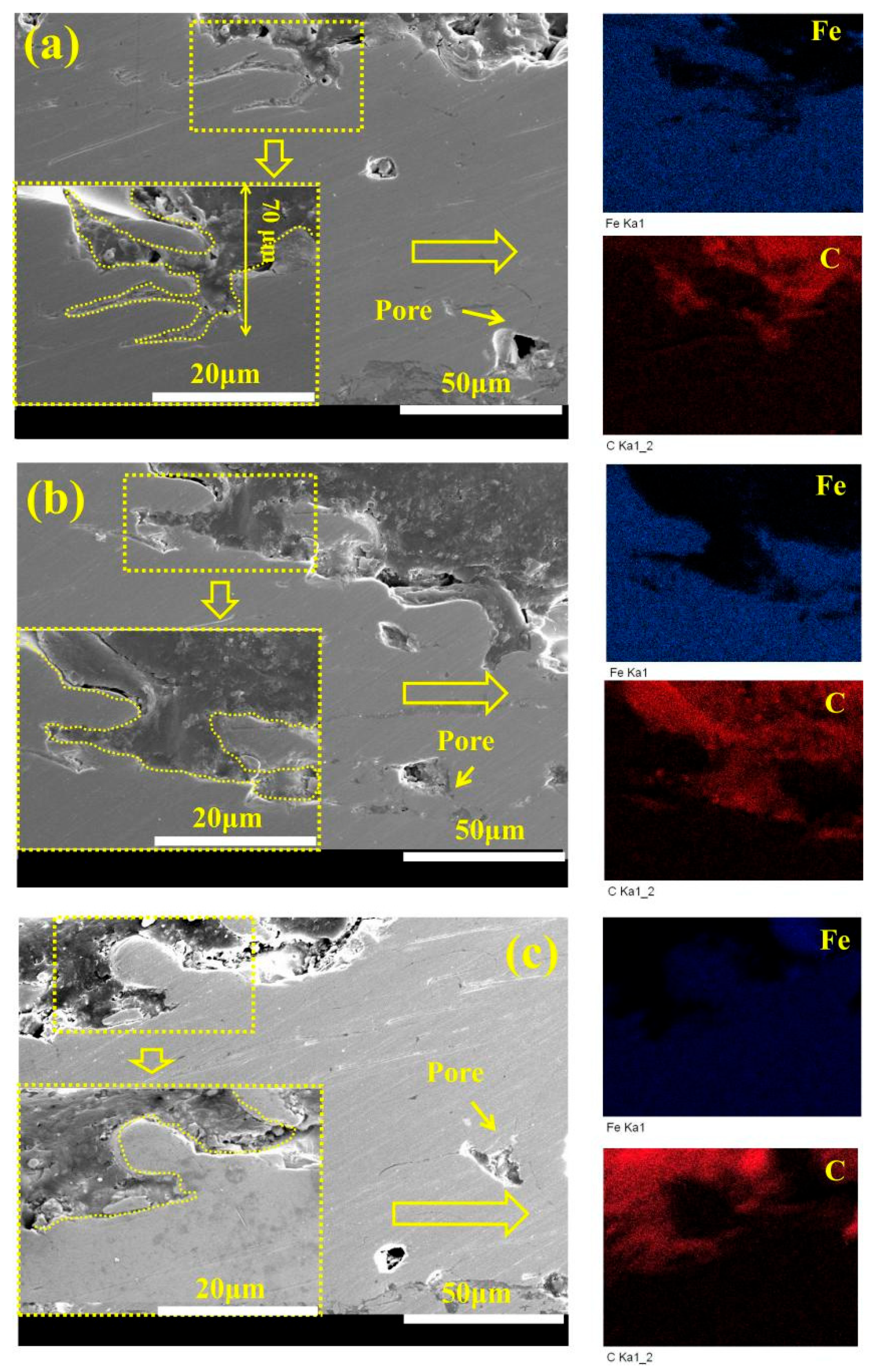
  • The combination of ultrasonic immersion and vacuum sealing can effectively promote the penetration of the hybrid sealant into coating defects and form a three-dimensional radial network sealing structure, which significantly improves the compactness of the coating. The 3D scanning technology showed that the penetration depth of the hybrid sealant reached 160 μm.
  • GO@SiO2 can significantly improve the cohesion strength of Fe-based amorphous coatings and increase the adhesion at the coating/substrate interface. With the addition of GO@SiO2, the pinhole phenomenon on the surface was significantly reduced.
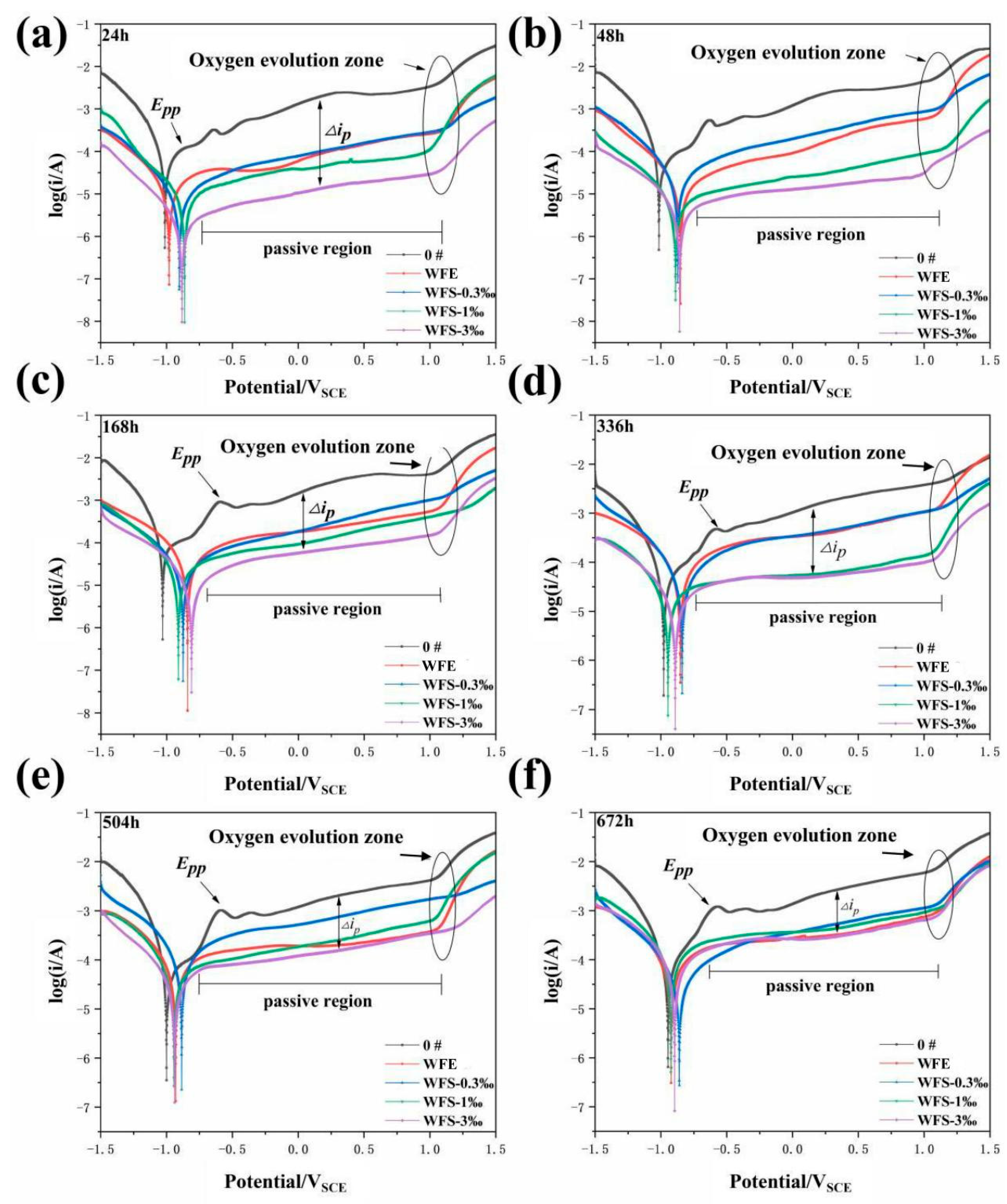
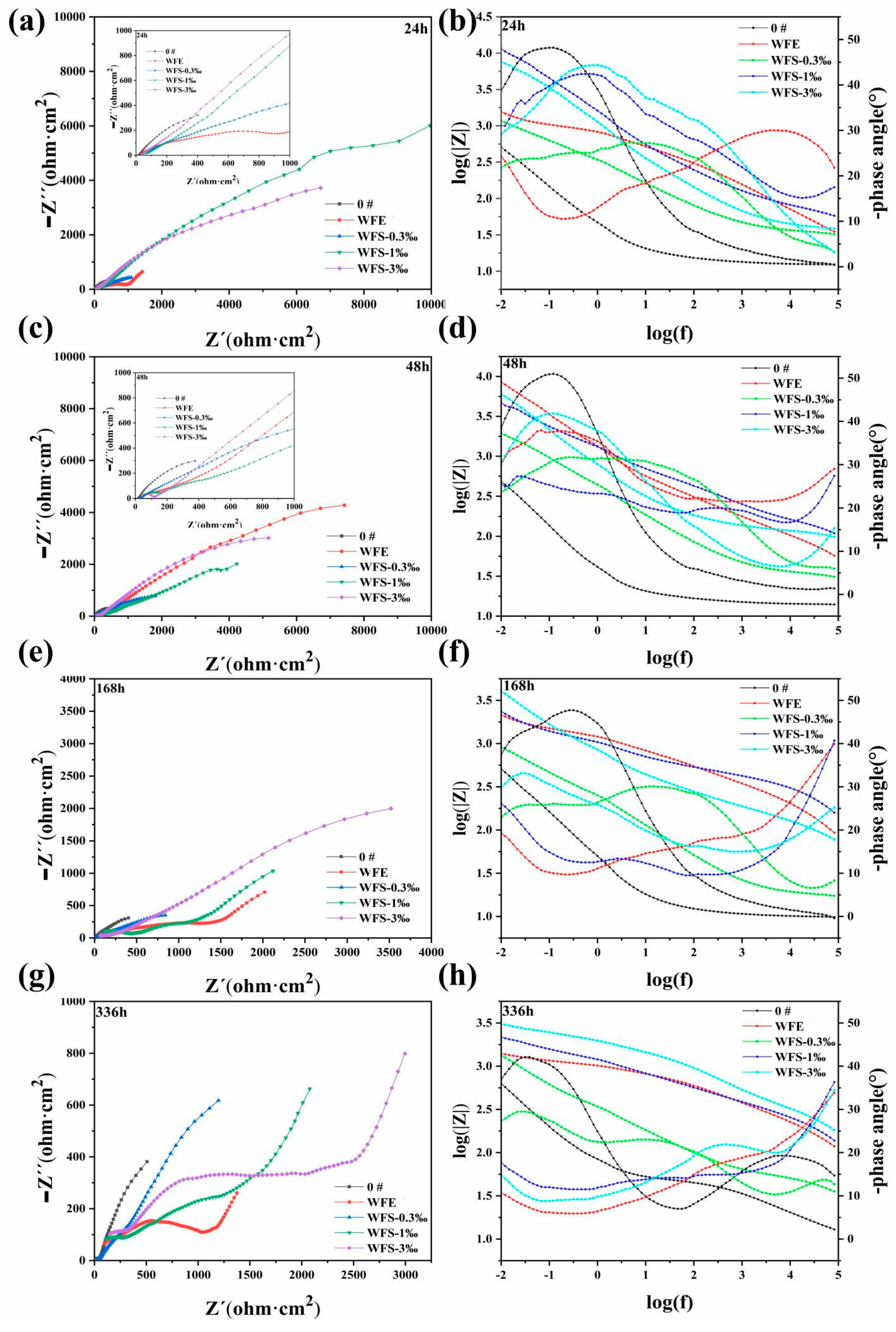
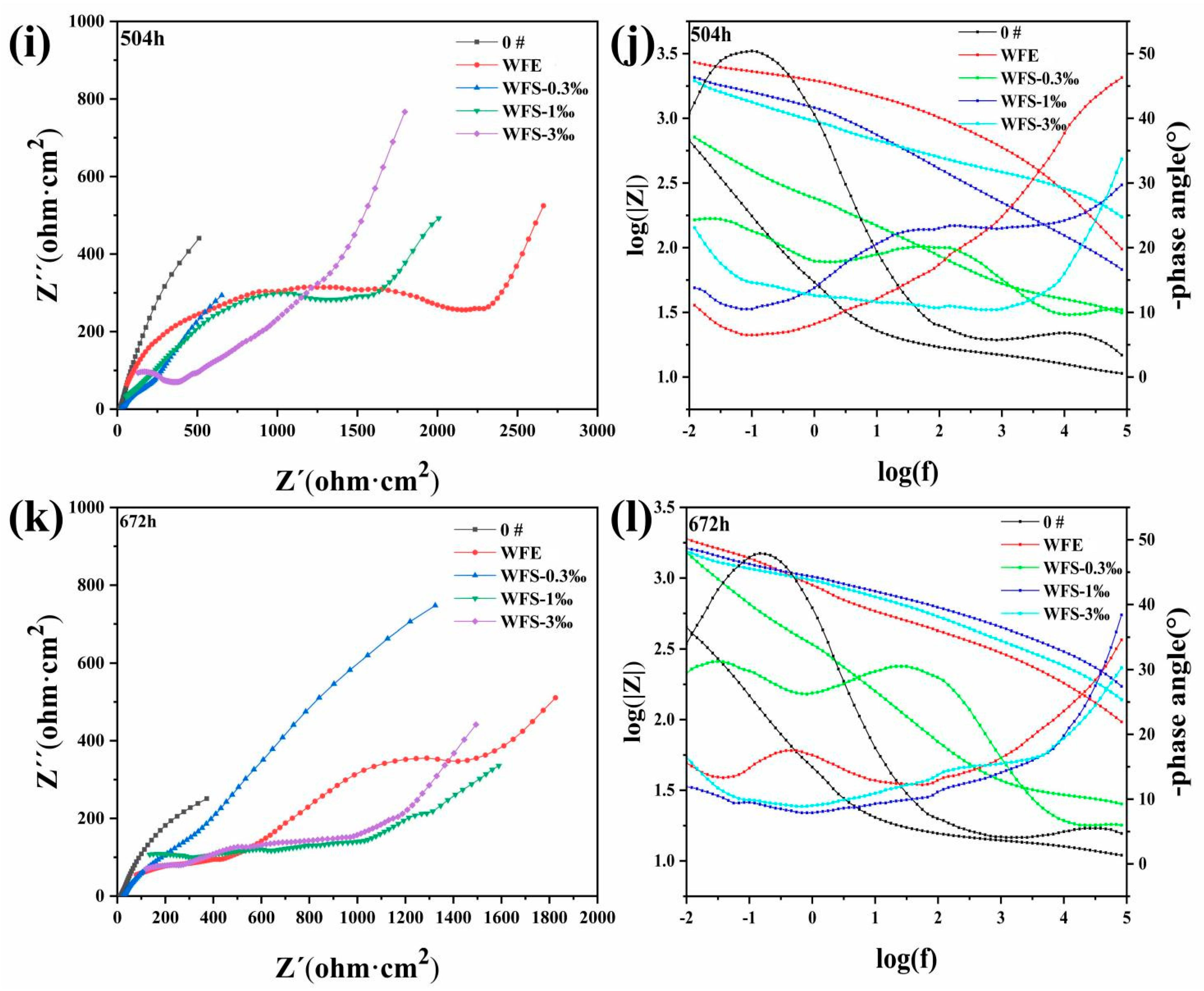
  • Nano-reinforced material was prepared to improve the long-term corrosion resistance of hybrid sealant. The polarization curves show that with the increase of GO@SiO2, the corrosion current density (icorr) and the maintain passive current density (ip) of the sealed samples decrease by an order of magnitude. After immersion for 672 h, the Rct values of samples WFS-1‰ (2104 Ω cm2) and WFS-3‰ (2982 Ω cm2) increased by more than one order of magnitude compared with 0# (131 Ω cm2). Hybrid sealant can effectively slow down the migration process of chloride ions for more than 28 days.

Supplementary Materials

The following supporting information can be downloaded at: https://www.mdpi.com/article/10.3390/coatings15060623/s1, Table S1: EIS fitting data of specimen 0# after soaking for 24~168 h. Table S2. EIS fitting data of specimen 0# after soaking for 336~672 h. Table S3. EIS fitting data of specimen WFE after soaking for 24~48 h. Table S4. EIS fitting data of specimens WFE after soaking for 168~672 h. Table S5. EIS fitting data of specimens WFS-0.3‰ after soaking for different time. Table S6. EIS fitting data of specimens WFS-1‰ after soaking for 24 h. Table S7. EIS fitting data of specimens WFS-1‰ after soaking for 48~168 h. Table S8. EIS fitting data of specimens WFS-1‰ after soaking for 336~672 h. Table S9. EIS fitting data of specimens WFS-3‰ after soaking for 24 h. Table S10. EIS fitting data of specimens WFS-3‰ after soaking for 48~672 h.

Author Contributions

Conceptualization, G.W. and Z.Z.; methodology, G.W.; software, S.Z. and Y.T.; validation, J.S. and Z.Z.; formal analysis, G.W.; investigation, Y.C.; resources, Y.J.; data curation, Y.C.; writing—original draft preparation, G.W.; writing—review and editing, Y.T.; visualization, Y.J.; supervision, S.Z.; project administration, Z.Z.; funding acquisition, G.W. All authors have read and agreed to the published version of the manuscript.

Funding

This research was funded by [Nantong Natural Science Foundation Project] grant number JC2024047.

Institutional Review Board Statement

Not applicable.

Informed Consent Statement

Not applicable.

Data Availability Statement

Where no new data were created, or where data is unavailable due to privacy or ethical restrictions.

Conflicts of Interest

The authors declare no conflict of interest.

References

  1. Li, G.; Gan, Y.; Liu, C.; Shi, Y.; Zhao, Y.; Kou, S. Corrosion and Wear Resistance of Fe-Based Amorphous Coatings. Coatings 2020, 10, 73. [Google Scholar] [CrossRef]
  2. Liu, M.M.; Hu, H.X.; Zheng, Y.G. Effects of three sealing methods of aluminum phosphate sealant on corrosion resistance of the Fe-based amorphous coating. Surf. Coat. Technol. 2017, 309, 579–589. [Google Scholar] [CrossRef]
  3. Wang, M.; Zhou, Z.; Wang, Q.; Wu, L.; Zhang, X. Long term semiconducting and passive film properties of a novel dense FeCrMoCBY amorphous coating by atmospheric plasma spraying. Appl. Surf. Sci. 2019, 495, 143600. [Google Scholar] [CrossRef]
  4. Wang, Y.; Jiang, S.L.; Zheng, Y.G.; Ke, W.; Sun, W.H.; Wang, J.Q. Electrochemical behaviour of Fe-based metallic glasses in acidic and neutral solutions. Corros. Sci. 2012, 63, 159–173. [Google Scholar] [CrossRef]
  5. Zhang, S.D.; Wu, J.; Qi, W.B.; Wang, J.Q. Effect of porosity defects on the long-term corrosion behaviour of Fe-based amorphous alloy coated mild steel. Corros. Sci. 2016, 110, 57–70. [Google Scholar] [CrossRef]
  6. Zhang, J.; Wang, Z.; Lin, P.; Si, L.; Shen, G.; Zhou, Z.; Jiang, S.; Lu, W. Corrosion of plasma sprayed NiCrAl/Al2O3–13 wt-% TiO2 coatings with and without sealing. Surf. Eng. 2012, 28, 345–350. [Google Scholar] [CrossRef]
  7. Shankar, A.R.; Mudali, U.K. Laser surface modification of plasma sprayed yttria stabilised zirconia coatings on type 316L stainless steel. Surf. Eng. 2009, 25, 241–248. [Google Scholar] [CrossRef]
  8. Xie, G.; Lin, X.; Wang, K.; Mo, X.; Zhang, D.; Lin, P. Corrosion characteristics of plasma-sprayed Ni-coated WC coatings comparison with different post-treatment. Corros. Sci. 2007, 49, 662–671. [Google Scholar] [CrossRef]
  9. Parhizkar, N.; Ramezanzadeh, B.; Shahrabi, T. Corrosion protection and adhesion properties of the epoxy coating applied on the steel substrate pre-treated by a sol-gel based silane coating filled with amino and isocyanate silane functionalized graphene oxide nanosheets. Appl. Surf. Sci. 2018, 439, 45–59. [Google Scholar] [CrossRef]
  10. Wang, G.; Zhou, Z.; Zhang, X.; Zhang, K.; Wu, L.; Yang, G. Synthesis of novel waterborne silicone modified acrylic sealant and its corrosion resistance in Fe-based amorphous coatings. Prog. Org. Coat. 2022, 170, 106950. [Google Scholar] [CrossRef]
  11. Dong, Q.; Ba, Z.; Jia, Y.; Chen, Y.; Lv, X.; Zhang, X.; Wang, Z. Effect of solution concentration on sealing treatment of Mg-Al hydrotalcite film on AZ91D Mg alloy. J. Magnes. Alloys 2017, 5, 320–325. [Google Scholar] [CrossRef]
  12. Ivanou, D.K.; Yasakau, K.A.; Kallip, S.; Lisenkov, A.D.; Starykevich, M.; Lamaka, S.V.; Ferreira, M.G.S.; Zheludkevich, M.L. Active corrosion protection coating for a ZE41 magnesium alloy created by combining PEO and sol-gel techniques. RSC Adv. 2016, 6, 12553–12560. [Google Scholar] [CrossRef]
  13. Zhang, J.; Wang, Z.; Lin, P.; Lu, W.; Zhou, Z.; Jiang, S. Effect of Sealing Treatment on Corrosion Resistance of Plasma-Sprayed NiCrAl/Cr2O3-8wt.%TiO2 Coating. J. Therm. Spray Technol. 2011, 20, 508–513. [Google Scholar] [CrossRef]
  14. Zhang, Y.; Wang, Z.; Shi, Y.; Shao, Y.; Gu, C. Combined effect of heat treatment and sealing on the corrosion resistance of reactive plasma sprayed TiNx/TiOy coatings. Ceram. Int. 2019, 45, 24545–24553. [Google Scholar] [CrossRef]
  15. Liu, M.; Wang, Z.; Hu, H.; Zhang, L.; Zheng, Y. Effect of Sealing Treatments on Erosion–Corrosion of a Fe-Based Amorphous Metallic Coating in 3.5 wt.% NaCl Solution with 2 wt.% Sand. Metals 2022, 12, 680. [Google Scholar] [CrossRef]
  16. Arun, S.; Sooraj, P.N.; Hariprasad, S.; Arunnellaiappan, T.; Rameshbabu, N. Fabrication of superhydrophobic coating on PEO treated zirconium samples and its corrosion resistance. Mater. Today Proc. 2020, 27, 2056–2060. [Google Scholar] [CrossRef]
  17. Zhang, J.; Wang, Z.; Lin, P. Effects of sealing on corrosion behaviour of plasma-sprayed Cr2O3–8TiO2 coating. Surf. Eng. 2013, 29, 594–599. [Google Scholar] [CrossRef]
  18. Novoselov, K.S.; Fal, V.I.; Colombo, L.; Gellert, P.R.; Schwab, M.G.; Kim, K. A roadmap for graphene. Nature 2012, 490, 192–200. [Google Scholar] [CrossRef]
  19. Lee, Y.; Ahn, J.H. Graphene-Based Transparent Conductive Films (vol 8, 1330001, 2013). Nano 2015, 10, 1592001. [Google Scholar] [CrossRef]
  20. Li, Y.; Huang, Y.; Wang, F.; Liang, W.; Yang, H.; Wu, D. Fabrication of acrylic acid modified graphene oxide (AGO)/acrylate composites and their synergistic mechanisms of anticorrosion and antifouling properties. Prog. Org. Coat. 2022, 168, 106910. [Google Scholar] [CrossRef]
  21. Zhou, S.; Wu, Y.; Zhao, W.; Yu, J.; Jiang, F.; Ma, L. Comparative corrosion resistance of graphene sheets with different structures in waterborne epoxy coatings. Colloids Surf. A Physicochem. Eng. Asp. 2018, 556, 273–283. [Google Scholar] [CrossRef]
  22. Wang, G.; Zhou, Z.; Hu, Q.; Shi, X.; Zhang, X.; Zhang, K.; Wu, L. Preparation of eco-friendly natural rosin-based SiO2–NH2@GO hybrid sealant and study on corrosion resistance of Fe-based amorphous coating for steel substrate. Carbon 2023, 201, 170–188. [Google Scholar] [CrossRef]
  23. Selim, M.S.; El-Safty, S.A.; Fatthallah, N.A.; Shenashen, M.A. Silicone/graphene oxide sheet-alumina nanorod ternary composite for superhydrophobic antifouling coating. Prog. Org. Coat. 2018, 121, 160–172. [Google Scholar] [CrossRef]
  24. Guo, S.-Y.; Luo, H.-H.; Tan, Z.; Chen, J.-Z.; Zhang, L.; Ren, J. Impermeability and interfacial bonding strength of TiO2-graphene modified epoxy resin coated OPC concrete. Prog. Org. Coat. 2021, 151, 106029. [Google Scholar] [CrossRef]
  25. Othman, N.H.; Yahya, W.Z.N.; Ismail, M.C.; Mustapha, M. Highly dispersed graphene oxide–zinc oxide nanohybrids in epoxy coating with improved water barrier properties and corrosion resistance. J. Coat. Technol. Res. 2020, 17, 101–114. [Google Scholar] [CrossRef]
  26. Guerrero-Bermea, C.; Vazquez-Rodriguez, S.; Sanchez-Valdes, S.; Uribe-Calderon, J.A. Synthesis of montmorillonite/modified graphene oxide filler and its effect on the properties of PP composites. Polym. Bull. 2021, 78, 3443–3457. [Google Scholar] [CrossRef]
  27. Cui, G.; Zhang, C.; Wang, A.; Zhou, X.; Xing, X.; Liu, J.; Li, Z.; Chen, Q.; Lu, Q. Research progress on self-healing polymer/graphene anticorrosion coatings. Prog. Org. Coat. 2021, 155, 106231. [Google Scholar] [CrossRef]
  28. Chen, J.; Shi, X.; Qi, S.; Mohai, M.; Bertóti, I.; Gao, Y.; Dong, H. Reducing and multiple-element doping of graphene oxide using active screen plasma treatments. Carbon 2015, 95, 338–346. [Google Scholar] [CrossRef]
  29. Xu, G.; Deng, C.; Xing, L.; Hu, J. Preparation and properties of siloxane-modified styrene-acrylate latex particles with core-shell structure. Int. J. Polym. Mater. Polym. Biomater. 2013, 62, 488–492. [Google Scholar] [CrossRef]
  30. Lei, H.; He, D.; Guo, Y.; Tang, Y.; Huang, H. Synthesis and characterization of UV-absorbing fluorine-silicone acrylic resin polymer. Appl. Surf. Sci. 2018, 442, 71–77. [Google Scholar] [CrossRef]
  31. Wu, Y.; Wen, S.; Chen, K.; Wang, J.; Wang, G.; Sun, K. Enhanced corrosion resistance of waterborne polyurethane containing sulfonated graphene/zinc phosphate composites. Prog. Org. Coat. 2019, 132, 409–416. [Google Scholar] [CrossRef]
  32. Keshmiri, N.; Najmi, P.; Ramezanzadeh, B.; Ramezanzadeh, M.; Bahlakeh, G. Nano-scale P, Zn-codoped reduced-graphene oxide incorporated epoxy composite; synthesis, electronic-level DFT-D modeling, and anti-corrosion properties. Prog. Org. Coat. 2021, 159, 106416. [Google Scholar] [CrossRef]
  33. Jindal, R.; Raja, V.; Gibson, M.A.; Styles, M.J.; Bastow, T.J.; Hutchinson, C. Effect of annealing below the crystallization temperature on the corrosion behavior of Al–Ni–Y metallic glasses. Corros. Sci. 2014, 84, 54–65. [Google Scholar] [CrossRef]
  34. Kumar, A.; Nayak, S.K.; Sarkar, K.; Banerjee, A.; Mondal, K.; Laha, T. Investigation of nano-and micro-scale structural evolution and resulting corrosion resistance in plasma sprayed Fe-based (Fe-Cr-BCP) amorphous coatings. Surf. Coat. Technol. 2020, 397, 126058. [Google Scholar] [CrossRef]
  35. Mansfeld, F.; Kendig, M. Evaluation of anodized aluminum surfaces with electrochemical impedance spectroscopy. J. Electrochem. Soc. 1988, 135, 828. [Google Scholar] [CrossRef]
  36. Hitzig, J.; Jüttner, K.; Lorenz, W.J.; Paatsch, W. AC-Impedance measurements on corroded porous aluminum oxide films. J. Electrochem. Soc. 1986, 133, 887. [Google Scholar] [CrossRef]
  37. Chung, S.; Cheng, J.; Chiou, S.; Shih, H. EIS behavior of anodized zinc in chloride environments. Corros. Sci. 2000, 42, 1249–1268. [Google Scholar] [CrossRef]
  38. Liu, H.; Gu, T.; Zhang, G.; Cheng, Y.; Wang, H.; Liu, H. The effect of magneticfield on biomineralization and corrosion behavior of carbon steel induced by iron-oxidizing bacteria. Corros. Sci. 2016, 102, 93–102. [Google Scholar] [CrossRef]
  39. Yang, Y.; Zhang, C.; Peng, Y.; Yu, Y.; Liu, L. Effects of crystallization on the corrosion resistance of Fe-based amorphous coatings. Corros. Sci. 2012, 59, 10–19. [Google Scholar]
  40. Liu, C.; Bi, Q.; Leyland, A.; Matthews, A. An electrochemical impedance spectroscopy study of the corrosion behaviour of PVD coated steels in 0.5 N NaCl aqueous solution: Part II.: EIS interpretation of corrosion behaviour. Corros. Sci. 2003, 45, 1257–1273. [Google Scholar]
  41. Guo, R.Q.; Zhang, C.; Chen, Q.; Yang, Y.; Li, N.; Liu, L. Study of structure and corrosion resistance of Fe-based amorphous coatings prepared by HVAF and HVOF. Corros. Sci. 2011, 53, 2351–2356. [Google Scholar] [CrossRef]
  42. Du, F.; Jin, Z.; She, W.; Xiong, C.; Feng, G.; Fan, J. Chloride ions migration and induced reinforcement corrosion in concrete with cracks: A comparative study of current acceleration and natural marine exposure. Constr. Build. Mater. 2020, 263, 120099. [Google Scholar] [CrossRef]
  43. Zhang, C.; Chan, K.C.; Wu, Y.; Liu, L. Pitting initiation in Fe-based amorphous coatings. Acta Mater. 2012, 60, 4152–4159. [Google Scholar] [CrossRef]
  44. Sarac, I.; Adin, H.; Temiz, S. Experimental determination of the static and fatigue strength of the adhesive joints bonded by epoxy adhesive including different particles. Composites 2018, 155B, 92–103. [Google Scholar] [CrossRef]
  45. Wei, H.; Xia, J.; Zhou, W.; Zhou, L.; Ostrikov, K.K. Adhesion and cohesion of epoxy-based industrial composite coatings. Compos. Part B Eng. 2020, 193, 108035. [Google Scholar] [CrossRef]
Figure 1. Schematic diagram of the overall sealing process of Fe-based amorphous coatings. (1) The preparation process of GO@SiO2; (2) the sealing treatment of Fe-based amorphous coating.
Coatings 15 00623 g001
Figure 2. Microstructure characterization of As-sprayed coating and powder. (a) Powder morphology; (b) The crystal structure of coatings and powders; (c) Powder particle size distribution curve.
Coatings 15 00623 g002
Figure 3. The properties of WFE and WFS. (a) Particle size optical image and size histogram; (b) the FTIR spectra of the WFS; (c) thermal analysis of WFS; (d) DSC results of WFS.
Coatings 15 00623 g003
Figure 4. TEM morphology of WFE. (a) Emulsion morphology; (b) Enlarged view of emulsion morphology.
Coatings 15 00623 g004
Figure 5. XPS spectra of GO@SiO2. (a) C1s orbital characteristic peak; (b) Si2p orbital characteristic peak; (c) O1s orbital characteristic peak; (d) N1s orbital characteristic peak.
Coatings 15 00623 g005
Figure 6. Crystal structure (a) and thermogravimetric analysis of nanoparticles (b).
Coatings 15 00623 g006
Figure 7. TEM images of GO@SiO2. (a) The microscopic morphology of nano-SiO2; (b) The microscopic morphology of SiO2-NH2; (c) Microstructure and Dimensions of GO; (d) Structural and morphological characterization of GO@SiO2.
Coatings 15 00623 g007
Figure 8. Top-view SEM images before and after treatment with different hybrid sealants. (a) 0#, (b) WFE, (c) WFS-0.3‰, (d) WFS-1‰, (e) WFS-3‰, (f) roughness of the sealed coating.
Coatings 15 00623 g008
Figure 9. Cross-section SEM-EDX test results of samples treated with different hybrid sealants. (a) WFS-0.3‰; (b) WFS-1‰; (c) WFS-3‰.
Coatings 15 00623 g009
Figure 10. Three-dimensional X-ray scanning diagram of sealed coating and pore distribution analysis before and after sealing treatment. (a) Before sealing treatment; (b) after sealing treatment; (c) porosity distribution curve; (d) porosity before and after sealing treatment; (e) pore distribution curves of different sizes.
Coatings 15 00623 g010
Figure 11. Tafel curves of samples treated with different hybrid sealants immersed in the salt solution at different times. (a) 24 h; (b) 48 h; (c) 168 h; (d) 336 h; (e) 504 h; (f) 672 h.
Coatings 15 00623 g011
Figure 12. Potentiodynamic polarization test results of samples in salt solution at different times. (a) corrosion potential; (b) corrosion current density; (c) protecting efficiency.
Coatings 15 00623 g012
Figure 13. EIS bode plots of samples treated with different hybrid sealants immersed in the salt solution at different times.
Coatings 15 00623 g013aCoatings 15 00623 g013b
Figure 14. Equivalent circuit diagram based on impedance data. (a) Fitting of Sample 0#; (b) Fitting of samples WFE, WFS-1% and WFS-3%; (c) Fitting of Samples WFE, WFS-0.3%; (d) Fitting of Samples WFS-1% and WFS-3%.
Coatings 15 00623 g014
Figure 15. Top view or cross-section SEM-EDX test result of the corrosion morphology of samples treated with different hybrid sealants immersed in the salt solution for 168 h. (a) Unsealed coating; (d) Cross-section of unsealed coating; (b) WFE; (c) WFS-0.3‰; (e) WFS-1‰; (f) WFS-3‰.
Coatings 15 00623 g015
Figure 16. Top view or cross-section SEM-EDX test result of the corrosion morphology of samples treated with different hybrid sealants immersed in the salt solution for 672 h. (a) Unsealed coating(0#); (a’) The cross-sectional morphology of sample 0#; (b) WFE; (b’) The cross-sectional morphology of sample WFE; (c) WFS-0.3‰; (c’) The cross-sectional morphology of sample WFS-0.3‰; (d) WFS-1‰; (d’) The cross-sectional morphology of sample WFS-1‰ (e) WFS-3‰; (e’) The cross-sectional morphology of sample WFS-3‰.
Coatings 15 00623 g016
Table 1. Fe-based amorphous powder composition.
ElementFeCrMoCB
Content (at%)47.623.510.014.24.7
Table 2. Sample abbreviations.
Sample
0#Fe-based amorphous coating (unsealed coating)
WFE (WFS-0)Waterborne acrylic sealant (nanofiller content: 0‰)
WFS-0.3‰Graphene modified waterborne acrylic sealant (nanofiller content: 0.3‰)
WFS-1‰Graphene modified waterborne acrylic sealant (nanofiller content: 1‰)
WFS-3‰Graphene modified waterborne acrylic sealant (nanofiller content: 3‰)
Disclaimer/Publisher’s Note: The statements, opinions and data contained in all publications are solely those of the individual author(s) and contributor(s) and not of MDPI and/or the editor(s). MDPI and/or the editor(s) disclaim responsibility for any injury to people or property resulting from any ideas, methods, instructions or products referred to in the content.

