
Optimization of Elliptical Double-Beta Spray Gun Model Under the Control of Fan Air Pressure


Abstract
1. Introduction
2. Construction of Spot Spraying Experimental Platform
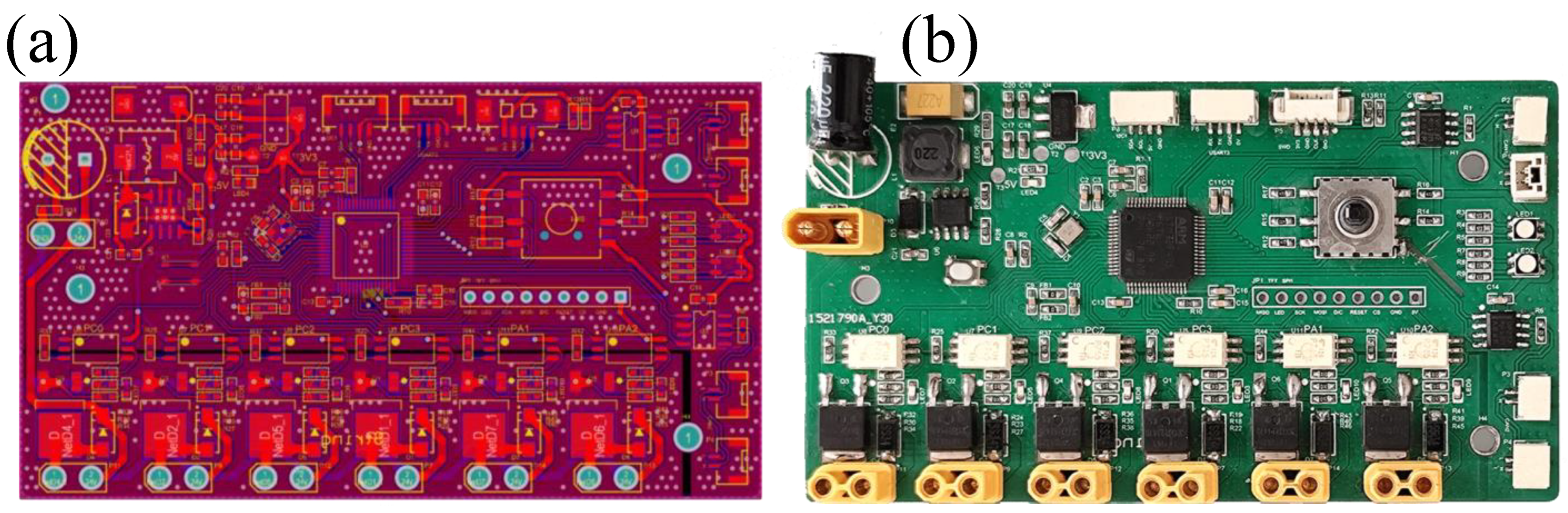
2.1. Equipment Selection
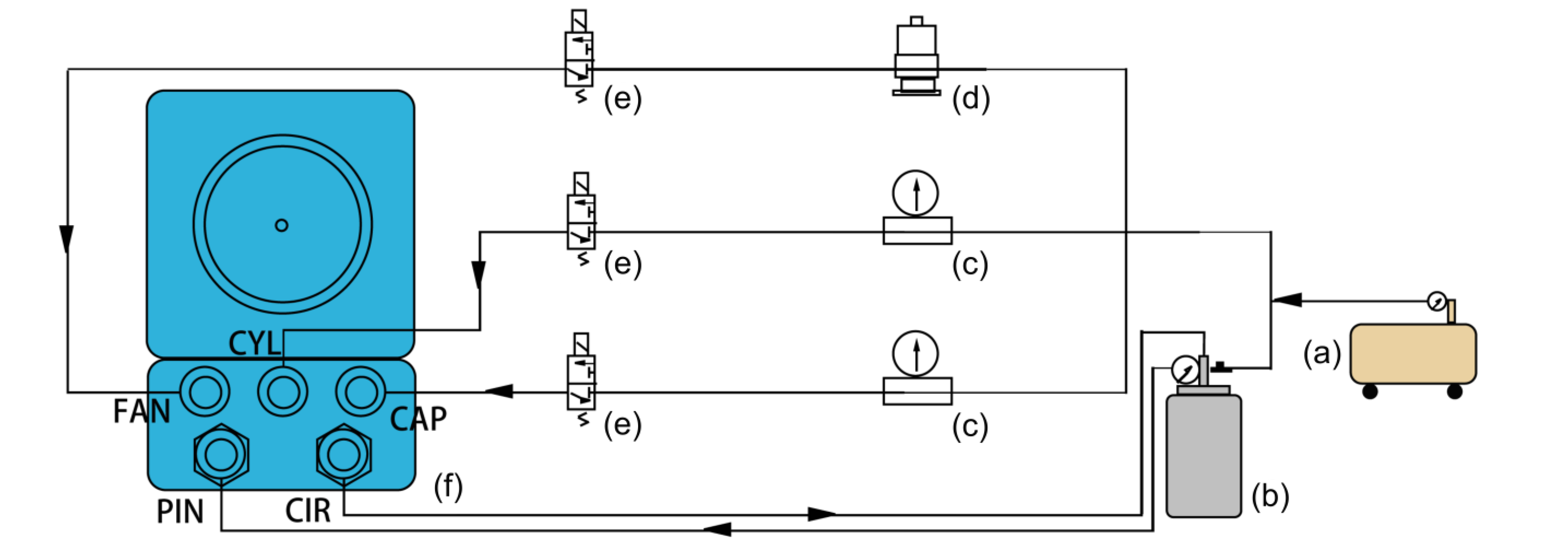
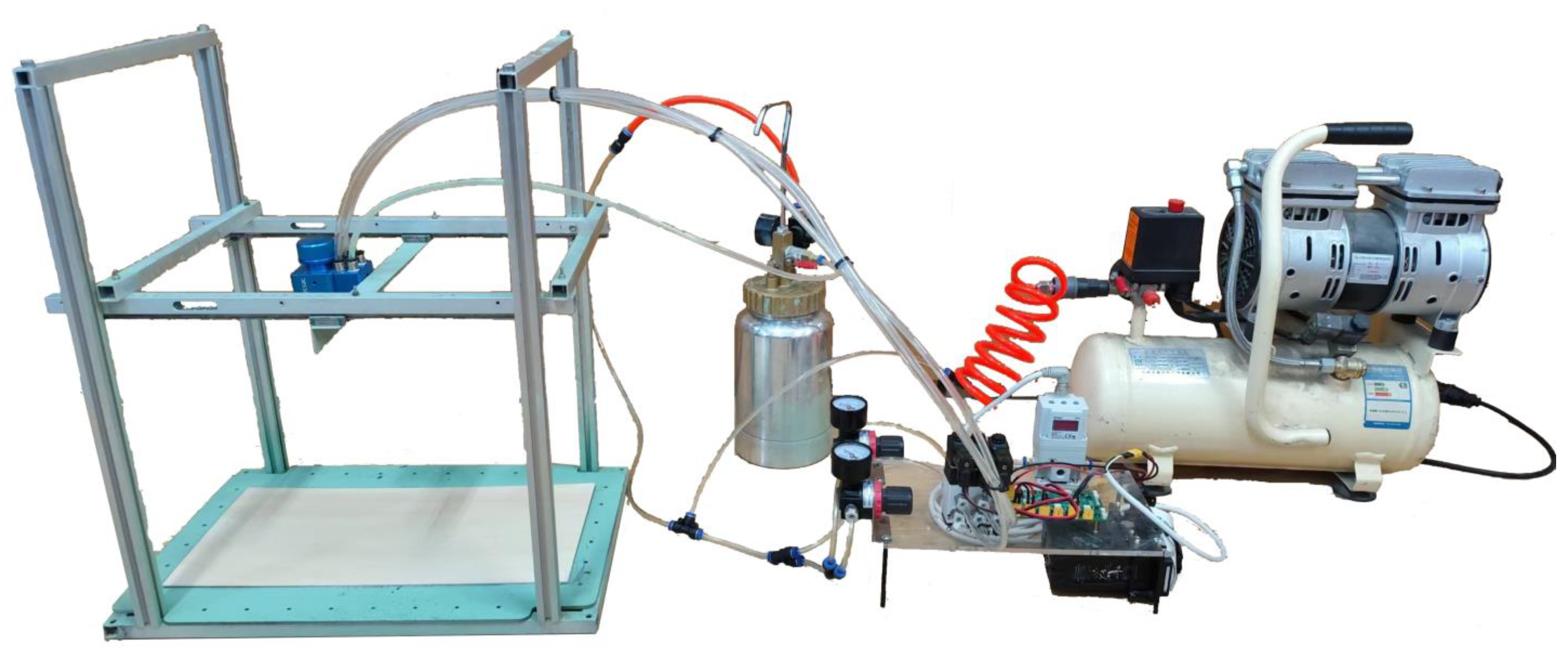
2.2. Configuration and Installation
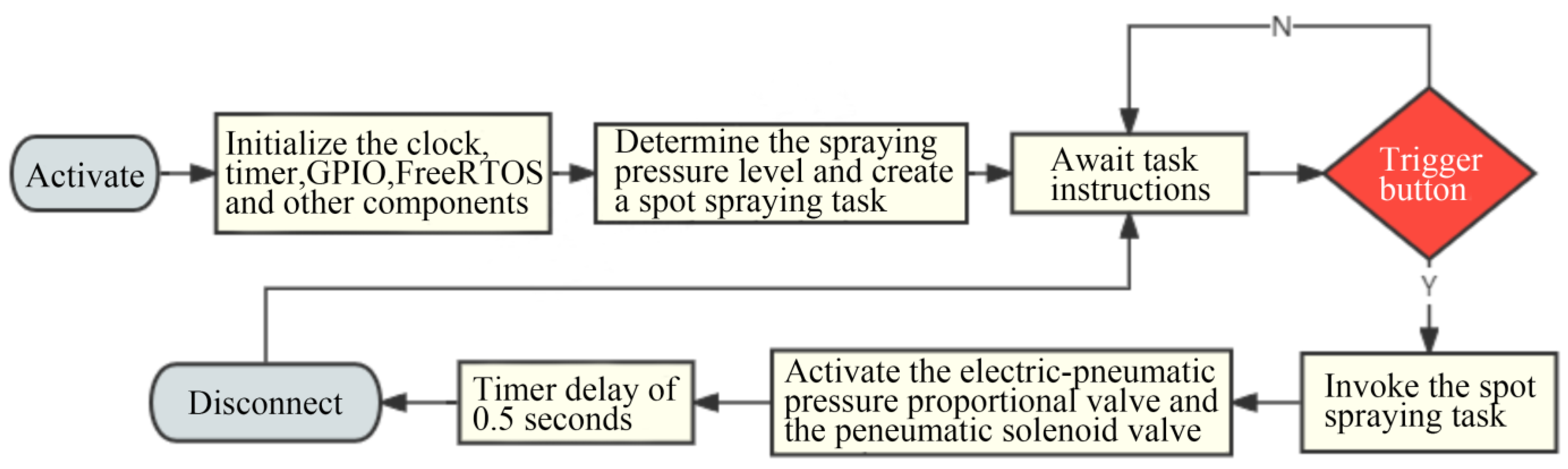
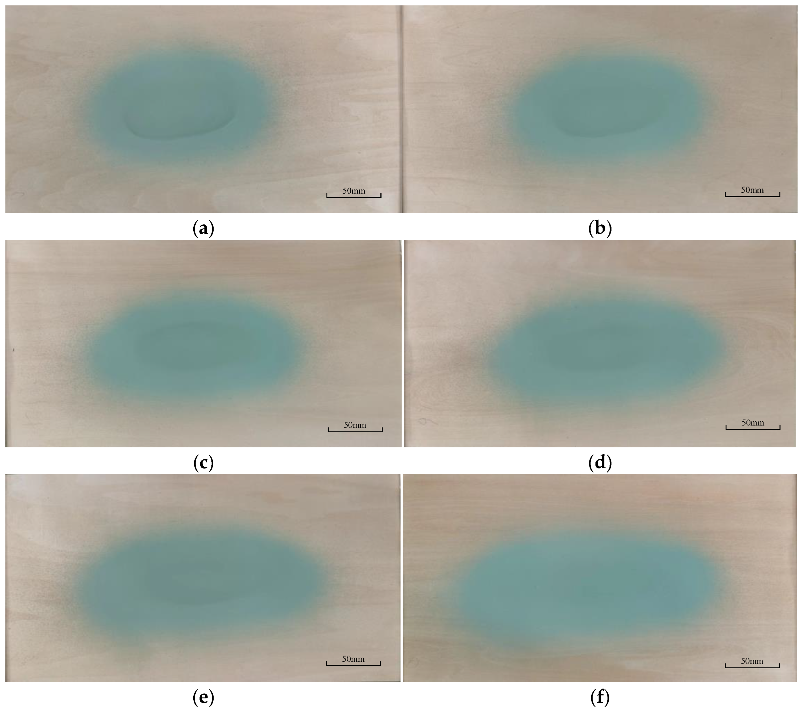
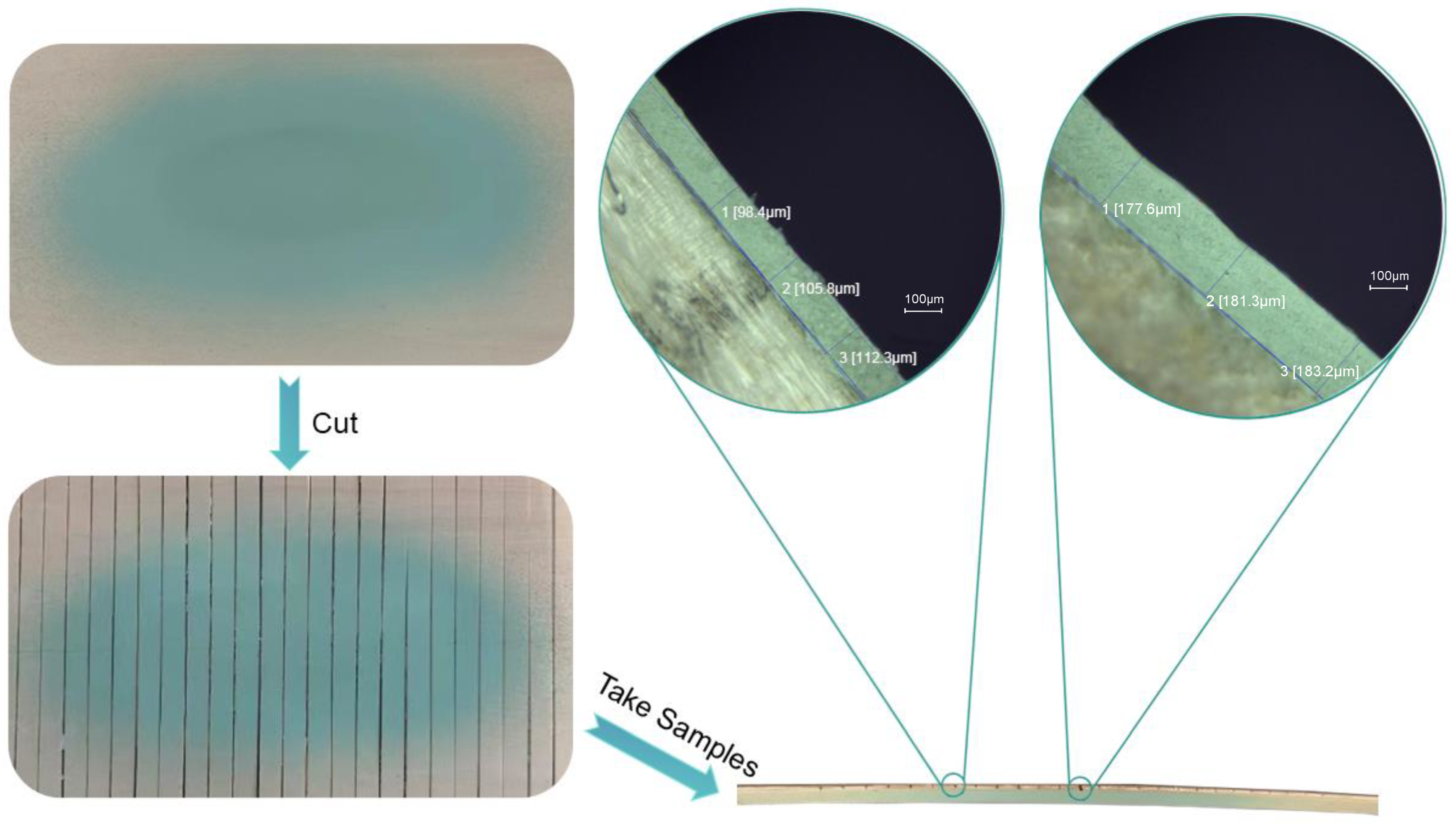
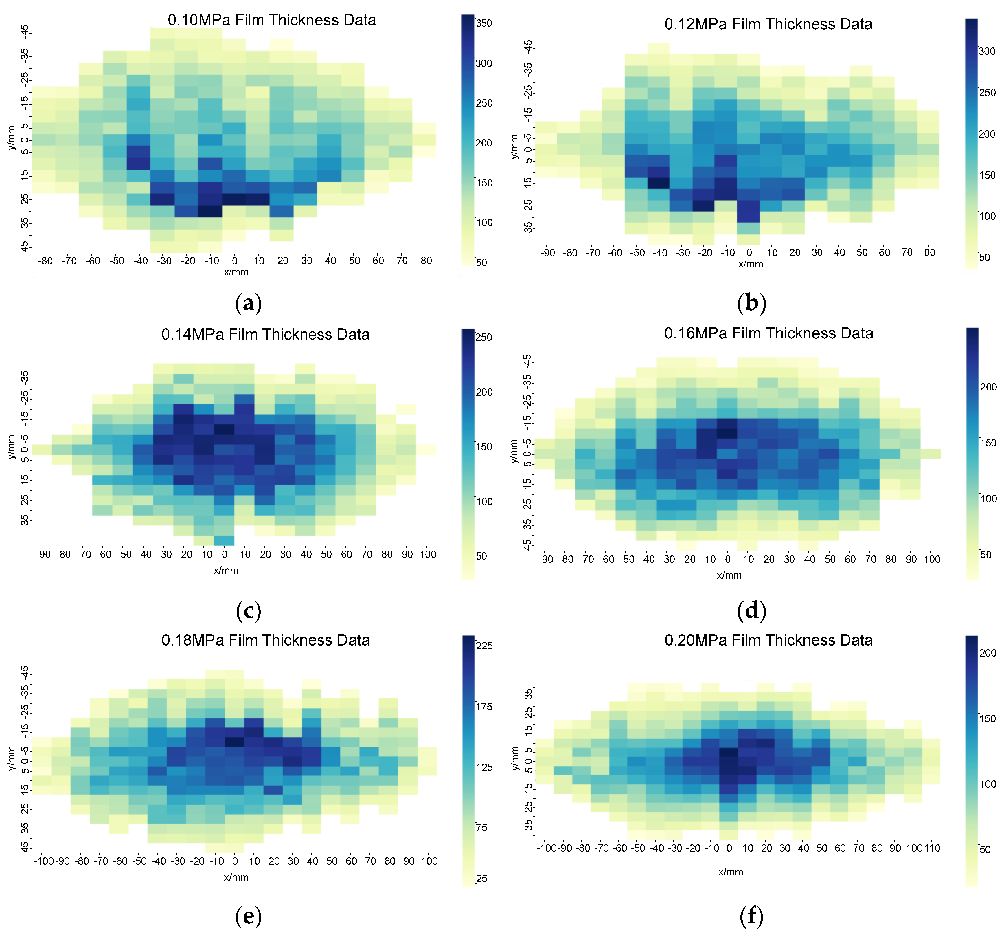
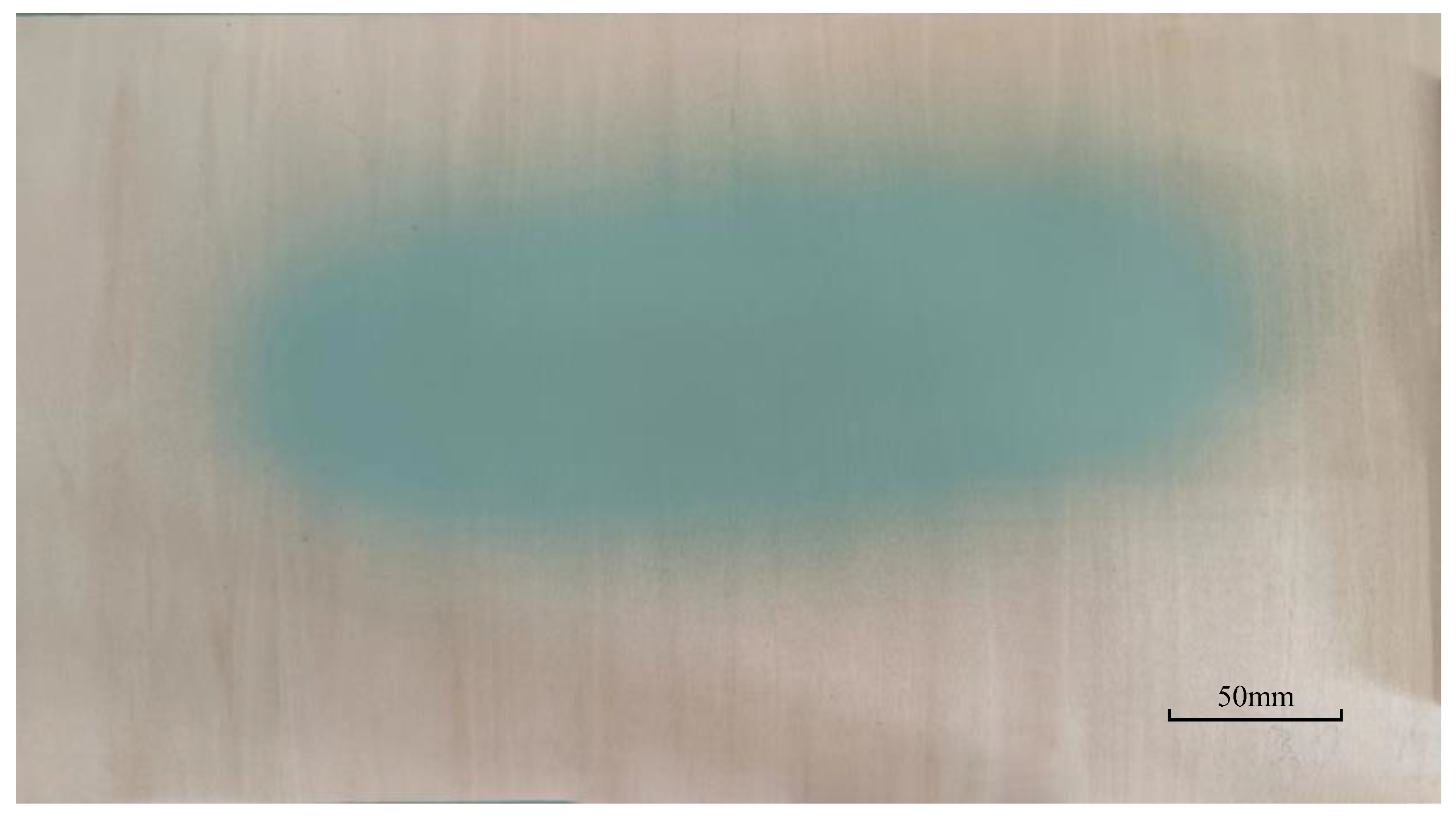
3. Point Spraying
4. Elliptical Double-β Spray Gun Model Optimization
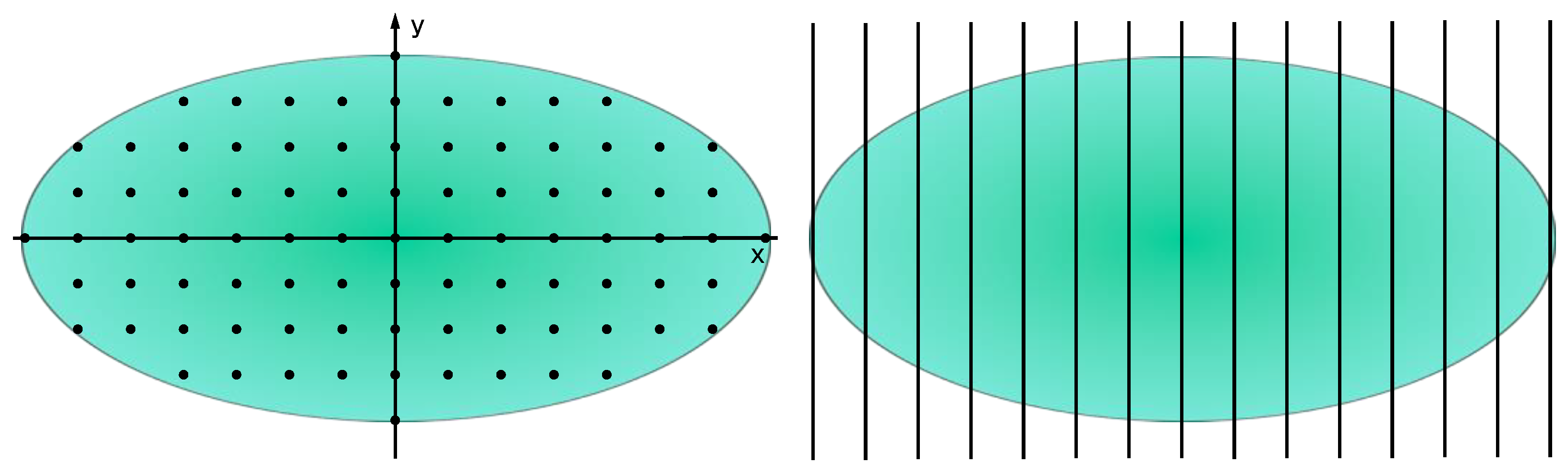
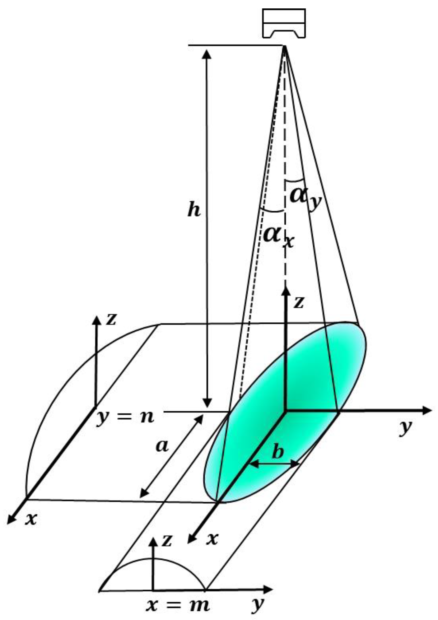
4.1. Elliptical Double-β Spray Gun Model
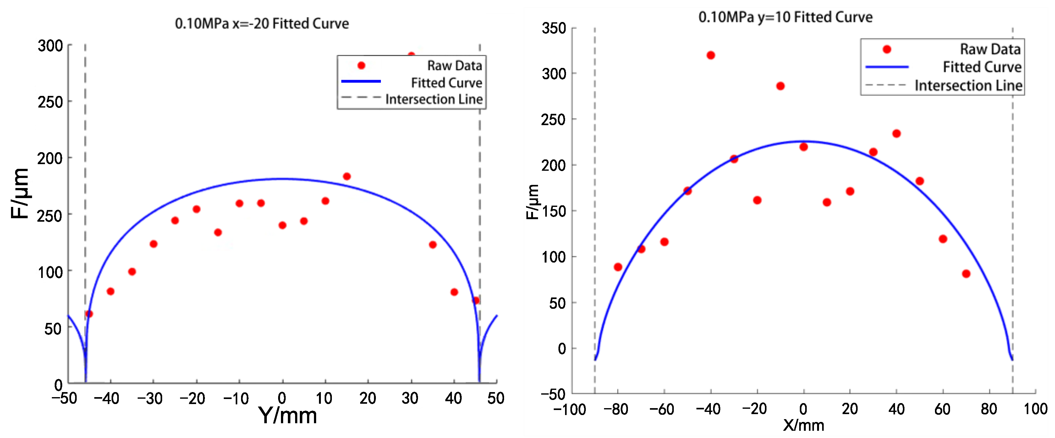
4.2. Parameter Estimation
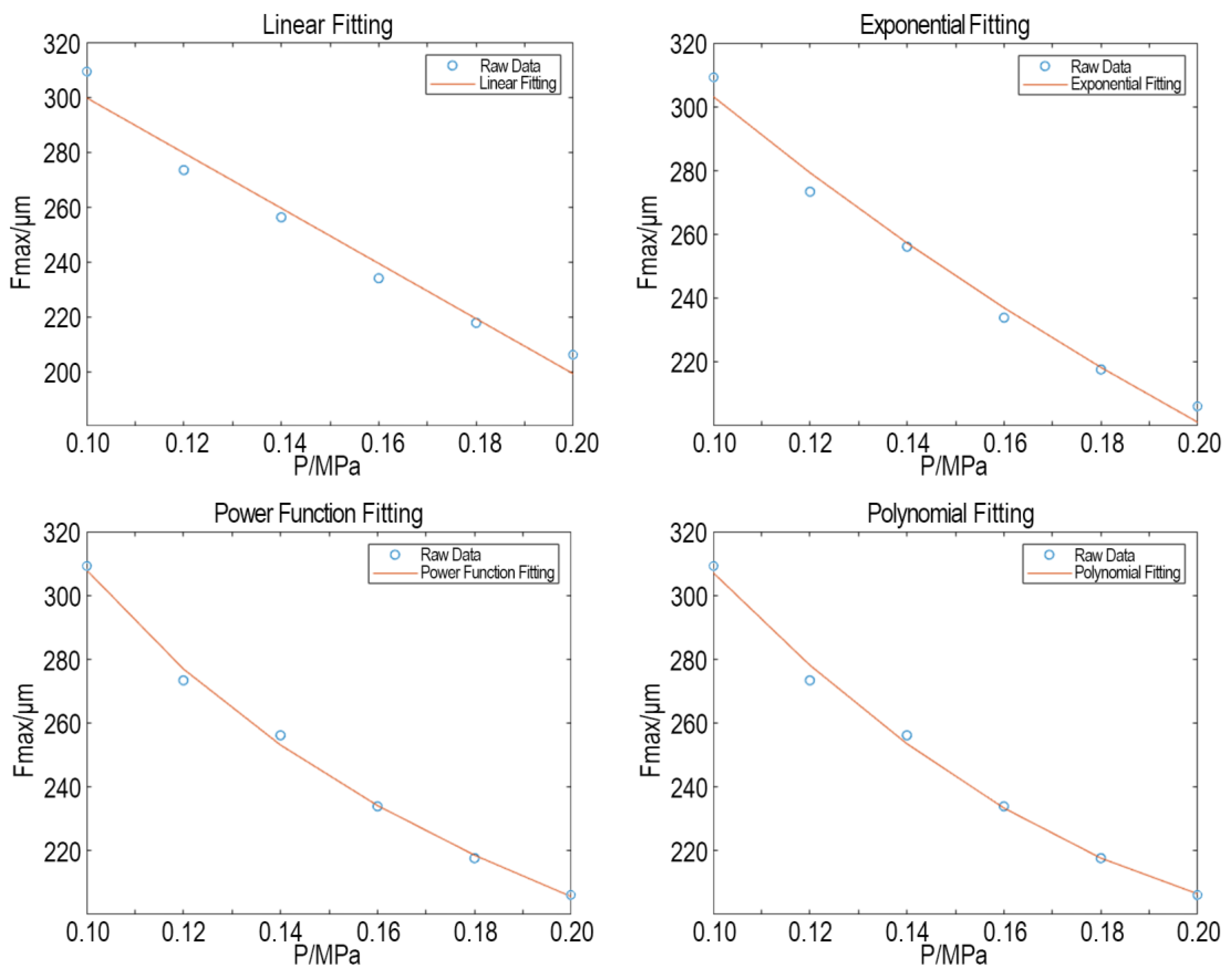
4.3. Model Optimization
5. Spray Gun Model Validation
6. Conclusions
Author Contributions
Funding
Institutional Review Board Statement
Informed Consent Statement
Data Availability Statement
Conflicts of Interest
References
- Jimeno-Morenilla, A.; Azariadis, P.; Molina-Carmona, R.; Kyratzi, S.; Moulianitis, V. Technology enablers for the implementation of Industry 4.0 to traditional manufacturing sectors: A review. Comput. Ind. 2021, 125, 103390. [Google Scholar] [CrossRef]
- Molinaro, M.; Orzes, G. From forest to finished products: The contribution of Industry 4.0 technologies to the wood sector. Comput. Ind. 2022, 138, 103637. [Google Scholar] [CrossRef]
- Chen, Y.C.; Lin, C.H.; Lung, S.C.C.; Chen, K.F.; Wang, W.C.V.; Chou, C.T.; Lai, C.H. Environmental concentration of spray paint particulate matters causes pulmonary dysfunction in human normal bronchial epithelial BEAS-2B cell. Process Saf. Environ. Prot. 2019, 126, 250–258. [Google Scholar] [CrossRef]
- Zeng, M. Factors influencing Utilization efficiency of Coatings and Improvement Measures. Paint. Coat. Ind. 2005, 35, 54. [Google Scholar]
- Brunello, A.; Fabris, G.; Gasparetto, A.; Montanari, A.; Saccomanno, N.; Scalera, L. A survey on recent trends in robotics and artificial intelligence in the furniture industry. Robot. Comput.-Integr. Manuf. 2025, 93, 102920. [Google Scholar] [CrossRef]
- Vidyapati, K.; Kanak, K.; Prasenjit, C.; Kazimieras, Z.E.; Shankar, C. A SWARA-CoCoSo-Based Approach for Spray Painting Robot Selection. Informatica 2022, 33, 35–54. [Google Scholar]
- Jiang, C.; Li, X.; He, W.; Kou, C. Research on Teaching Programming Method for Artificial Spraying Trajectory Based on Binocular Vision. Mach. Des. Manuf. 2022, 4, 33–36. [Google Scholar]
- Ling, L.; Zhang, X.; Hu, X.; Fu, Y.; Yang, D.; Liang, E.; Chen, Y. Research on Spraying Quality Prediction Algorithm for Automated Robot Spraying Based on KHPO-ELM Neural Network. Machines 2024, 12, 100. [Google Scholar] [CrossRef]
- Ning, F.; Shi, Y.; Cai, M.; Wang, Y.; Xu, W. Research Progress of Related Technologies of Electric-Pneumatic Pressure Proportional Valves. Appl. Sci. 2017, 7, 1074. [Google Scholar] [CrossRef]
- Zhang, C.; Shao, W.; Hao, Y. A bionic bird jumping grasping structure design based on stm32 development board control. Sci. Rep. 2024, 14, 10435. [Google Scholar] [CrossRef]
- Zhou, W.; Li, M.; Qiu, M.; Zhang, X.; Liu, J.; Zhang, H. Vehicle body panel thickness optimization by agenetic algorithm. J. Tsinghua Univ. Sci. Technol. 2022, 62, 523–532. [Google Scholar]
- Han, Z.; Ma, S.; Lu, P. Research progress in surface treatment methods for connecting aluminum alloys and composite materials. China Plast. 2024, 38, 124–133. [Google Scholar]
- Yuan, Y.; Liu, G.; Chen, D. Digital Controller for Pneumatic Proportional Directional Valve Based on STM32 Microcontroller. Instrum. Tech. Sens. 2013, 4, 22. [Google Scholar]
- Chen, R.; Zeng, Q.; Yang, J.; Xiong, D.; Li, S.; Su, L. AGV Development Based on FreeRTOS Embedded System. Mach. Des. Res. 2022, 38, 35–41. [Google Scholar]
- Leksycki, K.; Królczyk, J.B. Comparative assessment of the surface topography for different optical profilometry techniques after dry turning of Ti6Al4V titanium alloy. Measurement 2021, 169, 108378. [Google Scholar] [CrossRef]
- GB/T 13452. 2-2008; Paints and Varnishes—Determination of Film Thickness. Standardization Administration of the People’s Republic of China: Beijing, China, 2008; p. 32. [Google Scholar]
- Heras-Domingo, J.; Garay-Ruiz, D. Pythonic Chemistry: The Beginner’s Guide to Digital Chemistry. J. Chem. Educ. 2024, 101, 4883–4891. [Google Scholar] [CrossRef]
- Zhang, Y.; Huang, Y.; Gao, F.; Wang, W. New Model for Air Spray Gun of Robotic Spray-Painting. Chin. J. Mech. Eng. 2006, 42, 226–233. [Google Scholar] [CrossRef]
- Wan, Y.P.; Jia, J. Nonlinear dynamics of asphalt-screed interaction during compaction: Application to improving paving density. Constr. Build. Mater. 2019, 202, 363–373. [Google Scholar] [CrossRef]
- Zhang, Y. Research on Several Key Technologies of Painting Robots. Doctorate Thesis, Xi’an University of Technology, Xi’an, Beijing, 2008. [Google Scholar]
- Piepho, H.P. An adjusted coefficient of determination(R2) for generalized linear mixed models in one go. Biom. J. 2023, 65, 2200290. [Google Scholar] [CrossRef]
- Carvalho, G.; Mykolyshyn, S.; Cabral, B.; Bernardino, J.; Pereira, V. Comparative Analysis of Data Modeling Design Tools. IEEE Access 2022, 10, 3351–3365. [Google Scholar] [CrossRef]
- Peng, Y.; Niu, J.; Huo, P. The Nonlinearity Model Parameter Fitting with MATLAB. Chemistry 2007, 70, 880–883. [Google Scholar]
- Chen, L.; Su, H. Prediction of Gas Emission Based on a Regression Model Using the Polyfit Function. Coal 2014, 23, 7–8+11. [Google Scholar]
- Gu, Q.; Wang, J.; Tong, Y.; Xu, Y. Soil Water Characteristic Curve Test and Simulation of Unsaturated Loess Based on Filter Paper Method. Chin. J. Soil Sci. 2016, 47, 588–593. [Google Scholar]
- Fan, D.C.; Zhu, W.G.; Chen, Y.S.; Xue, K.; Liu, T.X.; Cui, P.Z.; Qi, J.G.; Zhu, Z.Y.; Wang, Y.L. Deep learning model based on Bayesian optimization for predicting the infinite dilution activity coefficients of ionic liquid-solute systems. Eng. Appl. Artif. Intell. 2023, 126, 107127. [Google Scholar] [CrossRef]
- Kim, C.H.; Kim, Y.C. Application of Artificial Neural Network Over Nickel-Based Catalyst for Combined Steam-Carbon Dioxide of Methane Reforming (CSDRM). J. Nanosci. Nanotechnol. 2020, 20, 5716–5719. [Google Scholar] [CrossRef] [PubMed]
- Wang, H. Interpretation of the Standard “Specification for Acceptance of Customized Furniture Installation”. China Wood-Based Panels 2023, 30, 30–33. [Google Scholar]

| Fmax/μm | a/mm | b/mm | |||
|---|---|---|---|---|---|
| x = −20 mm | [178.27, 181.44] | / | [44.06, 48.51] | / | [1.1924, 1.2072] |
| y = 10 mm | [224.83, 227.72] | [89.21, 92.73] | / | [1.8742, 1.9005] | / |
| P/MPa | Fmax/μm | a/mm | b/mm | R2 | ||
|---|---|---|---|---|---|---|
| 0.10 | 309.18 | 93.41 | 46.15 | 1.8887 | 1.2018 | 0.98831 |
| 0.12 | 273.36 | 101.13 | 47.99 | 1.9586 | 1.1955 | 0.99274 |
| 0.14 | 256.17 | 112.73 | 51.46 | 2.0119 | 1.1803 | 0.98944 |
| 0.16 | 233.95 | 120.23 | 53.93 | 2.1263 | 1.1747 | 0.97920 |
| 0.18 | 217.71 | 129.19 | 55.77 | 2.3347 | 1.1675 | 0.98601 |
| 0.20 | 206.09 | 136.72 | 58.25 | 2.5610 | 1.1598 | 0.98395 |
| Linear | Exponential | Power | Polynomial | |
|---|---|---|---|---|
| R2 | 0.96995 | 0.98539 | 0.99664 | 0.99533 |
| RMSE | 6.0514 | 4.2201 | 2.024 | 2.3869 |
| Fmax/μm | a/mm | b/mm | |||
|---|---|---|---|---|---|
| x = 10 mm | [145.66, 150.73] | / | [60.72, 67.88] | / | [1.1286, 1.1507] |
| y = −10 mm | [128.29, 134.06] | [166.29, 175.73] | / | [4.4398, 4.4532] | / |
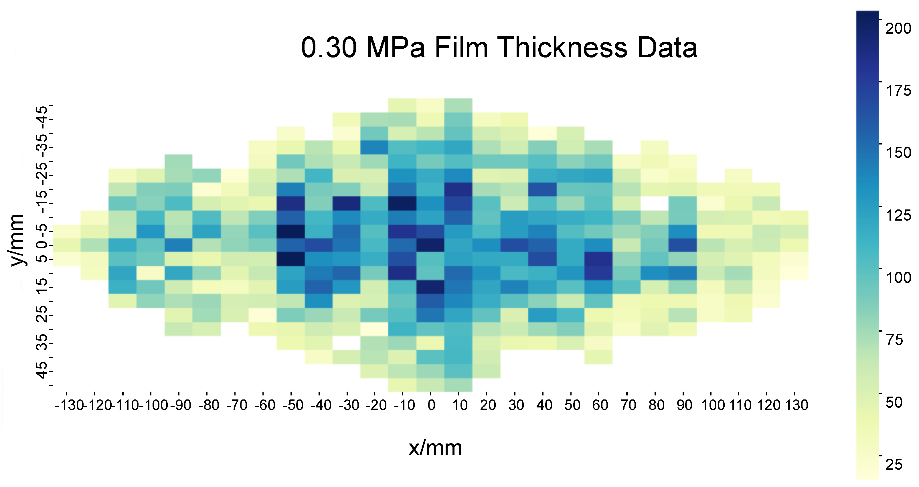
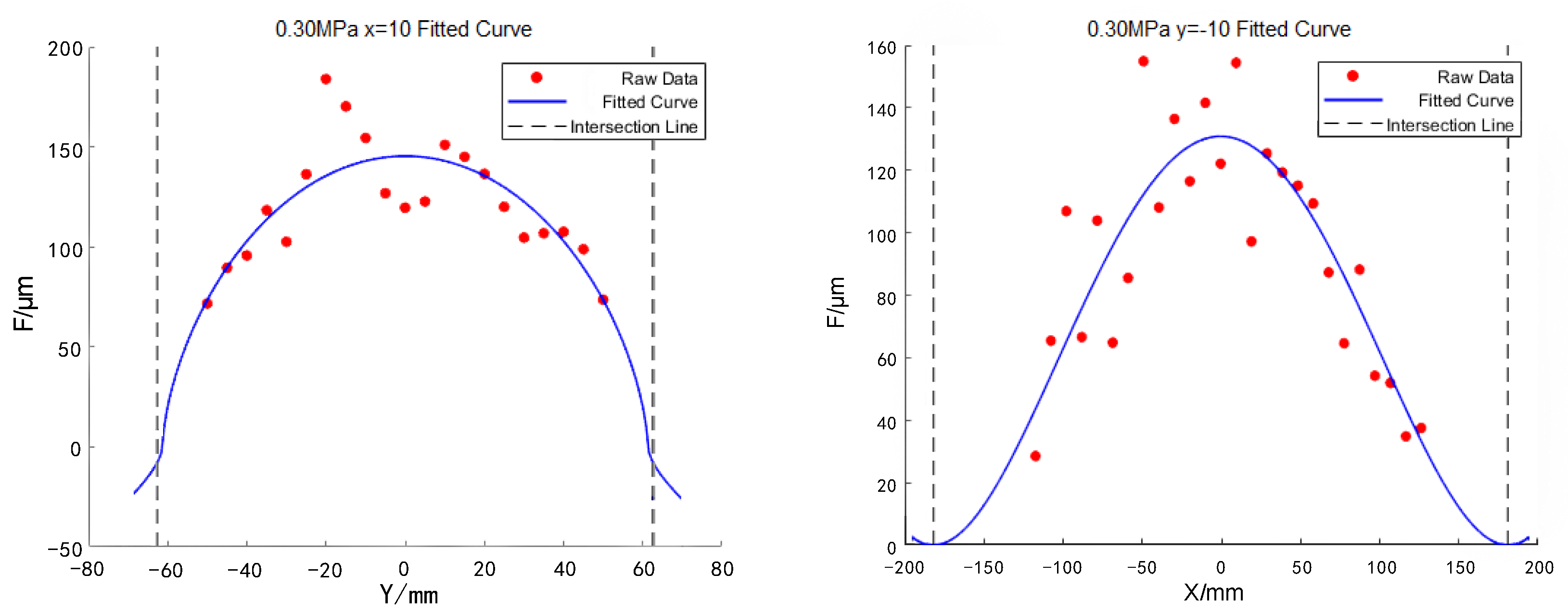
| Fmax/μm | a/mm | b/mm | |||
|---|---|---|---|---|---|
| Predicted | 162.36 | 170.59 | 62.56 | 4.4691 | 1.1395 |
| Fitted | 158.39 | 167.73 | 65.16 | 4.4498 | 1.1447 |
Disclaimer/Publisher’s Note: The statements, opinions and data contained in all publications are solely those of the individual author(s) and contributor(s) and not of MDPI and/or the editor(s). MDPI and/or the editor(s) disclaim responsibility for any injury to people or property resulting from any ideas, methods, instructions or products referred to in the content. |
© 2025 by the authors. Licensee MDPI, Basel, Switzerland. This article is an open access article distributed under the terms and conditions of the Creative Commons Attribution (CC BY) license (https://creativecommons.org/licenses/by/4.0/).
Share and Cite
Tan, Y.; Wang, Z.; Zhang, Z.; Mo, S. Optimization of Elliptical Double-Beta Spray Gun Model Under the Control of Fan Air Pressure. Coatings 2025, 15, 581. https://doi.org/10.3390/coatings15050581
Tan Y, Wang Z, Zhang Z, Mo S. Optimization of Elliptical Double-Beta Spray Gun Model Under the Control of Fan Air Pressure. Coatings. 2025; 15(5):581. https://doi.org/10.3390/coatings15050581
Chicago/Turabian StyleTan, Yajie, Zhuo Wang, Zichao Zhang, and Sundong Mo. 2025. "Optimization of Elliptical Double-Beta Spray Gun Model Under the Control of Fan Air Pressure" Coatings 15, no. 5: 581. https://doi.org/10.3390/coatings15050581
APA StyleTan, Y., Wang, Z., Zhang, Z., & Mo, S. (2025). Optimization of Elliptical Double-Beta Spray Gun Model Under the Control of Fan Air Pressure. Coatings, 15(5), 581. https://doi.org/10.3390/coatings15050581