Article

A Preparation Method for Improving the Thermal Conductivity of Graphene Film

1
Beijing Institute of Metrology, Beijing 100029, China
2
National Institute of Metrology, Beijing 100029, China
*
Author to whom correspondence should be addressed.
Coatings 2025, 15(5), 560; https://doi.org/10.3390/coatings15050560
Submission received: 1 April 2025 / Revised: 17 April 2025 / Accepted: 21 April 2025 / Published: 8 May 2025
(This article belongs to the Special Issue Electrochemical Properties and Applications of Thin Films)

Abstract

:
Graphene films are widely used in thermal management of electronic devices due to their excellent properties such as high flexibility, high thermal conductivity and light weight. However, in the traditional preparation process, some structural defects are introduced, which will lead to an increase in phonon scattering, thereby reducing the thermal conductivity of graphene. Therefore, a new method for preparing graphene thin films is proposed by using the evaporation method; the graphene oxide composite film is prepared by adding carbon-rich molecules (CRMs) to the graphene oxide dispersion liquid. The experimental results show that the addition of a mass fraction of 0.15% CRMs helps to form continuous strips and channels, which are beneficial to the construction of the internal aromatic structure of graphene and improve the crystallinity of graphene film. The in-plane thermal conductivity of the composite film increased from 598.74 W/(m·K) to 704.27 W/(m·K) after adding carbon-rich molecules. However, excess CRMs can lead to the formation of disordered structures during graphitization, which will reduce the thermal conductivity of the film to a certain extent. The radiation properties of graphene films are also proposed to verify the validity of the above conclusions, and the results show that the graphene film with a mass fraction of 0.24% CRMs has better heat dissipation performance, which can be reduced by 5 °C compared with that of pure graphene film. Through the application of graphene in new energy car seats, it is proved that compared with the resistance wire seats, graphene seats have better performance in terms of a fast heating speed and uniform heating.

1. Introduction

With the rapid development and high integration of microelectronic devices, efficient heat dissipation has become an important task in the research into them [1,2]. Due to the shortcomings of brittleness, high porosity and low thermal conductivity, many thermal conductive materials cannot transmit too much heat from microelectronic devices, such as silica gel, pure copper, ceramics and metal matrix composite materials [3,4,5]. Graphene, with its unique six-membered ring structure, has become the most promising thermal conductivity material, with excellent properties such as a high Young’s modulus (1 TPa), high flexibility, high chemical stability and high planar thermal conductivity (3000–5000 W/(m·K) [6,7]. Therefore, graphene is one of the most promising candidate thermal conductivity materials, and has great application potential in high-power devices, heat sinks and wire rods [8,9,10]. Despite the monolayer graphene showing excellent thermal conductivity, which can reach 5300 W/(m·K), it cannot, however, be directly applied in the product and needs to be prepared into composite materials. Problems such as pores and material buildup occur during the preparation process, which will reduce the thermal conductivity of graphene. Therefore, researchers attempted to solve the above problems through various methods. Seol et al. [11] placed a single layer of graphene in a porous cavity on the silica substrate; the thermal conductivity of graphene is measured to be about 600 W/(m·K) at room temperature. Shen et al. [12] prepared large-size films by the self-assembly of graphene oxide (GO), and obtained graphene film after graphitization, with a thermal conductivity of 1100 W/(m·K). Kumar et al. [13] separated GO sheets into large and small layers by centrifugation, then pumped and filtered them into films, respectively, and it was found that large-sized graphene could effectively improve the thermal conductivity of the films. The thermal conductivity of the large-sized graphene film was found to be up to 1390 W/(m·K) by using a laser flashmeter. In the preparation process of graphene oxide by Hummers’ method, due to the introduction of oxygen-containing functional groups in the preparation process, it is possible to form graphene films through the self-assembly process of graphene sheets [14]. However, the process simultaneously introduces graphene lamellar structural defects (in-layer topological defects and nanopores), which greatly damages the rigid lattice structure of graphene and reduces various inherent properties of graphene, including thermal conductivity [15]. In addition, oxygen-containing groups can be treated as zero-dimensional defects and lead to phonon scattering, which affects the heat transport properties of graphene [16]. Many molecular modeling studies have also shown that vacancies, topological defects and adsorptive atoms (such as hydrogen and various ligands) in graphene reduce their thermal conductivity through conduction channels [17]. Haskins et al. [18] observed that all forms of defects would lead to a serious reduction in the thermal conductivity of graphene. Zhang et al. [19] found that vacancy defects of about 8% in graphene would result in extremely low thermal conductivity (about 3 W/(m·K)). In addition, even after GO is fully reduced, typical defects such as five-membered/seven-membered rings, and single-vacancy and suspended C-chains still exist [20,21]. These defects will lead to an increase in phonon scattering, thereby reducing the thermal conductivity of graphene because the inherent defects in the structure of graphene seriously affect its physical and chemical properties, which can be improved by repairing the structural defects in a certain way. Zhu et al. [22] found that the highest Hall mobility could be obtained at 800 °C by using methane and hydrogen plasma to repair and reduce the defects in GO. Li et al. [23] prepared graphene composite films in organic solvents, and this method improved the thermal conductivity of the films by connecting polyimide GO sheets. Although researchers have made some progress in improving the thermal conductivity of graphene films, the current research work mainly focuses on the preparation method of graphene and the post-treatment process of the film, resulting in a high preparation cost of graphene films and difficulties in mass production, although these methods have improved the performance of graphene to a certain extent through defect repair. However, there are some problems such as harsh experimental conditions, inconvenient operation and environmental pollution. Carbon-rich molecules (CRMs) have been proven to have excellent optical properties, such as good water solubility, adsorption, low toxicity, environmental friendliness and good film formation, and have been used in the field of fluorescent anti-counterfeiting materials and metal protection [24,25]. Previous researchers have shown that functional groups on the surface of carbon-rich molecules can interact with defect sites in graphene films to form stable compounds that can repair defects [26,27]. Therefore, this study intends to use carbon-rich molecules to prepare graphene films in order to improve the defects of graphene films and reduce environmental pollution.
In this study, a new method for preparing graphene films is proposed. GO composite films are prepared by the evaporation self-assembly method with GO dispersion liquid as the main body, and other carbon-rich molecules (CRMs) are added. After carbonization, graphitization and rolling treatment, graphene films with high thermal conductivity are obtained. This method can repair the large structural defects in graphene, improve the integrity of conjugated structures in graphene and then improve the thermal conductivity of the film. This method not only has strong operability but also avoids the use of toxic organic solvents, and is safer and more environmentally friendly, so it has greater promotion and application value.

2. Experiment

2.1. Experimental Material

Graphite, sodium nitrate, potassium permanganate (KMnO4), concentrated sulfuric acid (H2SO4, the mass score is 98%), deionized water, hydrogen peroxide (H2O2, the volume fraction is 30%), citric acid (C6H8O7), urea and ultrapure water were purchased from Beijing Graphene Technology Research Institute (Beijing, China).

2.2. Preparation of Carbon-Rich Molecules

Carbon-rich molecules (CRMs) were prepared by the method of preparing fluorescent carbon quantum dots in a citric acid–urea system. Use a balance to take 0.96 g citric acid and 0.3 g urea, pour them into a 50 mL beaker, then add 20 mL ultrapure water and stir to dissolve them fully. The prepared solution is poured into a hydrothermal reactor containing Teflon, and reacted in a sand bath at 180 °C for 2 h. After the reaction is over, the reaction system is naturally cooled to room temperature. The cooling liquid is filtered by a 0.22 μm water filter membrane under vacuum, and finally, a light-yellow carbon quantum dot solution is obtained; the carbon-rich molecules with a concentration of 1.2 mg/mL are finally prepared.

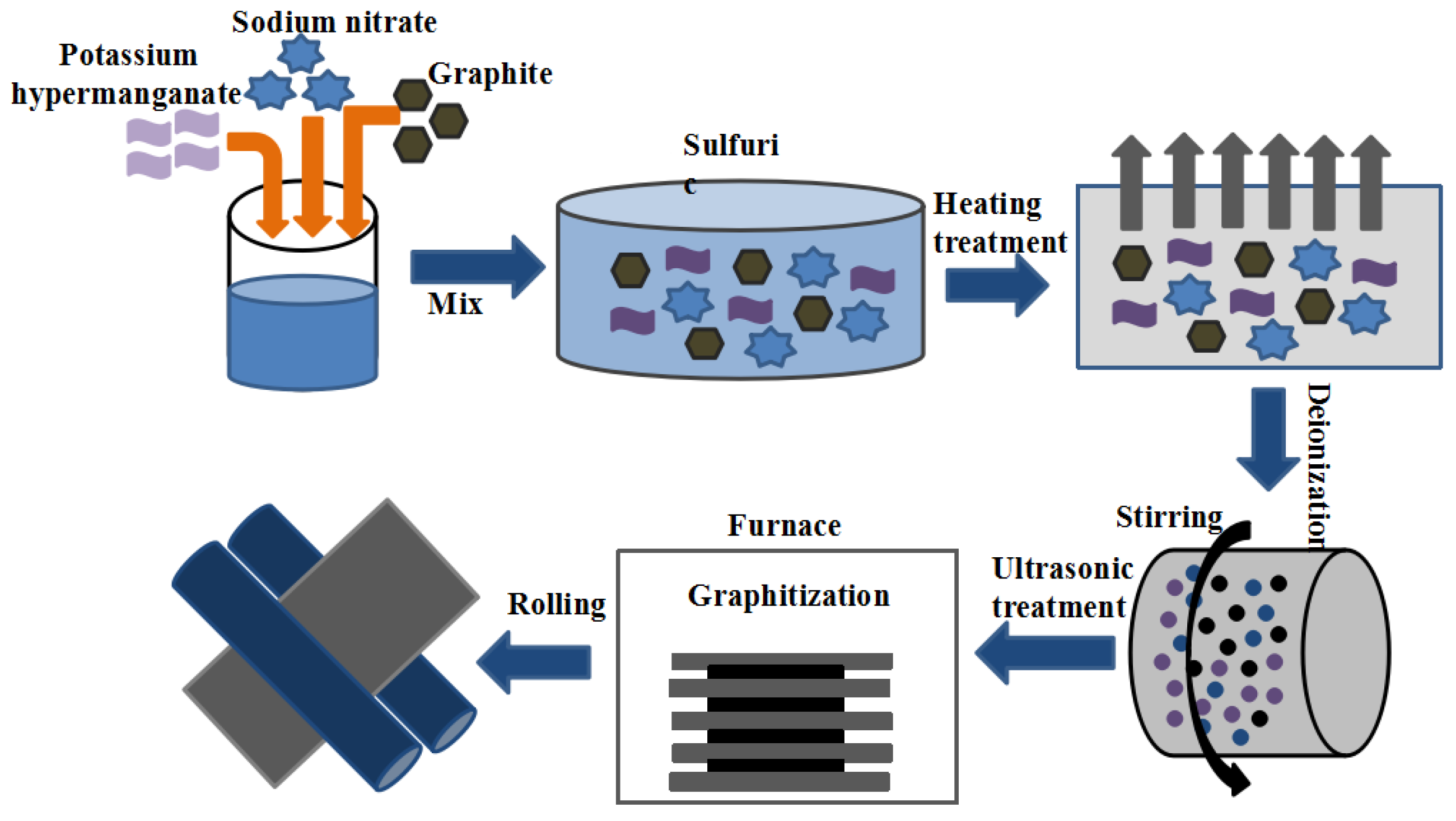
2.3. Preparation of Graphene Films

According to the mass ratio of 2:1:6, the graphite, sodium nitrate and potassium permanganate are, respectively, weighed and fully mixed under the condition of an ice bath to obtain the mixture. The mixture is placed in concentrated sulfuric acid at a solid–liquid ratio of 0.02–0.03 g/mL, and reacted in a beaker for 12 h, stirring until a pulpy substance appears. Stir in the beaker while adding deionized water, then move the beaker into a 90 °C constant temperature water bath for 7 h, add hydrogen peroxide and continue stirring for 30 min to obtain the solution. The graphene solution is obtained by ultrasonic treatment after multiple centrifugations (centrifugal speed 9000–13,500 rpm).
An 8 mL graphene solution (8 mg/mL) is evenly mixed with different volumes of carbon-rich molecule (CRM) solutions (1.2 mg/mL), as shown in Table 1. The mixed solution is magnetically stirred for 30 min, and then poured into the polytetrafluoroethylene dish. Then, the polytetrafluoroethylene dish is placed in the drying oven, the temperature is adjusted to 60 °C, the time is set to 6 h and the self-supporting composite film with a different quality score of CRMs can be obtained.
The composite film is placed in the furnace at 5 °C/min; it is heated at 250 °C for 1 h and then heated at 5 °C/min to 800 °C for 1 h under nitrogen protection. Then, under the protection of argon, the graphitization process is carried out in a high-temperature graphitization furnace at a heating rate of 20 °C/min to 2800 °C, held for 1 h and then cooled naturally to room temperature. Finally, the graphene composite film can be obtained by rolling the composite film, as shown in Figure 1.

2.4. Characterization

The cross-sectional morphology of graphene films is characterized by a scanning electron microscope (Gemini SEM 360, Dong Guang, China). The structure and phase of the film are analyzed by a Raman spectrometer (HORIBA Jobin Yvon, Grabels, France) and (Thermo-Fisher ESCALAB 250Xi (XPS), Waltham, MA, USA). The thermal diffusivity of graphene films is measured by a laser flash thermal conductivity meter (Netzsch LFA 467, Selb, Germany). The heat dissipation effect of the graphene film is tested by a micro-infrared test system.

3. Results

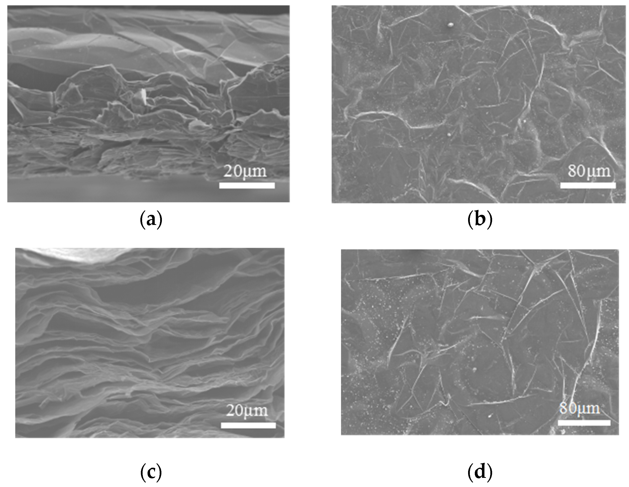
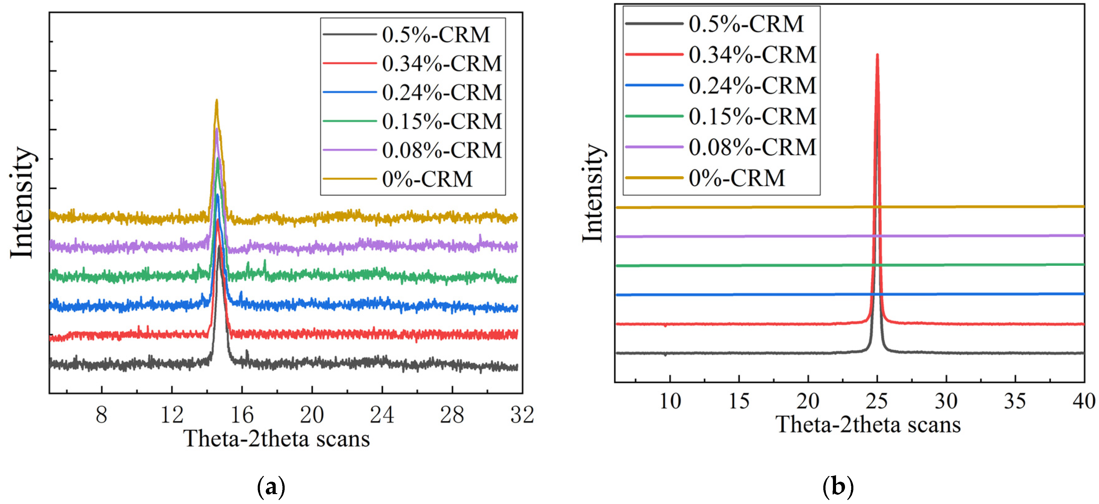
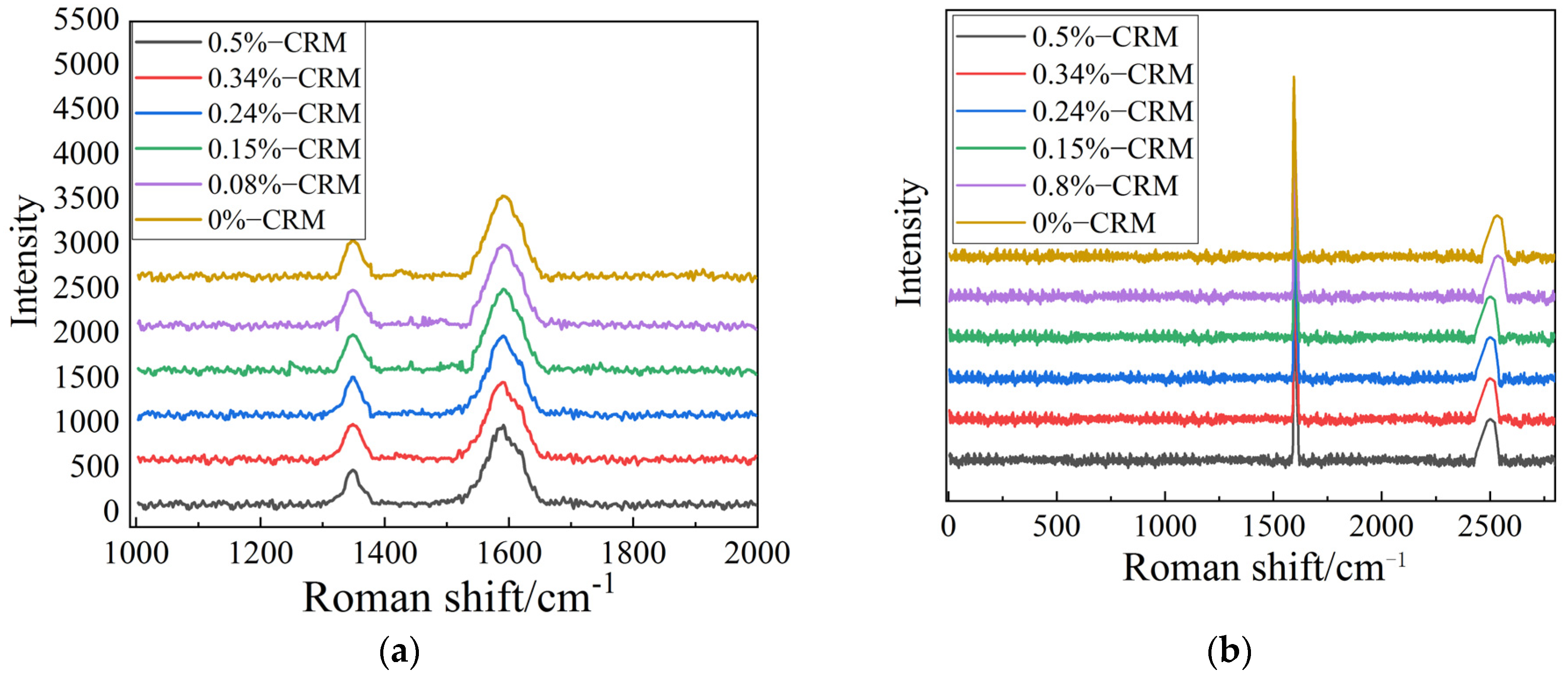
3.1. Effect of Adding Carbon-Rich Molecules to Graphene Films

Figure 2a,c show that the two scanning electron microscopy images have a typical layer stacking structure, compared with the cross-section of the graphene film in Figure 2a; the SEM image of Figure 2c shows that a continuous layered structure and channels are formed in the graphene film with 0.15% mass fraction of CRMs.
The film forms a continuous strip and channel, which provides an important path for the rapid escape of gas in the subsequent reduction process, avoiding the film rupture caused by gas release. In addition, when the graphene film forms an ordered layered structure, this structure contributes to the efficient transport of phonons. Because phonons are the main carrier of heat transfer in solids, the ordered structure reduces phonon scattering and defects, which allows heat energy to be transferred more quickly through the continuous layered structure and channels. This means that their effective transfer can significantly improve the thermal conductivity efficiency of materials. This phenomenon has also been confirmed by Ruo-Han Niu [28].
After adding 0.15% mass fraction of CRMs to the graphene film, the rolled graphene film shows a compact and orderly internal structure, the interlayer gap is significantly reduced, the density of the film increased the structure is more dense, the contact between layers is closer and the thermal resistance is significantly reduced.
As shown in Figure 2b,d, there is no significant difference between the surface of the graphene film and that of the graphene film with the addition of a mass fraction of 0.15% CRMs.
Figure 3a,b show the XRD patterns of graphene film with different contents of carbon-rich molecules (CRMs) before and after graphitization. Before graphitization, as shown in Figure 3a, due to the presence of oxygen-containing functional groups in the GO lamellar, the diffraction peak of the GO film appeared at 2θ = 14°, and the corresponding layer spacing is 0.7982 nm. With the increase in the mass fraction of CRMs, the diffraction peaks of GO/CRM composite films are basically the same as those of the GO film, and there is no significant change in peak location, indicating that the introduction of CRMs does not cause a significant change in GO crystal structure.
After high-temperature graphitization, as shown in Figure 3b, the diffraction peak of graphene film with different contents of carbon-rich molecules appears at 2θ = 25.44°, corresponding to layer spacing d = 0.3368 nm, which is very close to the layer spacing of HOPG (0.3354 nm) [29]. The results show that the oxygen-containing functional groups in GO are completely removed after high-temperature graphitization. Since phonon scattering affects the vibration and relative position between graphene layers, thereby changing the layer spacing of the wave crest, the layer spacing of the graphene film is reduced from 0.7982 nm to 0.3368 nm, meaning that the stack of graphene layers becomes more compact, and the interaction between the graphene layers is enhanced, which means there is better load transfer efficiency and helps to form a more stable graphene structure. The validity of this conclusion has also been verified by Niu, Tianqi Bai [30]. This result also shows that the graphene film not only eliminates the functional group but also has a higher degree of orientation.
As shown in Figure 4a, the D-peak at about 1350 cm−1 indicates lattice distortions and other defects in the graphene surface or at the graphene edge [31,32,33]. Prior to graphitization, graphene films introduce a large number of lattice defects and oxygen-containing functional groups due to the harsh oxidation treatment process. Therefore, graphene films have poor crystallinity. When the carbon-rich molecules are added, the ID/IG ratio (about 0.7) did not change significantly, indicating that the introduction of CRMs did not disturb the crystal structure of graphene films.
After high-temperature graphitization, as shown in Figure 4b, the D-peak gradually decreases, while the G-peak increases and becomes sharp, indicating that the addition of CRMs promotes the recovery of the sp2 lattice domain in GO/CRM films. When the quality score of CRMs relative to GO increases from 0.08% to 0.24%, the ID/IG ratio decreases from 0.13 to 0.06. The results show that the introduction of external carbon sources during the graphitization treatment helps to restore the aromatic structure inside the graphene and improves the crystallinity of the graphene film. During the graphitization process, intercalated CRMs are used as an external carbon source to restore structural defects in the graphene sheets. When the mass fraction of CRMs increases from 0.24% to 0.5%, the ID/IG ratio is gradually increased from 0.06 to 0.16, indicating that excessive CRMs would lead to aggregation and the formation of disordered structures during graphitization [33].

3.2. Effect of Carbon-Rich Molecules on Thermal Conductivity of Graphene Film

Figure 5 shows the thermal diffusivities and thermal conductivities of graphene film with different mass fractions of CRMs. The specific heat capacity of the graphene composite film is 0.76 J/(g·K), and the density is normalized to 1.86 g/cm3. As shown in Figure 5, when the mass fraction of CRMs increases from 0 to 0.24%, the in-plane thermal conductivity of the composite film increases from 598.74 W/(m·K) to 704.27 W/(m·K). With the increase in the mass fraction of CRMs from 0.24% to 0.5%, the in-plane thermal conductivity shows an upward trend, which can be attributed to the repair of lattice defects in graphene and the removal of oxygen-containing functional groups, as well as the recovery of the sp2 graphene carbon domain. During high-temperature graphitization, CRMs act as an external carbon source to repair structural defects in graphene. With the further increase in the mass fraction of CRMs from 0.24% to 0.5%, the in-plane thermal conductivity of graphene composite film gradually decreases from 704.27 to 460.32 W/(m·K). The reason for the decrease in thermal conductivity can be attributed to the excessive addition of CRMs that may act as a scattering point for phonons, which has a negative impact on heat dissipation performance. The results of thermal conductivity are in agreement with those of XRD and Raman analysis.

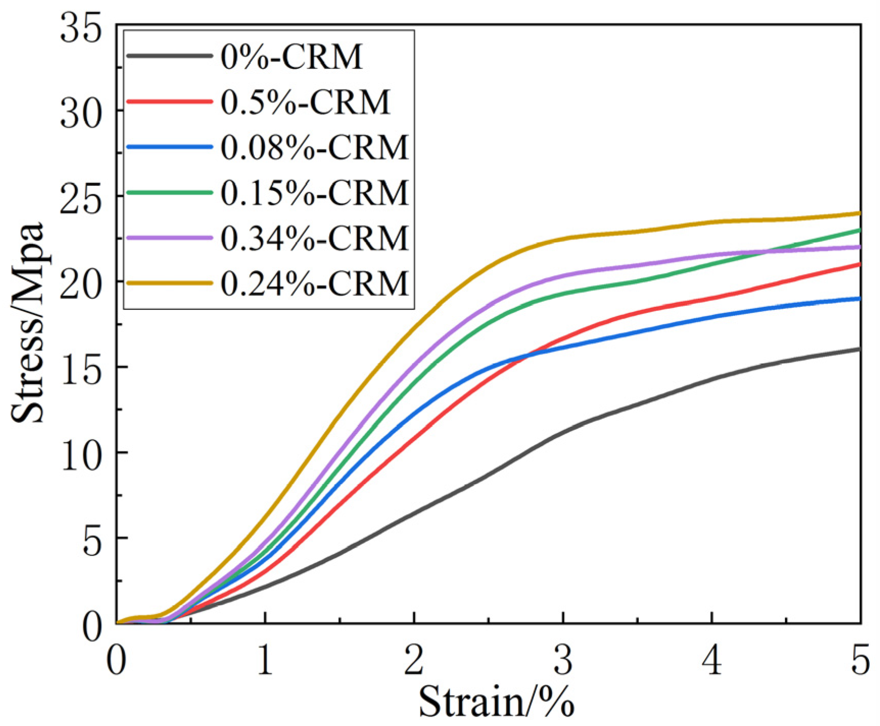
3.3. Effect of Carbon-Rich Molecules on Mechanical Properties of Graphene Film

In order to better analyze the mechanical properties of the graphene film with CRMs applied to the car seat in the winter environment, the experimental ambient temperature environment is selected as 0 °C. The test results are shown in Table 2.
Table 2 shows the stress–strain curves of graphene films with different mass fraction CRMs at an ambient temperature of 0 °C. As the mass fraction of CRMs changes from 0% to 0.24%, the elastic modulus of the graphene film gradually increases from 949.44 Mpa to 1267.52 Mpa, and the maximum tensile force of the graphene film also increases from 18.32 N to 25.67 N; this is because the addition of CRMs will cause the chemical bonds of graphene films to become stronger, so the mechanical properties are enhanced. However, as the mass fraction of CRMs continues to increase from 0.24% to 0.5%, the elastic modulus of the graphene film begins to decrease, and the maximum tensile force also becomes smaller. This indicates that the addition of excessive CRMs will increase the defects of the graphene film, which is not conducive to the enhancement of the mechanical properties of the graphene film; this also corresponds to the previous Roman and thermal conductivity test results.
The stress–strain curve results of graphene films also show similar regular changes in Figure 6. As the mass fraction of CRMs increases from 0% to 0.24%, the area of the stress–strain curve and the x-axis gradually increases, the graphene film is less prone to fracture and the mechanical stability becomes stronger. At this stage, the interaction between the graphene film and the CRMs becomes stronger and the mechanical properties become larger. As the mass fraction of the CRMs increases from 0.24% to 0.5%, the area of the stress–strain curve and the x-axis gradually decreases, the chemical bond between the graphene film and the CRMs becomes weaker, and the overall mechanical properties of the graphene film gradually decrease.

3.4. The Heat Dissipation Capacity of Graphene Films

In order to further elaborate on the role of carbon-rich molecules in repairing the structural defects of graphene films, the temperature distribution of graphene films is analyzed using an infrared thermal imaging camera. Comparing the results of Figure 7a,b, it can be seen that under the heating condition of 60 °C, the color of pure graphene film is dark red and the temperature reaches 55 °C, while the surface temperature of the graphene film with a mass fraction of 0.24% CRMs is about 10% lower than that of the graphene film, and the temperature can reach 50 °C. The same phenomenon occurs in the same situation, as shown in Figure 7c,d. Under the heating condition of 50 °C, the color of the graphene film is red and the temperature reaches 42 °C, but the color of the graphene film with a mass fraction of 0.24% CRMs is orange and the temperature can reach 37 °C. In addition, the temperature distribution inside the film is relatively uniform, and the temperature rise at the edge of the film is caused by the interface contact between the film and the hot plate. In conclusion, the heat transfer performance of graphene films with a mass fraction of 0.24% CRMs is better than that of pure graphene films, which further proves that the use of carbon-rich molecules can effectively repair large topological defects within the graphene oxide sheets, thereby improving the structural integrity of graphene films, reducing phonon scattering caused by the existence of defects and greatly improving the heat dissipation performance of the graphene film.

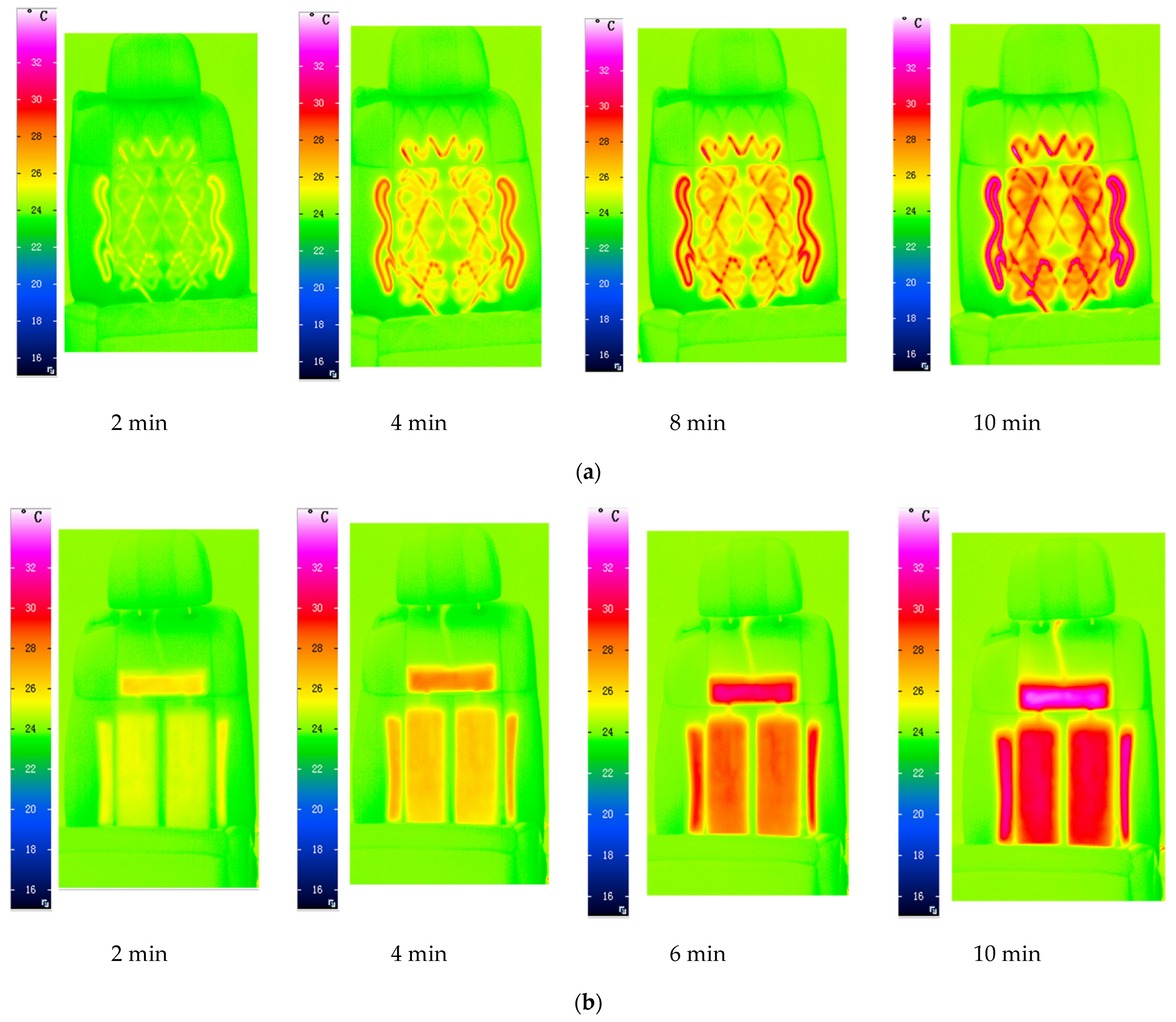
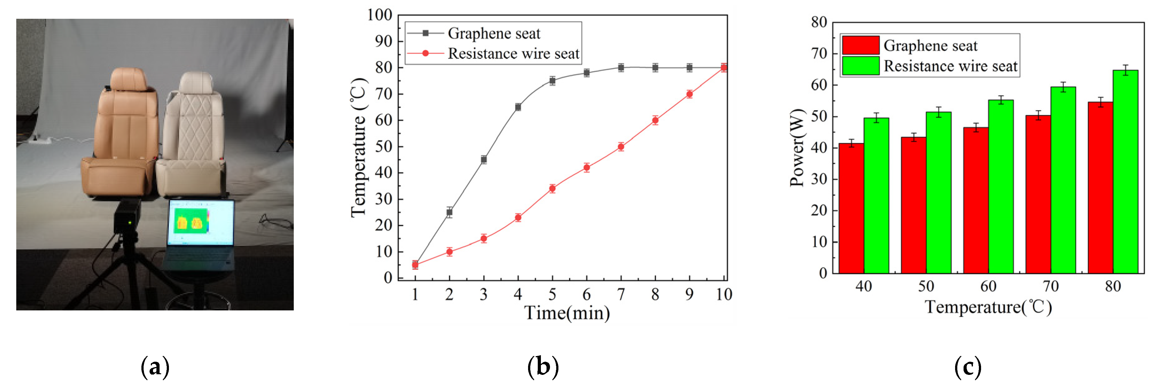
3.5. Evaluating the Heat Dissipation Effect of Graphene Film on the New Energy Car Seats

In the low-temperature environment in winter, the heating function of the car seat surface is becoming more and more demanding. At present, most car seats use resistance wire heating to transfer energy to the seat surface, but this way has the following problems of low heat conversion efficiency, a slow heating speed and uneven heating. Therefore, in order to verify the heat dissipation effect of graphene film applied to new energy vehicle seats, the heat dissipation effects of the graphene seat with a mass fraction of 0.24% CRMs and the resistance wire seat are compared and analyzed.
Figure 8 shows the infrared distribution of the graphene film seat and resistance wire seat. Figure 8a shows that with the increase in time, the infrared distribution map of the resistance wire seat shows an uneven state as a whole; the heating area is mainly concentrated around the resistance wire. With the increase in time, the radiation temperature of the resistance wire seat grows higher, and the color becomes redder. Figure 8b shows the infrared distribution of the graphene seat. The seats made of graphene films show a uniform distribution of the temperature field, and with the increase in time, the temperature also rises, and the radiation intensity is also greater.
To verify that seats containing graphene films have faster heating times and higher efficiency, the experimental data of the power consumption from the graphene seat and the resistive wire seat are added, and the heating time of the graphene film applied to the new energy seat is analyzed in detail.
Figure 9a shows an experimental diagram of the graphene seat and resistive wire seat. Figure 9b shows the temperature rise chart of resistive wire seats and graphene seats. Compared with the resistance wire seat, the heating rate of the graphene seat is significantly larger, rapidly reaching 80 °C within 5 min, and then hovering around 80 °C, while the resistance wire seat rises to 80 °C at a more uniform rate. When the heating time is 3 min, the graphene seat can be heated to 45 °C, while the resistance wire seat is only heated to 23 °C. When both types of seats are equally heated to 50 °C, the graphene seat reaches this temperature and can be used in only 3.5 min, while the resistance wire seat can be used in 7 min, meaning the graphene seat has a faster heating rate than the resistive wire seat.
Figure 9c shows the power consumption of the resistive wire and graphene seats. When both seats are kept at the same temperature of 50 °C, the graphene seat consumes 43.4 W of power, while the resistance wire seat requires 51.4 W of power, so the graphene seat consumes about 20 percent less power than the resistive wire seat. The same results are also obtained when the temperature changes from 40 °C to 80 °C; the graphene seat consumes less power than that of the resistive wire seat.
In summary, the appropriate addition of CRMs helps to form continuous layered structures and channels, restore the aromatic structure of graphene and improve the crystallinity of graphene films. This will help increase the thermal conductivity and mechanical properties of graphene films. When graphene film is applied to the car seat, the experimental results show that compared with the traditional resistance wire seat, the graphene seat has a faster heating rate and higher energy efficiency.

4. Conclusions

Graphene has a wide range of applications in electronic equipment, energy equipment and heat dissipation in advanced materials. Graphene seats are expected to be widely used in the new energy vehicle market, the heat dissipation problem has become an important factor restricting its performance and life, and graphene has become an ideal choice for the next generation of electronic heat dissipation materials with its excellent thermal conductivity. However, in the process of graphene preparation, there are some problems such as harsh experimental conditions, inconvenient operation and environmental pollution. Thus, this study presents a new method to prepare graphene film by adding carbon-rich molecules.
The experimental results show that the addition of CRMs with a mass fraction from 0~0.24% during the graphitization treatment helps to restore the aromatic structure inside the graphene, which will lead to the improvement in the thermal conductivity of the graphene film. However, the addition of excessive carbon-rich molecules can lead to the formation of disordered structures in graphene films, which results in a decrease in the thermal conductivity of the graphene film.
The graphene films with carbon-rich molecules have better heat dissipation characteristics and mechanical stability. The in-plane thermal conductivity of the composite film can be increased from 598.74 W/(m·K) to 704.27 W/(m·K). The surface temperature of graphene films with CRMs is about 10% lower than that of pure graphene films. When graphene is applied to new energy car seats, compared with traditional resistance wire seats, graphene seats have the characteristics of uniform heating, a fast heating speed and higher energy efficiency.
The results of this study provide an effective method for repairing structural defects in graphene, with the continuous development of graphene preparation technology and cost reduction. In the future, graphene films will also be used in technical fields such as electronic and optoelectronic devices, energy storage and flexible sensors. Graphene films will also lead to great developments in the fields of quantum dot-derived materials and medical imaging.

Author Contributions

Conceptualization, X.Z. and X.J.; methodology, X.Z.; validation, Xin Jia and X.Z.; formal analysis, X.Z.; data curation, X.J.; writing—original draft preparation, X.Z.; writing—review and editing, X.Z.; supervision, X.J.; funding acquisition, X.Z. All authors have read and agreed to the published version of the manuscript.

Funding

This research was funded by the Science and Technology Plan Project of Beijing Municipal Administration for Market Regulation grant number [SJKJXM-2023-001], Science and Technology Program Project of the State Administration for Market Regulation grant number [2022MK003], And Fundamental Research Funds for NIM was funded by [AKYCX2311].

Data Availability Statement

The original contributions presented in this study are included in the article. Further inquiries can be directed to the corresponding author(s).

Conflicts of Interest

The authors declare no conflicts of interest.

References

  1. Chen, K.X.; Gao, L.Y.; Li, Z.; Sun, R.; Liu, Z.Q. Research Progress of Electroplated Nanotwinned Copper in Microelectronic Packaging. Materials 2023, 16, 4614. [Google Scholar] [CrossRef] [PubMed]
  2. Xin, G.; Sun, H.; Hu, T.; Fard, H.R.; Sun, X.; Koratkar, N.; Borca-Tasciuc, T.; Lian, J. Large-area freestanding graphene paper for superior thermal management. Adv. Mater. 2014, 26, 4521–4526. [Google Scholar] [CrossRef] [PubMed]
  3. Wertz, J.T.; Kuczynski, J.P.; Boday, D.J. Thermally conductive-silicone composites with thermally reversible cross-links. ACS Appl. Mater. Interfaces 2016, 8, 56–64. [Google Scholar] [CrossRef]
  4. Raab, S.J.; Guschlbauer, R.; Lodes, M.A.; Körner, C. Thermal and electrical conductivity of 99.9% pure copper processed via selective electron beam melting. Adv. Eng. Mater. 2016, 18, 1661–1666. [Google Scholar] [CrossRef]
  5. Hu, Y.; Du, G.; Chen, N. A novel approach for Al2O3/epoxy composites with high strength and thermal conductivity. Compos. Sci. Technol. 2016, 124, 25–32. [Google Scholar] [CrossRef]
  6. Zhang, Q.; Huang, J.; Qian, W.; Zhang, Y.; Wei, F. The road for nanomaterials industry: A review of carbon nanotube production, posttreatment, and bulk applications for composites and energy storage. Small 2013, 9, 1237–1265. [Google Scholar] [CrossRef]
  7. Balandina, A.A.; Nika, D.L. Phononics in low-dimensions: Engineering phonons in nanostructures and graphene. Mater. Today 2012, 15, 266. [Google Scholar]
  8. Song, S.H.; Xu, Z.; Liu, Z. Enhanced Thermal Conductivity of Graphene-Based Polymer Composites for Heat Sink Applications. Carbon 2016, 100, 628–635. [Google Scholar]
  9. Xu, X.; Li, X.; Fang, M.; Wang, W. Graphene Films for Next-Generation Thermal Management in Electronics. Adv. Funct. Mater. 2020, 30, 7–15. [Google Scholar]
  10. Baiocco, G.; Genna, S. Electrophoretic deposition of graphene coating on copper for improved thermoelectric performance of wire rods. Int. J. Adv. Manuf. Technol. 2024, 133, 5761–5776. [Google Scholar] [CrossRef]
  11. Seol, J.H.; Jo, I.; Moore, A.L.; Lindsay, L.; Aitken, Z.H.; Pettes, M.T.; Li, X.; Yao, Z.; Huang, R.; Broido, D.; et al. Two-dimensional phonon trans port in supported graphene. Science 2010, 328, 213–216. [Google Scholar] [CrossRef] [PubMed]
  12. Shen, B.; Zhai, W.T.; Zheng, W.G. Ultrathin flexible graphene film: An excelle nt thermal conducting material with efficient EMI shielding. Adv. Funct. Al Mater. 2014, 24, 4542–4548. [Google Scholar] [CrossRef]
  13. Kumar, P.; Shahzad, F.; Yu, S.; Hong, S.M.; Kim, Y.-H.; Koo, C.M. Large-area reduced graphene oxide thin film with excellent thermal conductivity and electromagnetic interference shielding effectiveness. Carbon 2015, 94, 494–500. [Google Scholar] [CrossRef]
  14. Meng, X.; Pan, H.; Zhu, C.; Chen, Z.; Lu, T.; Xu, D.; Li, Y.; Zhu, S. Coupled chiral structure in graphene-based film for ultrahigh thermal condu ctivity in both in-plane and through-plane directions. ACS Appl. Mater. Interfaces 2018, 10, 22611–22622. [Google Scholar] [CrossRef] [PubMed]
  15. Deng, D.; Xiong, X. Free-standing paper-like heat spreading films based on graphene oxide-aromatic molecule c omposites. J. Mater. Sci. Mater. Ls Electron. 2018, 29, 3050–3055. [Google Scholar] [CrossRef]
  16. Dai, B.; Fu, L.; Liao, L.; Liu, N.; Yan, K.; Chen, Y.; Liu, Z. High-quality single-layer graphene via repar ative reduction of graphene oxide. Nano Res. 2011, 4, 434–439. [Google Scholar] [CrossRef]
  17. Song, N.; Cui, S.Q. Layered nanofibrillated cellulose hybrid films as flexible lateral heat spreaders: The effect of graphe ne defect. Carbon 2017, 115, 338–346. [Google Scholar] [CrossRef]
  18. Haskins, J.; Kınacı, A.; Sevik, C.; Sevinçli, H.; Cuniberti, G.; Çağın, T. Control of thermal and electronic transport in defect-engineered graphene nanoribbons. ACS Nano 2011, 5, 3779–3787. [Google Scholar] [CrossRef]
  19. Zhang, H.J.; Lee, G.; Cho, K. Thermal transport in graphene and effects of vacancy defects. Phys. Rev. B 2011, 84, 115460. [Google Scholar] [CrossRef]
  20. Nika, D.L.; Balandin, A.A. Two-dimensional phonon transport in graphene. J. Phys. Condens. Matter 2012, 24, 233203. [Google Scholar] [CrossRef]
  21. Zhao, W.; Wang, Y.; Wu, Z.; Wang, W.; Bi, K.; Liang, Z.; Yang, J.; Chen, Y.; Xu, Z.; Ni, Z. Defect-engineered heat transport in graphene: A route to highefficient thermal rectification. Sci. Rep. 2015, 5, 11962. [Google Scholar] [CrossRef] [PubMed]
  22. Zhu, D.; Pu, H.; Lv, P.; Zhu, Z.; Yang, C.; Zheng, R.; Wang, Z.; Liu, C.; Hu, E.; Zheng, J.; et al. Healing of reduced graphene oxide with methane hydrogen plasma. Carbon 2017, 120, 274–280. [Google Scholar] [CrossRef]
  23. Li, H.; Dai, S.; Miao, J.; Wu, X.; Chandrasekharan, N.; Qiu, H.; Yang, J. Enhanced thermal conductivity of graphene/ polyimide hybrid film via a novel “molecular welding” strategy. Carbon 2018, 126, 319–327. [Google Scholar] [CrossRef]
  24. Ren, S.; Liu, B.; Wang, M.; Han, G.; Zhao, H.; Zhang, Y. Highly Bright Carbon Quantum Dots for Flexible Anti-counterfeiting. J. Mater. Chem. C 2022, 1039, 23–31. [Google Scholar] [CrossRef]
  25. Wu, P.; Gao, L.; Lv, Z.; Zhang, D. Research progress of carbon quantum dots in metal corrosion protection. Corros. Prot. 2022, 43, 83–87. [Google Scholar]
  26. Wang, Y.; Zhang, L.; Liu, J. Bioinspired Carbon Quantum Dots Nanofluid Fabricated by a Facile Two-Step Synthesis toward High Performance Lubrication. ACS Appl. Mater. Interfaces 2023, 15, 4567–4578. [Google Scholar]
  27. Qin, T.; Deng, L.; Zhang, N.; Zhang, P.; Liu, Y.; Qin, L.; Huang, S.; Qiu, L.; Peng, S. Flexible polyaniline/carbon quantum dots films for enhanced electrochromic performance. Ceram. Int. 2024, 50, 53254–53263. [Google Scholar] [CrossRef]
  28. Niu, R.-H.; Li, Y.-W.; Ma, S.-L.; Yi, Z.-L.; Xie, L.-J.; Su, F.-Y.; Jia, H.; Chen, C.-M. Asymmetric structure endows thermal radiation and heat conduction in graphene films for enhancing dual-mode heat dissipation. J. Mater. Chem. A Mater. Energy Sustain. 2025, 11, 7890–7902. [Google Scholar] [CrossRef]
  29. Gang, Z.; Miao, Z.; Liu, Y.; Huang, J.; Chen, F.; Fu, Q. High thermal conductivity and increased thickness graphene nanosheet films prepared through metal ion-free route. Ceram. Int. 2022, 48, 3711–3719. [Google Scholar] [CrossRef]
  30. Bai, T.; Huang, K.; Liu, F.; Shi, R.; Ren, W.; Pei, S.; Gao, P.; Liu, Z. Nanoscale Mechanism of Microstructure-Dependent Thermal Diffusivity in Thick Graphene Sheets. Acta Phys. Chim. Sin. 2025, 41, 25–32. [Google Scholar] [CrossRef]
  31. Peng, L.; Xu, Z.; Liu, Z.; Guo, Y.; Li, P.; Gao, C. Ultrahigh thermal conductive yet super flexible graphene films. Adv. Mater. 2017, 29, 270–289. [Google Scholar] [CrossRef]
  32. Xiong, K.; Yang, T.; Sun, Z.; Ma, C.; Wang, J.; Ge, X.; Qiao, W.; Ling, L. Modified graphene film powder scraps for repreparation of highly thermally conductive flexible graphite heat spreaders. Carbon 2024, 11, 8–27. [Google Scholar]
  33. Miao, J.; Li, H.; Qiu, H.; Wu, X.; Yang, J. Graphene/PANI hybrid film with enhanced thermal conductivity by in situ polymerization. J. Mater. Sci. 2018, 53, 8855–8865. [Google Scholar] [CrossRef]
Figure 1. Schematic diagram of graphene film preparation.
Coatings 15 00560 g001
Figure 2. Scanning electron microscopy of graphene film cross-sections. (a) The cross-section of the graphene film. (b) The interface of the graphene film. (c) The cross-section of the 0.15% CRM–graphene film. (d) The interface of the 0.15% CRM–graphene film.
Coatings 15 00560 g002
Figure 3. XRD pattern of graphene film with different mass fraction of CRMs. (a) Pre-graphitization; (b) post-graphitization.
Coatings 15 00560 g003
Figure 4. Raman diagram of graphene film. (a) Pre-graphitization; (b) post-graphitization.
Coatings 15 00560 g004
Figure 5. Thermal diffusivities and thermal conductivities of graphene film.
Coatings 15 00560 g005
Figure 6. Stress–strain curves of graphene films with different mass fractions of CRMs.
Coatings 15 00560 g006
Figure 7. Infrared distribution of graphene films. (a) Graphene film at 60 °C. (b) Graphene film with mass fraction of 0.24% CRMs at 60 °C. (c) Graphene film at 50 °C. (d) Graphene film with mass fraction of 0.24% CRMs at 50 °C.
Coatings 15 00560 g007
Figure 8. Infrared distribution of graphene film seat and resistance wire seat. (a) Infrared distribution of resistance wire seat; (b) infrared distribution of graphene film seat.
Coatings 15 00560 g008
Figure 9. Temperature rise chart and power consumption of resistive wire seats and graphene seats. (a) The seats made of resistive wire and graphene seats. (b) Temperature rise chart of resistive wire and graphene seats. (c) Power consumption of resistive wire and graphene seats.
Coatings 15 00560 g009
Table 1. Quality score of CRM additions relative to GO content.
Sample Number123456
CRM quality score%0.000.080.150.240.340.5
Table 2. Mechanical stability of graphene films.
Ambient Temperature/°C Mass Fraction of CRMs/%Modulus of Elasticity/MpaMaximum Tensile
Force/N
00949.44 18.32
0.081015.8221.13
0.151198.4323.14
0.241267.5225.67
0.341199.3223.02
0.51023.3521.24
Disclaimer/Publisher’s Note: The statements, opinions and data contained in all publications are solely those of the individual author(s) and contributor(s) and not of MDPI and/or the editor(s). MDPI and/or the editor(s) disclaim responsibility for any injury to people or property resulting from any ideas, methods, instructions or products referred to in the content.

