Article

The Microstructure and Properties of Laser-Cladded Ni-Based Self-Fluxing Alloy Coatings Reinforced by TiC Particles

Welding Department, Faculty of Mechanical Engineering, Silesian University of Technology, Konarskiego Street 18A, 44-100 Gliwice, Poland
*
Authors to whom correspondence should be addressed.
Coatings 2025, 15(5), 527; https://doi.org/10.3390/coatings15050527 (registering DOI)
Submission received: 27 March 2025 / Revised: 22 April 2025 / Accepted: 27 April 2025 / Published: 28 April 2025
(This article belongs to the Special Issue Welding Techniques in Surface Engineering)

Abstract

:
In this study, NiCrBSi composite coatings reinforced with 5–15 wt.% TiC particles were prepared using laser cladding to investigate the influence of the TiC content and laser beam power on the coatings’ quality, structure, and properties. Penetrant tests revealed the presence of cracks in the composite coatings, which were reduced with the higher laser power due to a decrease in cooling rate. A macroscopic analysis showed that pure NiCrBSi coatings exhibited a high quality and were free of defects, while the addition of TiC particles led to the formation of large pores, particularly in coatings produced with a lower laser power. Microstructural characterization was conducted using Scanning Electron Microscopy (SEM), Energy-Dispersive Spectroscopy (EDS), and X-ray Diffraction (XRD). The microstructure of the pure NiCrBSi coatings consisted of an austenitic matrix with chromium-based precipitates (carbides and borides). Variations in structural morphology across different regions of the coatings and under varying laser powers were described. When TiC particles were added, partial dissolution occurred in the molten pool, enriching it with titanium and carbon, which subsequently led to the precipitation of titanium carbides. The average microhardness of the composite coatings increased by 28%–40% compared to the pure NiCrBSi coating, while the erosion resistance remained comparable. Solid particle erosion tests in accordance with the ASTM G76-18 standard resulted in average erosion values of the pure NiCrBSi coating of 0.0056 and 0.0025 mm3/g for the 30° and 90° impingement angles, respectively.

Graphical Abstract

1. Introduction

Nickel-based self-fluxing alloys are widely used for fabricating coatings on machine parts in various industrial applications to increase their durability (mainly for components operating in corrosion or wear conditions in aerospace, automotive, and chemical industries, engines, molds, tools, etc.) [1,2,3]. In general, the self-fluxing alloys are a group of alloys with a wide range of compositions. The examples of the commercial names of such alloys are as follows: Ni60, Ni45, Metco 12C, Metco 16C, Eutalloy PE-3309, and Tafa 1275H. The nickel-based self-fluxing alloys commonly contain 10–20 wt.% of chromium, 1–4 wt.% of boron, 2–5 wt.% of silicon, and up to 1 wt.% of carbon. This composition provides high corrosion resistance due to the chromium addition. Carbon promotes the hard phases’ precipitation in the structure, causing an improvement in hardness and wear resistance. In addition, boron and silicon are deoxidizers and improve fluxing properties (they reduce the melting point, protect from oxidation by forming borosilicates, and improve the wettability). Moreover, other elements may be added to the alloys’ compositions, for example, Fe, Mo, Mn, Co, and W [4,5,6]. Nickel-based self-fluxing alloy coatings may be fabricated using various surface treatment technologies including the plasma-transferred arc (PTA) or laser cladding processes and flame, plasma, or high-velocity oxy-fuel (HVOF) spraying processes [7,8,9,10,11]. Laser cladding, in comparison to other surface treatment technologies, due to the high energy density, allows for the rapid melting and solidification of the coatings. Due to that, the impact on the structure, properties, and deformations of the base material is minimal, but the coatings are metallurgically bonded with minimal dilution. The high temperature gradient promotes the formation of a fine microstructure. Laser cladding technology with the use of powdered materials allows for the selection of the coating material composition in a wide range, including the type and amount of the reinforcing particles, making it adaptable for various industrial applications. It also lowers the production costs by a reduction in the need for extensive machining, as the coatings’ thickness may be shaped by the process parameters’ optimization [12].
Currently, there is an increased interest in the field of metal matrix composite coating manufacturing to improve the surface wear resistance of machine parts to extend their operation times. Various wear mechanisms (e.g., adhesion, abrasion, and erosion) cause damage to the machine parts, which necessitates their repair or replacement. Providing better surface wear resistance is very important as it allows for a reduction in operating costs [13,14,15,16]. It has been proven that the metal matrix composite coatings, due to the combination of hard ceramic particles with a tough metallic matrix, provide higher wear resistance compared to metallic coatings [17,18]. Some machine parts, for example, in the chemical, oil, marine, and mining industries, are exposed not only to wear mechanisms but also to corrosion and oxidation. For such parts, the nickel-based alloy coatings reinforced by ceramic particles can be used, to combine the corrosion and oxidation resistance of the matrix, together with the wear resistance by the composite microstructure [19].
As previous studies have shown, the laser cladding technology may be used to fabricate high-quality ex situ and in situ composite coatings characterized by a high homogeneity, fine-grained structure, strong metallurgical bonding with the substrate, and low dilution [20,21,22,23,24,25]. For the current research, the titanium carbide particles were selected to produce Ni-based composite coatings, due to their high hardness, thermal stability, strength, resistance to corrosion and oxidation, and low density [26,27]. Previous research in this field revealed that the addition of TiC particles to laser-cladded Ni-based coatings in various amounts improved the hardness and wear resistance of the coatings [28,29,30]. Chen et al. [31] conducted research on the laser cladding of Ni45 self-fluxing alloy coatings reinforced by 10 wt.% of titanium carbide particles. The used technology allowed us to fabricate uniform composite coatings having an average hardness of about 520 HV. Meng et al. [32] examined the effect of different addition methods of nano-TiC particles on the microstructure and properties of Ni-based self-fluxing alloy laser-cladded coatings. Yang et al. [33] used laser cladding to fabricate in situ composite coatings by mixing the titanium and graphite with the Ni-based self-fluxing alloy powder. Huang et al. [34] studied the influence of the laser cladding process parameters on the microstructure and wear resistance of Ni35A/TiC composite coatings.
Although some research has been conducted on the structure and properties of Ni-based self-fluxing alloy laser-cladded coatings reinforced with TiC particles, there is no information in the literature on the effect of the TiC addition on the erosive wear resistance of such coatings. The erosion studies’ results of different compositions of Ni-based self-fluxing alloy coatings produced using HVOF spraying or PTA cladding processes show that the erosion resistance of the surface may be improved, but the erosion behavior depends on many factors (microstructure, type, size, and quantity of the hard phases, as well as the properties of their interface with the matrix, erosive particles material, impingement angle, temperature, etc.) [4,35,36,37,38].
The main purpose of the current study was to test the influence of the 5–15 wt.% TiC particles’ addition to the NiCrBSi self-fluxing alloy powder on the structure, hardness, and erosion resistance of laser-cladded coatings. The tests included penetrant testing, and macrostructure and microstructure analysis using a Scanning Electron Microscope (SEM), with the Energy-Dispersive Spectroscopy (EDS) chemical composition analysis and X-ray Diffraction (XRD) phase identification analysis. The coatings’ properties were tested using the Vickers microhardness testing method and solid particle erosion tests.

2. Materials and Methods

2.1. Materials and Laser Processing

The laser-cladded metal matrix composite coatings were produced on the S355JR steel substrate (Table 1) (Cognor, Stalowa Wola, Poland) with dimensions of 100 mm × 100 mm × 10 mm. The substrate surface was prepared before the laser cladding process by grinding to surface finish of 0.5 μm Ra and degreasing with ethyl alcohol (Stanlab, Lublin, Poland). The Ni-based self-fluxing alloy Metco 15E (Table 1) (Oerlikon, Westbury, NY, USA) and 99.8% pure with the size of 50–150 μm TiC (Goodfellow, Huntington, UK) powders were used to produce the coatings. The powders were mixed with Ni-based alloy to TiC weight ratios of 100:0, 95:5, 90:10, and 85:15, and dried for 1 h at the temperature of 50 °C prior to the cladding process.
The laser cladding process was carried out using the testing stand equipped with a solid-state laser TRUMPF Trudisc 3302 (Table 2) (TRUMPF, Ditzingen, Germany), a numerical positioning-control system, and a gravitational powder feeder. The laser beam focus, with a diameter of 200 μm, was set 30 mm above the substrate surface. The powder was directly injected into the molten pool using a nozzle with an adapted shape and dimensions to the shape and dimensions of the liquid metal pool. Argon was used as the powder transporting and shielding gas with the 3 L/min and 25 L/min flow rates, respectively. The multi-run coatings were made with 40% overlap and the process was carried out without preheating (the interpass temperature was below 30 °C). The process parameters are summarized in Table 3.

2.2. Structure and Properties Testing

To assess the quality of the coatings, the penetrant tests using the color contrast technique were carried out using penetrant 68 NF, developer MR 70, and cleaner MR 79 (MR Chemie, Unna, Germany). The dwell and development times during tests were both 10 min.
The macrostructure investigation included macrostructure observations using a ZEISS Axio Observer A1 (ZEISS, Jena, Germany) featuring the homogeneity and quality of coatings, and geometrical dimensions measurements. The AutoCAD 2023 software (Autodesk, San Francisco, CA, USA) program was used to measure the dimensions of coatings including the cross-sectional areas of melted substrate (FBM) and coating (RA), which were used to calculate the dilution using Equation (1):
U = F B M F B M + R A × 100   [ % ]
The microstructure investigation included microstructure observations and Energy-Dispersive Spectroscopy (EDS) analysis which were conducted on a Scanning Electron Microscope (SEM) ZEISS EVO MA10 (ZEISS, Jena, Germany). The samples for those tests were etched at room temperature using a mixture of HNO3 (Chempur, Piekary Śląskie, Poland), acetic acid (Stanlab, Lublin, Poland), HCl (Chempur, Piekary Śląskie, Poland), and glycerol (Poch, Gliwice, Poland) (etchant 89 according to ASTM E407-99 Standard [39]). The X-ray Diffraction (XRD) test was performed using a PANalitycal X’Pert PRO (Malvern Panalitycal, Malvern, UK) diffraction system equipped with a cobalt anode. The profiles were obtained in a continuous scan mode within the 2θ range of 15° to 120°, a step size of 0.0525°, and a counting time per step of 53.805 s.
To assess the properties of the coatings, the Vickers microhardness measurements and the solid particle erosion tests were performed on samples N-2, T5-2, T10-2, and T15-2 according to Table 3, due to their better quality. The Vickers microhardness tests were carried out using a Future Tech FM-810 (FUTURE-TECH CORP., Kawasaki, Japan) Vickers microindentation tester in three lines perpendicular to substrate surface (from the coating’s surface towards the base material), with a distance between measuring points of 0.2 mm. A load of 500 g was used, and dwell time was 10 s. The average microhardness of coatings was calculated on the basis of 10 measurements.
The solid particle erosion tests were conducted in accordance with the ASTM G76-18 standard [40] using device manufactured in Welding Department, Silesian University of Technology, Gliwice, Poland. The 50 μm diameter angular Al2O3 abrasive particles in a stream of dry air were used as erodent material with a velocity of 70 m/s and feed rate of 2 g/min. The erodent was injected for 10 min onto the tested surface through a 1.5 mm diameter nozzle which was placed 10 mm above the sample. The coatings were tested with the impingement angles of 90° and 30°. For each angle and sample, three tests were performed. To determine average erosion test results (steady-state erosion rate (2) and erosion value (3) in accordance with ASTM G76-18 standard [40]), the mass loss was measured using a laboratory scale RADWAG AS 82/220.R2 PLUS (RADWAG, Radom, Poland) with an accuracy of 0.0001 g. The coatings’ densities were measured using the Archimedes method. To determine the erosive wear mechanisms, SEM microscopic observations of the craters were carried out using ZEISS EVO MA10 (ZEISS, Jena, Germany).
S t e a d y s t a t e   e r o s i o n   r a t e   m g m i n = M a s s   l o s s   [ m g ] T e s t   t i m e   [ m i n ]
E r o s i o n   v a l u e m m 3 g = V o l u m e   l o s s   m m 3 T o t a l   m a s s   o f   a b r a s i v e   p a r t i c l e s   [ g ]

3. Results and Discussion

3.1. Penetrant Testing

The images of the laser-cladded coatings’ surfaces after penetrant tests are presented in Figure 1. The tests revealed linear indications on most of the coatings, which were caused by the presence of cracks. In the case of the pure NiCrBSi coatings, cracks formed only in sample N-1, for which a lower laser beam power (lower energy) was used. When a higher energy was applied, the cooling rate decreased, leading to a reduction in cracks in the coatings due to the lower thermal stresses [41]. These results are consistent with the previously reported investigation of cracking behavior in Ni-based laser-cladded coatings by Shi et al. [42]. Due to the higher hardness and brittleness of the coatings with added TiC particles, cracks were observed in each of the analyzed coatings. As previously proven, a higher hardness increases the cracking tendency [43]. Similarly to the previously discussed Ni-based coatings, with the higher energy used during the laser cladding process, fewer cracks were formed due to the decrease in cooling rates and thermal stresses [41,42].

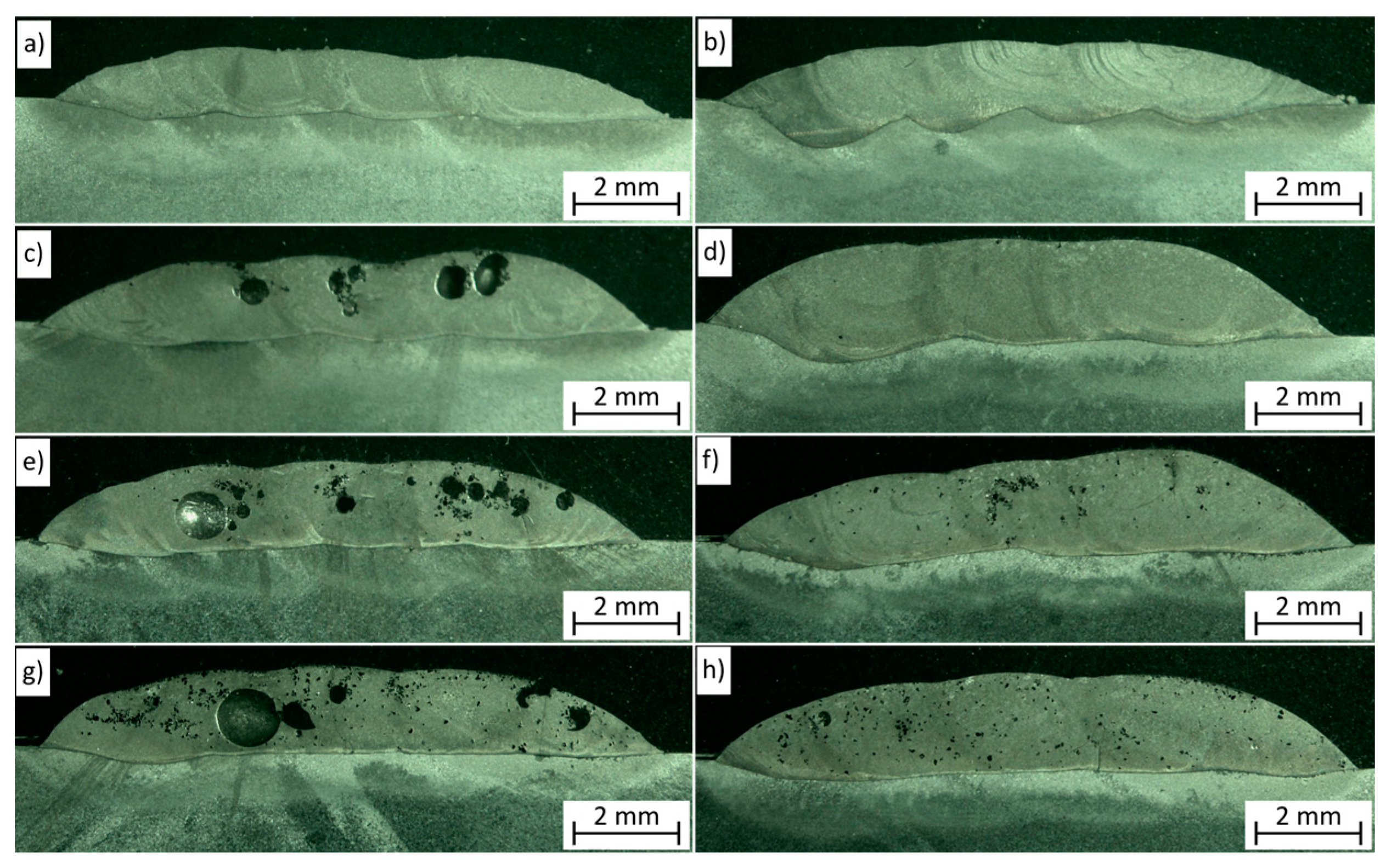
3.2. Macrostructure Analysis

The macrographs of the analyzed coatings are shown in Figure 2. The parameters of the coatings’ thickness and dilutions are summarized in Table 4. The quality of pure NiCrBSi coatings is high and no defects such as a lack of fusion and pores are visible on the macrographs. The thickness and dilution of these coatings increase with the higher laser beam power, due to the higher heat input. The addition of TiC particles to the Ni-based powder caused the formation of pores in the coatings, especially those processed with a lower laser beam power. The reason for this was previously discussed [44,45]: the free carbon from the TiC powder forms CO and CO2 with the air, which do not dissolve in the liquid metal pool and may be trapped in the coating when the solidification time is too short for the gases to escape. Similar defects in the Ni-based + TiC coatings were reported previously by Chen et al. [31]. For the coatings prepared with a higher laser beam power, the reduction in pores in the structure can be observed, which is due to the lower cooling rate and increased liquid metal pool lifetime, which allowed the gases to escape before the coatings solidified. These coatings show a better quality, although, especially for higher TiC ratios, some micropores and cracks are visible on the macrographs. The fusion of all the coatings is correct and the dilution is 7.55%–14.81% for coatings with added TiC and 13.92%–22.09% for pure NiCrBSi coatings. In the case of the coatings with added TiC particles, the dilution decreased and the thickness increased with the increased TiC ratio in the used powder. The lower dilution for higher TiC fractions can be related to the Marangoni convection inhibition [46]. The TiC particles mostly dissolved in the liquid metal pool and only a few particles can be seen on the macrographs in the upper region of the coatings, due to the lower density of TiC in comparison to the Ni-based alloy.

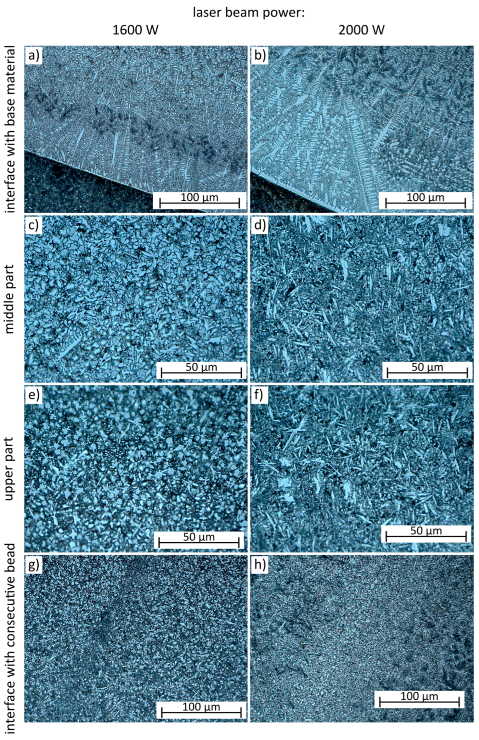
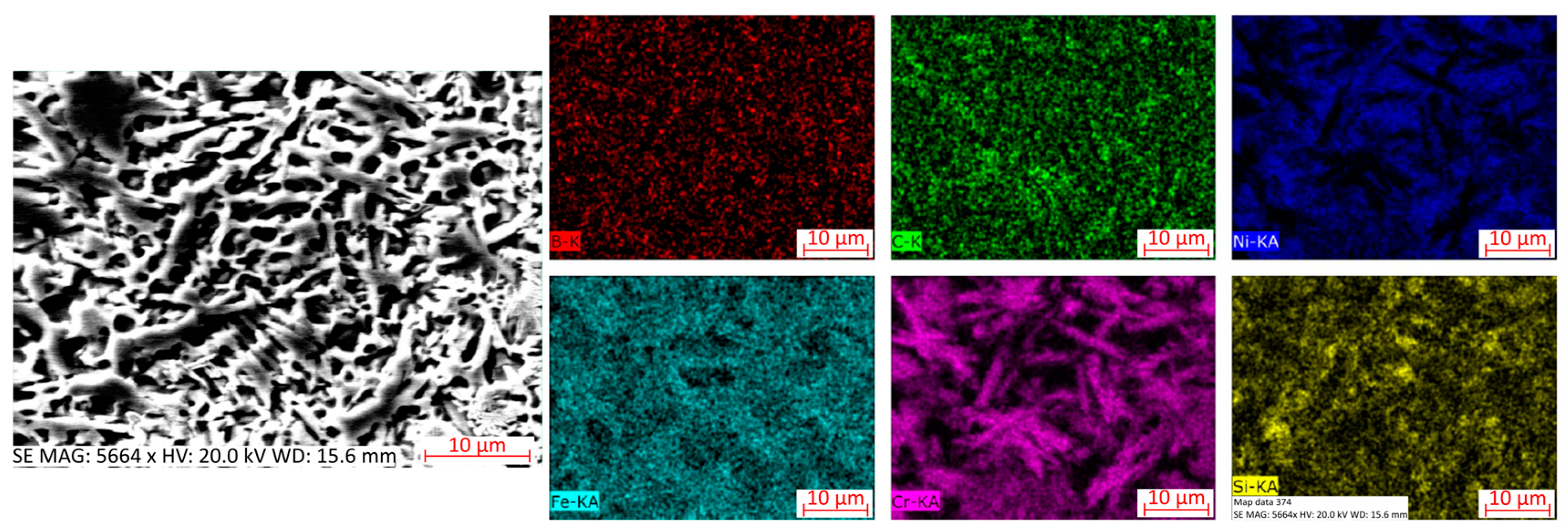
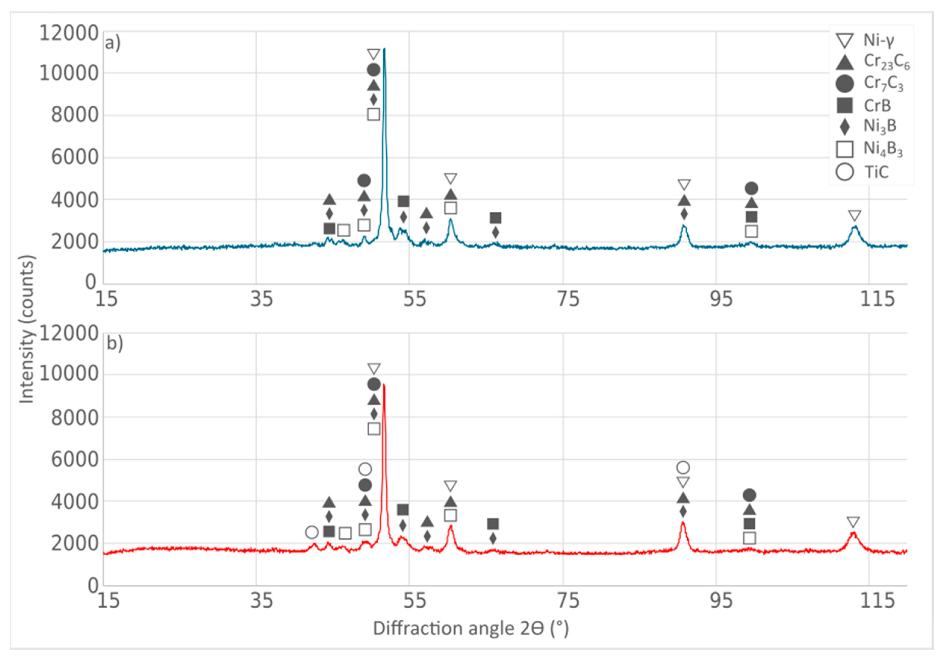
3.3. Microstructure Analysis

The microstructure of laser-cladded NiCrBSi coatings is presented in Figure 3 and the EDS mapping results are presented in Figure 4. The structure of the NiCrBSi coatings is mainly composed of Ni-γ and chromium carbides and borides (Cr23C6, Cr7C3, and CrB) (Figure 5a), which is typical for those alloys and these peaks were also detected and reported previously [33,42,47]. Generally, the microstructure of the analyzed Ni-based coatings is composed of austenite rich in Ni, Si, and Fe and chromium precipitates (carbides and borides) (Figure 4) [29]. Due to the local changes in solidification conditions, the morphologies changed in different areas of the coatings. In general, the grain structure depends on the ratio between the temperature gradient and the solidification rate [48,49]. At the interface of the coating and base material (Figure 3a,b), the smooth transition zone can be seen without defects. The coarse planar and columnar microstructure can be observed close to the interface due to the high temperature gradient and relatively low solidification rate. The columnar crystals grew in a direction consistent with the direction of heat transfer to the base material. As can be observed in Figure 3a,b, the length of the columnar crystals increased with a higher laser beam power, which led to an increased heat input and reduced solidification rate. With the increased distance from the interface with the base material, due to changes in solidification conditions, the morphology of the precipitated phases changed. Furthermore, the increased laser beam power caused the heat input increase and, consequently, impacted the microstructure evolution. In the middle part of the coating processed with a lower laser beam power (Figure 3c), the Ni-γ solid solution and uniformly distributed blocky, equiaxial, and some dendritic precipitates can be seen. In the upper area of this coating, the Ni-γ solid solution and mostly equiaxial and acicular precipitates can be observed (Figure 3e). At the interface between consecutive beads, no grain growth was observed (Figure 3g). In the case of the coating processed with a higher laser beam power in the middle (Figure 3d) and upper areas (Figure 3f), phases show a mostly acicular morphology, with some blocky and equiaxial precipitates. In this case, at the interface between consecutive beads, the grain growth can be seen, which is caused by the subsequent thermal cycle influence.
The microstructures of Ni-based coatings reinforced by TiC particles are presented in Figure 6, Figure 7 and Figure 8 and the EDS mapping is presented in Figure 9 and Figure 10. The phase composition of those coatings is mainly the same as that of the pure NiCrBSi coatings discussed above, with additional peaks for the TiC phase (Figure 5b). As can be observed in Figure 6 and Figure 7, most of the introduced TiC particles dissolved in the liquid metal pool. Due to this, the molten pool was enriched with titanium and carbon. Due to the changed composition of the liquid metal pool and solidification conditions caused by the addition of TiC particles, the coatings’ microstructure changed compared to pure NiCrBSi coatings. In general, TiC is characterized by a lower thermal conductivity and its addition caused the decrease in temperature gradient [30]. As a result, some morphology differences can be observed in comparison to pure Ni-based coatings. At the fusion line, similarly to Ni-based coatings, coarse planar and columnar crystals can be observed, but the length of dendrites decreased with the addition of TiC particles (Figure 6a,b compared to Figure 3a,b), as a result of the lower temperature gradient. The middle and upper parts of the analyzed coatings are composed of the Ni-γ solid solution, acicular, and equiaxial chromium-rich precipitates; blocky and dendritic titanium carbides (which is a typical morphology of the in situ formed TiC [27,50]), and some large ex situ added TiC particles (Figure 6c–f). The EDS mapping results presented in Figure 9 show that the coatings’ matrix is composed of Ni, Fe, and Si. The EDS maps also clearly show the chromium and titanium precipitates having different morphologies (Figure 9). As can be observed in Figure 7, with the higher ratio of added TiC particles, more of the dendritic in situ TiC precipitates were formed, having the larger size.
The TiC particles that did not dissolve in the molten pool are mostly located near the coatings’ surface (Figure 7), due to a lower density than the Ni-based alloy. With the increased ratio of TiC in the used powders, more TiC particles can be observed in the structure and they are located deeper. Similarly, more of the in situ precipitated TiC particle can be observed in the upper part of the coatings than closer to the fusion line. The EDS mapping results showing the composition of the introduced TiC particle are presented in Figure 10.
The previously revealed cracks can be observed on the micrographs (Figure 8). The microscopic observations showed that, in the coatings reinforced by TiC, there were cracks directed both perpendicularly and parallel to the coating surface. In the case of the perpendicular cracks, they ended near the fusion line and did not propagate into the base material. The further optimization of process parameters to reduce defects and shape the microstructure and properties of the coatings should lead to the development of technology suitable for applications in the aerospace, mining, and other industries regarding hard and wear-resistant coatings.

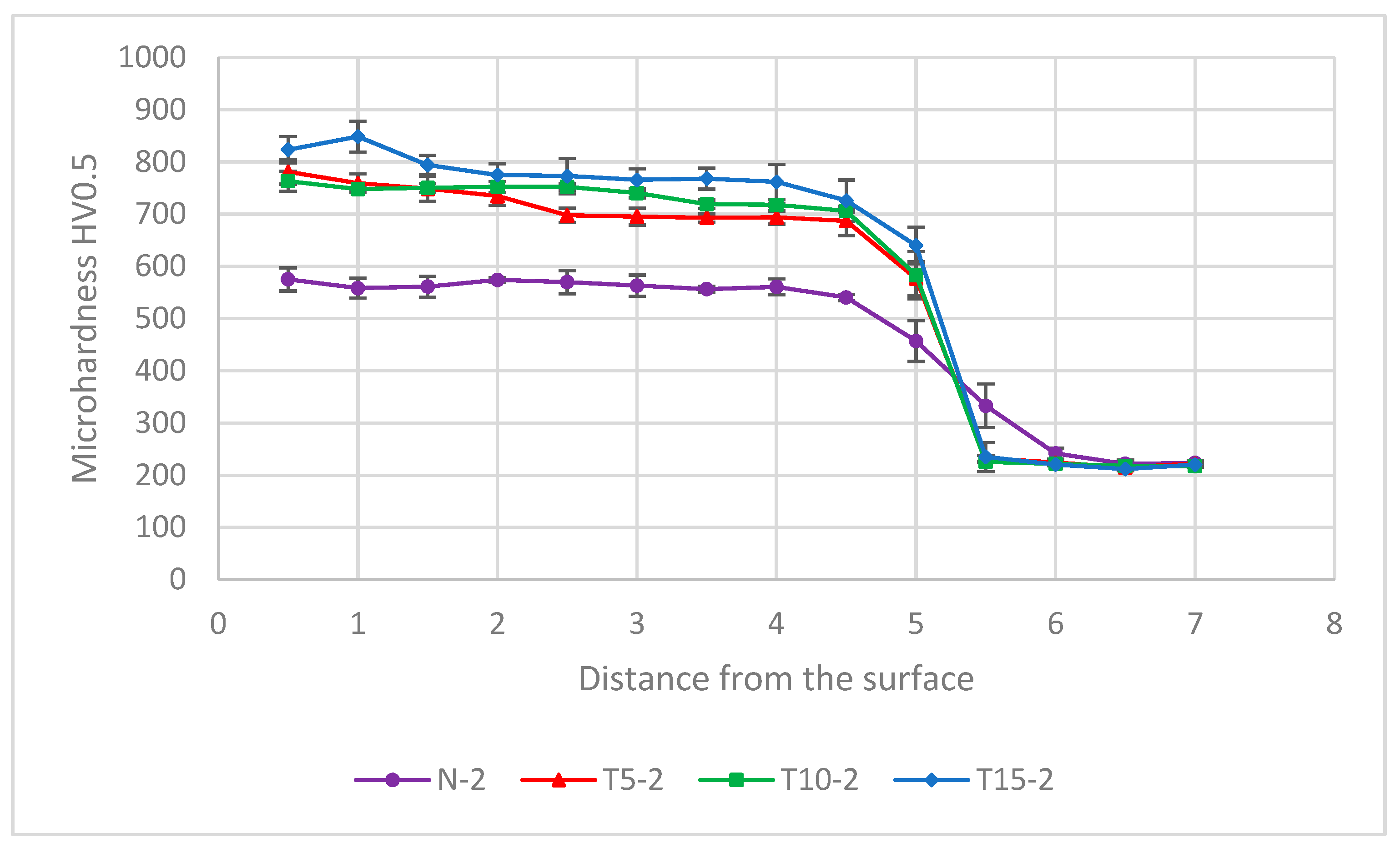
3.4. Microhardness Analysis

The average microhardness results are presented in Table 5 and the microhardness distributions are presented in Figure 11. The laser-cladded NiCrBSi coating’s average hardness was 565 HV0.5, which is consistent with the results reported in the literature [1,30]. The addition of TiC particles had a positive influence on increasing the average hardness of NiCrBSi coatings by about 157–227 HV0.5. Additionally, the increased TiC fraction caused the increase in average hardness of the coatings.
The hardness distribution in the case of all tested coatings is uniform in the clad layer due to the fine-grained microstructure and its high homogeneity. Due to the dilution of the coating material with the substrate, a slight hardness decrease can be seen near the fusion line. The average hardness of the base material is about 225 HV0.5 and no significant changes in hardness were noted in the heat-affected zones.

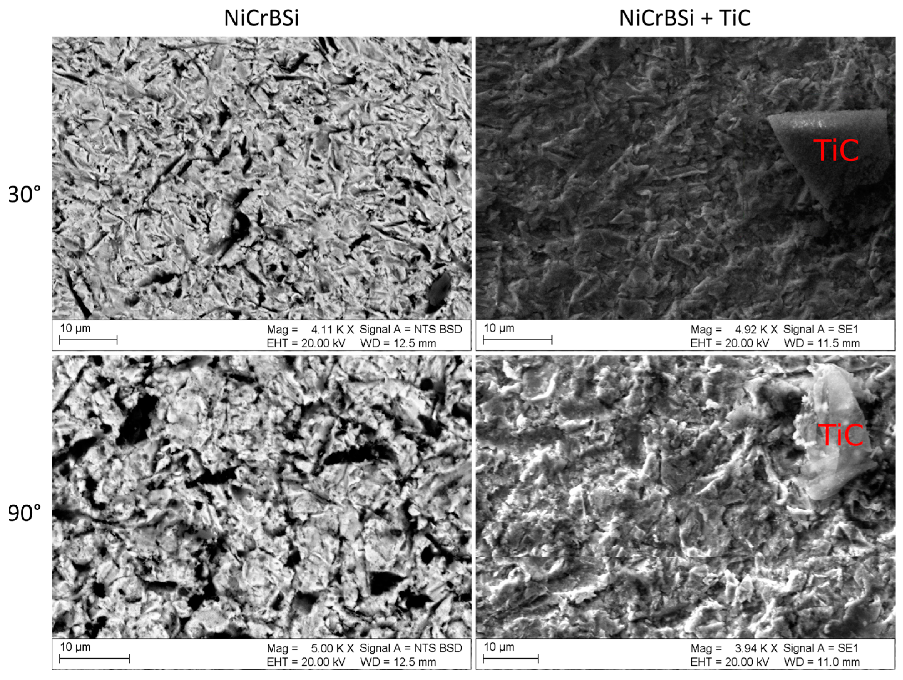
3.5. Erosion Behavior

The average steady-state erosion rates and erosion values are summarized in Table 6. For each of the tested coatings, the erosion values were higher for the impingement angle of 30° than 90°. Such results in general are characteristic of materials showing a ductile mechanism of erosion wear [51]. The solid particle erosion tests revealed that, in the case of a 30° impingement angle, the erosion values and steady-state erosion rates are similar for all of the tested coatings. This means that the TiC particles addition did not significantly improve or reduce the erosion wear resistance in these conditions. For the impingement angle of 90°, there is only a slightly greater variation in the results. In this condition, the lowest erosion value (highest erosion resistance) was noted for the NiCrBSi + 15 wt.% TiC coating, and only a slightly higher result was reported for the pure NiCrBSi coating. For the coatings with added 5 and 10 wt.% of TiC particles, the average erosion values were similar to each other and slightly higher than for the NiCrBSi coating. In general, such a low variation of results shows that the erosion resistance of NiCrBSi coatings with and without added TiC particles is high and similar for each of the tested coatings. In general, erosion is a complex phenomenon and its mechanisms depend on many factors, including the erodent particle material, shape and size, impingement angle, and impact velocity. Additionally, the structure and properties of materials, like the toughness, hardness, and matrix-reinforcing bonding quality, may influence the erosion mechanisms [51]. From previous tests, it was found that the erosion resistance is not entirely hardness-dependent [52]. The microstructure changes and additional precipitation of titanium carbides in NiCrBSi + TiC coatings might influence the erosion mechanism, which resulted in a maintained erosion resistance despite the hardness increase.
To define the erosion wear mechanism, the craters after the solid particle erosion test were observed on the Scanning Electron Microscope (Figure 12). On the micrographs, the plastic deformation of the surfaces subjected to erosion tests can be observed. In general, the surfaces of pure NiCrBSi and TiC-reinforced coatings show similar damage. In the case of the 30° impingement angle, the scars and grooves can be observed, while, for the 90° angle, more craters can be observed. Due to the very fine precipitates sizes, their damage after erosion tests could not be verified. The added TiC particle damage can be observed. Due to the high hardness, it chipped during the impact of the erodent particles. As a ceramic, the titanium carbides show a brittle erosion mechanism, while, for the matrix material and pure Ni-based coatings, the ductile erosion mechanism is confirmed due to the visible deformations of the surface structure. The observations did not show any large losses in the surface caused by the tear of TiC particles during the erosion test, which indicates the good quality of the matrix–particle bonding.

4. Conclusions

The laser cladding process was used to prepare NiCrBSi coatings reinforced with 5–10 wt.% TiC particles. The effect of laser beam power and TiC content on the structure and properties of coatings was tested using penetrant tests, macrostructure and microstructure analysis, and Vickers microhardness and solid particle erosion tests. The analysis of the tests’ results led to the following conclusions:
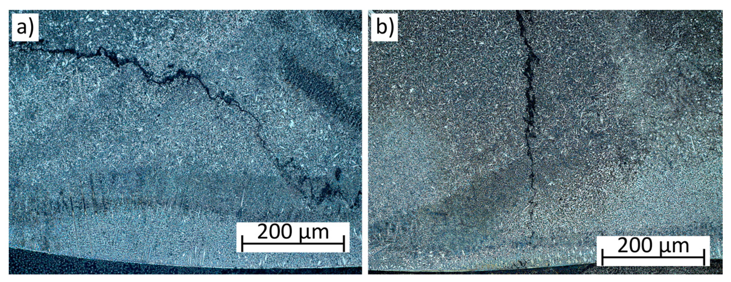
  • The laser cladding process parameters significantly affect the quality of NiCrBSi + TiC coatings. Penetrant tests revealed the cracks’ presence in most of the tested coatings, and a macrostructural analysis revealed the porosity in coatings with added TiC particles, especially those produced using a lower laser beam power. With increased laser beam power, defects such as cracks and porosity can be reduced.
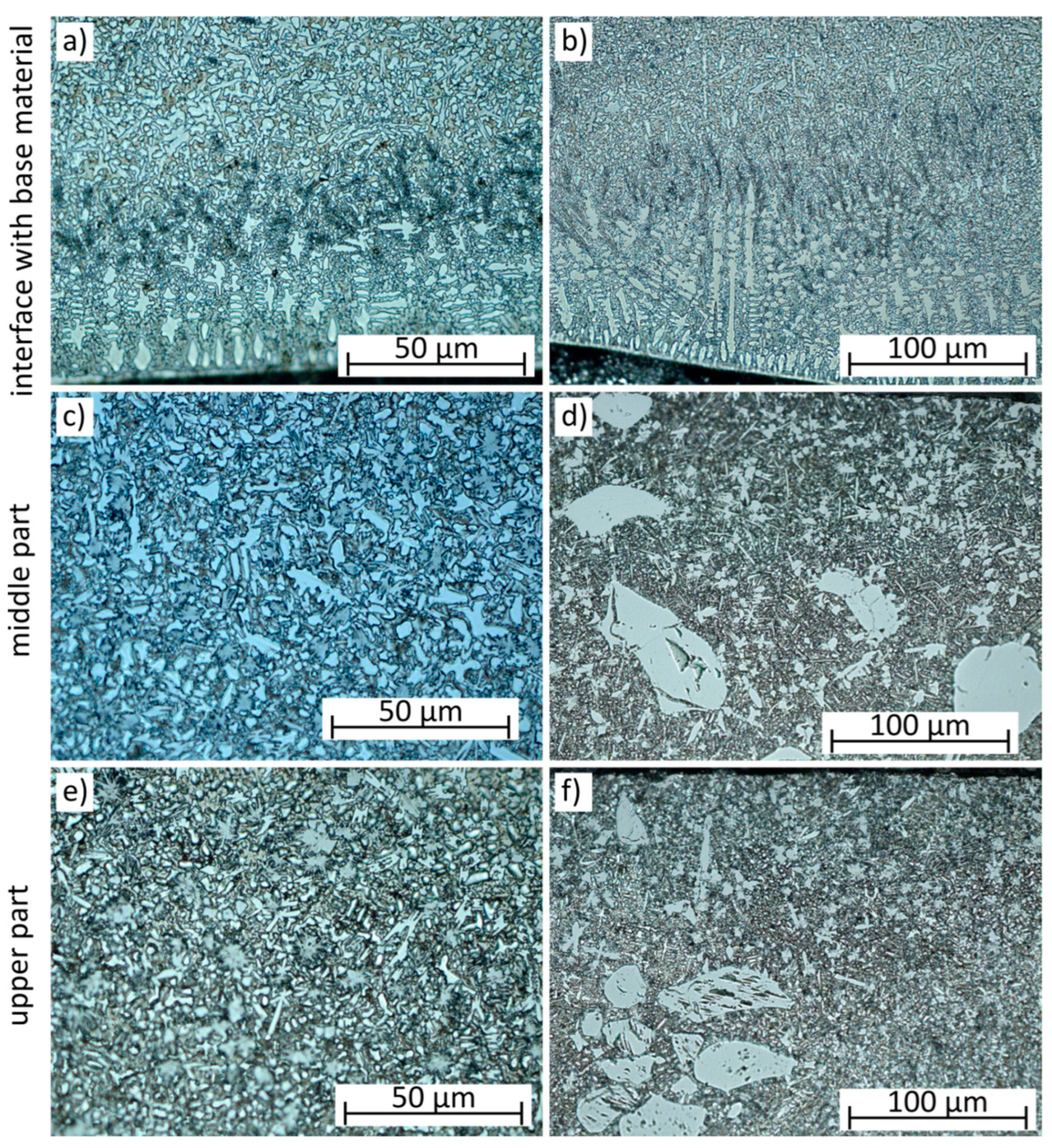
  • The microstructure of NiCrBSi coatings is composed of Ni-γ matrix and fine chromium precipitates, exhibiting different morphologies in the structure (mainly blocky, equiaxial, and acicular), depending on local crystallization conditions.
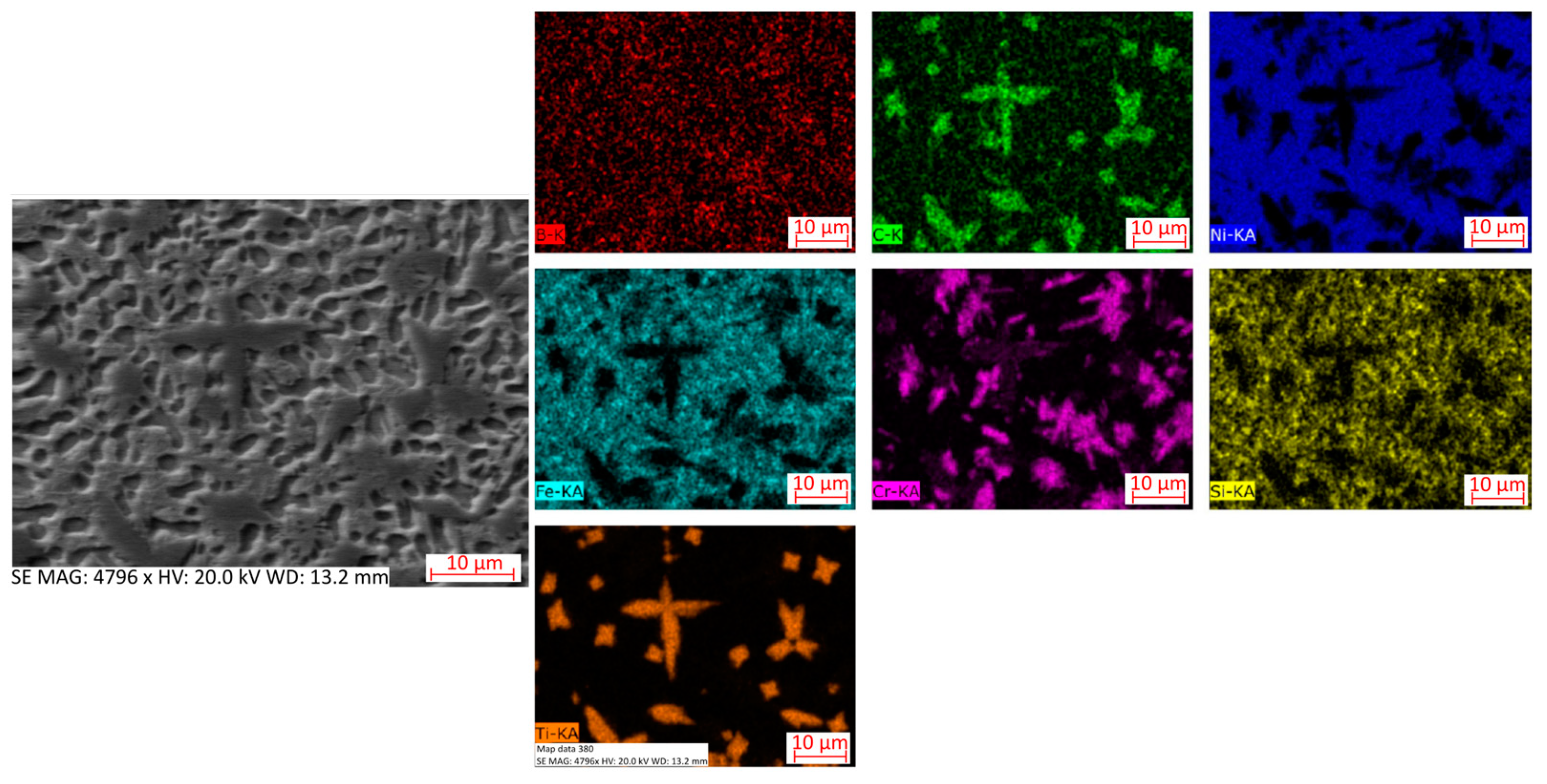
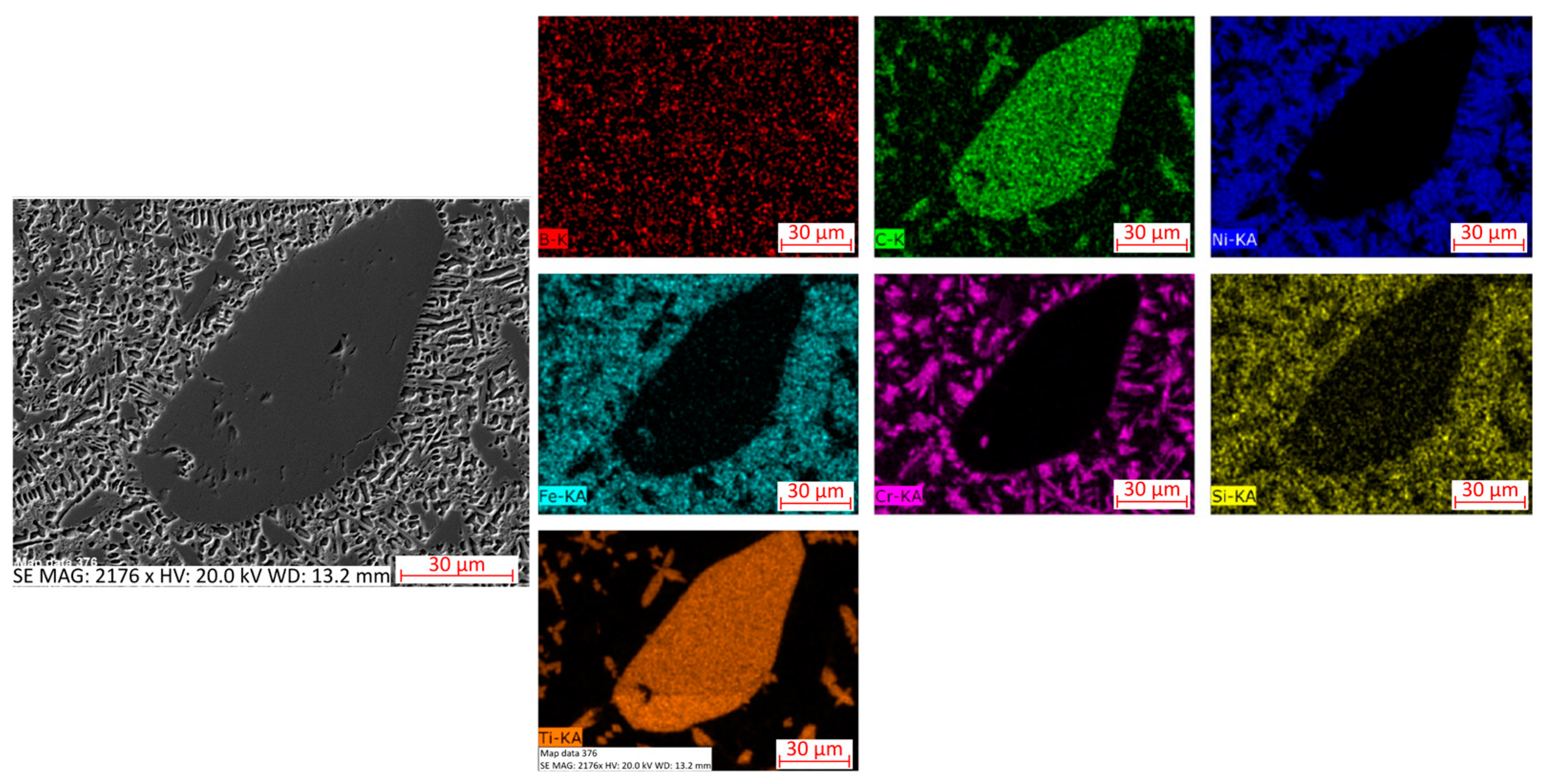
  • The TiC particles added to the NiCrBSi powder partially dissolved in the liquid metal pool during the laser cladding process, leading to an enrichment of the NiCrBSi alloy with titanium and carbon, and the further in situ precipitation of titanium carbides. In the Ni-γ matrix, equiaxial and acicular chromium precipitates were observed, along with blocky and dendritic titanium carbides, and some large TiC particles that did not dissolve, mainly near the coatings surface.
  • The addition of 5–15 wt.% TiC particles to NiCrBSi laser-cladded coatings resulted in an increase in hardness by 28%–40%. Due to the fine and homogeneous microstructure, the hardness was uniform throughout the coatings’ depth.
  • The results of the solid particle erosion tests showed that the addition of TiC particles to the NiCrBSi laser-cladded coatings maintained their erosion resistance. Observations of erosion craters indicated that NiCrBSi coatings exhibited a ductile erosion wear mechanism. In composite coatings with added TiC particles, the matrix showed a ductile mechanism and TiC particles exhibited a brittle mechanism of erosion wear. These findings are valuable for hard and wear-resistant coatings for specific mechanical applications.

Author Contributions

Conceptualization, J.G., A.L. and T.P.; methodology, A.L. and T.P.; software, T.P.; validation, A.L. and J.G.; formal analysis, A.L.; investigation, T.P.; resources, J.G.; data curation, T.P.; writing—original draft preparation, A.L.; writing—review and editing, J.G. and T.P.; supervision, J.G. All authors have read and agreed to the published version of the manuscript.

Funding

This research received no external funding.

Institutional Review Board Statement

Not applicable.

Informed Consent Statement

Not applicable.

Data Availability Statement

Data is contained within the article.

Conflicts of Interest

The authors declare no conflicts of interest.

References

  1. de Sousa, J.M.S.; Ratusznei, F.; Pereira, M.; de Medeiros Castro, R.; Curi, E.I.M. Abrasion resistance of Ni-Cr-B-Si coating deposited by laser cladding process. Tribol. Int. 2020, 143, 106002. [Google Scholar] [CrossRef]
  2. Paulin, C.; Chicet, D.L.; Istrate, B.; Panturu, M.; Munteanu, C. Corrosion behavior aspects of Ni-base self-fluxing coatings. IOP Conf. Ser. Mater. Sci. Eng. 2016, 147, 012034. [Google Scholar] [CrossRef]
  3. Kazamer, N.; Muntean, R.; Valean, P.C.; Pascal, D.T.; Marginean, G.; Serban, V.A. Comparison of Ni-Based Self-Fluxing Remelted Coatings for Wear and Corrosion Applications. Materials 2021, 14, 3293. [Google Scholar] [CrossRef]
  4. Simunovic, K.; Saric, T.; Simunovic, G. Different Approaches to the Investigation and Testing of the Ni-Based Self-Fluxing Alloy Coatings—A Review. Part 1: General Facts, Wear and Corrosion Investigations. Tribol. Trans. 2014, 57, 955–979. [Google Scholar] [CrossRef]
  5. Simunovic, K.; Havrlisan, S.; Saric, T.; Vukelic, D. Modeling and Optimization in Investigating Thermally Sprayed Ni-Based Self-Fluxing Alloy Coatings: A Review. Materials 2020, 13, 4584. [Google Scholar] [CrossRef] [PubMed]
  6. Gunen, A.; Curuk, A. Properties and High-Temperature Wear Behavior of Remelted NiCrBSi Coatings. JOM 2020, 72, 673–683. [Google Scholar] [CrossRef]
  7. Miguel, J.M.; Guilemany, J.M.; Vizcaino, S. Tribological study of NiCrBSi coating obtained by different processes. Tribol. Int. 2003, 36, 181–187. [Google Scholar] [CrossRef]
  8. Dong, X.Y.; Luo, X.T.; Zhang, S.L.; Li, C.J. A Novel Strategy for Depositing Dense Self-fuxing Alloy Coatings with Sufficiently Bonded Splats by One-Step Atmospheric Plasma Spraying. J. Therm. Spray Technol. 2020, 29, 173–184. [Google Scholar] [CrossRef]
  9. Usana-ampaipong, T.; Dumkum, C.; Tuchinda, K.; Tangwarodomnukun, V.; Teeraprawatekul, B.; Qi, H. Surface and Subsurface Characteristics of NiCrBSi Coating with Different WC Amount Prepared by Flame Spray Method. J. Therm. Spray Technol. 2019, 28, 580–590. [Google Scholar] [CrossRef]
  10. Zhou, Y.X.; Zhang, J.; Xing, Z.G.; Wang, H.D.; Lv, Z.L. Microstructure and properties of NiCrBSi coating by plasma cladding on gray cast iron. Surf. Coat. Technol. 2019, 361, 270–279. [Google Scholar] [CrossRef]
  11. Long, H.; Li, T.; Shi, H.; Gui, Y.; Qiu, C. Experimental Study of Laser Cladding Ni-Based Coating Based on Response Surface Method. Coatings 2023, 13, 1216. [Google Scholar] [CrossRef]
  12. Zhu, L.; Xue, P.; Lan, Q.; Meng, G.; Ren, Y.; Yang, Z.; Xu, P.; Liu, Z. Recent research and development status of laser cladding: A review. Opt. Laser Technol. 2021, 138, 106915. [Google Scholar] [CrossRef]
  13. Natarajan, N.; Krishnaraj, V.; Davim, J.P. Metal Matrix Composites: Synthesis, Wear, Characteristics, Machinability Study of MMC Brake Drum; Springer: Berlin/Heidelberg, Germany, 2014. [Google Scholar]
  14. Davoodi, F.; Atapour, M.; Ashrafizadeh, F.; Rikhtehgaran, R. Dry Sliding Wear Characteristics of NiP/TiN Duplex Coated Aluminum Alloy and Wear Analysis Using Response Surface Method. J. Mater. Eng. Perform. 2022, 31, 6360–6372. [Google Scholar] [CrossRef]
  15. Singh, S.; Kumar, S.; Khanna, V. A review on surface modification techniques. Mater. Today Proc. 2023, in press. [Google Scholar] [CrossRef]
  16. Unune, D.R.; Brown, G.R.; Reilly, G.C. Thermal based surface modification techniques for enhancing the corrosion and wear resistance of metallic implants: A review. Vacuum 2022, 203, 111298. [Google Scholar] [CrossRef]
  17. Jonda, E.; Łatka, L.; Pakieła, W. Microstructure and Selected Properties of Cr3C2–NiCr Coatings Obtained by HVOF on Magnesium Alloy Substrates. Materials 2020, 13, 2775. [Google Scholar] [CrossRef]
  18. Appiah, A.N.S.; Bialas, O.; Żuk, M.; Czupryński, A.; Sasu, D.K.; Adamiak, M. Hardfacing of mild steel with wear-resistant Ni-based powders containing tungsten carbide particles using powder plasma transferred arc welding technology. Mater. Sci. Pol. 2022, 40, 42–63. [Google Scholar] [CrossRef]
  19. Karmakar, R.; Maji, P.; Ghosh, S.K. A Review on the Nickel Based Metal Matrix Composite Coating. Met. Mater. Int. 2021, 27, 2134–2145. [Google Scholar] [CrossRef]
  20. Poloczek, T.; Lont, A.; Górka, J. The Structure and Properties of Laser-Cladded Inconel 625/TiC Composite Coatings. Materials 2023, 16, 1265. [Google Scholar] [CrossRef]
  21. Janicki, D. Laser cladding of Inconel 625-based composite coatings reinforced by porous chromium carbide particles. Opt. Laser Technol. 2017, 94, 6–14. [Google Scholar] [CrossRef]
  22. Górka, J.; Poloczek, T.; Janicki, D.; Lont, A.; Topór, S.; Żuk, M.; Rzeźnikiewicz, A. Microstructure and erosion wear of in situ TiC-reinforced Co-Cr-W-C (Stellite 6) laser-cladded coatings. Materials 2024, 17, 3101. [Google Scholar] [CrossRef] [PubMed]
  23. Mi, H.; Chen, T.; Deng, Z.; Li, S.; Liu, J.; Liu, D. Microstructure and Mechanical Properties of TiC/TiB Composite Ceramic Coatings In-Situ Synthesized by Ultrasonic Vibration-Assisted Laser Cladding. Coatings 2022, 12, 99. [Google Scholar] [CrossRef]
  24. Lisiecki, A.; Kurc-Lisiecka, A. Laser Cladding of NiCrBSi/WC + W2C Composite Coatings. Coatings 2023, 13, 576. [Google Scholar] [CrossRef]
  25. Bialas, O.; Appiah, A.N.S.; Wala, M.; Kunwar, A.; Woźniak, A.; Nuckowski, P.M.; Simka, W.; Raback, P.; Adamiak, M. Laser assisted fabrication of mechanochemically robust Ti3Au intermetallic at Au-Ti interface. Eng. Sci. Technol. Int. J. 2023, 42, 101413. [Google Scholar] [CrossRef]
  26. Mhadhbi, M.; Driss, M. Titanium Carbide: Synthesis, Properties and Applications. J. Brill. Eng. 2021, 2, 1–11. [Google Scholar] [CrossRef]
  27. Janicki, D. Microstructure and sliding wear behaviour of in-situ TiC-reinforced composite surface layers fabricated on ductile cast iron by laser alloying. Materials 2018, 11, 75. [Google Scholar] [CrossRef]
  28. Lian, G.; Zhang, H.; Zhang, Y.; Yao, M.; Huang, X.; Chen, C. Computational and Experimental Investigation of Micro-Hardness and Wear Resistance of Ni-Based Alloy and TiC Composite Coating Obtained by Laser Cladding. Materials 2019, 12, 793. [Google Scholar] [CrossRef] [PubMed]
  29. Sun, R.L.; Lei, Y.W.; Niu, W. Laser clad TiC reinforced NiCrBSi composite coatings on Ti–6Al–4V alloy using a CW CO2 laser. Surf. Coat. Technol. 2009, 203, 1395–1399. [Google Scholar] [CrossRef]
  30. Devojno, O.G.; Feldshtein, E.; Kardapolava, M.A.; Lutsko, N.I. On the formation features, microstructure and microhardness of single laser tracks formed by laser cladding of a NiCrBSi self-fluxing alloy. Opt. Lasers Eng. 2018, 106, 32–38. [Google Scholar] [CrossRef]
  31. Chen, L.; Yu, T.; Chen, X.; Zhao, Y.; Guan, C. Process optimization, microstructure and microhardness of coaxial laser cladding TiC reinforced Ni-based composite coatings. Opt. Laser Technol. 2022, 152, 108129. [Google Scholar] [CrossRef]
  32. Meng, Q.; Wang, C.; Liu, T.; Song, Q.; Xue, B.; Ciu, H. Microstructure and performance optimization of laser cladding nano-TiC modified nickel-based alloy coatings. Surf. Coat. Technol. 2024, 479, 130583. [Google Scholar] [CrossRef]
  33. Yang, S.; Liu, W.; Zhong, M.; Wang, Z. TiC reinforced composite coating produced by powder feeding laser cladding. Mater. Lett. 2004, 58, 2958–2962. [Google Scholar] [CrossRef]
  34. Huang, X.; Liu, C.; Zhang, H.; Chen, C.; Lian, G.; Jiang, J.; Feng, M.; Zhou, M. Microstructure Control and Friction Behavior Prediction of Laser Cladding Ni35A+TiC Composite Coatings. Coatings 2020, 10, 774. [Google Scholar] [CrossRef]
  35. Surzhenkov, A.; Goljandin, D.; Traksmaa, R.; Viljus, M.; Talviste, K.; Aruniit, A.; Latokartano, J.; Kulu, P. High Temperature Erosion Wear of Cermet Particles Reinforced Self-Fluxing Alloy HVOF Sprayed Coatings. Mater. Sci. 2015, 21, 386–390. [Google Scholar] [CrossRef]
  36. Katsich, C.; Badisch, E. Effect of carbide degradation in a Ni-based hardfacing under abrasive and combined impact/abrasive conditions. Surf. Coat. Technol. 2011, 206, 1062–1068. [Google Scholar] [CrossRef]
  37. Zikin, A.; Antonov, M.; Hussainova, I.; Katona, L.; Gavrilovic, A. High temperature wear of cermet particle reinforced NiCrBSi hardfacings. Tribol. Int. 2013, 68, 45–55. [Google Scholar] [CrossRef]
  38. Szala, M. Cavitation erosion damage of self-fluxing NiCrSiB hardfacings deposited by oxy-acetylene powder welding. J. Phys. Conf. Ser. 2021, 2130, 012033. [Google Scholar] [CrossRef]
  39. ASTM E407-99; Standard Practice for Microetching Metals and Alloys. ASTM International: West Conshohocken, PA, USA, 1999.
  40. ASTM G76-18; Standard Test Method for Conducting Erosion Tests by Solid Particle Impingement Using Gas Jets. ASTM International: West Conshohocken, PA, USA, 2018.
  41. Sedighi, A.M.; Nabavi, S.F.; Farshidianfar, A.A. A Review on Effect of Cooling Rate on Metallurgical, Mechanical, Geometrical Characteristics and Defects of Laser Cladding Process. Lasers Manuf. Mater. Process 2024, 11, 677–742. [Google Scholar] [CrossRef]
  42. Shi, B.; Li, T.; Wang, D.; Zhang, X.; Zhang, H. Investigation on crack behavior of Ni60A alloy coating produced by coaxial laser cladding. J. Mater. Sci. 2021, 56, 13323–13336. [Google Scholar] [CrossRef]
  43. Simunovic, K.; Saric, T.; Simunovic, G. Different Approaches to the Investigation and Testing of the Ni-Based Self-Fluxing Alloy Coatings—A Review. Part 2: Microstructure, Adhesive Strength, Cracking Behavior, and Residual Stresses Investigations. Tribol. Trans. 2014, 57, 980–1000. [Google Scholar] [CrossRef]
  44. Sun, R.L.; Yang, D.Z.; Guo, L.X.; Dong, S.L. Laser cladding of Ti-6Al-4V alloy with TiC and TiC+NiCrBSi powders. Surf. Coat. Technol. 2001, 135, 307–312. [Google Scholar] [CrossRef]
  45. Zeng, C.; Tian, W.; Liao, W.H.; Hua, L. Microstructure and porosity evaluation in laser-cladding deposited Ni-based coatings. Surf. Coat. Technol. 2016, 294, 122–130. [Google Scholar] [CrossRef]
  46. Janicki, D. Shaping the Structure and Properties of Surface Layers of Ductile Cast Iron by Laser Alloying, 1st ed.; Publishing House of the Silesian University of Technology: Gliwice, Poland, 2018; p. 50. [Google Scholar]
  47. Chen, L.-Y.; Xu, T.; Wang, H.; Sang, P.; Lu, S.; Wang, Z.-X.; Chen, S.; Zhang, L.-C. Phase interaction induced texture in a plasma sprayed-remelted NiCrBSi coating during solidification: An electron backscatter diffraction study. Surf. Coat. Technol. 2019, 358, 467–480. [Google Scholar] [CrossRef]
  48. Hu, G.; Yang, Y.; Qi, K.; Lu, X.; Li, J. Investigation of the Microstructure and Properties of NiCrBSi Coating Obtained by Laser Cladding with Different Process Parameters. Trans. Indian Inst. Met. 2020, 73, 2623–2634. [Google Scholar] [CrossRef]
  49. Navas, C.; Colaco, R.; de Damborenea, J.; Vilar, R. Abrasive wear behaviour of laser clad and flame sprayed-melted NiCrBSi coatings. Surf. Coat. Technol. 2006, 200, 6854–6862. [Google Scholar] [CrossRef]
  50. Górka, J.; Lont, A.; Janicki, D.; Poloczek, T.; Rzeźnikiewicz, A. Comparison of the Erosive Wear Resistance of Ductile Cast Iron Following Laser Surface Melting and Alloying. Coatings 2024, 14, 646. [Google Scholar] [CrossRef]
  51. Stachowiak, G.W.; Batchelor, A.W. Engineering Tribology, 4th ed.; Butterworth-Heinemann: Oxford, UK, 2014; pp. 551–556. [Google Scholar]
  52. Malik, J.; Toor, I.H.; Ahmed, W.H.; Gasem, Z.M.; Habib, M.A.; Ben-Mansour, R.; Badr, H.M. Evaluating the Effect of Hardness on Erosion Characteristics of Aluminum and Steels. J. Mater. Eng. Perform. 2014, 23, 2274–2282. [Google Scholar] [CrossRef]
Figure 1. Coatings surfaces view after penetrant tests: (a) N-1, (b) N-2, (c) T5-1, (d) T5-2, (e) T10-1, (f) T10-2, (g) T15-1, and (h) T15-2 (designations according to Table 3).
Coatings 15 00527 g001
Figure 2. The macrographs of laser-cladded coatings: (a) N-1, (b) N-2, (c) T5-1, (d) T5-2, (e) T10-1, (f) T10-2, (g) T15-1, and (h) T15-2 (designations according to Table 3).
Coatings 15 00527 g002
Figure 3. SEM microstructures of NiCrBSi coatings: (a,c,e,g) N-1 and (b,d,f,h) N-2 (designations according to Table 3).
Coatings 15 00527 g003
Figure 4. EDS mapping of the representative NiCrBSi coating microstructure.
Coatings 15 00527 g004
Figure 5. XRD patterns of coatings: (a) N-2 and (b) T10-2 (designations according to Table 3).
Coatings 15 00527 g005
Figure 6. SEM microstructures of NiCrBSi + TiC coatings: (a) T10-1, (b) T15-2, (c) T5-2, (d) T15-1, (e) T10-1, and (f) T15-2 (designations according to Table 3).
Coatings 15 00527 g006
Figure 7. SEM micrographs showing the TiC particles in the coatings: (a) T10-1 and (b) T15-2 (designations according to Table 3).
Coatings 15 00527 g007
Figure 8. SEM micrographs showing cracks in coatings: (a) T5-1 and (b) T10-1 (designations according to Table 3).
Coatings 15 00527 g008
Figure 9. EDS mappings of the representative NiCrBSi + TiC coating matrix microstructure.
Coatings 15 00527 g009
Figure 10. EDS mappings of the representative NiCrBSi + TiC coating matrix and TiC particle microstructure.
Coatings 15 00527 g010
Figure 11. Microhardness distribution of tested coatings from the surface towards base material (designations according to Table 3).
Coatings 15 00527 g011
Figure 12. SEM micrographs of craters after erosion tests.
Coatings 15 00527 g012
Table 1. The S355JR steel and Metco 15E powder chemical compositions.
Material
Designation
CMnSiPSCrBAlCuNiFe
wt.%
S355JR0.21.50.2–0.5max. 0.04max. 0.04max. 0.3-max. 0.02max. 0.03max. 0.3bal.
Metco 15E0.91-4.0--16.83.42--bal.4.1
Table 2. Technical specifications of TRUMPF Trudisc 3302 laser.
PropertyValue
Wavelength (μm)1.3
Maximum output power (W)3300
Laser beam divergence (mm∙rad)<8.0
Fibre core diameter (μm)200
Collimator focal length (mm)200
Focusing lens focal length (mm)200
Beam spot diameter (μm)200
Fiber length (m)20
Table 3. Laser cladding parameters.
DesignationPowder TiC Content (wt.%)Laser Power (W)Speed (mm/min)Powder Feed Rate (g/min)
N-1016002007
N-2020002007
T5-1516002007
T5-2520002007
T10-11016002007
T10-21020002007
T15-11516002007
T15-21520002007
Table 4. The coatings dilution and thickness results.
Designation 1Dilution
(%)
Thickness
(mm)
N-113.92 ± 3.21.09 ± 0.03
N-222.09 ± 5.11.19 ± 0.05
T5-114.45 ± 2.81.47 ± 0.07
T5-214.81 ± 1.91.7 ± 0.05
T10-112.69 ± 2.31.53 ± 0.06
T10-213.45 ± 3.41.76 ± 0.06
T15-17.55 ± 1.31.56 ± 0.07
T15-210.87 ± 1.81.76 ± 0.08
1 Designation of samples according to Table 3.
Table 5. Average microhardness test results.
Designation 1Average Vickers Microhardness
(HV0.5)
N-2564.8 ± 18.5
T5-2721.9 ± 34.6
T10-2736.6 ± 20.1
T15-2792.0 ± 34.5
1 Designation of samples according to Table 3.
Table 6. Solid particle erosion test results.
Designation 1Average Steady-State Erosion Rate (mg/min)Average Erosion Value
(mm3/g)
30°90°30°90°
N-20.0917 ± 0.020.0417 ± 0.0030.0056 ± 0.00110.0025 ± 0.0002
T5-20.0900 ± 0.040.0517 ± 0.0060.0057 ± 0.00250.0033 ± 0.0004
T10-20.0900 ± 0.020.0483 ± 0.010.0059 ± 0.00130.0031 ± 0.0009
T15-20.0867 ± 0.020.027 ± 0.020.0058 ± 0.00130.0018 ± 0.0013
1 Designation of samples according to Table 3.
Disclaimer/Publisher’s Note: The statements, opinions and data contained in all publications are solely those of the individual author(s) and contributor(s) and not of MDPI and/or the editor(s). MDPI and/or the editor(s) disclaim responsibility for any injury to people or property resulting from any ideas, methods, instructions or products referred to in the content.

