Article

Experimental Study on Impact Resistance of Thermoplastic Fiber–Metal Laminates with Different Layup Sequences

1
School of Mechanical Engineering, Hebei University of Technology, Tianjin 300130, China
2
Key Laboratory of Advanced Intelligent Protective Equipment Technology, Ministry of Education, Tianjin 300401, China
3
Key Laboratory of Hebei Province on Scale-Span Intelligent Equipment Technology, Hebei University of Technology, Tianjin 300401, China
*
Author to whom correspondence should be addressed.
Coatings 2025, 15(4), 443; https://doi.org/10.3390/coatings15040443
Submission received: 12 March 2025 / Revised: 1 April 2025 / Accepted: 2 April 2025 / Published: 8 April 2025
(This article belongs to the Special Issue Microstructure, Mechanical and Tribological Properties of Alloys)

Abstract

:
Thermoplastic fiber–metal hybrid composite laminates exhibit superior high-temperature resistance, fatigue resistance, and impact resistance, leading to their increasingly widespread application in the defense, military, aerospace, and marine engineering sectors. In this paper, the impact resistance of laminates with different layup sequences was compared and analyzed through high-speed impact experiments, the dynamic response and failure mechanisms of laminates were explored, and the influence rules of different factors on the impact resistance of laminates were revealed. The findings indicate that distinct laminate configurations possess varying ballistic limits and failure modes. As the number of aluminum alloy layers increases along the thickness direction of laminates, the ballistic limit decreases progressively. When the aluminum alloy layer is distributed on the back of the laminate, the deformation and delamination degree of the laminate will be reduced, and the ballistic limit of the laminate will be improved. The aluminum alloy sandwich will cause more fiber damage, which is not conducive to the energy dissipation of the laminate. These research outcomes are anticipated to provide a technical foundation for the broader application of thermoplastic fiber–metal hybrid composite laminates.

1. Introduction

Fiber–metal laminates (FMLs) are hybrid composite structural materials formed by stacking high-performance fiber-reinforced composites with metal materials, followed by molding under specified pressure and temperature conditions [1]. FMLs combine the advantages of fiber-reinforced composites and metal materials [2,3,4], exhibiting superior mechanical properties compared to traditional laminates composed solely of fiber-reinforced composites or metal materials. They have high fatigue and impact resistance, making them widely applicable in the aerospace, defense, automotive, and marine engineering fields [5,6]. In the aerospace sector, FMLs meet the complex forming, high-strength, and fatigue resistance requirements of aerospace structures and are extensively used in aircraft [7,8]. During service, they face external impact threats, such as bird strikes and hail [9,10]. In the defense sector, FMLs are primarily used in ballistic protection systems due to their high impact resistance [11,12]. Additionally, FMLs are widely used in structures for energy absorption during vehicle collisions and in ship protection [13,14,15].
The thickness ratio of the constituent materials and the positional distribution of the metal layers in laminates can alter the failure mechanisms of laminates. A rational design of the laminate structure can enhance its impact resistance. Ahmadi et al. [16] conducted impact resistance studies on 2/1 GLARE, determining the optimal thickness ratio between the fiber-reinforced composite layer and the aluminum alloy layer. Yaghoubi et al. [17] studied the high-speed impact response of 2/1-6/5 GLARE beams and found that interfacial debonding, as well as the bending and stretching of the aluminum alloy layer, is the main mechanism for dissipating impact energy. The ballistic limit velocity of GLARE increases parabolically with an increase in the number of metal layers and decreases parabolically with an increase in the metal volume fraction. Li et al. [18] studied the dynamic response of 2/1-4/3 GLARE under foam aluminum projectile impact. They found that with an increase in the number of metal layers, the extent of interlaminar damage and the deflection of the laminate decreased. Additionally, GLARE with a diagonal ply configuration exhibits a similar failure mode to GLARE with an orthogonal ply configuration. Kosedag et al. [19] investigated the influence of the metal volume fraction (MVF) on the ballistic performance of fiber–metal laminates (FMLs). This study revealed that the impact resistance of laminates is enhanced with an increase in the metal volume fraction. For FMLs with the same total thickness of metal layers, the position of the metal layers in the thickness direction significantly affects impact performance. Sharma et al. [20] investigated the impact of the distribution of aluminum alloy layers along the thickness direction of FMLs on their response to low-velocity impact. In their study, four types of laminates with the same metal volume fraction were examined. They found that 2/1 FMLs exhibited a smaller maximum displacement and plastic deformation but the highest peak stress, while 4/3 FMLs achieved the highest maximum displacement and plastic deformation but the lowest peak stress. In terms of damage severity, the 4/3 FMLs experienced the most significant damage, whereas the 2/1 FMLs exhibited the least damage severity, although this difference diminished with increasing impact energy. In terms of high-velocity impact, Sharma et al. [21] employed projectile testing to investigate the influence of aluminum alloy layer distribution in FMLs on their impact response. The experiments indicated that under high-velocity impact, 4/3 FMLs exhibited the highest plastic deformation, consistent with the findings in low-velocity impact scenarios. Compared to drop weight impact, laminates subjected to high-velocity impact from hemispherical projectiles showed similar crack formations on the impact face and rear face but at higher energy levels. At the same impact energy level, the maximum displacement and plastic deformation of all four types of FMLs were lower under high-velocity impact from hemispherical projectiles compared to drop weight impact.
The demand for thermoplastic resin-based FMLs has been rising in the defense and aerospace sectors in recent years due to their excellent high-temperature resistance, fatigue resistance, and impact resistance. Among these, impact resistance is a key advantage of thermoplastic resin-based FMLs and has garnered attention from researchers. However, there is currently limited research on this topic.
The type of metal layer material in thermoplastic resin-based FMLs affects their impact resistance. Abdullah et al. [22] studied the high-speed impact performance of polypropylene-based FMLs composed of different grades of aluminum alloys. This study indicated that laminates composed of 2024-T3 exhibit better impact resistance than those composed of 2024-O. The experimental results suggest that applying low-modulus fiber-reinforced composite layers in FMLs allows the aluminum alloy layers to deform independently. Through the local stretching of the aluminum alloy layers, a significant amount of impact energy can be absorbed.
The thickness ratio of component materials and the positional distribution of metal layers in thermoplastic resin-based FMLs affect the impact response and energy dissipation mechanisms of laminates. Abdullah et al. [23] investigated the high-speed impact performance of polypropylene-based FMLs with different structures and varying component material ratios in 2/1 polypropylene-based FMLs. The 2/1 FMLs composed of thicker polypropylene-based fiber-reinforced composite layers exhibited the highest specific penetration energy. For multilayer FMLs (e.g., 4/3 and 3/2 FMLs), the specific penetration energy remained approximately constant as the number of metal layers increased. Cortes et al. [24] found that FMLs based on carbon fiber-reinforced polyetheretherketone (CF/PEEK) composites with orthogonal layup have higher specific penetration energy compared to those with unidirectional layup. Additionally, FMLs based on glass fiber-reinforced polyetherimide (GF/PEI) composites demonstrated higher specific penetration energy compared to GF/PEI composites alone. Santiago et al. [25,26] conducted an experimental study on the impact loading of self-reinforced polypropylene-based FMLs, testing the dynamic mechanical properties of the relevant materials. Based on the experimental results, they established a finite element model in LS-DYNA. Numerical simulations revealed that placing thicker fiber-reinforced composite layers at the rear of the FMLs and thicker aluminum alloy layers in the middle significantly improved the impact resistance of the laminates. Carrillo et al. [27] investigated the impact resistance performance of polypropylene-based FMLs with different structures. This study found that 3/2 FMLs exhibit higher stiffness, lower delamination extent, and higher energy absorption at the initiation of the first crack and penetration compared to other configurations. Sarasini et al. [28] conducted a comparative study on the impact resistance performance of polypropylene-based BARALL and polypropylene-based GLARE under different structural configurations and temperatures. The experiments showed that polypropylene-based BARALL exhibited the best impact resistance performance under various conditions, particularly in terms of energy absorption at the initiation of the first crack. Additionally, significant delamination occurred at the fiber–metal interface in polypropylene-based BARALL. Nassier et al. [29] conducted a comparative analysis on the impact response of FMLs with varying thicknesses of glass fiber-reinforced polyetheretherketone (GF/PEEK) composites. This study found that increasing the thickness of GF/PEEK in the FMLs resulted in higher peak impact stress values and an enhanced energy absorption of the laminates. Cortes et al. [30] studied the impact resistance performance of polypropylene-based FMLs. This research indicated that polypropylene-based Al/GFPP exhibited better impact resistance than epoxy-based Al/GFRP. Liu et al. [31] tested carbon fiber-reinforced epoxy (CF–epoxy) composites and carbon fiber-reinforced polyetherketone (CF/PEKK) composites using gelatin projectiles at four different energy levels. This study found that at the same impact energy, CF–epoxy exhibited poorer impact resistance and greater impact damage compared to CF/PEEK.
Thermoplastic resin-based FMLs possess excellent impact resistance; however, research on the high-speed impact response and failure mechanisms of thermoplastic resin-based FMLs is still in its early stages. Additionally, there are limited references for the structural design of thermoplastic resin-based FMLs. Further exploration is needed to determine how to design these FMLs reasonably and enhance the impact resistance of the laminates. This paper investigates the impact resistance of novel polyetheretherketone (PEEK)-based fiber–metal laminates, reveals their failure mechanisms, and analyzes the impact performance of laminates with different stacking sequences. The findings aim to provide technical support and reference for future designs of advanced protective structures.

2. Materials and Methods

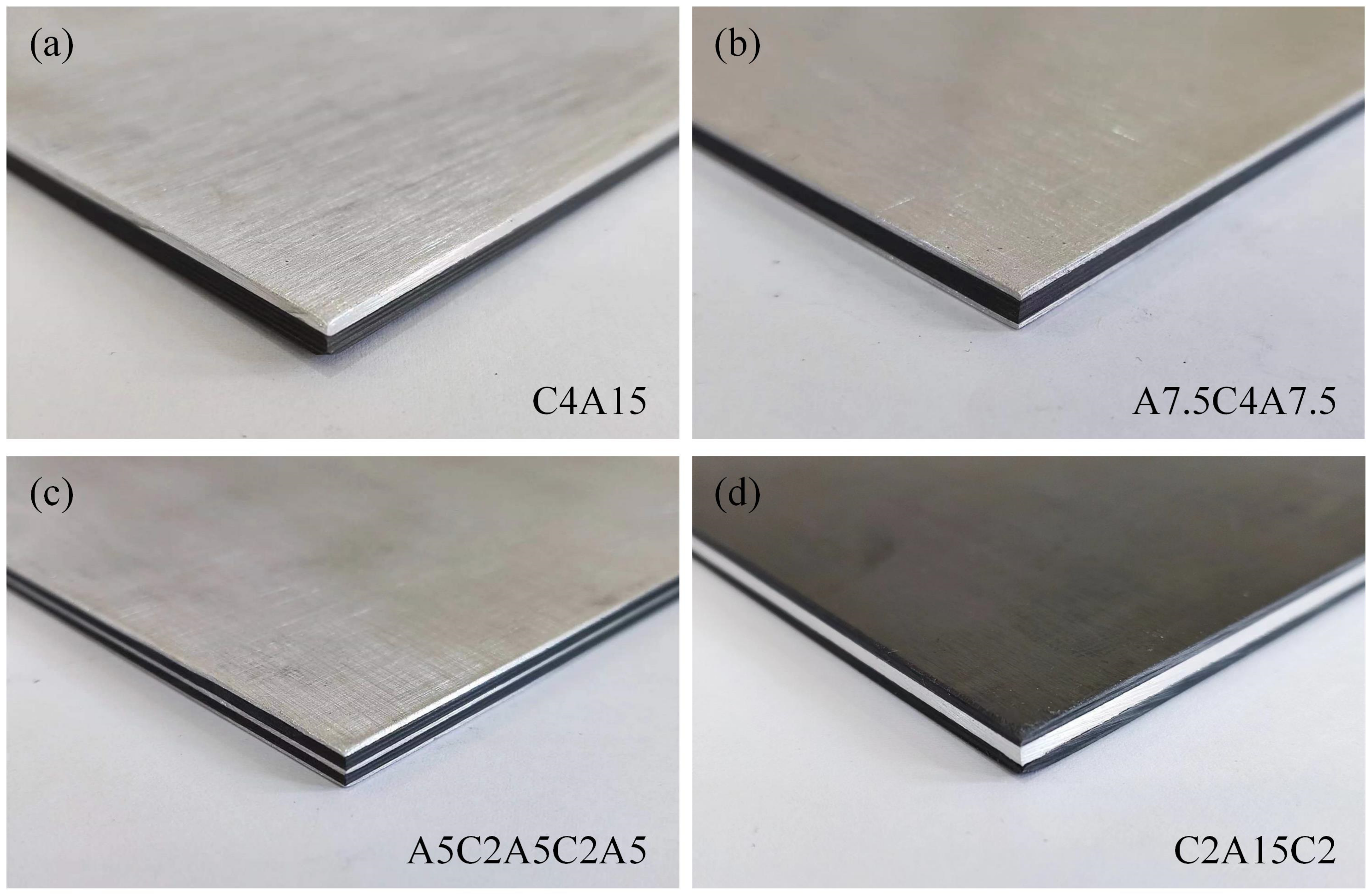
2.1. Specimen Preparation

In this study, four types of carbon fiber–aluminum alloy hybrid composite laminates with equal areal density were designed to investigate the effects of different stacking sequences on their impact response characteristics. The stacking sequences of the laminates are shown in Table 1. The aluminum alloy layers are distributed at various positions along the thickness direction of the laminate while maintaining a constant total thickness of the aluminum alloy layers. The fiber-reinforced composite layers are composed of multiple plies, where [0/90/90/0] represents a single unit. In the nomenclature, ‘C’ denotes a carbon fiber-reinforced composite layer, with the number following ‘C’ indicating the number of units; ‘A’ denotes an aluminum alloy layer, with the number following ‘A’ indicating the thickness of the aluminum alloy layer.
The carbon fiber–aluminum alloy hybrid composite laminates were fabricated using a hot-pressing process. The aluminum alloy used is 2024-T3 (provided by China Southwest Aluminum Co. LTD), with thicknesses of 0.5 mm, 0.75 mm, and 1.5 mm. Before hot-pressing, the aluminum alloy surfaces were roughened by sanding to increase the bonding area between the aluminum alloy layers and the fiber-reinforced composite layers. The fiber-reinforced composite layers are T700-grade carbon fiber-reinforced polyetheretherketone (PEEK) prepregs (provided by China Zhongfu Shenying Carbon Fiber Co., Ltd.), with a single ply thickness of 0.13 mm. A PEEK film with a thickness of 0.1 mm was placed between the aluminum alloy layers and the fiber-reinforced composite layers to enhance interfacial strength. The raw materials were stacked into the designed structure and placed in a hot press. The assembly was heated to 390 °C and held at this temperature for 30 min. Subsequently, a pressure of 2 MPa was applied and maintained for 15 min. Finally, the fabricated laminates were cut into square specimens with dimensions of 120 × 120 mm, shown in Figure 1.

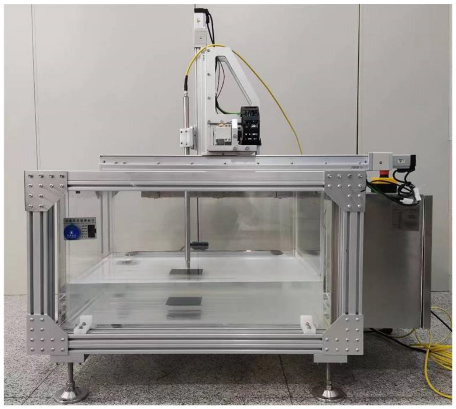
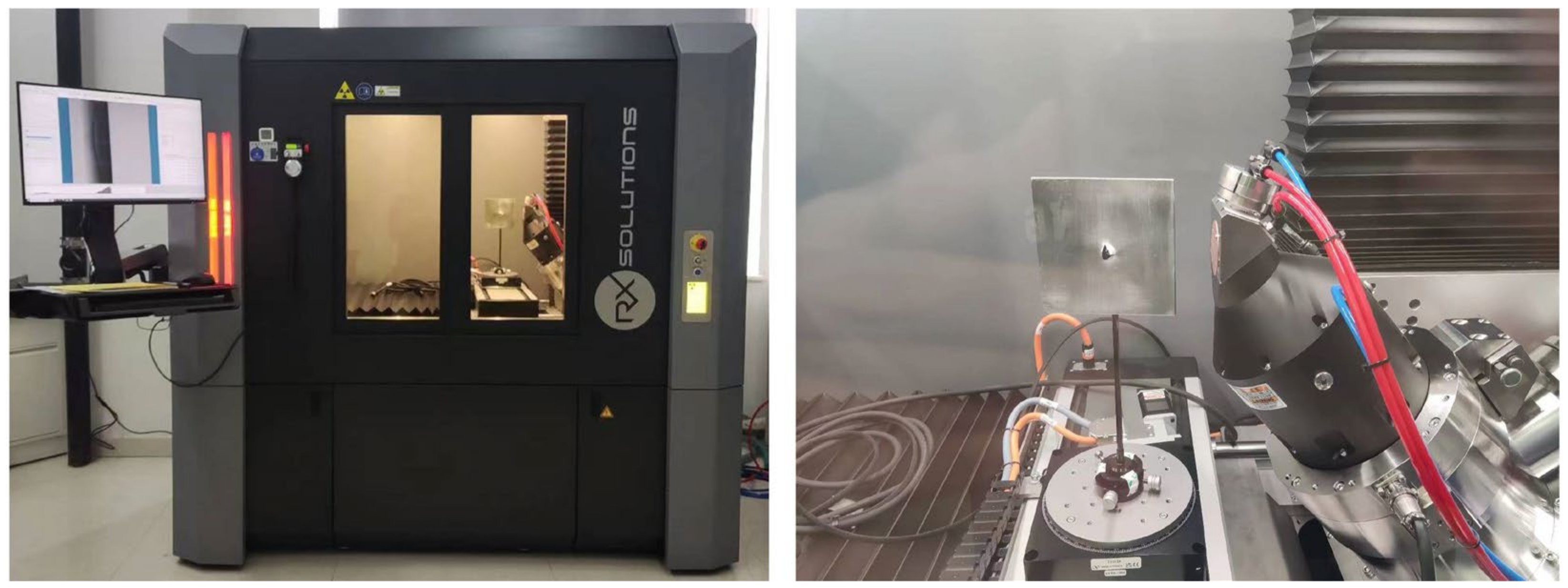
2.2. Experimental Setup

High-velocity impact tests were conducted using a ballistic impact experimental system (provided by Civil Aviation University of China), which consists of a pressurized tank, a propulsion module, a gun barrel, projectiles, a safety chamber, fixtures, and a high-speed camera, as shown in Figure 2. Figure 2a illustrates the gas gun driven by pressurized nitrogen gas. The rapid release of compressed gas in the propulsion module propels the projectile at high speed. The projectile’s velocity is indirectly controlled by adjusting the internal pressure of the propulsion module; therefore, several trial shots are necessary to achieve the target velocity range. The test fixture is placed inside the safety chamber to prevent debris from causing hazards during high-velocity impacts. The laminates are secured using a fixture that applies a fully fixed constraint on all four edges of the specimen. The fixture comprises two parts with a central opening measuring 100 × 100 mm. The specimen is positioned between the two parts and secured at the corners with bolts, as shown in Figure 2b. The projectile used in the tests is a 9.5 mm diameter spherical projectile made of SUJ2 material, as depicted in Figure 2c. A high-speed camera is employed to capture the projectile velocity during the tests and to record the failure modes of the target plates. Figure 2d shows the Photron high-speed camera, equipped with a lighting system, which records the tests at a frame rate of 80,000 frames per second (fps).

3. Results and Discussion

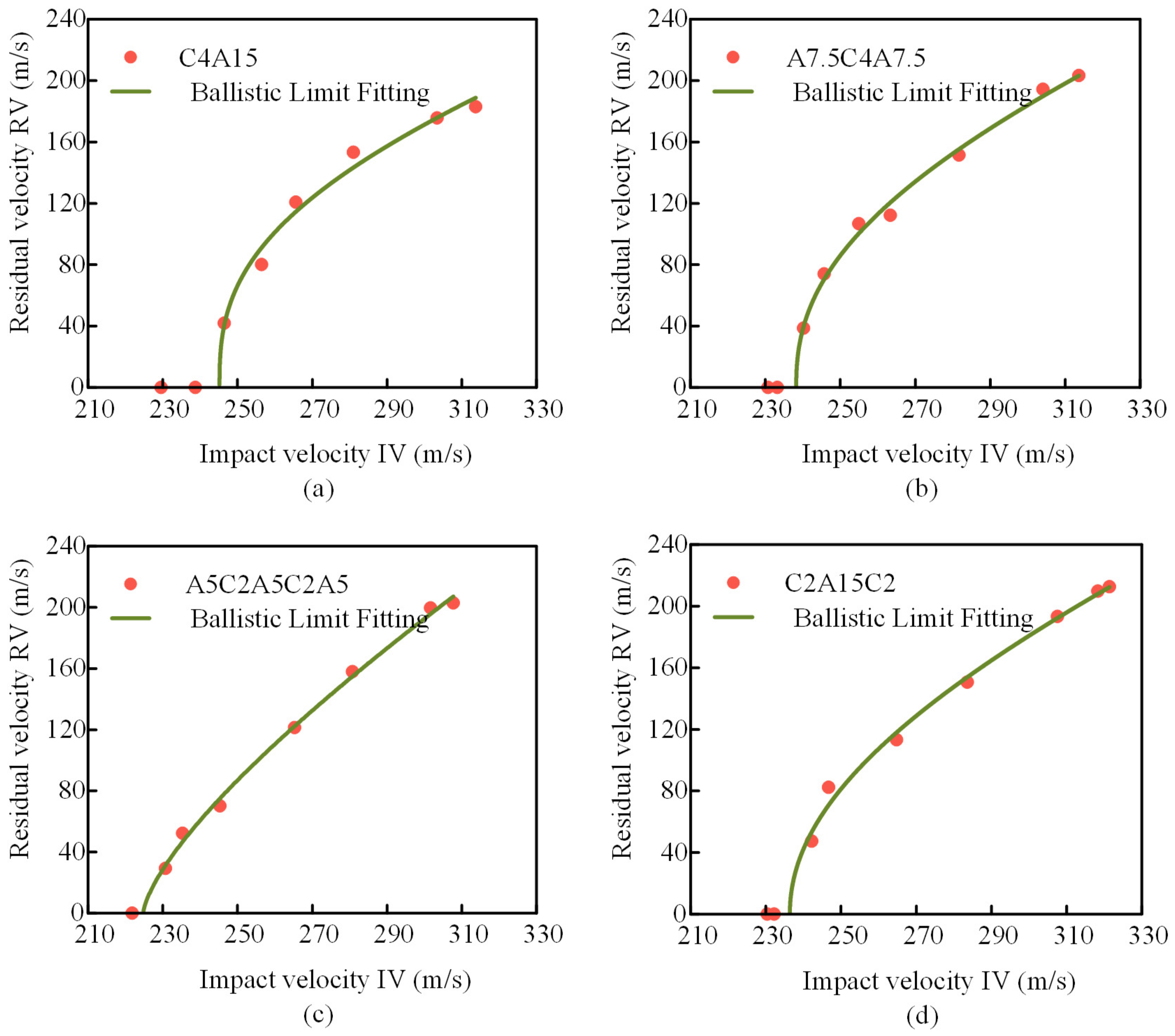
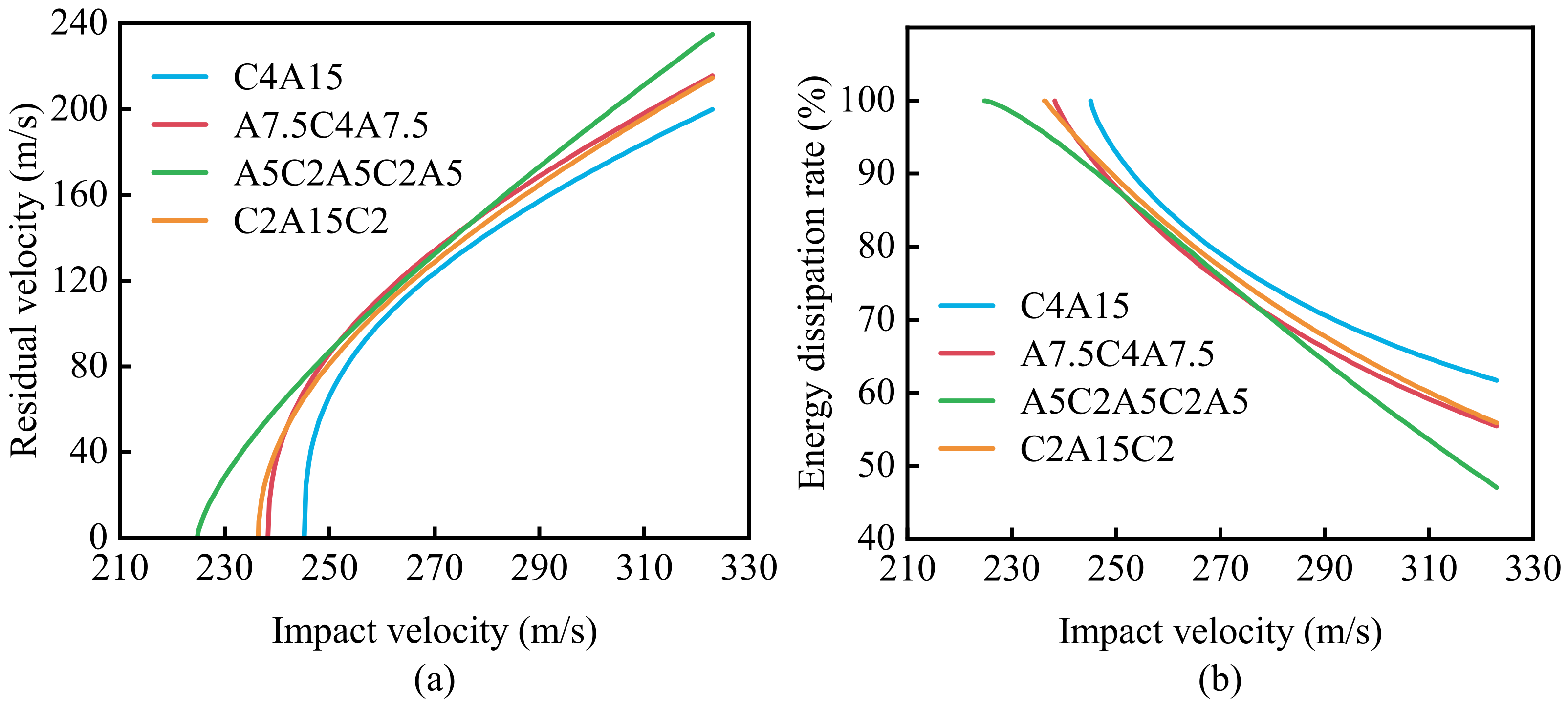
3.1. Ballistic Limit and Energy Dissipation

Each type of laminate with different stacking sequences underwent 8–9 high-velocity impact tests at various speeds. Table 2 lists the experimental data related to the projectile velocities recorded by the high-speed camera. The energy absorption is calculated by subtracting the residual energy from the impact energy. The energy dissipation rate is calculated by dividing the absorbed energy by the impact energy. The equation for calculating energy absorption in the table is as follows:
E a = 1 2 m F v i 2 v r 2
where mF is the mass of the projectile, vi is the impact velocity, and vr is the residual velocity. The equation for calculating the energy dissipation rate is as follows:
Φ = E a E i
where Ea is the total absorbed energy, and Ei is the initial kinetic energy.
The relationship between the initial velocity and the residual velocity of the projectile is fitted using the R-I model [32]. This model, proposed by Recht and Ipson based on extensive experimental research, enables the calculation of the ballistic limit of the target using the initial and residual velocities of the projectile. The model is expressed as follows:
v r = a ( v i b v bl b ) 1 / b
where vr is the residual velocity of the projectile, vi is the initial velocity of the projectile, vbl is the ballistic limit velocity of the target, and a and b are fitting parameters.
The initial velocity–residual velocity relationship curves fitted using Equation (3) for the four different stacking sequences of laminates are shown in Figure 3. The fitting parameters of the equation are listed in Table 3. According to the fitting results, the ballistic limits for C4A15, A7.5C4A7.5, A5C2A5C2A5, and C2A15C2 are 245.2 m/s, 238.2 m/s, 224.7 m/s, and 236.4 m/s, respectively. The highest ballistic limit was observed for C4A15, indicating that it has the best impact resistance under non-penetrating conditions. Conversely, A5C2A5C2A5, which contains the most aluminum layers, achieved the lowest ballistic limit. This suggests that increasing the distribution of aluminum layers along the thickness direction decreases the ballistic limit of the laminate. The ballistic limit of A7.5C4A7.5, and A5C2A5C2A5 decreased by 2.8% and 8.3% compared to C4A15, respectively, showing a trend of a decreasing ballistic limit with an increased distribution of aluminum layers. The ballistic limit of C2A15C2 is lower than that of C4A15, indicating that the same thickness of aluminum layers distributed on the backside of carbon fiber-reinforced composite layers results in the highest ballistic limit.
The residual velocities of projectiles impacting laminates with different stacking sequences show certain differences, as illustrated in Figure 4a. When the initial impact velocity is 270 m/s, the residual velocities after penetrating C4A15, A7.5C4A7.5, A5C2A5C2A5, and C2A15C2 are 123.6 m/s, 134.2 m/s, 135.5 m/s, and 128.5 m/s, respectively. At an initial impact velocity of 320 m/s, the residual velocities are 196.3 m/s, 211.6 m/s, 229.6 m/s, and 210.3 m/s, respectively. It is evident that as the initial velocity of the projectile increases, the residual velocity for C4A15 is lower compared to other stacking sequences, indicating stronger resistance to the projectile. The residual velocity differences among A7.5C4A7.5, C2A15C2, and A5C2A5C2A5 initially decrease to a certain extent and then gradually increase. Figure 4b shows the relationship between initial velocity and energy dissipation rate for the four different stacking sequences. The energy dissipation rate of all four laminates decreases with increasing initial velocity. The decline rate for C4A15, A7.5C4A7.5, and A5C2A5C2A5 gradually slows down, while the decline rate for A5C2A5C2A5 is faster. At the same initial velocity, C4A15 has the highest energy dissipation rate, further demonstrating its superior ability to resist projectile impacts.

3.2. Analysis of Aluminum Alloy Layer Deformation

Under high-velocity impact by projectiles, the aluminum alloy layers in the laminates undergo significant plastic deformation. The plastic deformation of the aluminum alloy layers is a crucial mechanism for dissipating impact kinetic energy. After the high-velocity impact tests, the deformation of the aluminum alloy layers in laminates with different stacking sequences was measured using a dial gauge. The relationship between the deformation of the aluminum alloy layers and the distance from the measurement position to the constrained boundary of the laminate is shown in Figure 5.
Figure 5a–c, respectively, show the deformation of the backside aluminum alloy layers for C4A15, A7.5C4A7.5, and A5C2A5C2A5. It can be observed that as the projectile velocity increases, the slope of the deformation–position relationship gradually increases, indicating that the deformation at the center of the laminate increases. This suggests that when the initial projectile velocity is high, the central area of the laminate experiences greater impact stress, and the laminate is unable to fully dissipate the impact energy, leading to the stress concentration and plastic deformation of the aluminum alloy layers. At an initial projectile velocity of 265 m/s, the positions where the deformation of the backside aluminum alloy layers is 3 mm for C4A15, A7.5C4A7.5, and A5C2A5C2A5 are 38.4 mm, 38.1 mm, and 33.0 mm from the constrained boundary, respectively. At an initial projectile velocity of 300 m/s, these positions are 37.5 mm, 37.5 mm, and 34.1 mm, respectively. This indicates that the position where the deformation of A5C2A5C2A5 is 3 mm is the closest to the constrained boundary, showing greater deformation. However, as the velocity increases, the differences in deformation among these three stacking sequences gradually diminish. Distributing multiple layers of aluminum alloy along the thickness direction of the laminate causes each aluminum alloy layer to bear the load independently, resulting in an increased deformation of the backside aluminum alloy layer. Meanwhile, the deformation of other aluminum alloy layers in the laminate is restricted, which is not conducive to the energy dissipation of the laminate.
Figure 5d shows the deformation of the aluminum alloy interlayer in C2A15C2. Compared to C4A15, the aluminum alloy layer in C2A15C2 is more constrained, resulting in overall smaller deformation. This reduced deformation is not favorable for energy dissipation by the aluminum alloy layer, which explains why the residual velocity of the projectile after penetrating C2A15C2 is generally higher than that for C4A15.

3.3. Analysis of Interlayer Delamination in Composite Laminates

Under high-velocity impact by projectiles, composite laminates are prone to delamination damage. To compare the extent of interlaminar delamination damage in carbon fiber-reinforced composite layers of laminates with different stacking sequences, the aluminum alloy layers of the impacted laminates were manually separated. Subsequently, a water immersion ultrasonic C-scan system was used to scan the carbon fiber-reinforced composite layers in the laminates. The water immersion ultrasonic C-scan system used is the T24 model produced by Physical Acoustics Corporation (PAC) in the USA, with a scanning range of 600 mm by 450 mm and a probe frequency of 10 MHz, as shown in Figure 6.
Some of the results from the ultrasonic C-scan are shown in Figure 7. In this figure, the labels C4A15Ⅰ and A7.5C4A7.5Ⅰ represent the carbon fiber-reinforced composite layers in C4A15 and A7.5C4A7.5, respectively. A5C2A5C2A5Ⅰ and C2A15C2Ⅰ represent the carbon fiber-reinforced composite layers on the projectile-facing side of A5C2A5C2A5 and C2A15C2, respectively. A5C2A5C2A5Ⅱ and C2A15C2Ⅱ represent the carbon fiber-reinforced composite layers on the backside of A5C2A5C2A5 and C2A15C2, respectively. The scan results show the delamination damage as an overlaid projection on a plane, where the deep red and deep blue overlapping areas in the central part indicate the extent of delamination damage. Due to the residual stress from the manufacturing process causing the localized deformation of the laminates, there is some divergence of the sound waves at the specimen edges during scanning. However, this does not affect the extraction of test results.
It can be seen in Figure 7 that when the projectile impact speed is near the ballistic limit, the delamination damage area is larger, but it decreases as the impact speed increases. When the projectile impact speeds are similar, as shown in Figure 7a,b, the delamination damage area of A7.5C4A7.5Ⅰ is larger than that of C4A15Ⅰ. The presence of the aluminum alloy layer on the projectile-facing side of A7.5C4A7.5Ⅰ exacerbates the delamination damage area, and the thinner back aluminum alloy layer of C4A15Ⅰ provides weaker constraints on delamination. Additionally, as shown in Figure 7c,d, the delamination damage areas of A5C2A5C2A5Ⅱ and C2A15C2Ⅱ are significantly larger compared to A5C2A5C2A5Ⅰ and C2A15C2Ⅰ, indicating that the delamination expansion of A5C2A5C2A5Ⅰ and C2A15C2Ⅰ is more strongly restricted.
The extent of delamination damage was assessed by measuring the maximum diameter of the delamination areas using the image digitization tool in Origin on the C-scan images. Measurements were taken without considering the effects of fiber bundle separation on the backside. The obtained maximum delamination diameters are shown in Figure 8. It can be seen from Figure 8 that all laminate configurations achieved the maximum delamination diameter near the ballistic limit, but the changes in the maximum delamination diameter after penetration varied. For C4A15Ⅰ and C2A15C2Ⅰ (in Figure 8a,d), the delamination expansion was significantly constrained by the other layers on the backside, resulting in relatively small changes in the maximum delamination diameter with increasing impact speed. Although A5C2A5C2A5Ⅰ suffered damage to the aluminum alloy layer during impact, the thin aluminum alloy layer and the restriction from other layers resulted in relatively small changes in its maximum delamination diameter with increasing impact speed. In contrast, the maximum delamination diameters of A7.5C4A7.5Ⅰ, A5C2A5C2A5Ⅱ, and C2A15C2Ⅱ (in Figure 8b–d) showed significant changes with increasing impact speed. When the projectile impact speed exceeded the ballistic limit, the maximum delamination diameters of A7.5C4A7.5Ⅰ, A5C2A5C2A5Ⅱ, and C2A15C2Ⅱ experienced a sharp decrease. As the impact speed increased further, the maximum delamination diameters of A7.5C4A7.5Ⅰ and C2A15C2Ⅱ increased slightly before eventually showing a downward trend, while the maximum delamination diameter of A5C2A5C2A5Ⅱ showed little change after the initial sharp decrease.

3.4. Subsection

The damage levels in laminated composites subjected to high-velocity projectile impacts vary depending on the stacking sequence. By observing the failure morphology of the laminates after high-velocity impacts, the failure mechanisms can be analyzed.
Figure 9 shows the impact damage morphology on the front and back surfaces of C4A15 laminates subjected to different projectile velocities. The primary failure modes include fiber debonding, fiber breakage, matrix cracking along the fiber direction, metal plastic deformation, and petal-shaped fractures. From the front surface of the laminates, extensive fiber breakage is observed, which increases with impact velocity. The impact creates a hole in the laminate, approximately equal in diameter to the projectile. The edges of the hole exhibit clean fiber breakage, which becomes more pronounced with higher impact velocities, indicating an increased shearing effect of the projectile on the laminate. On the back surface, at an impact velocity of 238.7 m/s, the metal layer shows a linear crack along the rolling direction. As the impact velocity increases, the aluminum layer develops petal-shaped fractures. At an impact velocity of 281.1 m/s, severe fracturing occurs in the aluminum layer on the back surface, resulting in a peeled-back, petal-shaped fracture with some petals being sheared off.
Figure 10 illustrates the damage morphology on the front and back surfaces of A7.5C4A7.5 laminates subjected to different projectile velocities. The impact results in dents approximately equal in diameter to the projectile. Damage to the aluminum layer on the front surface is primarily localized around the impact hole, exhibiting extrusion fractures and circular bulging. When the projectile velocity is 233.7 m/s, close to the ballistic limit, the laminate is not penetrated, but a small linear crack appears on the back surface of the aluminum layer. At a velocity of 245.7 m/s, the aluminum layer on the back surface exhibits peeled-back, petal-shaped fractures. As the velocity increases to 263.4 m/s, the petals created by the impact start to shear off. At 281.7 m/s, the degree of shearing of the petals increases further.
Figure 11 illustrates the damage morphology of A5C2A5C2A5 laminates on both the impact and rear surfaces after being subjected to various projectile velocities. The impact on the front surface causes extrusion fractures and circular bulging in the aluminum layer, with thin metal sheets forming at the fracture points due to the projectile’s stretching and compressive forces. The rear surface of the laminate exhibits petal-shaped fractures. At a velocity of 265.3 m/s, the aluminum layer shows peeled-back, petal-shaped fractures. When the velocity increases to 280.8 m/s, these fractures become more pronounced.
Figure 12 shows the damage morphology of C2A15C2 laminates on both the impact and rear surfaces after impacts at different velocities. On the impact surface, a significant amount of fiber breakage occurs, forming circular cracks. As the projectile velocity increases, the shearing effect of the projectile on the laminate intensifies, making the circular cracks more pronounced. The outermost fiber layer on the rear surface is pulled out by the projectile, while the next outer layer experiences smooth fiber fractures due to the combined effects of the projectile and the fractured aluminum layer. This exacerbates fiber damage, reducing the laminate’s ability to dissipate energy effectively.
Using micro-CT scanning, the laminated composite panels were scanned after high-speed impact to obtain cross-sectional images. The micro-CT equipment used, as shown in Figure 13, is the EasyTom 230 model manufactured by RX-Solutions, with a radiation source power of 230 kV and a minimum resolution of 2 μm.
Using Avizo software (Version 2022.2), cross-sectional damage images of laminated composite panels were obtained, as shown in Figure 14. It is observed that the panels underwent fiber fractures, matrix cracking, and extensive interlayer delamination, with significant plastic deformation in the aluminum alloy layers. As depicted in Figure 14a,b for C4A15, interlayer delamination increases gradually from the impact face to the back face, accompanied by severe interfacial delamination between the aluminum alloy and composite layers. In Figure 14c,d, A7.5C4A7.5 exhibits pronounced interlayer delamination on both the impact and back faces compared to C4A15. This is attributed to the severe plastic deformation and fracture of the aluminum alloy layer on the impact face under high-speed projectile impact, restricting the recovery of deformation in the composite layers and thereby enhancing delamination. As shown in Figure 14e,f, all three aluminum alloy layers in A5C2A5C2A5 experience fracture, with significant interfacial delamination between the central aluminum alloy layer and the adjacent composite layers, particularly pronounced with the layer below it. In Figure 14g,h, for C2A15C2, the residual deformation and delamination of the composite layer on the impact face are less severe. The central aluminum alloy layer shows reduced overall plastic deformation compared to C4A15, yet substantial delamination is induced in the composite layer on the back face due to its plastic deformation.
Overall analysis reveals that the deformation and delamination of laminates with different stacking sequences depend on the overall bending stiffness of the laminates. Delamination within the laminates results in a reduction in overall bending stiffness, with each layer bearing load independently, thereby increasing structural deformation. For C4A15, all carbon fiber unidirectional layers are stacked together with thicker aluminum alloy layers. During high-speed impact, delamination occurs between the composite layers and aluminum alloy layers, yet the laminate retains higher bending stiffness until failure occurs. In contrast, A5C2A5C2A5 features thinner aluminum alloy layers with more interfaces between the aluminum alloy and composite layers. Consequently, during high-speed impact, greater delamination occurs between the composite layers and aluminum alloy layers, leading to a more significant reduction in overall bending stiffness. This results in a greater plastic deformation of the aluminum alloy layers and a more severe interlayer delamination of the composite layers, as illustrated in Figure 14e.

4. Conclusions

This study conducts experimental research on the impact resistance of four different stacking sequences of laminates, comparing and analyzing their ballistic limits, deformation characteristics, and failure modes. The findings provide insights for the design of laminate stacking.
  • The distribution of aluminum alloy layers along the thickness of the laminate significantly affects the ballistic limit. Specifically, the ballistic limits for C4A15, A7.5C4A7.5, A5C2A5C2A5, and C2A15C2 are 245.2 m/s, 238.2 m/s, 224.7 m/s, and 236.2 m/s, respectively. Increasing the number of layers of aluminum alloy distributed along the thickness direction is detrimental to the laminate’s impact resistance.
  • As the projectile velocity increases, the deformation at the center of the laminate gradually increases. A5C2A5C2A5 exhibits greater deformation, but as velocity increases, the differences in deformation among laminates with different stacking sequences diminish. Multiple layers of aluminum alloy distributed along the thickness independently bear load, thereby increasing laminate deformation.
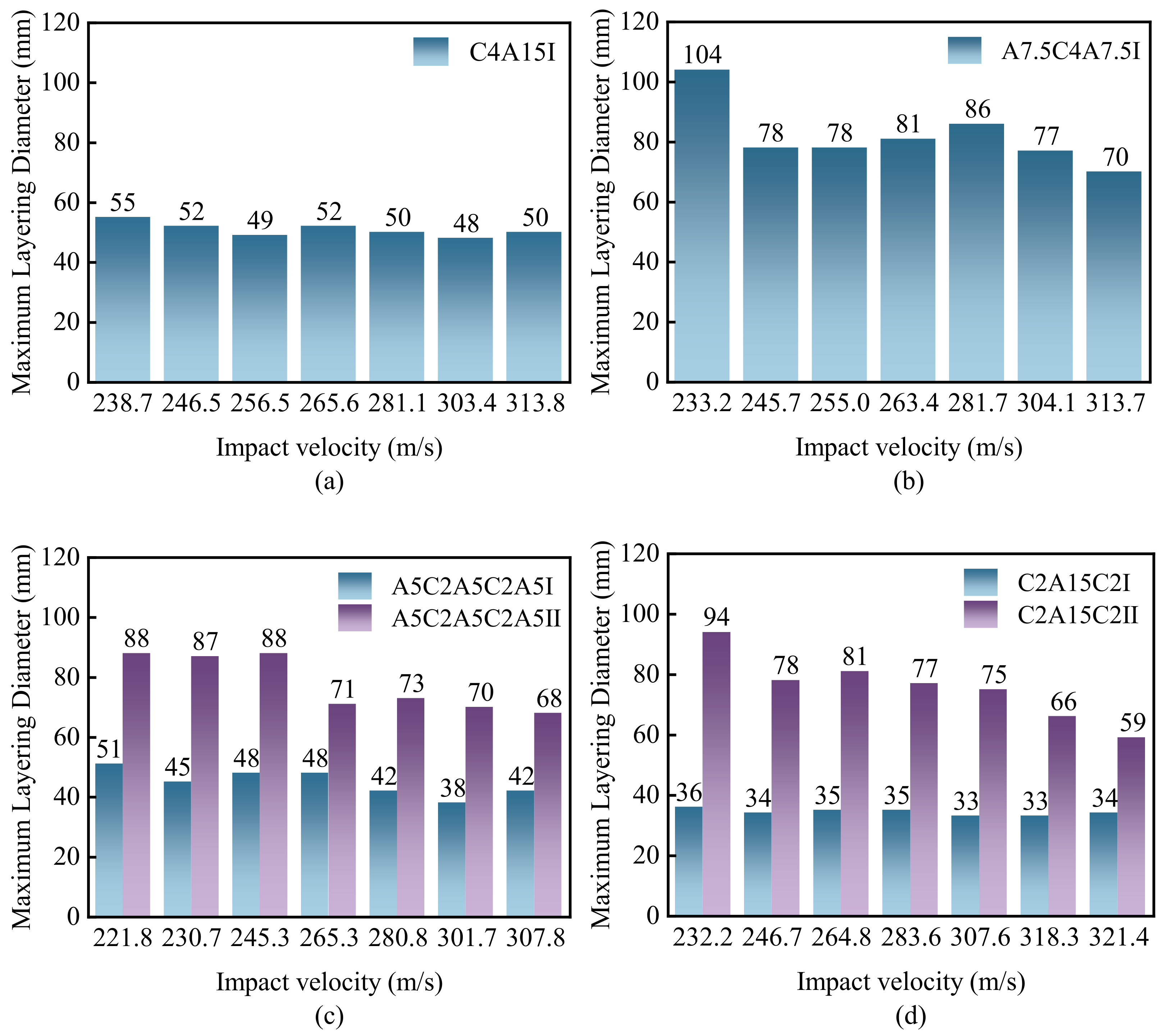
  • The aluminum alloy layer on the impact side exacerbates delamination damage in the fiber-reinforced composite layers, whereas the aluminum alloy layer on the backside limits delamination damage. Laminates of different stacking sequences achieve the maximum delamination diameters near their ballistic limits. When the impact velocity exceeds the ballistic limit, the maximum delamination diameter of the laminate experiences a sudden drop.
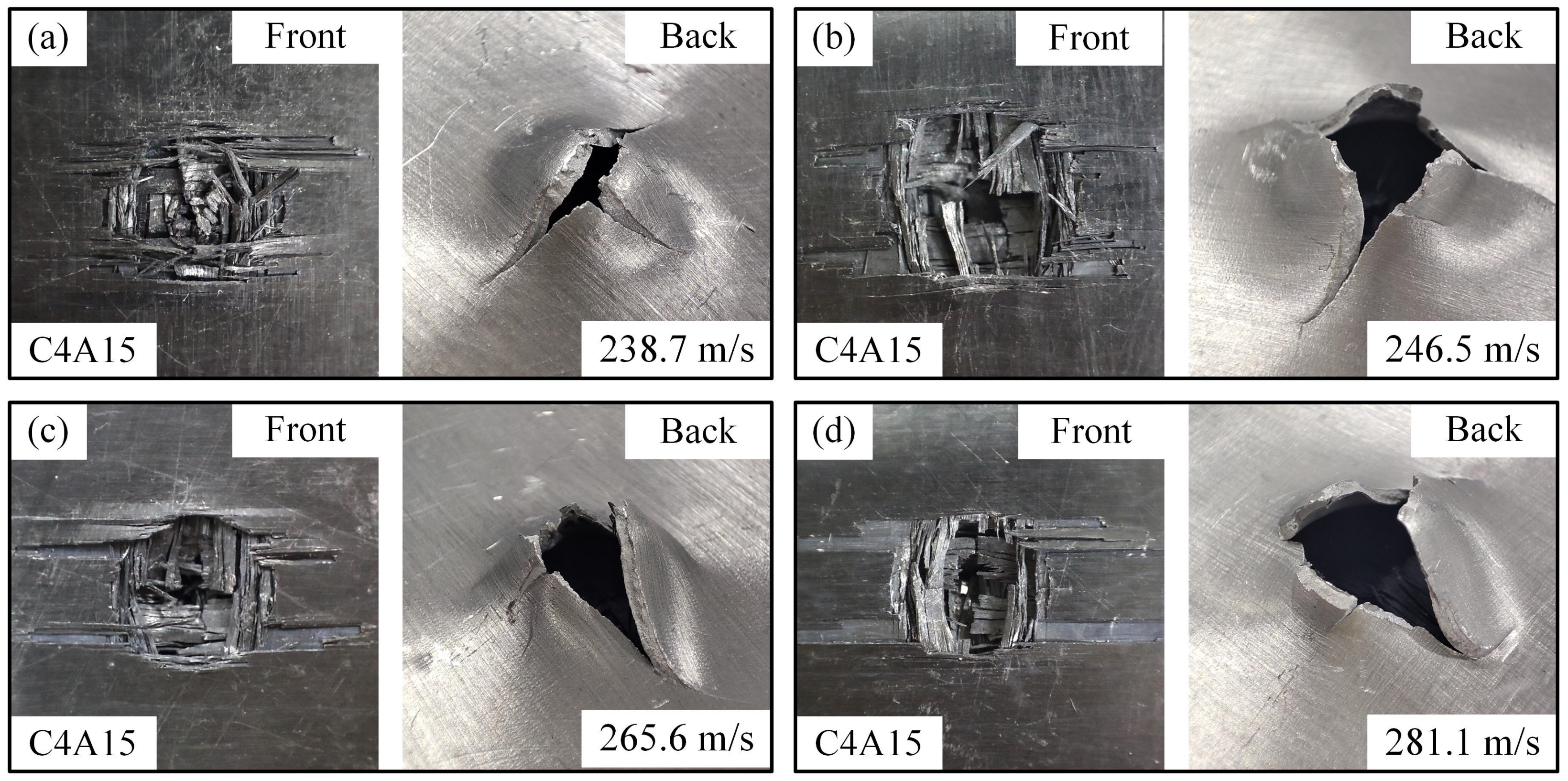
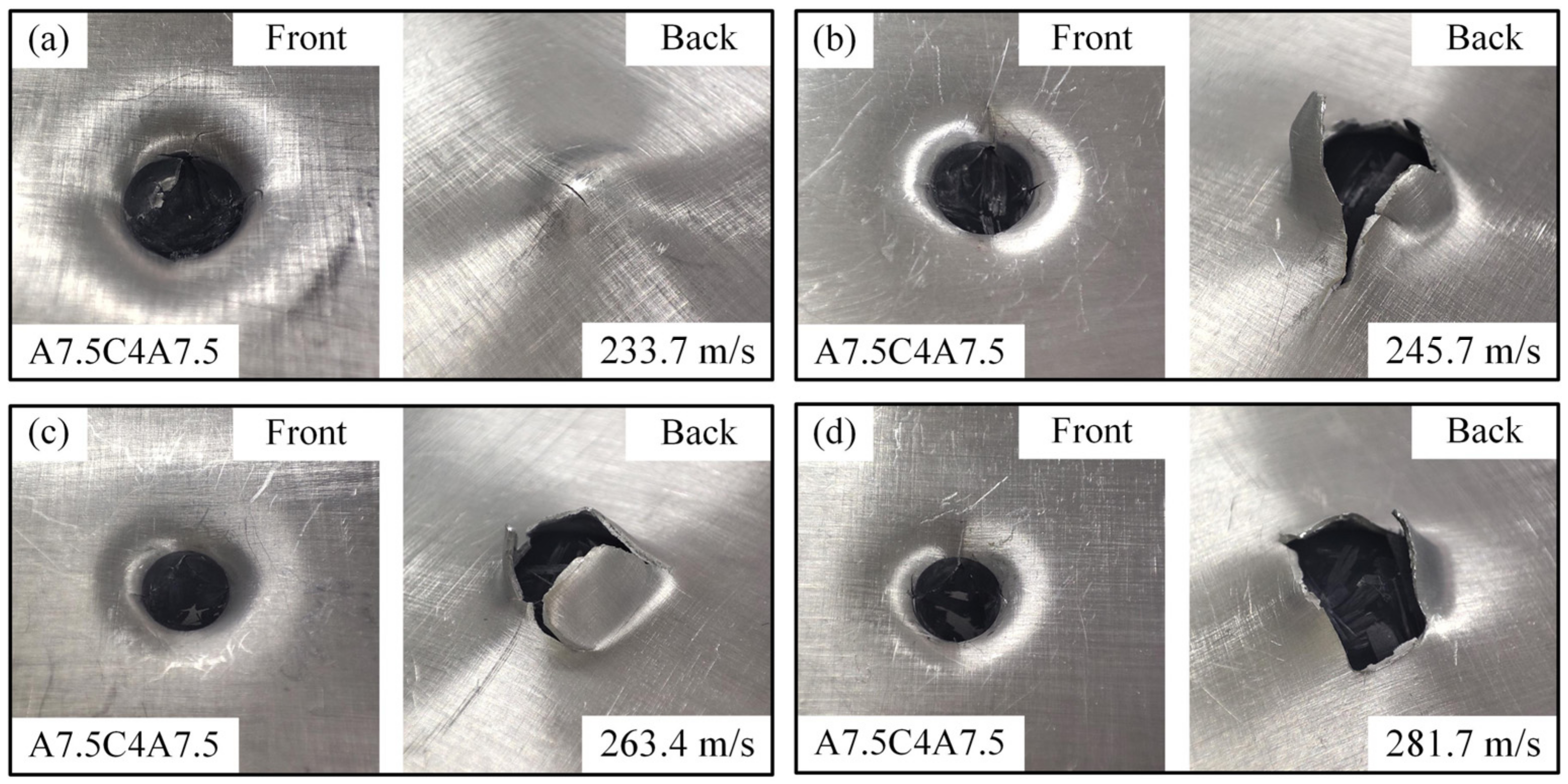
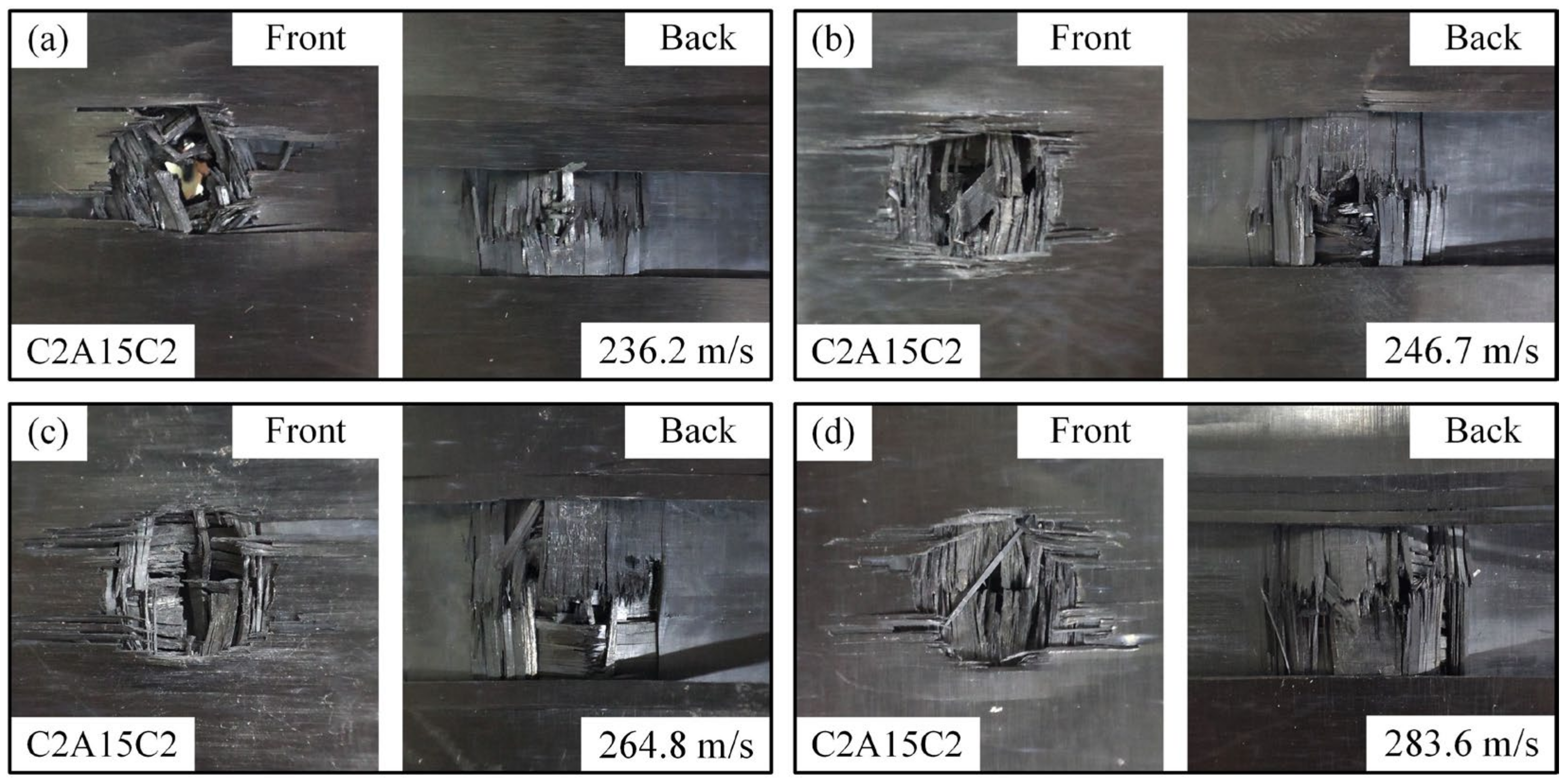
  • The primary failure modes of the laminates include fiber debonding, fiber fracture, matrix cracks along fiber directions, metal plastic deformation, and petal-shaped fractures. With increasing projectile velocity, shear effects from the projectile intensify, causing circular perforations in the carbon fiber-reinforced composite layers and gradually inducing peeling petal-shaped fractures in the aluminum alloy layers.

Author Contributions

Conceptualization, Z.Z. and L.Z.; methodology, Y.L.; validation, Z.Z. and H.G.; investigation, Y.L.; data curation, H.G.; writing—original draft preparation, Y.L. and H.G.; writing—review and editing, Z.Z.; supervision, project administration, and funding acquisition, Z.Z. and L.Z. All authors have read and agreed to the published version of the manuscript.

Funding

This research was funded by National Natural Science Foundation of China (12402161, U23A2067); Science and Technology Project of Hebei Education Department (BJK2023100).

Institutional Review Board Statement

Not applicable.

Informed Consent Statement

Not applicable.

Data Availability Statement

Relevant data supporting the key findings of this study are available in the article. All raw data generated in this study are available from the corresponding author upon reasonable request.

Conflicts of Interest

The authors declare no conflicts of interest.

References

  1. Hu, Y.; Zhou, J.; Ji, F.; Zhang, Y.; Duan, Y.; Guan, Z.; Tao, J. Optimization of preparation technology on fibre metal laminates (FMLs) for high-temperature applications. Int. J. Light. Mater. Manuf. 2020, 3, 317–327. [Google Scholar] [CrossRef]
  2. Sinmazçelik, T.; Avcu, E.; Bora, M.Ö.; Çoban, O. A review: Fibre metal laminates, background, bonding types and applied test methods. Mater. Des. 2011, 32, 3671–3685. [Google Scholar]
  3. Vogelesang, L.B.; Vlot, A. Development of fibre metal laminates for advanced aerospace structures. J. Mater. Process. Technol 2000, 103, 1–5. [Google Scholar]
  4. Şimşir, E. Study of Impact Behavior of Glass-Fiber-Reinforced Aluminum Composite Sandwich Panels at Constant Energy Levels. Coatings 2025, 15, 299–312. [Google Scholar] [CrossRef]
  5. He, W.; Wang, L.; Liu, H.; Wang, C.; Yao, L.; Li, Q.; Sun, G. On impact behavior of fiber metal laminate (FML) structures: A state-of-the-art review. Thin-Walled Struct. 2021, 167, 108026. [Google Scholar]
  6. Serubibi, A.; Hazell, P.J.; Escobedo, J.P.; Wang, H.; Oromiehie, E.; Prusty, G.B.; Phillips, A.W.; St John, N.A. Fibre-metal laminate structures: High-velocity impact, penetration, and blast loading—A review. Compos. Part A 2023, 173, 107674. [Google Scholar] [CrossRef]
  7. Wang, W.; Rans, C.; Benedictus, R. Analytical prediction model for non-symmetric fatigue crack growth in Fibre Metal Laminates. Int. J. Fatigue 2017, 103, 546–556. [Google Scholar]
  8. Ding, Z.; Wang, H.; Luo, J.; Li, N. A review on forming technologies of fibre metal laminates. Int. J. Light. Mater. Manuf. 2021, 4, 110–126. [Google Scholar]
  9. Zhang, F.; Luo, G.; Zhang, H.; Cong, P.; Liu, L.; Chen, W. Experimental and numerical analysis study on the low and medium speed bird strike. Eng. Fail. Anal. 2024, 156, 107766. [Google Scholar]
  10. Rekatsinas, C.S.; Siorikis, D.K.; Nastos, C.V.; Chrysochoidis, N.A.; Theodosiou, T.C.; Yigit, A.S.; Christoforou, A.P.; Saravanos, D.A. An efficient computational framework for hailstone impacts on composite plates utilizing a semi-empirical viscoplastic contact law. Int. J. Impact Eng. 2023, 178, 110–126. [Google Scholar]
  11. Sun, J.; Xu, S.; Lu, G.; Wang, Q.; Gong, A. Ballistic impact experiments of titanium-based carbon-fibre/epoxy laminates. Thin-Walled Struct. 2022, 179, 109709. [Google Scholar]
  12. Corderley, G.; Mostert, F.; Krüger, J.J. Failure modes in a carbon / titanium fibre metal laminate under hyper-velocity impact. Int. J. Impact Eng. 2019, 125, 180–187. [Google Scholar] [CrossRef]
  13. Zhu, Z.; Li, X.; Yang, R.; Xie, W.; Zhang, D. The energy dissipation mechanism of bi-metal Kevlar\titanium fiber metal laminate under high-velocity impact. Eur. J. Mech. A Solids 2023, 100, 104956. [Google Scholar]
  14. Ali, A.; Pan, L.; Duan, L.; Zheng, Z.; Sapkota, B. Characterization of seawater hygrothermal conditioning effects on the properties of titanium-based fiber-metal laminates for marine applications. Compos. Struct. 2016, 158, 199–207. [Google Scholar]
  15. Song, Z.; Ming, S.; Du, K.; Zhou, C.; Wang, Y.; Xu, S.; Wang, B. Energy absorption of metal-composite hybrid tubes with a diamond origami pattern. Thin-Walled Struct. 2022, 180, 109824. [Google Scholar]
  16. Ahmadi, H.; Liaghat, G.H.; Sabouri, H.; Bidkhouri, E. Investigation on the high velocity impact properties of glass-reinforced fiber metal laminates. J. Compos. Mater. 2012, 47, 1605–1615. [Google Scholar] [CrossRef]
  17. Seyed Yaghoubi, A.; Liaw, B. Thickness influence on ballistic impact behaviors of GLARE 5 fiber-metal laminated beams: Experimental and numerical studies. Compos. Struct. 2012, 94, 2585–2598. [Google Scholar]
  18. Li, K.; Qin, Q.; Cui, T.; Han, Q.; Peng, J.; Sha, Z.; Zhang, W. Soft impact of GLARE fiber metal laminates. Int. J. Impact Eng. 2023, 178, 104607. [Google Scholar]
  19. Kosedag, E.; Aydin, M.; Ekici, R. Effect of stacking sequence and metal volume fraction on the ballistic impact behaviors of ARALL fiber-metal laminates: An experimental study. Polym. Compos. 2021, 43, 1536–1545. [Google Scholar]
  20. Sharma, A.P.; Khan, S.H.; Kitey, R.; Parameswaran, V. Effect of through thickness metal layer distribution on the low velocity impact response of fiber metal laminates. Polym. Test. 2018, 65, 301–312. [Google Scholar] [CrossRef]
  21. Sharma, A.P.; Khan, S.H. Influence of metal layer distribution on the projectiles impact response of glass fiber reinforced aluminum laminates. Polym. Test. 2018, 70, 320–347. [Google Scholar]
  22. Abdullah, M.; Cantwell, W. The impact resistance of polypropylene-based fibre–metal laminates. Compos. Sci. Technol. 2006, 66, 1682–1693. [Google Scholar]
  23. Abdullah, M.R.; Cantwell, W.J. The high-velocity impact response of thermoplastic–matrix fibre–metal laminates. J. Strain Anal. Eng. Des. 2012, 47, 432–443. [Google Scholar]
  24. Cortés, P.; Cantwell, W.J. The Impact Properties of High-temperature Fiber-Metal Laminates. J. Compos. Mater. 2007, 41, 613–632. [Google Scholar]
  25. Santiago, R.; Cantwell, W.; Alves, M. Impact on thermoplastic fibre-metal laminates: Experimental observations. Compos. Struct. 2017, 159, 800–817. [Google Scholar]
  26. Santiago, R.C.; Cantwell, W.J.; Jones, N.; Alves, M. The modelling of impact loading on thermoplastic fibre-metal laminates. Compos. Struct. 2018, 189, 228–238. [Google Scholar] [CrossRef]
  27. Carrillo, J.G.; Gonzalez-Canche, N.G.; Flores-Johnson, E.A.; Cortes, P. Low velocity impact response of fibre metal laminates based on aramid fibre reinforced polypropylene. Compos. Struct. 2019, 220, 708–716. [Google Scholar] [CrossRef]
  28. Sarasini, F.; Tirillò, J.; Ferrante, L.; Sergi, C.; Sbardella, F.; Russo, P.; Simeoli, G.; Mellier, D.; Calzolari, A. Effect of temperature and fiber type on impact behavior of thermoplastic fiber metal laminates. Compos. Struct. 2019, 223, 110961. [Google Scholar]
  29. Nassir, N.A.; Birch, R.S.; Cantwell, W.J.; Guan, Z.W. The influence of composite core thickness on the perforation resistance of titanium-based FMLs. Results Mater. 2023, 19, 100414. [Google Scholar]
  30. Cortés, P.; Cantwell, W.J. The fracture properties of a fibre–metal laminate based on magnesium alloy. Compos. Part B 2005, 37, 163–170. [Google Scholar]
  31. Liu, H.; Liu, J.; Kaboglu, C.; Zhou, J.; Kong, X.; Blackman, B.R.K.; Kinloch, A.J.; Dear, J.P. The behaviour of fibre-reinforced composites subjected to a soft impact-loading: An experimental and numerical study. Eng. Fail. Anal. 2020, 111, 104448. [Google Scholar]
  32. Recht, R.; Ipson, T.W. Ballistic perforation dynamics. J. Appl. Mech. 1963, 30, 384–390. [Google Scholar] [CrossRef]
Figure 1. Schematic diagram of specimens with different stacking methods: (a) C4A15; (b) A7.5C4A7.5; (c) A5C2A5C2A5; and (d) C2A15C2.
Coatings 15 00443 g001
Figure 2. Ballistic impact test system: (a) gas gun; (b) fixtures; (c) projectile; (d) high-speed camera; and (e) overall arrangement of test devices.
Coatings 15 00443 g002
Figure 3. Fitting of ballistic limits for different stacking methods of laminates: (a) C4A15; (b) A7.5C4A7.5; (c) A5C2A5C2A5; and (d) C2A15C2.
Coatings 15 00443 g003
Figure 4. (a) Initial velocity–residual velocity relationship curve. (b) Initial velocity–energy dissipation rate relationship curve.
Coatings 15 00443 g004
Figure 5. Deformation of aluminum alloy layer: (a) C4A15; (b) A7.5C4A7.5; (c) A5C2A5C2A5; and (d) C2A15C2.
Coatings 15 00443 g005
Figure 6. Water immersion ultrasonic C-scan detection system.
Coatings 15 00443 g006
Figure 7. C-scan of carbon fiber-reinforced composites in laminates with different stacking methods: (a) C4A15; (b) A7.5C4A7.5; (c) A5C2A5C2A5; and (d) C2A15C2.
Coatings 15 00443 g007
Figure 8. The maximum delamination diameter of carbon fiber-reinforced composites in laminates with different stacking methods: (a) C4A15; (b) A7.5C4A7.5; (c) A5C2A5C2A5; and (d) C2A15C2.
Coatings 15 00443 g008
Figure 9. Morphology of high-speed impact damage on impact surface and back of C4A15 under different impact velocities: (a) 238.7 m/s; (b) 246.5 m/s; (c) 265.6 m/s; and (d) 281.1 m/s.
Coatings 15 00443 g009
Figure 10. Morphology of high-speed impact damage on impact surface and back of A7.5C4A7.5 under different impact velocities: (a) 233.7 m/s; (b) 245.7 m/s; (c) 263.4 m/s; and (d) 281.7 m/s.
Coatings 15 00443 g010
Figure 11. Morphology of high-speed impact damage on impact surface and back of A5C2A5C2A5 under different impact velocities: (a) 221.8 m/s; (b) 245.3 m/s; (c) 265.3 m/s; and (d) 280.8 m/s.
Coatings 15 00443 g011
Figure 12. Morphology of high-speed impact damage on impact surface and back of C2A15C2 under different impact velocities: (a) 236.2 m/s; (b) 246.7 m/s; (c) 264.8 m/s; and (d) 283.6 m/s.
Coatings 15 00443 g012
Figure 13. The micro-CT equipment.
Coatings 15 00443 g013
Figure 14. Damage maps of high-speed impact cross-sections of laminates with different stacking methods: (a,b) C4A15; (c,d) A7.5C4A7.5; (e,f) A5C2A5C2A5; (g,h) C2A15C2.
Coatings 15 00443 g014
Table 1. Laminate design of specimens.
Specimen NumberLayup SequencesThickness of AL Plate
C4A15[0/90/90/0]4/Al1.5 mm
A7.5C4A7.5Al/[0/90/90/0]4/Al0.75 mm
A5C2A5C2A5Al/[0/90/90/0]2/Al/[0/90/90/0]2/Al0.5 mm
C2A15C2[0/90/90/0]2/Al/[0/90/90/0]21.5 mm
Table 2. High-speed impact test data of laminates with different stacking methods.
Specimen NumberImpact
Velocity
(m/s)
Impact
Energy
(J)
Residual
Velocity
(m/s)
Residual
Energy
(J)
Energy
Absorption
(J)
Energy
Dissipating Rate
(%)
C4A15229.692.3----
238.799.7----
246.5106.341.83.1103.397.1
256.5115.180.111.2103.990.2
265.6123.5120.825.597.979.3
281.1138.3 153.341.1 97.2 70.3
303.4161.1175.553.9107.266.5
313.8172.3182.9858.6113.766.0
A7.5C4A7.5230.793.1----
233.295.2----
240.2101.0 38.62.6 98.4 97.4
245.7105.6 73.99.6 96.1 91.0
255.0113.8106.719.993.982.5
263.4121.4112.122.099.481.9
281.7138.9151.340.198.871.2
304.1161.8194.266.095.859.2
313.7172.2203.272.3100.058.0
A5C2A5C2A5221.886.1----
230.793.129.21.591.698.4
235.396.952.34.892.195.1
245.3105.370.18.696.791.8
265.3123.2121.325.797.479.1
280.8138.0157.943.694.468.4
301.7159.3199.569.789.656.3
307.8165.8202.872.093.856.6
C2A15C2230.492.9 ----
232.294.4 ----
242.2102.7 49.34.3 98.4 95.9
246.7106.579.911.295.389.5
264.8122.7113.222.4100.381.7
283.6140.8150.539.6101.171.8
307.6165.6193.265.3100.360.6
318.3177.3209.877.0100.356.6
321.4180.8212.579.0101.756.3
Table 3. R-I model fitting parameters.
Specimen NumberabvblR2
C4A150.779812.74195245.20.992
A7.5C4A7.50.886512.35730238.20.996
A5C2A5C2A51.374041.42612224.70.996
C2A15C20.954172.05978236.40.996
Disclaimer/Publisher’s Note: The statements, opinions and data contained in all publications are solely those of the individual author(s) and contributor(s) and not of MDPI and/or the editor(s). MDPI and/or the editor(s) disclaim responsibility for any injury to people or property resulting from any ideas, methods, instructions or products referred to in the content.

