Abstract
In the process of herringbone gear grinding, excessive grinding force leads to a large increase in grinding specific energy. A large increase in the specific grinding energy can easily lead to an increase in the transient cutting load. It leads to grinding burn, tooth surface crack and other undesirable phenomena, which ultimately affect the surface quality and service performance of the workpiece. This paper is based on the contact mechanics of workpiece materials. The number of dynamic effective abrasive particles is considered. Combined with the mechanism of grinding force, the model is developed. Based on the consideration of the wear characteristics of the grinding wheel and the structure parameters of the gear itself, the grinding force model was modified. The accuracy of grinding force model is improved by dividing the effective contact angle of grinding grains into four cases. The experimental results show that the normal grinding force error reaches 10.73% and the tangential grinding force error reaches 10.34%. The model reveals the grinding mechanism, optimizes grinding parameters and improves grinding efficiency. It provides a new way for high-precision machining of aerospace precision herringbone gear.
1. Introduction
Grinding machining is the last step of aviation precision herringbone gear finishing, and the quality of machining directly affects the service cycle and performance. The research of grinding force model is the basic part of grinding theory [1]. Due to its complex modeling process and being affected by complex factors, domestic and foreign scholars have carried out a lot of research on it.
Because of the random distribution of abrasive particles on the surface of the grinding wheel, the shape of the grinding wheel is random. Early research on grinding force is mainly focused on the establishment of empirical models. Werner G et al. [2] predicted the effect of workpiece properties on grinding force by modeling the combined effect of friction and chip formation. Malkin et al. [3] claimed that the grinding force can be considered to be composed of both cutting and sliding components. Wang D et al. [4] calculated the critical grain indentation depth at the plowing stage and cutting stage. Then, the grinding force model of single grain was established. Al-Furjan MSH et al. [5] proposed that the grinding cutting force is formed by a combination of grinding and cutting forces. According to the different ratios of grinding force and cutting force, a multi-grain grinding cutting force model was developed. Zhang F et al. [6] established the theoretical model of YGA single-crystal grinding force prediction considering the comprehensive effects of strain rate, random distribution of abrasive radius and elastoplastic transition depth for the first time. Wenfeng D et al. [7] carried out grinding force modeling considering three key factors: contact friction between abrasive particles and materials, plastic deformation of materials during plowing and shear strain effect of materials during chipping. Ding et al. [8] established the model of specific grinding force and specific grinding energy. The effect of nonuniformity of undeformed chip thickness on the grinding results was investigated through grinding experiments. Zhang Y et al. [9] simplified the abrasive grain as a cone and refined the modeling process of grinding force from the material removal principle of a single abrasive grain. An improved grinding force model considering material removal and plastic packing mechanism is proposed in the article. Zheng Z et al. [10] developed a new grinding force model considering the stochastic interactions between polycrystals to predict the critical grinding depth. Chai Z et al. [11] determined the grinding effect and revealed the material rebound mechanism through single-grain scratch test. The paper analyzed the influence of grinding parameters on grinding force in detail. Gao Q et al. [12] derived a theoretical model of unit grinding force by measuring tangential and normal grinding forces after grinding.
Although these models have carried out mechanism research and theoretical analysis of grinding process, grinding force prediction models still cannot analyze the randomness and complexity of grinding process. The above research did not consider the interference effect between the grains and the characteristics of the grinding wheel. It is mostly used in production practice and phenomenon description. It has the characteristics of high efficiency. A large number of calibration experiments are needed for different machining conditions to improve the accuracy of fitting coefficients. Therefore, with the deepening of scientific research, it is necessary to further improve the modeling accuracy.
On this basis, in terms of grinding mechanism research, scholars have carried out further in-depth research. Meng et al. [13] pointed out that the grinding force is the main parameter that characterizes the grinding process. Based on the Rayleigh probability distribution of undeformed chip thickness, Liang et al. [14] established a grinding force prediction model considering the influence of static grain density and dynamic cutting-edge density. Chen et al. [15] developed a single grit-based material removal rate model. According to the degree of abrasive wear, the grinding force and plowing effect at each stage were analyzed. Budak E et al. [16] predicted the grinding forces and understood the removal mechanism by modeling the grit–workpiece micro-interaction and geometry of the grinding wheel. However, the random attitude of the particle was ignored in this paper, which greatly simplified the shape of the particle. Rasim M et al. [17] investigated the law of influence of grain geometry on the grinding process. Zhang L et al. [18] established a grinding force model that considered the randomness of the abrasive grain size and its distribution in the grinding wheel.
In addition to the stochastic nature of the grits themselves, the grinding conditions also affect the kinematics of the grits. Li HN et al. [19] analyzed the effects of the grinding conditions (including depth of cut, wheel speed, workpiece feed rate, and wheel abrasive size) on the various components of the grinding force. Wang et al. [20] formulated the dynamic grinding force as a convolution of the individual grit forces and the grit density function. Subsequently, a closed expression for the variation in stochastic grinding force with grinding conditions and grit distribution was given. Guo M et al. [21] established an empirical model for predicting the variation in dynamic grinding force by using dynamically varying process parameters and previous models of dynamic grinding force. Guo B et al. [22] proposed a new dynamic force modeling method for the precision grinding of micro-structure grinding wheel. The non-simplified position–attitude shape–size random grain morphology was considered. Moreover, a wheel morphology model was also developed. Song Q et al. [23] utilized the results of single-grain scratch tests in the ductile and brittle removal stages to develop a dynamic grinding force model. Yao C et al. [24] used three different grinding wheels to develop different grinding force models to study the roles of chip formation force and friction in the grinding force. Cai et al. [25] proposed a model for predicting the forces in plunge face grinding considering the single-grain cutting mechanism and the stochastic nature of the wheel morphology. The model includes cutting deformation force and friction force, which mainly depends on the undeformed chip cross-sectional area and wear plane area of the grain. Wang X et al. [26] investigated the grinding forces under different grinding parameters. Based on the undeformed chips, the grinding force model of multi-grain abrasives was established and further improved by combining the randomness of grain distribution. Zhang et al. [27] considered the actual shape of the grinding wheel and expressed the random thickness of undeformed chips by probability expression. The theoretical grinding force model was established. Zhang et al. [28] proposed a multi-scale model. The actual grinding wheel structure and grinding conditions determined the transient phase of each grain to capture the grain–workpiece interaction state.
Although the above grinding force model takes into account the randomness of abrasive particles and the influence of grinding wheel morphology, it is largely suitable for specific grinding conditions. Gear grinding, as an indispensable last process in gear machining, plays an important role in eliminating deformation, ensuring geometric accuracy and improving gear surface quality. Wang et al. [29] considered the material removal mechanism of tooth grinding process and constructed a geometric error tooth attitude error model. Tang et al. [30] considered the inhomogeneity of geometrical contact and the particle–workpiece along the tooth profile and proposed a comprehensive model to calculate the surface topography and chip geometry in tooth grinding. Xiao Y et al. [31] proposed a new semi-analytical modeling method for material removal mechanism and surface generation in toothed grinding to establish a numerical model of the grinding process. Considering the effect of abrasive grain distribution on the grinding force on the surface of the grinding wheel, Brecher et al. [32] proposed a cutting force model considering multiple abrasive interferences in the tooth grinding process. The relationship between the specific and tangential cutting forces per unit cross-sectional area and the cross-sectional area was obtained. Zhang S et al. and Zhang X et al. [33,34] developed a force model for macro–micro-structured grinding wheels. However, the assumption of uniform distribution of abrasive grains greatly limits the time–frequency characteristics of the dynamic grinding forces. Liang R et al. [35] developed a theoretical calculation model for the toothed grinding forces by using the geometrical models of toothed grinding and surface grinding mechanisms. The article also analyzed the influence law of grinding depth, feed rate and grinding speed on the grinding force. Cai Z et al. [36] established a dynamic grinding force model. The thickness of undeformed chips and the effective number of abrasive grains were calculated. The equations for the total normal force component and tangential force component were derived using the single-grain grinding force model.
The above research content neglects many important characteristics in the actual grinding process. The abrasive particles of different shapes and sizes are simplified into different shapes to facilitate calculation and analysis. The deviation of the number of effective abrasive particles in each grinding stage and the complexity of work-wheel grinding mechanism are simplified and analyzed. All these will lead to the substantial error of the model and limit the popularization and application of the model. The research on the grinding force models of herringbone gear tooth surface is not enough. The above models are not suitable for specific processing environment.
The research provides a theoretical basis for intelligent monitoring and adjustment of grinding force, optimization of grinding wheel structure, improvement in workpiece surface quality and reduction in energy loss during grinding. In response to the above problems, this paper makes the following contributions:
- Based on the collection and analysis of the surface topography of the grinding wheel, the spatial position relationship of adjacent double abrasive particles on the grinding wheel surface is studied. The grinding process is simplified into several grinding double grits participating in grinding. The influence of multiple spatial position relationships of double abrasive sets on grinding force modeling was studied.
- According to the grain–workpiece contact state, the effective contact angle is divided into four cases. The microscopic mechanism of grain–workpiece interaction was revealed. Considering the wear characteristics of abrasive particles and workpiece properties in the process of varying stages, the prediction model of grinding force is modified.
- The modeling process of each grinding stage is modified by combining the dynamic effective abrasive grain number and friction coefficient. The influence of the structure parameters such as the normal pressure angle and the coefficient of the tip of the helical gear is considered. The precision of grinding force model is improved.
2. Geometric Morphology Analysis of Grinding Wheel Particle
Because the abrasive particles on the surface of the grinding wheel are widely considered to be the grinding edge of the grinding process and its distribution has randomness, therefore, the grinding force modeling of grinding process usually starts with the morphology analysis of grinding wheel [37]. In order to analyze the surface morphology of grinding wheel, PZ-ZC3500A ultra-depth field microscope (Beijing, China) is used to take pictures to observe the surface morphology of the grinding wheel. The surface morphology of grinding wheel is studied. The grinding wheel surface is divided into different areas and marked with red boxes for photo analysis. The grinding wheel is shown in Figure 1.
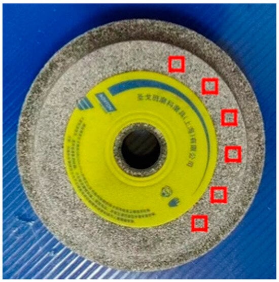
Figure 1.
Wheel photo.
The morphologies of abrasive particles were analyzed. It is concluded that the force state of the occluded part of the abrasive particle in the grinding process will be borne by the occluded abrasive particle. As shown in Figure 2, the red part represents the part of the occluded abrasive participating in grinding. In the process of modeling grinding force, it is important to determine the grinding contact angle between abrasive particle and workpiece for the accuracy of the model. Therefore, the adjacent wear particles forming the occlusion are recorded as double wear particles. Based on the spatial position relationship of the two abrasive sets in each grinding unit, four kinds of position relationships between abrasive particle a and abrasive particle b are summarized. The shape of the particle is assumed to be a regular cone shape. The spatial position relationship of the double abrasive sets is discussed, and the assumptions made are as follows:
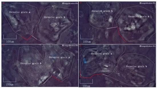
Figure 2.
Microscopic double wear particle distribution photograph.
- (1)
- The abrasive particles are distributed on the surface of the grinding wheel and do not fall off during grinding.
- (2)
- It is assumed that the abrasive particle is conical and its height is perpendicular to the direction of the involute.
- (3)
- In the process of grinding the gear, the contact arc length of the grinding surface is very short, so it is regarded as a straight line.
- (4)
- In the process of grinding force modeling, the influence of grinding temperature on the mechanical properties of tooth surface materials and abrasive crystals is not considered.
Based on the above research, the spatial position relationship diagram of the double abrasive sets is drawn and projected onto the mapping plane, as shown in Figure 3. On the grinding path, the spatial position relation of the double abrasive sets is represented by light cone and dark cone. The spatial position relation of the double abrasive sets is projected. The red area represents the degree of occlusion between the front and rear wear particles. The larger the red area is, the smaller the part of the occluded particle participating in grinding. At the same time, the blue shadow part becomes smaller, that is, the effective contact angle of the occluded particles in the grinding process gradually becomes smaller. The variation range of the effective contact angle of the occluded particle is represented by the polar coordinate system in the figure.
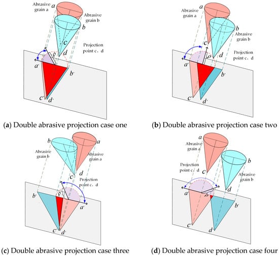
Figure 3.
Double abrasive group projection.
In the grinding process, the mechanism of action between the abrasive particle and the workpiece is transient and different from other abrasive particles. On the grinding path, as the grinding depth increases, the abrasive particles form mutual occlusion [18]. This directly affects the determination of effective cutting angle and effective cutting angle of abrasive particles. This results in substantial errors in the model. Therefore, the determination of the effective contact angle of abrasive particles in the grinding process is of great significance to the accuracy of the model. In order to further improve the accuracy of the grinding force model, the spatial dislocation occlusion relationship of double abrasive sets is discussed. Article group of double effective contact angle is divided into [, ], [, ], [, ], [, ] four interval periods.
3. Grinding Force Modeling
Grinding is a high-temperature, high-strain, high-strain rate material-removal process. Grinding force analysis and calculation are very important for understanding grinding mechanism. In the grinding process, scholars divided the grain–workpiece contact relationship into three states, namely, the slipping stage, the plowing stage and the cutting stage [38]. When the abrasive touches the surface of the workpiece in the friction stage, the workpiece material undergoes elastic deformation and produce scratches. The depth of abrasive grinding continues to increase, entering the plowing stage. The workpiece material has plastic deformation, and the chips accumulate and rise on the surface of the workpiece. In the cutting stage, the workpiece material is elastoplastic deformation, fracture and the formation of chips.
When the abrasive particles contact the workpiece material, the grain–workpiece force is distributed along the contact sphere between them. The grinding force is a physical phenomenon caused by the contact between the abrasive particle of the grinding wheel and the workpiece material when grinding the workpiece on the end face of the grinding wheel. It generally has three perpendicular components, which can be divided into normal force, tangential force and axial force along the grinding direction.
Because the force applied to the abrasive particle is symmetrical and the axial force is small and negligible, the grinding force can be expressed as follows:
3.1. Slipping Stage
In the abrasive friction stage, the material mainly deforms in elasticity. During the friction process, the abrasive particles do not remove the surface material of the workpiece, and the shape of the workpiece is be restored when the abrasive particles are cut out. The schematic diagram of abrasive particles in the slipping stage is shown in Figure 4.
Figure 4.
Schematic diagram of abrasive grain in slipping stage.
According to the Hertz contact theory, when the rigid cone contacts the elastic space, the strain in the deformation direction of the wear particle and the workpiece is as follows:
Therefore, the strain in the contact area can be expressed as follows:
represents the radius of the contact area at the grinding depth, is the penetration depth, is the workpiece’s Young’s modulus, and is Poisson’s ratio, where .
The formula is arranged to obtain the following formula:
is defined as the number of dynamic effective grains per unit area, so the total number of dynamic effective grains is expressed as follows:
where is the grinding contact width, is the grinding contact area, is the grinding contact arc length, and is the grinding wheel diameter.
Because of the randomness of the abrasive particles on the surface of the grinding wheel, the number of abrasive particles in the actual grinding process is less than that in the contact area of the workpiece of the grinding wheel. It is assumed that the proportion of dynamic effective abrasive number at the slip stage is , so the dynamic effective abrasive number participating in the grinding process at the slip stage can be expressed as follows:
In the shape grinding process of herringbone gear, because the tooth surface grinding contact width changes with the change in pressure angle , the grinding contact width can be expressed as follows:
where is the gear modulus, is the tip coefficient, is the tip clearance coefficient, and is the grinding depth.
Here, the average pressure P is equal to the strain σ in the contact area, so the normal force at the slip stage is as follows:
The formula is arranged to obtain the following formula:
During grinding, the dynamic mechanical properties of workpiece materials are very complicated. There is a size effect. Considering that the area of the wear plane increases during the sliding process, the workpiece may undergo elastoplastic deformation. Therefore, the friction coefficient is variable and can be expressed as follows [39]:
The wear plane can be expressed as follows:
Coefficients and can be queried by reference [39]. is the abrasive particle size. Thus, tangential force at the slipping stage can be expressed as follows:
The formula is arranged to obtain the following formula:
3.2. Plowing Stage
Unlike the slip stage, the workpiece material in this stage undergoes plastic deformation. When abrasive particles are grinding, there is a small amount of accumulation on the surface. The workpiece material flows along the grinding path to both sides, forming a plastic accumulation uplift. When grinding the workpiece with a single abrasive particle, the pressure along the surface is not constant, and the grinding force can be calculated by the integral equation.
The geometric relationship between the average grinding force per unit area and the force in any direction is shown in Figure 5. Thus, the force in any direction can be expressed as follows:
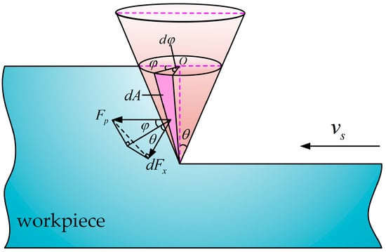
Figure 5.
Schematic diagram of grinding force in plowing stage.
It is considered that increases with the increase in cutting depth and feed speed and decreases with the increase in grinding wheel speed. Therefore, it is expressed by the following empirical formula:
The contact area between the abrasive particle and the workpiece can be expressed as follows:
Thus, in Equation (15) can be written as follows:
As shown in Figure 6, tangential plowing force and normal plowing force acting on a single abrasive particle can be expressed as follows:
where is the angle between any direction and the feed direction. Due to grinding grain, the effective contact angle can be divided into [, ], [, ], [, ], [, ] four contact situations. Therefore, the tangential plowing force and the normal plowing force are integrated separately under four grinding contact angles. The tangential grinding force of a single abrasive at the plowing stage is expressed as follows:
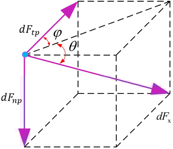
Figure 6.
Tangential plowing force and normal plowing force diagram.
The normal grinding force of a single abrasive at the plowing stage is expressed as follows:
In the above calculation, the upper and lower limits of the integral and are the effective cutting angle and effective cutting angle between the abrasive grain and the workpiece surface, respectively. Due to the different effective contact angles of abrasive grain, different grinding force formulas are obtained as shown above.
It is assumed that the ratio of dynamic effective abrasive number at plowing stage is . Therefore, the dynamic effective number of abrasive particles involved in the grinding process at the plowing stage can be expressed as follows:
Therefore, the tangential grinding force at the plowing stage is expressed as follows:
The normal grinding force at the plowing stage is expressed as follows:
The grinding contact angle is divided into four cases and discussed in detail; thus, tangential grinding force and normal grinding force correspond to four formulas.
3.3. Chipping Stage
With the feed movement of abrasive particles, the degree of plastic deformation of the workpiece increases. When the shear stress on the workpiece surface exceeds the shear limit, the material breaks and forms chips. The shape of the chip bulge on both sides of the chip-forming part is similar to that in the plowing stage. However, the material removal efficiency is higher in the chipping stage. The energy of the chipping process is composed of shear energy and friction energy.
Grinding specific energy is usually defined as the energy consumed per unit volume removal, which is expressed by the following formula:
where is the feed speed of the workpiece; is the grinding wheel speed; and is tangential grinding force. Figure 7 shows the schematic diagram of grinding force in chipping stage.
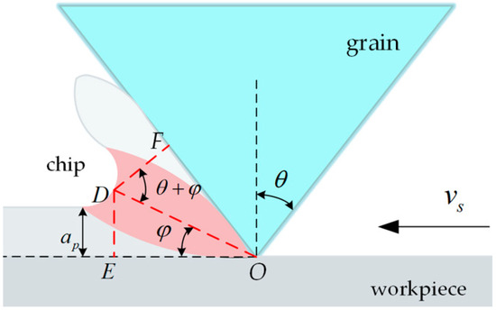
Figure 7.
Schematic diagram of grinding force in chipping stage.
According to the shear deformation theory, the formula of shear strain and shear strain rate is expressed as follows [7]:
According to reference [40], the shear energy is proportional to the logarithm of the shear strain rate:
Thus, the tangential grinding force of a single abrasive particle is as follows:
Assuming that the ratio of dynamic effective wear particle number at the plowing stage is , therefore, at the plowing stage can be expressed as follows:
Therefore, taking into account the dynamic effective number of abrasive grains, the tangential chip formation force is calculated as follows:
The friction coefficient of the chipping stage can be expressed as follows:
Therefore, the normal grinding force of the shear energy part is expressed as follows:
For the friction energy part, the average pressure in the contact area during the grinding of the workpiece can be seen as , that is, the hardness of the workpiece.
The tangential grinding force of the friction energy part can be solved by the friction coefficient, as follows:
According to the friction binomial theorem, the variable friction coefficient is given by the formula [39]:
where and are the coefficients, depending on the physical and mechanical properties of the contact interface.
Therefore, tangential grinding force and normal grinding force in chip-forming stage are expressed as follows:
4. Results and Discussion
The grinding force experiment of herringbone gear was carried out on Klingelnberg 1000 CNC grinding machine with chrome-corundum grinding wheel. The grinding wheel manufacturer is Saint-Gobain Abrasives Co., Ltd. (Shanghai, China). The manufacturer of this equipment is Harting Machine Tool Co., Ltd. (Shanghai, China). The diameter of the grinding wheel is 60 , the width is 20 and the aperture is 12 . Abrasive particle size of grinding wheel is 60#. The experimental photograph is shown in Figure 8. Experimental partial photographs are shown in Figure 9.
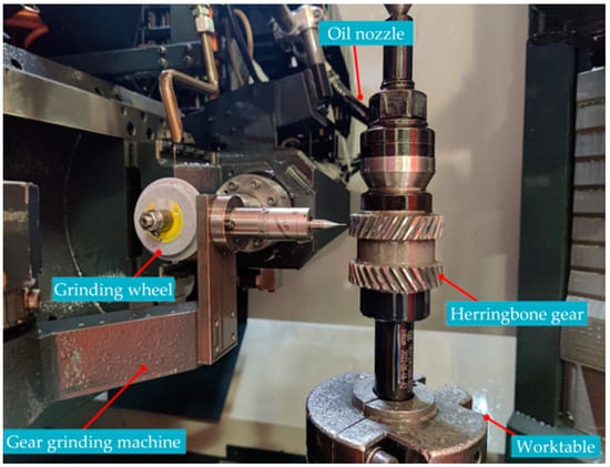
Figure 8.
Experimental photograph.
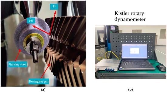
Figure 9.
Experimental partial photograph. (a) Grinding force direction. (b) Dynamometer photo.
Table 1 lists the structure parameters of the herringbone gear.

Table 1.
Herringbone gear structure parameters.
During grinding, the Kistler Rotary dynamometer is used to measure the grinding force. The dynamometer is connected to the charge amplifier Kistler. In this way, the grinding force of the tooth surface during grinding is transmitted to the dynamometer. Labview 2022 software is used to sample the grinding force signal at a sampling frequency of 25 . The measured grinding force signal is received and displayed in the computer. In gear-forming grinding without axial feed, the grinding force is composed of normal grinding force and tangential grinding force. Then, taking the and directions of the dynamometer, tangential and normal grinding forces are measured, respectively. The grinding force signals in the and directions are shown in Figure 10 and Figure 11. The grinding force data in the red box are selected for comparative analysis.
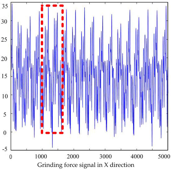
Figure 10.
Tangential force grinding force signal.
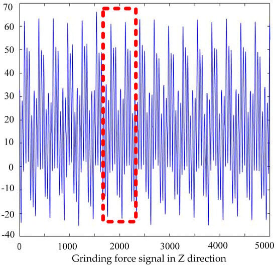
Figure 11.
Normal force grinding force signal.
Herringbone gears are heat-treated before grinding to obtain the desired surface. During the heat treatment process, the shape will change due to the release of residual stress, and the grinding depth will also change to an unknown value accordingly. Therefore, the herringbone gear needs to be pre-machined to achieve the required surface conditions before the experiment. During the grinding experiment, because the test period is short, the particle shedding phenomenon is not considered. The grinding wheel is trimmed before each grinding, and the grinding wheel is cleaned and restored to prevent grinding chips from clogging the surface pores of the grinding wheel and causing excessive heating. The phased modeling process is shown above, so the total tangential grinding force and total normal grinding force are superimposed on the forces in the sliding stage, plowing stage and chipping stage.
As shown in the following Equation (47),
Twenty groups of experimental data are randomly selected by a fractional factorial design. At the same time, the combination standard of process parameters is also referred to the actual production and processing site. The parameter of wheel circumferential speed, feed speed and grinding depth are shown in Table 2. The grinding oil content lasts 100% throughout.
Table 2.
Grinding parameters of herringbone gear.
Twenty groups of data were selected to carry out experimental verification analysis. The blue boxes represent predicted values, and the red circles represent experimental values. The statistical error diagrams of normal grinding force and tangential grinding force are shown in Figure 12 and Figure 13, respectively.
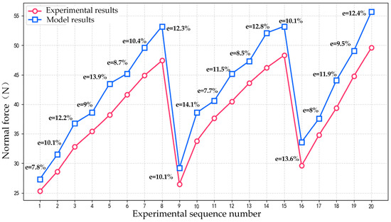
Figure 12.
Normal grinding force error line diagram.
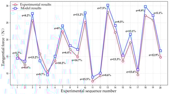
Figure 13.
Tangential grinding force error line diagram.
The statistical error diagrams of normal grinding force and tangential grinding force are shown in Figure 9 and Figure 10, respectively. The average error of tangential grinding force is 10.34%, and the average error of normal grinding force is 10.73%. The experimental results show that the error between the predicted value and the experimental value is within a reasonable range. The experimental results show that both normal and tangential grinding forces increase with the increase in cutting depth. The grinding force decreases with the increase in wheel speed, which is similar to the change trend of feed speed. In the range of parameters considered, the cutting depth has the greatest influence on the normal force and tangential force. The second is the feed speed. The influence of grinding wheel speed on normal force and tangential force is relatively small. The feasibility and effectiveness of the modeling process are proven, which lays a research foundation for high-precision machining of herringbone gear.
Figure 14 shows the tooth surface roughness measured after the experiment. Figure 15 shows the tooth surface roughness measured by other methods. Through the comparison of roughness, it is obvious that the tooth surface is smoother after machining by grinding force model. The surface quality of the tooth surface after machining is improved.
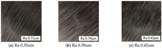
Figure 14.
The tooth surface roughness measured after the experiment.
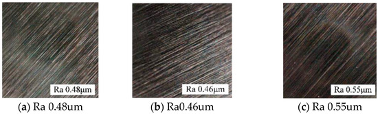
Figure 15.
The tooth surface roughness measured by other methods.
5. Conclusions
The modeling process of this paper starts from the grinding mechanism of a single abrasive particle. The removal mechanism of tooth surface material and the characteristics of disordered distribution of abrasive particles during grinding are considered. Based on the analysis of the displacement occlusion relationship between abrasive grains on the grinding wheel surface, the disordered arrangement of abrasive particles is simplified to the spatial position relation of any two sets of abrasive particles.
Based on the grinding state of the particle in different grinding stages, the friction coefficient and dynamic effective abrasive particle number of each grinding stage are determined. The microscopic mechanism of work–particle interaction is revealed.
At the same time, structural parameters, wear characteristics and workpiece attributes are integrated into the modeling process. The effective contact angle is also divided. The model of transient contact relationship between abrasive particles and workpiece is modified. The precision of grinding force model is further improved.
The error of grinding force model is caused by the simplified analysis of complex spatial position relationship of abrasive particles. At the same time, the accurate determination of the number of effective abrasive particles is also very important to improve the accuracy of the model. However, compared with other existing models, it still has advantages. The error range of other grinding force models is less than 13%, while the error range of the grinding force model in this paper is controlled within 11%. This research improves the precision of grinding force model and has good prediction performance. Repeated tests are also performed to assess the variability of the results. This model is suitable for the grinding of herringbone gear. The research foundation is laid for the development of herringbone gear grinding technology. Further in-depth scientific research will be carried out on the basis of this paper to continue to improve the accuracy of the model.
Author Contributions
Methodology, C.K.; Validation, Z.L.; Formal analysis, R.L.; Data curation, X.L. (Xianbin Li) and X.L. (Xianli Liu); Writing—original draft, C.K.; Writing—review & editing, R.L. and Z.Z.; Supervision, X.L. (Xianli Liu); Project administration, Z.Z. All authors have read and agreed to the published version of the manuscript.
Funding
This research was funded by Heilongjiang Natural Science Foundation Outstanding youth project grant number YQ2024E041 and by AECC Harbin Dongan Engine Co., Ltd. grant number DCGY230010.
Institutional Review Board Statement
Not applicable.
Informed Consent Statement
Not applicable.
Data Availability Statement
Data are contained within the article.
Conflicts of Interest
Author Zemin Zhao was employed by the company AECC Harbin Dongan Engine Co., Ltd. The remaining authors declare that the research was conducted in the absence of any commercial or financial relationships that could be construed as a potential conflict of interest.
References
- Park, H.W.; Liang, S.Y. Force modeling of micro-grinding incorporating crystallographic effects. Int. J. Mach. Tools Manuf. 2008, 48, 1658–1667. [Google Scholar] [CrossRef]
- Werner, G. Influence of work material on grinding forces. Ann. CIRP 1978, 27, 243–248. [Google Scholar]
- Malkin, S. Grinding mechanisms for metallic and nonmetallic materials. In Proceedings of the Ninth North American Manufacturing Research Conference, State College, PA, USA, 19–22 May 1981; SME: Southfield, MI, USA, 1981. [Google Scholar]
- Wang, D.; Ge, P.; Bi, W.; Jiang, J. Grain trajectory and grain workpiece contact analyses for modeling of grinding force and energy partition. Int. J. Adv. Manuf. Technol. 2014, 70, 2111–2123. [Google Scholar] [CrossRef]
- Ni, J.; Feng, K.; Al-Furjan, M.S.H.; Xu, X.; Xu, J. Establishment and verification of the cutting grinding force model for the disc wheel based on piezoelectric sensors. Sensors 2019, 19, 725. [Google Scholar] [CrossRef]
- Li, C.; Li, X.; Wu, Y.; Zhang, F.; Huang, H. Deformation mechanism and force modelling of the grinding of YAG single crystals. Int. J. Mach. Tools Manuf. 2019, 143, 23–37. [Google Scholar] [CrossRef]
- Li, B.; Dai, C.; Ding, W.; Yang, C.; Li, C.; Kulik, O.; Shumyacher, V. Prediction on grinding force during grinding powder metallurgy nickel-based superalloy FGH96 with electroplated CBN abrasive wheel. Chin. J. Aeronaut. 2021, 34, 65–74. [Google Scholar] [CrossRef]
- Dai, C.; Yin, Z.; Ding, W.; Zhu, Y. Grinding force and energy modeling of textured monolayer CBN wheels considering undeformed chip thickness nonuniformity. Int. J. Mech. Sci. 2019, 157, 221–230. [Google Scholar] [CrossRef]
- Zhang, Y.; Li, C.; Ji, H.; Yang, X.; Yang, M.; Jia, D.; Zhang, X.; Li, R.; Wang, J. Analysis of grinding mechanics and improved predictive force model based on material-removal and plastic-stacking mechanisms. Int. J. Mach. Tools Manuf. 2017, 122, 81–97. [Google Scholar] [CrossRef]
- Zheng, Z.; Huang, K.; Lin, C.; Zhang, J.; Wang, K.; Sun, P.; Xu, J. An analytical force and energy model for ductile-brittle transition in ultra-precision grinding of brittle materials. Int. J. Mech. Sci. 2022, 220, 107107. [Google Scholar] [CrossRef]
- Huang, X.; Guo, Y.; Guo, W.; Qi, B.; Ren, X.; Chai, Z.; Chen, X. Comprehensive investigations into the force and thermal characteristics of belt grinding Inconel 718 under constant normal forces. J. Manuf. Process. 2023, 99, 78–95. [Google Scholar] [CrossRef]
- Guo, G.; Gao, Q.; Wang, Q.; Pan, S. Study on grinding force of high volume fraction SiCp/Al2024 composites. Int. J. Adv. Manuf. Technol. 2023, 124, 3813–3822. [Google Scholar] [CrossRef]
- Meng, Q.; Guo, B.; Zhao, Q.; Li, H.N.; Jackson, M.J.; Linke, B.S.; Luo, X. Modelling of grinding mechanics: A review. Chin. J. Aeronaut. 2023, 36, 25–39. [Google Scholar] [CrossRef]
- Hecker, R.L.; Liang, S.Y.; Wu, X.J.; Xia, P.; Jin, D.G.W. Grinding force and power modeling based on chip thickness analysis. Int. J. Adv. Manuf. Technol. 2007, 33, 449–459. [Google Scholar] [CrossRef]
- Li, L.; Ren, X.; Feng, H.; Chen, H.; Chen, X. A novel material removal rate model based on single grain force for robotic belt grinding. J. Manuf. Process. 2021, 68, 1–12. [Google Scholar] [CrossRef]
- Jamshidi, H.; Budak, E. An analytical grinding force model based on individual grit interaction. J. Mater. Process. Technol. 2020, 283, 116700. [Google Scholar] [CrossRef]
- Rasim, M.; Mattfeld, P.; Klocke, F. Analysis of the grain shape influence on the chip formation in grinding. J. Mater. Process. Technol. 2015, 226, 60–68. [Google Scholar] [CrossRef]
- Wu, Z.; Zhang, L. Analytical grinding force prediction with random abrasive grains of grinding wheels. Int. J. Mech. Sci. 2023, 250, 108310. [Google Scholar] [CrossRef]
- Li, H.N.; Yu, T.B.; Wang, Z.X.; Da Zhu, L.; Wang, W.S. Detailed modeling of cutting forces in grinding process considering variable stages of grain-workpiece micro interactions. Int. J. Mech. Sci. 2017, 126, 319–339. [Google Scholar] [CrossRef]
- Chang, H.C.; Wang, J.J.J. A stochastic grinding force model considering random grit distribution. Int. J. Mach. Tools Manuf. 2008, 48, 1335–1344. [Google Scholar] [CrossRef]
- Guo, M.; Li, B.; Ding, Z.; Liang, S.Y. Empirical modeling of dynamic grinding force based on process analysis. Int. J. Adv. Manuf. Technol. 2016, 86, 3395–3405. [Google Scholar] [CrossRef]
- Meng, Q.; Guo, B.; Wu, G.; Xiang, Y.; Guo, Z.; Jia, J.; Zhao, Q.; Li, K.; Zeng, Z. Dynamic force modeling and mechanics analysis of precision grinding with microstructured wheels. J. Mater. Process. Technol. 2023, 314, 117900. [Google Scholar] [CrossRef]
- Fu, H.; Jiang, L.; Song, Q.; Liu, Z.; Tong, J.; Cao, C. Grinding surface roughness prediction for silicon nitride ceramics: A dynamic grinding force and frequency domain approach. Ceram. Int. 2023, 49, 35239–35253. [Google Scholar] [CrossRef]
- Yao, C.; Wang, T.; Xiao, W.; Huang, X.; Ren, J. Experimental study on grinding force and grinding temperature of Aermet 100 steel in surface grinding. J. Mater. Process. Technol. 2014, 214, 2191–2199. [Google Scholar] [CrossRef]
- Feng, W.; Zhang, K.; Cai, S.; Sun, C.; Sun, W.; Liu, B. A force model for face grinding using digital graphic scanning (DGS) method. Int. J. Adv. Manuf. Technol. 2021, 113, 3261–3270. [Google Scholar] [CrossRef]
- Wang, X.; Liu, Q.; Zheng, Y.; Xing, W.; Wang, M. A grinding force prediction model with random distribution of abrasive grains: Considering material removal and undeformed chips. Int. J. Adv. Manuf. Technol. 2022, 120, 7219–7233. [Google Scholar] [CrossRef]
- Mao, C.; Wang, J.; Zhang, M.; Wang, X.; Luo, Y.; Tang, W.; Tang, K.; Bi, Z.; Hu, Y.; Lin, Z. Prediction of grinding force by an electroplated grinding wheel with orderly-micro-grooves. Chin. J. Mech. Eng. 2023, 36, 116. [Google Scholar] [CrossRef]
- Li, X.; Zhang, X.; Shivpuri, R.; Yao, Z. A multi-scale model revealed in the grinding process and its influence on the grinding force and surface integrity. Int. J. Adv. Manuf. Technol. 2024, 130, 2811–2832. [Google Scholar] [CrossRef]
- Xia, C.; Wang, S.; Ma, C.; Wang, S.; Xiao, Y. Crucial geometric error compensation towards gear grinding accuracy enhancement based on simplified actual inverse kinematic model. Int. J. Mech. Sci. 2020, 169, 105319. [Google Scholar] [CrossRef]
- Zhou, W.; Tang, J.; Shao, W. Study on surface generation mechanism and roughness distribution in gear profile grinding. Int. J. Mech. Sci. 2020, 187, 105921. [Google Scholar] [CrossRef]
- Xiao, Y.; Wang, S.; Ma, C.; Wang, S.; Yang, W.; Xia, C.; Wang, J. Numerical modeling of material removal mechanism and surface topography for gear profile grinding. J. Manuf. Process. 2022, 76, 719–739. [Google Scholar] [CrossRef]
- Brecher, C.; Klocke, F.; Löpenhaus, C.; Hübner, F. Analysis of abrasive grit cutting for generating gear grinding. Procedia CIRP 2017, 62, 299–304. [Google Scholar] [CrossRef]
- Zhang, S.; Zhou, Y.; Zhang, H.; Xiong, Z.; To, S. Advances in ultra-precision machining of micro-structured functional surfaces and their typical applications. Int. J. Mach. Tools Manuf. 2019, 142, 16–41. [Google Scholar] [CrossRef]
- Zhang, X.; Kang, Z.; Li, S.; Shi, Z.; Wen, D.; Jiang, J.; Zhang, Z. Grinding force modelling for ductile-brittle transition in laser macro-micro-structured grinding of zirconia ceramics. Ceram. Int. 2019, 45, 18487–18500. [Google Scholar] [CrossRef]
- Yang, S.; Liang, R.; Chen, W.; Xu, P. Modelling and experiment for grinding forces of gear form grinding considering complete tooth depth engagement. Proc. Inst. Mech. Eng. Part B J. Eng. Manuf. 2022, 236, 1738–1750. [Google Scholar] [CrossRef]
- Ma, X.; Cai, Z.; Yao, B.; Chen, G.; Liu, W.; Qiu, K. Dynamic grinding force model for face gear based on the wheel-gear contact geometry. J. Mater. Process. Technol. 2022, 306, 117633. [Google Scholar] [CrossRef]
- Ardashev, D.V.; Dyakonov, A.A. Mathematical model of the grinding force with account for blunting of abrasive grains of the grinding wheel. J. Manuf. Sci. Eng. 2017, 139, 121005. [Google Scholar] [CrossRef]
- Huang, C.; Zhou, M.; Zhang, H. Investigations on the micro-interactions of grit-workpiece and forces prediction in ultrasonic vibration side grinding of optical glass. J. Mater. Process. Technol. 2022, 300, 117415. [Google Scholar] [CrossRef]
- Tang, J.; Du, J.; Chen, Y. Modeling and experimental study of grinding forces in surface grinding. J. Mater. Process. Technol. 2009, 209, 2847–2854. [Google Scholar] [CrossRef]
- Shumyacher, V.M.; Kryukov, S.G.; Kulik, O.G.; Kennedy, X. Materials grindability. MATEC Web Conf. 2019, 297, 09003. [Google Scholar] [CrossRef]
Disclaimer/Publisher’s Note: The statements, opinions and data contained in all publications are solely those of the individual author(s) and contributor(s) and not of MDPI and/or the editor(s). MDPI and/or the editor(s) disclaim responsibility for any injury to people or property resulting from any ideas, methods, instructions or products referred to in the content. |
© 2025 by the authors. Licensee MDPI, Basel, Switzerland. This article is an open access article distributed under the terms and conditions of the Creative Commons Attribution (CC BY) license (https://creativecommons.org/licenses/by/4.0/).