Article

Mechanical and Electrochemical Properties of Titanium Aluminum Nitride Coatings with Different Nitrogen Flow Rates on CrMnSi Steel by Filter Cathode Vacuum Arc Technology

by
Hongshuai Cao
1,
Xiao Ouyang
1,*,
Xianying Wu
1,
Lin Chen
2,
Jiakun Wu
2,*,
Jie Wu
2,
Junfeng Wang
3 and
Bin Liao
1
1
Key Laboratory of Beam Technology of the Ministry of Education, School of Physics and Astronomy, Beijing Normal University, Beijing 100875, China
2
College of Arts and Sciences, Beijing Normal University, Zhuhai 519087, China
3
Guangdong Dtech Technology Co., Ltd., Dongguan 523940, China
*
Authors to whom correspondence should be addressed.
Coatings 2025, 15(4), 379; https://doi.org/10.3390/coatings15040379
Submission received: 4 March 2025 / Revised: 20 March 2025 / Accepted: 21 March 2025 / Published: 24 March 2025

Abstract

:
In order to address the weaknesses of poor corrosion resistance of hydraulic cylinder piston rods, we have developed a surface protection strategy for titanium aluminum nitride coatings by filter cathode vacuum arc (FCVA) technology. The optimization and regulatory mechanism of N2 flow rate on the microstructure, mechanical, and electrochemical oxidation behaviors have been emphasized. The results indicated that all coatings revealed a nanocrystalline amorphous composite structure dominated by an fcc TiAlN phase. However, the solid solution content, growth orientation, and grain size could be controlled by the nitrogen flow rate, thereby achieving optimized hardness, adhesion strength, corrosion, and oxidation resistance. Specifically, with the increase in the N2 flow rate, the solid solution content continued to rise, while the crystal orientation transformed from the (111) to the (200) plane, and the grain size initially increased and then decreased. As a result, mechanical properties, including hardness, toughness, resistance to plastic deformation, and adhesion strength, displayed a trend of initially increasing and then decreasing. The corrosion failure of coatings was linked to surface defects controlled by the N2 flow rate, rather than the composition and phase structure. The coating displayed superior corrosion resistance at low N2 flow rates due to fewer macroscopic particles and pore defects. This study provides valuable insights into the corrosion behavior of an aluminum titanium nitrogen coating, providing crucial guidance for coating design in harsh environments.

1. Introduction

The stability of the hydraulic cylinder is crucial for the operational effectiveness of rocket launchers, as it directly impacts their performance. Typically, the primary causes of hydraulic cylinder oil leakage failures are frictional wear damage and fatigue resulting from the reciprocating motion of the piston rod. Low alloy ultra-high strength CrMnSi steel, known for its exceptional mechanical properties such as high toughness and superior fatigue strength, is considered an ideal material for hydraulic cylinder piston rods [1,2,3]. However, CrMnSi steel’s inadequate antioxidant properties present significant challenges under the high-temperature gas jet erosion generated during rocket launches, compromising the long-term durability of the piston rod [4]. In addition, the use of CrMnSi steel in piston rods poses additional challenges due to its poor corrosion and wear resistance [5,6]. Consequently, enhancing the mechanical properties, corrosion resistance, and oxidation resistance of piston rods is critical for maintaining the stability and reliability of rocket artillery operations.
Recently, researchers have developed various surface-strengthening treatment methods to address local corrosion and fatigue fractures in piston rods. These methods include electroplating, chemical plating, laser cladding, ion nitriding, and thermal spraying [7,8,9]. Among these techniques, electroplating is the most commonly used in the hydraulic industry to enhance the surface performance of components such as piston rods due to its simplicity and reliable product performance [10]. Electroplated chromium coatings are particularly favored for their high melting point, chemical stability, and corrosion resistance, making them the predominant choice for surface strengthening of hydraulic cylinder piston rods in rocket launcher systems. However, electroplated chromium coatings typically exhibit inherent porosity and microcracks [11]. These defects not only impair corrosion resistance but also facilitate crack propagation under high-temperature gas flow erosion, leading to coating delamination. Additionally, the limited antioxidant properties of metallic chromium do not ensure the long-term stable operation of the piston rod [12]. Therefore, it is imperative to investigate advanced coating materials with high hardness, corrosion resistance, and oxidation resistance, as well as their preparation techniques, to improve the surface protection of hydraulic cylinder piston rods in rocket launcher systems.
The titanium aluminum nitride (TiAlN) coatings, renowned for their high hardness, low friction coefficient, and superior resistance to corrosion and oxidation, demonstrate considerable potential for applications in high-temperature and high-wear conditions [13,14,15]. Additionally, TiAlN coatings exhibit strong adhesion properties, which ensure stability and durability, making them particularly suitable for surface modification of high-temperature alloy steels, stainless steels, and titanium alloys [16,17,18]. Filtered cathode vacuum arc (FCVA) technology, as a prominent physical vapor deposition method for hard coatings with good density and high adhesion, offers advantages such as high ionization rates, rapid deposition rates, and controllable ion energy [19,20,21]. The application of the FCVA technology for TiAlN coating on piston rods holds considerable promise for enhancing their surface properties [22]. However, the structural and performance characteristics of TiAlN coatings are highly dependent on the preparation process parameters. Ahlgren et al. [23] observed that Ti50Al50N coatings deposited via cathodic arc evaporation exhibited a transition in TiAlN orientation from the (200) to (111) plane with increasing bias voltage, accompanied by a gradual rise in compressive stress and hardness. Skordaris et al. [24] found that Ti60Al40N coatings prepared under high bias voltages showed improved mechanical properties and fatigue durability, although the adhesion strength was significantly reduced. Zhao et al. [25] further reported that an elevated bias voltage led to higher residual stresses in the coatings. Nonetheless, the coatings oriented to the TiAlN (200) plane demonstrated high toughness, with the increased residual stresses helping to inhibit the formation and propagation of thermal cracks. Moreover, adjusting the nitrogen content in TiAlN coatings has been shown to optimize their structure and performance. Typically, as nitrogen content increases, the TiAlN coating transitions from a columnar to a glassy structure, accompanied by variations in composition and an increase in defects. Li et al. [26] reported that decreasing the partial pressure of nitrogen initially led to an increase in aluminum content, which subsequently decreased, and resulted in a monotonic decrease in grain size. Higher aluminum content can cause lattice distortion, decrease the lattice constant, and affect the selective orientation of the coating, thus enhancing hardness. However, excessive aluminum content can lead to the formation of hexagonal AlN phases with lower hardness at the grain boundaries, reducing the overall hardness of the TiAlN coatings.
Recent studies have predominantly focused on optimizing the mechanical properties, wear behaviors, and adhesion strength of TiAlN coatings by adjusting parameters in cathodic arc and magnetron sputtering processes [26,27,28,29,30,31]. However, there is a notable lack of systematic research exploring the relationship between the process parameters of FCVA deposition and the microstructure, mechanical, electrochemical, and antioxidant properties of TiAlN coatings. Understanding this correlation is crucial for the design, preparation, and performance optimization of TiAlN protective coatings for hydraulic cylinder piston rods in rocket launcher systems using FCVA technology. Our previous work has preliminarily examined the effects of substrate bias and film structure on the properties of TiAlN coatings on aluminum alloy surfaces [32,33]. In this study, TiAlN coatings were prepared on 35CrMnSiA steel, a material used for rocket launcher hydraulic cylinder piston rods, with varying nitrogen flow rates using the FCVA method. The effect of nitrogen flow rate on composition, structure, mechanical, and electrochemical performance was studied. Furthermore, the correlation and regulatory mechanism between process parameters, structure, and properties of coatings had been constructed. The interface failure and corrosion failure mechanisms of titanium aluminum nitride coatings were also discussed. This research not only provides experimental insights for enhancing the surface performance of the hydraulic cylinder piston rod in rocket launcher systems but also offers guidance for the structural design and preparation of TiAlN coatings in various coupled environments.

2. Materials and Methods

In this work, 35CrMnSiA steel for the hydraulic cylinder piston rod of the rocket launcher device was used as the substrate. The substrate was processed to the size of 15 mm × 15 mm × 2 mm and manually ground to a mirror finish using SiC paper and woolen cloth. After that, the substrate was ultrasonically cleaned with alcohol for 15 min. Titanium aluminum nitride coatings were deposited by FCVA technology, with Ti67Al33 alloy as the cathode arc source and pure nitrogen as the reaction gas. The detailed details of the equipment have been mentioned in our previous reports [34,35]. Prior to the coating preparation experiment, the base pressure of the deposition chamber was evacuated to 4 × 10⁻³ Pa by a combination of mechanical pump and molecular pump. In order to remove the surface adsorbed impurities and passivation layer, the substrate was further cleaned by high-energy ion beam sputtering for 120 s under bias voltages of −800, −600, and −400 V before deposition. The deposition parameters for the single-layer titanium aluminum nitride coating were set to an arc current of 90 A, a filter duct current of 2.5 A, a negative bias of 75 V, and a deposition time of 60 min. The coatings with various nitrogen flow rates of 10, 20, 30, and 40 sccm were prepared to investigate their effects on microstructure, mechanical properties, and electrochemical behavior. The detailed coating deposition process parameters are summarized in Table 1.
The morphology and composition of the coating were investigated using a field emission scanning electron microscope (FESEM, FEI Nova Nano 230, USA) equipped with an energy dispersive spectrometer (EDS, Oxford X-Max20, UK). The 3D morphology and average roughness of the as-deposited coating were analyzed through an optical profilometer (SuperView W1, China). The phase structures of the coatings were characterized by X-ray diffraction (XRD, Rigaku UItimate IV, JEOL, Japan) with Cu Kα radiation (λ = 1.540598 nm). XRD measurements were performed with a scanning step of 0.167 °/s across a glancing angle range of 20° to 90°. The chemical bonding states of different elements in the coating were analyzed using X-ray photoelectron spectroscopy (XPS, Thermo k-Alpha, USA) with Al Kα irradiation (characteristic energy: 1.4867 keV), a pass energy of 30 eV, and an energy step of 0.05 eV. All XPS spectra were processed with Avantage software (version: Avantage 5.52) for data fitting. The microstructure of the coating was further observed through high-resolution transmission electron microscopy (HRTEM, Tecnai F20, USA). The hardness and elastic modulus of the coating were tested using a nanoindentation instrument (TI-900 Triboindenter, Hysitron, USA) at a maximum loading of 20 mN. The adhesion strength between the coating and the substrate was qualitatively analyzed by the morphology of the Rockwell indentation at a load of 60 Kgf. The corrosion resistance of the coating was evaluated in a 3.5 wt% NaCl solution for 24 h using an electrochemical workstation. Polarization tests were conducted over a potential range of −200 to +200 mV at a scanning rate of 1 mV/s. The polarization resistance (Rp) was determined via Tafel extrapolation using Origin software (version: origin 2022).

3. Results

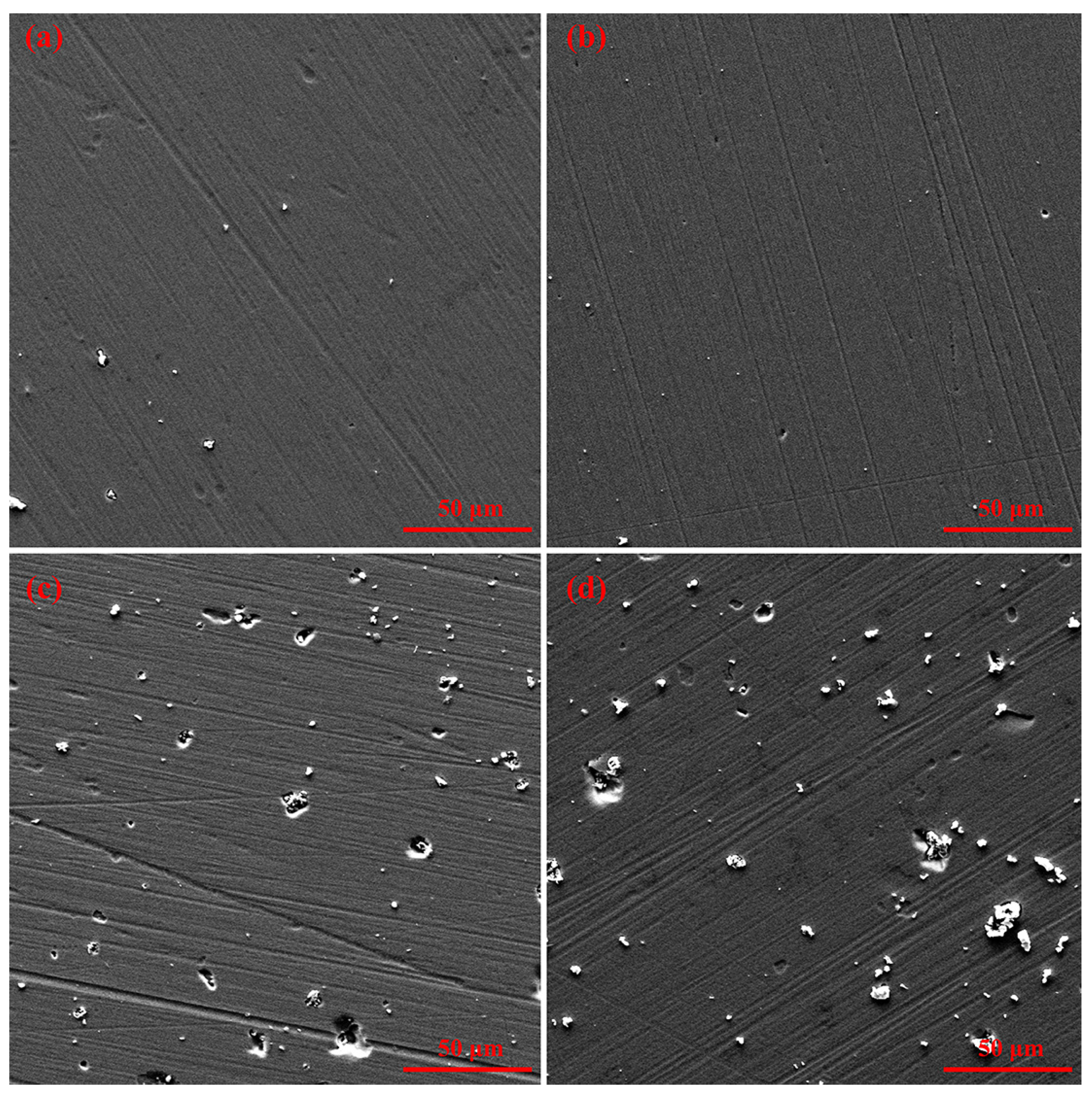
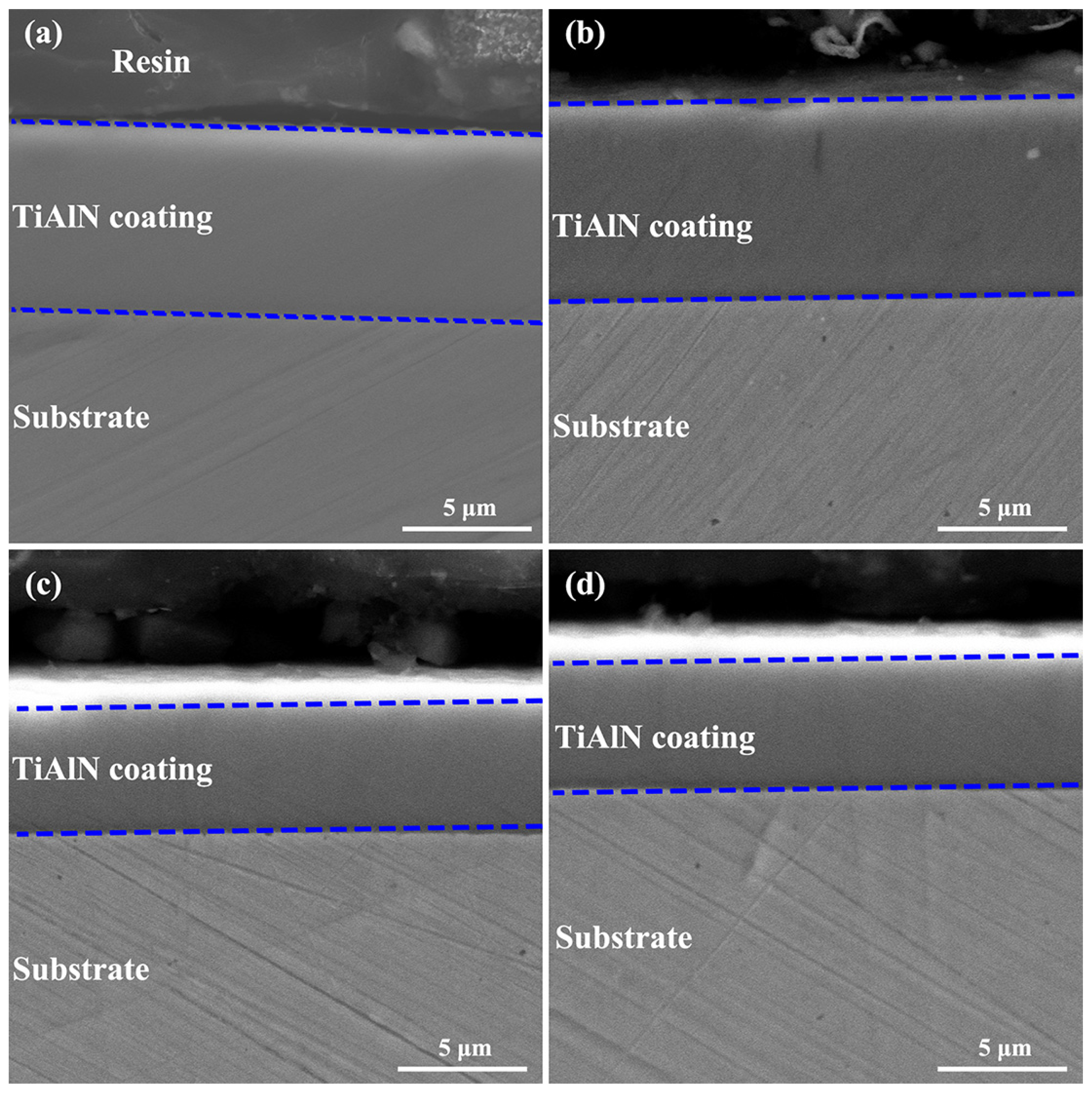
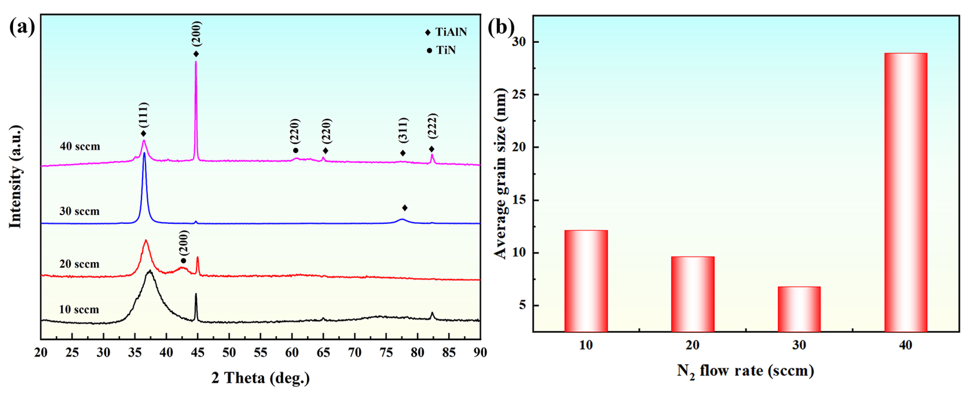
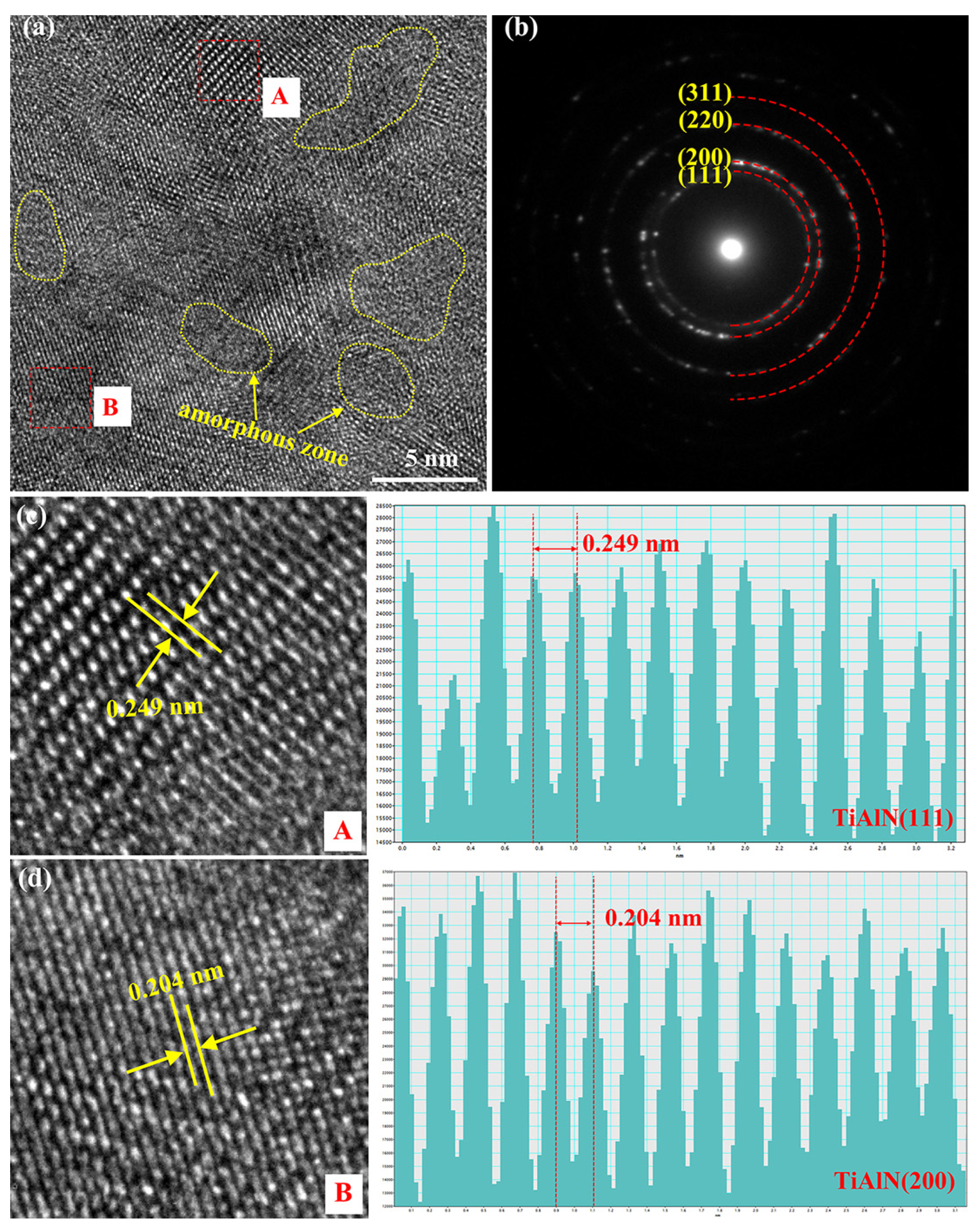
3.1. Structural Regulation of Coatings by Nitrogen Flow Rate

The surface morphology of the as-deposited coatings is shown in Figure 1. It can be seen that the titanium aluminum nitride coating exhibits a relatively uniform, flat, dense, and crack-free structure, with distinct “scratch” features. The surface characteristics are influenced by several factors, including the deposition method, the nature of the target material, and the surface properties of the substrate. The presence of scratches on the coating surface may be linked to the substrate’s surface characteristics. Additionally, some white macroscopic particles and pits are observed. In comparison with titanium aluminum nitride coatings reported in the literature [31,36,37], the number of macroscopic particles in this study is significantly reduced. This is attributed to the effective filtration of large droplets and uncharged particles generated from the target material, facilitated by the electromagnetic field. Macroscopic particles form due to the collision, aggregation, and growth of plasma containing Ti, Al, and N species on the substrate surface. During this process, weakly bonded macroscopic particles are dislodged by the incident particles, resulting in the formation of pits.
In addition, the number of macroscopic particle and pit defects depends on the nitrogen flow rate. As the N2 flow rate increases from 10 to 20 sccm, the number of defects decreases. However, by further increasing the N2 flow rate to 40 sccm, both the number and size of defects increase significantly. This phenomenon is due to the increase in the deposition pressure in the vacuum chamber due to the increased N2 flow rate, which in turn reduces the average free path of gas molecules. The relationship between the average free path of gas molecules (λ) and the deposition pressure (P) is given as follows:
λ = k T 2 π d 2 P
where k, T, d, and P are the Boltzmann constant, temperature, gas molecular diameter, and pressure, respectively. According to this equation, under identical deposition conditions, an increase in pressure results in a decrease in the average free path of gas molecules, thereby increasing the frequency of molecular and atomic collisions. This increased collision frequency enhances the degree of ionization, causing macroscopic particles to transition from an uncharged or negatively charged state to a positively charged state. These positively charged particles are attracted to the substrate surface by the applied negative bias, where they migrate and aggregate, forming macroscopic particles. Additionally, changes in the frequency of the molecule and atom can alter the energy dynamics of the plasma. Polakova et al. [38] reported that the energy delivered per unit volume (Epi) during the discharge collisions is related to the substrate bias (Us), substrate ion current density (is), and coating deposition rate (αD). Epi can be calculated using the following equation:
E p i = i s U s α D exp L λ i
The sheath thickness (L) and the average free range of the colliding molecules or atoms (λi), which are responsible for ion energy loss within the sheath, are key parameters influencing plasma dynamics. According to Equations (1) and (2), an increase in the N2 flow rate reduces the molecular mean free path, thereby diminishing the energy delivered to the coating. This energy loss leads to decreased plasma mobility, facilitating the aggregation and growth of macroscopic particles, which results in both a higher quantity and larger size of these particles. At higher N2 flow rates, the reduced energy also weakens the binding strength of macroscopic particles, making them more susceptible to being dislodged by the incident plasma, thus contributing to the formation of additional pit defects. Moreover, the lower incident energy promotes a higher plasma sub-doping rate, transferring excess energy to the coating’s surface [39]. This phenomenon is reflected in the observed increase in surface roughness, as shown in Figure 2.
Figure 3 displays the cross-sectional morphology of the as-deposited titanium aluminum nitride coatings. The coating exhibits a uniform and dense cross-sectional structure, with no obvious defects, such as cracks or large particles. In addition, there is no delamination at the interface between the coating and substrate. In general, the growth structure of the coating gradually transitions from a columnar crystal structure to a glassy structure with the increase in nitrogen [40]. According to Formulas (1) and (2), it can be inferred that higher energy plasma has a stronger surface diffusion ability at low N2 flow rates, which causes the coating to tend towards uniform columnar crystal growth. However, with the increase in the N2 flow rate, due to the decrease in plasma energy, the limited diffusion ability leads to an insufficient driving force for grain nucleation and growth. At this point, the coating exhibits a nanocrystalline amorphous composite structure. The growth mode of titanium aluminum nitride coating cannot be distinguished by the cross-sectional morphology due to the polishing sample preparation method. Based on our previous research [32,33], it can be inferred that the titanium aluminum nitride coating shows mainly a columnar crystal growth mode within the N2 flow rate range in this work. In addition, the thicknesses of titanium aluminum nitride coatings for N2 flow rates of 10, 20, 30, and 40 sccm are 7.39, 7.91, 5.78, and 5.26 μm, respectively.
The coating composition with various N2 flow rates, as tested by EDS, is summarized in Table 2. The results indicate that as the N2 flow rate increases, both the Al and N content gradually rise, while the Ti content decreases in the coating. Simultaneously, the Al/(Ti + Al) atomic ratio ranges from 0.090 to 0.224, all of which are smaller than that of the Ti67Al33 alloy target. Several factors may contribute to the lower Al content in the coating: (1) Dissociation degree difference: the vapor dissociation degrees of Ti and Al are approximately 80% and 50%, respectively [37]. During the coating preparation process, Ti, with a higher vapor dissociation degree, is preferentially ionized, leading to a higher Ti/Al atomic ratio in the coating than that of the alloy target. (2) Mass difference: because Al is lighter than Ti, it is more susceptible to secondary sputtering due to ion bombardment, resulting in a reduction in Al content in the coating [41]. (3) Difference in charge state distribution: the variation in Ti and Al content is related to the charge state distribution of the ions, with average charge states of +2.1 for Ti and +1.7 for Al, respectively [42]. During plasma transport, Al ions, with a lower average charge state, tend to diffuse more effectively outside the beam under the same electromagnetic field, leading to a higher deposition of Al on the filter tube surface. Furthermore, the Al/(Ti + Al) atomic ratio in the coating generally increases with the N2 flow rate, which may be due to the increasing content of the solid solution. However, the (Ti + Al)/N atomic ratio gradually decreases, likely due to the increased degree of target poisoning and the reduced average free range of the gas.
Figure 4 shows the XRD patterns and average grain size of coatings with various N2 flow rates. The results indicate that, except for a small amount of the TiN phase, all coatings display a typical fcc TiAlN phase structure, as exhibited in Figure 4a. The diffraction peaks at about 37.07°, 44.68°, 64.93°, 77.41°, and 82.29° represent the TiAlN (111), (200), (220), (311), and (222) planes, respectively. The diffraction peaks at 42.39° and 61.28° are attributed to the TiN (111) and (200) planes. Compared to the TiAlN, the TiN peaks have lower diffraction peak intensities, indicating that they are poorly crystalline and less abundant. Since the Al/(Ti + Al) ratio is lower than the maximum solid solubility limit of Al (approximately 0.7, as shown in Table 2), no hexagonal AlN phase is observed in the coating [43,44]. In addition, as the N2 flow rate increases, the preferred orientation transitions from TiAlN (111) to (200) planes. This behavior is similar to the results observed in arc-deposited titanium aluminum nitride coatings reported by Schramm and Zhao et al. [29,37] but differs significantly from the growth orientation transformation seen in titanium aluminum nitride coatings deposited by reactive magnetron sputtering, as reported by Niu and Charkrabarti et al. [45,46]. This suggests that titanium aluminum nitride coatings’ growth orientation is strongly dependent on the deposition technology.
According to the literature reports [26], the preferred orientation is regulated by thermodynamic mechanisms, that is, for face-centered cubic structures, coatings tend to grow preferentially along the (111) crystal plane with the lowest free energy, followed by the (220) crystal plane. Thus, it is understandable that the coating grows preferentially along the (111) plane under low N2 flow rates. The solid solution content increases with higher N2 flow rates, and the degree of lattice distortion also rises due to the higher Al content, bringing about an adjustment of the preferred orientation to the (200) plane. However, this cannot explain the phenomenon where the texture coefficient of TiAlN (111) orientation gradually increases from 0.651 to 0.969 as the N2 flow rate increases from 10 to 30 sccm. In addition to thermodynamic mechanisms, kinetic mechanisms also play a role in determining the growth orientation. The growth orientation of the deposited coating is influenced by the diffusion ability of the plasma, which is determined by the diffusion energy and diffusion time [47]. For face-centered cubic structures, the (111) orientation has a lower atomic diffusion rate compared to the (200) orientation, which explains why the coating with a N2 flow rate of 10 sccm prefers the (111) orientation. As the N2 flow rate increases from 10 to 30 sccm, the diffusion ability of the plasma decreases due to the incremental loss associated with a reduced average free path. This results in a gradual increase in the texture coefficient of the TiAlN (111) orientation, while the texture coefficient for the (200) orientation decreases. However, by further increasing the N2 flow rate to 40 sccm, the diffusion ability of the plasma is enhanced due to a decrease in the deposition rate, which extends the atomic diffusion time despite energy losses in the plasma. This leads to the transition of the preferred orientation from the (111) to (200) planes. Thus, it can be concluded that the TiAlN growth orientation is jointly regulated by both thermodynamic and kinetic mechanisms.
In order to further illustrate the change in the grain size of titanium aluminum nitride coating with the increase in N2, the average grain size is calculated by the Scherrer equation based on the (111) and (200) orientations. As shown in Figure 4b, when N2 is increased from 10 to 30 sccm, the average grain size decreases from 12.12 to 6.77 nm. Due to the energy loss caused by the increase in the average free path, the weakening of the kinetic energy and atomic diffusion rate of the plasma on the substrate surface reduces the activity of grain boundaries, which is not conducive to grain growth. In addition, the increase in the amorphous phase and internal stress caused by lattice distortions are also responsible for the grain refinement. However, by further increasing the N2 to 40 sccm, the average grain size suddenly increases to 28.95 nm. This may be related to the increase in the degree of target poisoning and the transformation of growth orientation. It can be suggested that grain refinement can be achieved by appropriately increasing nitrogen.
Figure 5 reveals the XPS spectra and corresponding fitting results for the coatings. In addition to Al, Ti, and N, oxygen is also detected, likely originating from adsorbed contaminants. In addition, the coatings with various nitrogen flow rates have similar high-resolution XPS spectra. In Figure 5a, the typical bimodal characteristics of the Ti2p3/2 and Ti2p1/2 states can be seen in Ti2p spectra, which are further fitted as three sets of doublet peaks using a Gauss–Lorentz function. The doublet states are demonstrated in the same color and the corresponding binding energy (BE) of the Ti2p2/3 state at the low energy side is between 452 and 460 eV, as revealed in Figure 5b. The BE values at 454.4 ± 0.2, 456.3 ± 0.4, and 458.3 ± 0.2 eV are identified as Ti-Al-N bonds (TiAlN compound) [31,48], Ti-N-O bonds (TiNxOy compound) [49], and Ti-O bonds (TiO2) [22], respectively. The intensity of the Ti-Al-N bonds gradually increases with increasing N2 flow rate, indicating a higher content of the TiAlN solid solution. Moreover, the peak intensities for the oxide TiNxOy and TiO2 are significantly higher than those of TiAlN, which is attributable to the high partiality of the interstitial place of Ti for oxygen atoms [50]. In the Al2p spectra, a single characteristic peak is observed at a BE value of about 73.5 ± 0.2 eV, corresponding to the non-chemiscale AlNx compound or the TiAlN ternary compound. Based on the fitting analysis of the Ti2p spectra, this characteristic peak is determined as Al-Ti-N bonds in the TiAlN compound, consistent with the results reported by Rizzo et al. [51]. In addition, the N1s spectra in Figure 5f can be fitted as four peaks located at 395.7 ± 0.2 eV, 396.4 ± 0.3 eV, 398.0 ± 0.3 eV, and 399.7 ± 0.2 eV, corresponding to N-Al-Ti bonds (TiAlN), N-Ti bonds (TiN), N-Ti-O bonds (TiNxOy), and adsorbed impurities [49,51], respectively. Among them, the intensity of the N-Al-Ti bond peak shows a noticeable increase trend with higher N2 flow rates (Figure 5e), further providing evidence for the increase in TiAlN solid solution. Furthermore, the O1s spectra exhibit two characteristic peaks related to the formation of TiO2 and Al2O3 oxides, with BE values around 530.2 ± 0.3 and 532.1 ± 0.2 eV [51]. The atomic chemical bonding states are based on TiAlN, TiN, TiO2, TiNxOy, Al2O3, and a small amount of adsorbed organic contaminants. Similar to XRD, XPS results further confirm that Al atoms are dissolved into the TiN lattice to form TiAlN solid solutions, with only a small amount of TiN remaining in the coating. The increase in TiAlN solid solution content with higher N2 flow rates, as shown in Table 2, also helps explain the gradual rise in Al content in the coating.
The microstructure of the coating with a N2 flow rate of 30 sccm is further investigated by TEM. As shown in Figure 6a, regular lattice stripes can be clearly observed in the HRTEM image, indicating good crystallization characteristics. In addition, distinct amorphous regions are observed surrounding the lattice stripes. In Figure 6b, the wide and diffusely distributed diffraction rings indicate that the titanium aluminum nitride coating has typical polycrystalline features. By calibrating the diffraction rings from the transmission point to the outer part, the diffraction rings are identified as corresponding to rgw TiAlN (111), (200), (220), and (311) planes. Figure 6c,d is obtained via Inverse Fast Fourier Transform (IFFT) from selected regions A and B in Figure 6a. The crystal plane spacings of 0.249 and 0.204 nm, corresponding to the (111) and (200) planes of the TiAlN phase, are clearly visible in the selected regions. These TEM results provide direct evidence that the coating possesses a typical fcc TiAlN solid solution structure, which is in agreement with the XRD and XPS analyses.

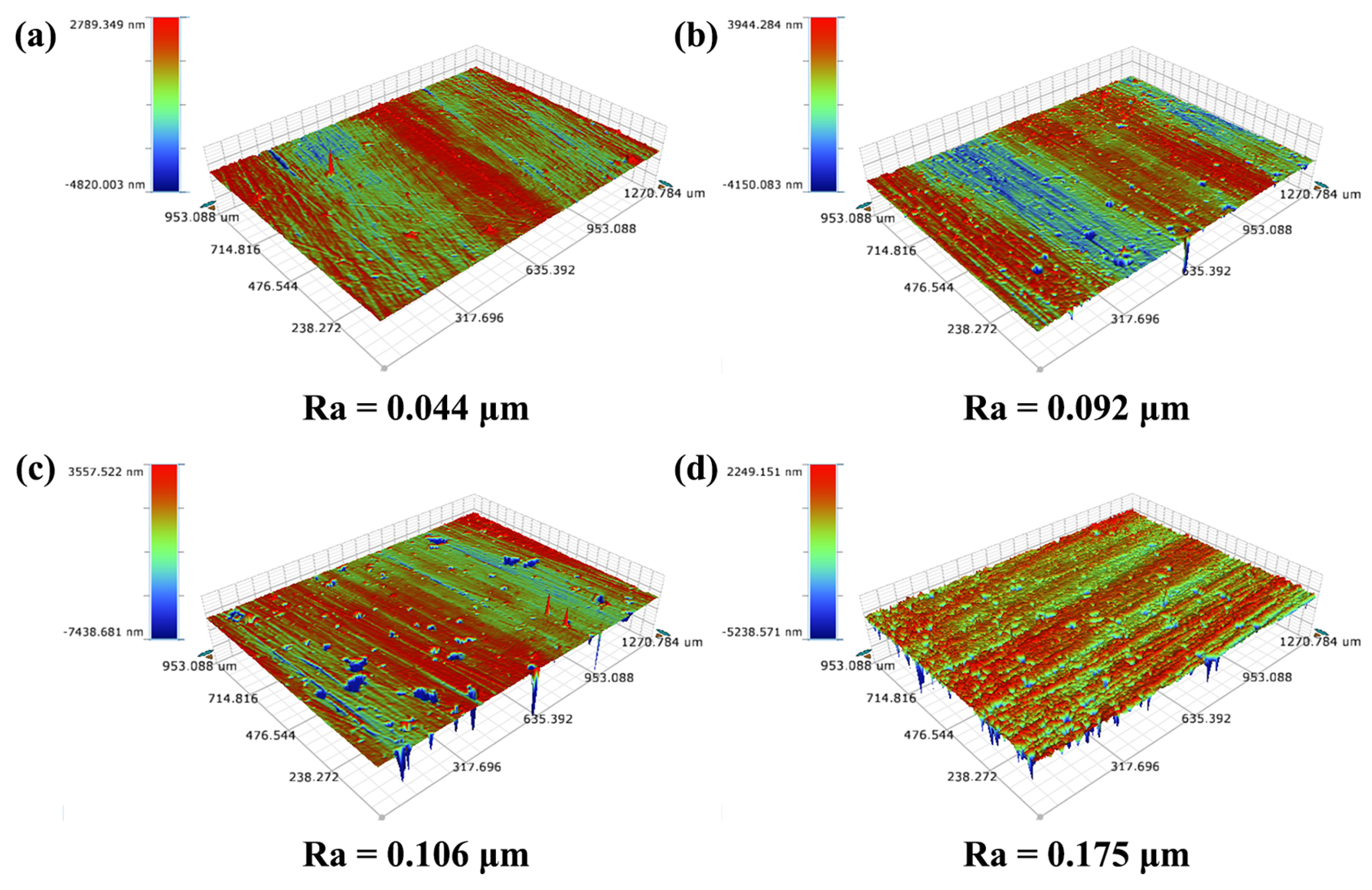
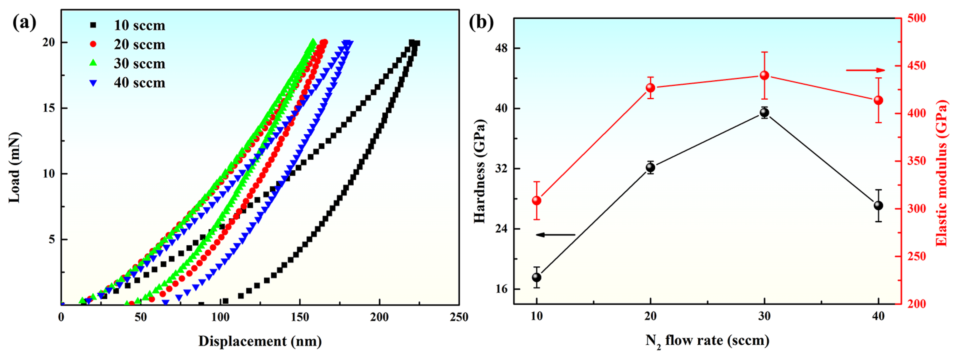
3.2. Mechanical Behaviors Regulation of Coatings by Nitrogen Flow Rate

Figure 7 displays the typical load–displacement curves, hardness, and elastic modulus values for titanium aluminum nitride coatings with various nitrogen flow rates. The indentation depth increases with the increase in loading load revealed in Figure 7a. At the early stage of loading, the load and displacement are basically linear, that is, the coating surface undergoes elastic deformation. As the loading load increases, the load and displacement exhibit a nonlinear relationship, at which time the coating surface undergoes plastic deformation. Subsequently, the elastic deformation recovers while the plastic deformation retains a residual indentation depth in the coating during the unloading process. The hardness and elastic modulus are obtained from the load–displacement curves by Oliver and Pharr method as demonstrated in Figure 7b. The hardness and elastic modulus of titanium aluminum nitride coating range from 17.5 to 39.5 GPa and 308.5 to 439.8 GPa, respectively. With the increase in N2 flow rate, the hardness and elastic modulus have the same trend, that is, increase first and then decrease. The mechanical properties are related to the composition, structure, and stress state of the coatings.
As the N2 flow rate increases from 10 to 30 sccm, the hardness of the coating increases due to several factors: (1) the decrease in (Ti + Al)/N atomic ratio, as shown in Table 2, which indicates an increase in covalent bonding, thereby enhancing hardness; (2) according to the Hall Patch relationship [25], grain refinement impedes dislocation movement, contributing to higher hardness; and (3) an increase in the N2 flow rate leads to more Al atoms replacing Ti atoms in TiN, forming the TiAlN phase, which induces internal stress due to lattice distortion. Meanwhile, the substituted Ti atoms can produce a pinning effect that hinders the dislocation slip, further enhancing hardness. However, as the N2 flow rate increases from 30 to 40 sccm, the coating’s hardness gradually decreases, likely due to two factors: (1) an increase in average grain size reduces the number of grain boundaries, weakening the hindrance to dislocations; and (2) The preferred orientation shifts to the (200) crystal plane, which exhibits lower hardness than the TiAlN (111) plane [22].
Furthermore, as listed in Table 3, the values of H/E, H3/E2, and We follow a similar trend, initially increasing and afterward diminishing with the increment of N2 flow rate. When the N2 flow rate is 30 sccm, the titanium aluminum nitride coating has the highest hardness and the best resistance to cracking and plastic deformation. In comparison, the hardness, elastic modulus, H/E, H3/E2, and We values for the 35CrMnSiA steel substrate are approximately 4.5 GPa, 335.2 GPa, 0.013, 0.0008 GPa, and 6.5%, respectively. Compared to the uncoated substrate, the mechanical properties of the titanium aluminum nitride coated substrate have been obviously improved, which is beneficial for developing the wear resistance applied in piston rods.
Figure 8 presents the SEM backscattering morphology of Rockwell indentations of titanium aluminum nitride coatings deposited by varying the N2 flow rates. At a N2 flow rate of 10 sccm, numerous radial cracks extend from the indentation center towards the periphery, resulting in minor coating delamination. According to the standard Rockwell rating index for hard coatings [52], the adhesion strength is classified as HF 3. With an increase in the N2 flow rate to 30 sccm, the occurrence of radial cracks is significantly reduced, and no noticeable coating delamination is observed. This enhancement in toughness and resistance to cracking improves adhesion from HF 3 to HF 1. However, when the N2 flow rate is increased to 40 sccm, a distinct circumferential ring crack appears at the edge of the Rockwell indentation, accompanied by a large number of tiny spalling along its perimeter. This indicates a notable reduction in adhesion strength to HF 3 due to diminished crack resistance and toughness. Overall, the Rockwell indentation test results reveal a trend where adhesion strength between the coating and the substrate uncovers a pattern of first increasing and afterward diminishing with the increment of N2 flow rate. The titanium aluminum nitride coating at 30 sccm exhibits the highest adhesion strength.

3.3. Electrochemical Performance Regulation of Coatings by Nitrogen Flow Rate

Figure 9 shows the potentiodynamic polarization curves of titanium aluminum nitride coatings after 24 h of corrosion in 3.5 wt% NaCl solution. In general, corrosion potential (Ecorr) and corrosion current density (icorr) are used as kinetic indicators to evaluate the corrosion resistance of coatings. A more positive Ecorr indicates better corrosion resistance, while a lower icorr suggests fewer electrons are transferred, indicating stronger c [36]. As the N2 flow rate increases from 10 to 30 sccm, Ecorr shifts negatively from −0.297 to −0.682 V, indicating reduced corrosion resistance. By further increasing the N2 flow rate to 40 sccm, the Ecorr slightly improves to −0.605 V, similar to the coating with a N2 flow rate of 30 sccm. The icorr, obtained by fitting the kinetic potential polarization curve using the Tafel extrapolation, is listed in Table 4. The coating with a N2 flow rate of 10 sccm shows the best corrosion resistance with the lowest icorr value of 0.671 μA∙cm−2. However, as the N2 flow rate increases, icorr rises slowly, indicating diminished resistance to corrosive ion attack. This trend is further confirmed by the polarization resistance (Rp), calculated using the Stern–Geary Equation (3):
R p = β c × β a 2.3 × i corr × β c + β a
where βc and βa represent the slopes of the cathodic and anodic curves, respectively, and icorr is the corrosion current density. As shown in Table 4, the coating with a N2 flow rate of 10 sccm exhibits the highest Rp value of approximately 56.83 kΩ∙cm2, indicating the lowest corrosion rate and the strongest resistance to corrosion ions. Increasing the N2 flow rate to 40 sccm leads to a rapid decrease in Rp value to about 13 kΩ∙cm2, reflecting reduced corrosion resistance. In brief, the corrosion resistance of the coating gradually decreases with the increase in N2 flow rate, consistent with the trends in corrosion potential and corrosion current density.
To further characterize the coating’s ability to protect the substrate, the protection efficiency (E) of the coating is calculated based on the polarization test results using Formula (4) [53]:
E % = 1 I corr / I corr 0 × 100 %
where Icorr and I corr 0 are the corrosion current densities of the coating and substrate (4.474 μA∙cm−2), respectively. The E values of coatings with the N2 flow rates of 10, 20, 30, and 40 sccm are about 85.00%, 81.67%, 73.85%, and 59.88%, respectively, indicating a decrease in protection efficiency with the increase in the N2 flow rate. The corrosion resistance is also linked to the coating’s porosity (P), calculated using the following Equation (5) [53]:
P ( % ) = R ps / R pc × 10 E corr β a × 100
where Rps and Rpc are the polarization resistances of the substrate and coating, respectively, ∆Ecorr is the corrosion potentials difference between the substrate and coating, and βa is the anodic slope of the Tafel curve of the coating. The p values of coatings with the N2 flow rates of 10, 20, 30, and 40 sccm are 7.93%, 13.77%, 37.20%, and 37.16%, respectively, with lower P indicating better corrosion resistance. In summary, the titanium aluminum nitride coating with a N2 flow rate of 10 sccm exhibits the best corrosion resistance, characterized by the most positive corrosion potential, smallest corrosion current, largest polarization resistance, and highest protection efficiency, attributed to its higher densification and the lower porosity.
Figure 10 presents the corrosion morphology of the coatings with varying N2 flow rates. At 10 sccm, the corroded coating remains uniform and flat structured, without cracks or corrosion pits, representing outstanding corrosion resistance. The formation of inert oxides leads to a dense particle structure (Figure 10e). However, as the N2 flow rate increases to 20 sccm, a small number of white corrosion pits and black areas appear, acting as pathways for the corrosion medium to accelerate coating degradation. Simultaneously, the coating becomes loose and non-uniform with a slight layering phenomenon (Figure 10f), reflecting an increase in the degree of corrosion. Further increasing the N2 flow rate to 30 sccm, corrosion resistance significantly declines, as evidenced by the formation of large corrosion pits and cracks accompanied by the agglomeration of loose corrosion products. At 40 sccm, although no large corrosion pits or cracks are observed, a widespread non-uniform distribution of corrosion defects is evident in Figure 10h, suggesting a non-uniform corrosion mode. Furthermore, compared to before corrosion, macroscopic particles disappear, indicating that these defects contribute to reduced corrosion resistance by forming open defects that accelerate corrosion.
Figure 11 displays the morphology and corresponding EDS images of the post-corrosion coating with a N2 flow rate of 30 sccm. Compared to before corrosion, Ti, Al, and N contents sharply decrease, while O content increases significantly, as shown in Figure 11b. This indicates that, under the erosion of NaCl corrosive medium, the nitride phase decomposes, resulting in the formation of oxide products. The presence of C is due to surface impurities, and Fe and Ni arise from substrate diffusion along corrosion pits or voids to the coating surface. In the corrosion pit (Figure 11c), the composition is dominated by Fe and O, confirming the formation of open defects that penetrate the substrate. Element mapping (Figure 11d–i) shows Fe and O concentrated in the corrosion pits, which further proves that the coating has been removed from the substrate surface. The corrosion products likely include iron oxides, such as Fe3O2 and FeO, which detach easily due to their loose structure, form large corrosion pits and cracks. In the non-corrosive pit area, Ti, Al, N, and O elements dominate, with lower O content where N content is relatively high, indicating partial nitride phase decomposition and oxidation to form a dense passivation film, such as Al2O3 and TiO2. The above results suggest that titanium aluminum nitride coatings undergo non-uniform corrosion, with areas of severe corrosion, passivation, and intact coating, primarily due to the uneven distribution of macroscopic particle and pore defects.
The corrosion failure mechanism of titanium aluminum nitride coatings is mainly influenced by surface defects, such as macroparticles and pores. These defects and corrosive media are necessary for the formation of galvanic cells between the coating and the substrate, accelerating localized corrosion and delamination [54]. Wang et al. [55] proposed that the local corrosion process initiates with the galvanic corrosion of the N-contaminated droplet edges, which acts as the anode relative to the adjacent coating nitride. This galvanic interaction generates solution pathways that eventually expose the substrate. Similarly, Sugumaran et al. [56] also found that embedded droplets (either fully or partially covered) play a significant role in the localized corrosion mechanisms of the coating. Due to the heterogeneous local composition, the metal core of the droplets forms multiple galvanic couples and acts anodically, leading to the partial or complete dissolution of the droplets. As illustrated in Figure 10, the absence of macroscopic particles after corrosion indicates that these defects initiate pitting corrosion. Macroparticles dissolve during the corrosion process, forming black corrosion products at the interface, leading to delamination, detachment, and eventually the arrangement of white pores. The open pores generated by the removal of weakly bound macroscopic particles, as well as the pores and pinholes generated by mask effects on the coating surface, can serve as effective pathways for the corrosion medium to diffuse into the substrate. Over time, the corrosion intensifies in these pitting areas and expands towards the surrounding areas, ultimately leading to complete detachment of the coating in the pitting center area and exposure of the substrate. Macroparticles not only increase surface roughness and porosity but also reduce the local adhesion strength, which is not conducive to corrosion resistance. Chen et al. [57] found that pitting corrosion originates at surface defect sites, such as large particles, where the dissolution of these particles at the coating/particle interface generates corrosion products and forms open pits on the film. Therefore, defects act as pathways for localized corrosion and damage propagation. This can explain well the variation law of the corrosion resistance of the titanium aluminum nitride coating with the N2 flow rate: at low N2 flow rates (≤20 sccm), the coating manifests excellent corrosion resistance due to fewer defects, while at higher N2 flow rates (≥30 sccm), increased macroparticle defects lead to a significant decrease in corrosion resistance. Additionally, the corrosion of titanium aluminum nitride coating in NaCl solution involves several reactions:
TiAlN + 7 H 2 O = 2 TiO 2 + Al 2 O 3 + 2 NH 3 + 4 H 2
2 TiN + 4 H 2 O = 2 TiO 2 + 2 NH 3 + H 2
2 TiN + 3 H 2 O = Ti 2 O 3 + 2 NH 3
Al 2 O 3 + 2 NaCl + H 2 O = 2 HCl + 2 NaAlO 2
TiO 2 + 2 NaCl + H 2 O = Na 2 TiO 3 + 2 HCl
Ti 2 O 3 + 2 NaCl + H 2 O = 2 NaTiO 2 + 2 HCl
The Gibbs free energies of the hydration reactions (6)–(8) at room temperature are −1370.58, −233.33, and −268.0 kJ/mol, respectively. During corrosion in NaCl solution, TiAlN is more likely to undergo hydration reactions due to lower Gibbs free energy, forming inert oxides like TiO2 and Al2O3. Compared to titanium oxides, Al2O3 benefits from higher density and chemical stability, which can more effectively slow down further corrosion of the coating by corrosive media and improve corrosion resistance [58]. As corrosion progresses, the passivation film can degrade, generating salt products, such as NaAlO2, NaTiO2, or Na2AlO3, that are accompanied by surface structure loosening (as shown in Figure 10). In addition to the influence of defects, a high Al content in the coating is conducive to the formation of a dense inert Al2O3 film during the corrosion process, resulting in better corrosion resistance. However, in this article, although the Al content in the coating increases with the increase in N2 flow rate, the corrosion resistance actually shows a decreasing trend. This further confirms that the corrosion failure of titanium aluminum nitride coating is primarily driven by macroparticle and pore defects.

4. Conclusions

In this study, ternary titanium aluminum nitride ceramic coatings with various N2 flow rates were deposited on a 35CrMnSiA steel substrate for the piston rod of a rocket launcher hydraulic cylinder by the FCVA method. The effects of N2 flow rate on the microstructure, mechanical properties, and corrosion resistance of the coating were investigated, with a detailed exploration of the underlying mechanisms regulating the structure and performance. The main conclusions are as follows:
(1) The coatings with various N2 flow rates have a face-centered cubic TiAlN solid solution-dominated structure. As the N2 flow rate increases from 10 to 30 sccm, the N content gradually increases, in the meantime the texture coefficient of the TiAlN (111) plane increases and the grain size decreases. By further increasing the N2 flow rate to 40 sccm, the N content continues to increase, but the growth orientation changes to the TiAlN (200) plane controlled by dynamic and thermodynamic mechanisms. Additionally, the grain size increases sharply, and the coating undergoes a transition from a smooth and flat structure to a rough structure with macroscopic particle and pore defects.
(2) The hardness of the coatings increases from 17.5 to 39.5 GPa as the N2 flow rate increases from 10 to 30 sccm, primarily due to solid solution strengthening and grain refinement. Concurrently, the H/E, H3/E2, and We values show a gradual increase, indicating improved toughness and resistance to plastic deformation. This leads to enhanced crack propagation resistance and an increase in adhesion strength. However, when the N2 flow rate is increased to 40 sccm, the transformation in TiAlN growth orientation and the significant increase in grain size result in a deterioration of mechanical properties.
(3) The electrochemical performance of coatings is affected by surface defects controlled by the N2 flow rate. The corrosion current density rises from 0.671 to 1.795 μA∙cm−2, and protection efficiency reduces from 85.00% to 59.88% with the increase in N2. The increase in porosity caused by microstructure with macroscopic particle and pore defects is a key factor in the decrease in corrosion resistance. The proliferation of damage propagation pathways is primarily to blame for titanium aluminum nitride coatings’ failure to resist corrosion.

Author Contributions

Conceptualization, H.C. and X.O.; methodology, X.W.; software, H.C. and X.O.; validation, L.C., J.W. (Jiakun Wu) and J.W. (Jie Wu); formal analysis, H.C. and J.W. (Jiakun Wu); investigation, H.C. and X.O.; resources, L.C. and B.L.; data curation, H.C., X.O. and J.W. (Jiakun Wu); writing—original draft preparation, H.C. and X.O.; writing—review and editing, H.C., X.O. and J.W. (Jiakun Wu); visualization, J.W. (Jie Wu); supervision, J.W. (Junfeng Wang) and B.L.; project administration, B.L. All authors have read and agreed to the published version of the manuscript.

Funding

This research was funded by the Postdoctoral Fellowship Program of CPSF, grant number GZC20230259; the Fundamental Research Funds for the Central Universities, grant number 2021NTST14; the National Natural Science Foundation of China, grant number 12205016; Natural Science Foundation of Guangdong Province, grant number 2025A1515010372; Open Fund of Key Laboratory of Beam Technology of Ministry of Education, Beijing Normal University, grant number BEAM2024G01; the National Key Laboratory Project on Offshore Wind Power Equipment and Efficient Utilization of Wind Energy, grant number HFQZS2024-04; the Key area research and development project of Guangdong City, grant number 20221200300032.

Institutional Review Board Statement

Not applicable.

Informed Consent Statement

Not applicable.

Data Availability Statement

All the data used in this study are contained within the article.

Conflicts of Interest

Author Junfeng Wang was employed by Guangdong Dtech Technology Co., Ltd. The remaining authors declare that the research was conducted in the absence of any commercial or financial relationships that could be construed as a potential conflict of interest.

References

  1. Fan, W.; Wang, J.; Peng, Y.; Tan, H.; Qi, Y.; Zhang, Y.F.; He, B.; Wang, X.; Lin, X. Anisotropic dynamic compression response of an ultra-high strength steel fabricated by laser hybrid additive manufacturing. Addit. Manuf. 2024, 86, 104186. [Google Scholar] [CrossRef]
  2. Li, J.; Zhan, D.; Jiang, Z.; Zhang, H.; Yang, Y.; Zhang, Y. Progress on improving strength-toughness of ultra-high strength martensitic steels for aerospace applications: A review. J. Mater. Res. Technol. 2023, 23, 172–190. [Google Scholar]
  3. Fan, W.; Wang, J.; Peng, Y.; Tan, H.; Wang, Y.; Qi, Y.; Feng, Z.; Zhang, F.; He, B.; Lin, X. Microstructure and mechanical properties of an ultra-high strength steel fabricated by laser hybrid additive manufacturing. Mater. Sci. Eng. A 2023, 885, 145594. [Google Scholar] [CrossRef]
  4. Wang, F.; Wang, W.; Du, J.; Zhang, L.; Sohn, I.L.; Zeng, J. Oxidation behavior of Cr–Mn–Si alloyed steel by mold flux melt in high temperatures. J. Mater. Res. Technol. 2024, 29, 3898–3909. [Google Scholar]
  5. Jiang, C.C.; Xiao, G.Y.; Zhang, X.; Zhu, R.F.; Lu, Y.P. Formation and corrosion resistance of a phosphate chemical conversion coating on medium carbon low alloy steel. New J. Chem. 2016, 40, 1347–1353. [Google Scholar]
  6. Meng, J.; Shi, X.; Zhang, S.; Wang, M.; Xue, F.; Liu, B.; Cui, W.; Bian, L. Friction and wear properties of TiN-TiB2-Ni based composite coatings by argon arc cladding technology. Surf. Coat. Technol. 2019, 374, 437–447. [Google Scholar]
  7. Sun, S.; Wu, Z.; Pang, M.; Chang, J.; Xuan, Y.; Qi, H.; Yang, R.; Wu, Y. Microstructure and corrosion behavior of chromium-rich stainless steel coatings deposited by different laser cladding processes. J. Mater. Res. Technol. 2024, 29, 3879–3890. [Google Scholar]
  8. Wang, B.; Chen, Q.X.; Liu, H.X.; Yasuo, N.; Okido, S. Method to improve the wear and corrosion resistance of piston rods by thermal spray. Hydraul. Pneum. Seals 2013, 10, 59–61. [Google Scholar]
  9. Büker, L.; Böttcher, R.; Leimbach, M.; Hahne, T.; Dickbreder, R.; Bund, A. Influence of carboxylic acids on the performance of trivalent chromium electrolytes for the deposition of functional coatings. Electrochim. Acta 2022, 411, 140054. [Google Scholar]
  10. Zhao, Y.; Wang, K.; Wang, Z.; Shi, M.; Li, F.; Ye, C. Effect of different surface treatments of 42CrMo steel piston rod on its corrosion resistance in sodium chloride solution. Int. J. Electrochem. Sci. 2022, 17, 220850. [Google Scholar] [CrossRef]
  11. Wang, Y.; Shi, X.; Gao, J.; Shi, Y.; Geng, L.; Zhang, Y. Surface crack propagation of electroplated chromium coating and cotton fabric with dry friction. Eng. Failure Anal. 2024, 163, 108485. [Google Scholar]
  12. Huang, C.-Y.; Chen, Y.; Lin, C.-S. High-temperature oxidation resistance of hot stamping steel with chromium coating electroplated in trivalent chromium bath. Mater. Today Commun. 2022, 33, 104663. [Google Scholar]
  13. Cui, Y.; Zheng, G.; Zhang, J.; Jing, C.; Cheng, X.; Yang, X. Life cycle comprehensive performance assessment of the TiAlN coated tool based on surface treatment. J. Clean. Prod. 2024, 434, 139811. [Google Scholar]
  14. Liang, J.; Gao, H.; Li, D.; Lei, Y.; Li, S.; Guo, L.; Chen, L.; Leng, Z.; Sun, Y.; Li, C. Study on milling tool wear morphology and mechanism during machining superalloy GH4169 with PVD-TiAlN coated carbide tool. Tribol. Int. 2023, 182, 108298. [Google Scholar]
  15. Guan, Q.; Han, J.; Zhou, S.; Guan, J.; Zhang, C.; Cao, F.; Chen, X. Improved mechanical and tribological properties of TiAlN coatings by high current pulsed electron beam irradiation. Int. J. Refract. Met. Hard Mater. 2024, 118, 106435. [Google Scholar]
  16. Zhang, M.; Li, Y.; Feng, Y.; Xin, L.; Niu, Y.; Su, J.; Zhu, S.; Wang, F. Studies on different oxidation behaviors of TiAlN on titanium alloy and stainless steel under thermal cycling. Corros. Sci. 2021, 192, 109865. [Google Scholar] [CrossRef]
  17. Sivagnanam Chandra, N.P.; Otsuka, Y.; Mutoh, Y.; Yamamoto, K. Effect of coating thickness on fatigue behavior of TiAlN coated Ti-alloys. Int. J. Fatigue 2020, 140, 105767. [Google Scholar]
  18. Moreno, M.; Andersson, J.M.; M’Saoubi, R.; Kryzhanivskyy, V.; Johansson-Jöesaar, M.P.; Johnson, L.J.S.; Odén, M.; Rogström, L. Adhesive wear of TiAlN coatings during low speed turning of stainless steel 316 L. Wear 2023, 524–525, 204838. [Google Scholar]
  19. Yin, Z.; Wu, S.; Zhang, Y.; Yan, W.; Dai, S.; Peng, X.; Liao, B.; Zhang, X.; Wang, J.; Ouyang, X.; et al. A comparative study on the structure and properties of TiAlSiN coatings deposited by FCVA and HiPIMS. J. Alloys Compd. 2024, 1005, 175844. [Google Scholar]
  20. Zhang, R.; Lee, W.-Y.; Umehara, N.; Tokoroyama, T.; Murashima, M.; Takimoto, Y. The development of B/Cr co-doped DLC coating by FCVA deposition system and its tribological properties at 300 °C. Surf. Coat. Technol. 2024, 487, 130968. [Google Scholar]
  21. Guo, L.; Wang, X.; Lu, L.; Cao, H.; Dai, Y.; Tang, K.; Zhao, N.; Qi, F.; Ouyang, X. Different corrosion behaviors of Sn-based modification coatings on magnesium alloy surface via plasma-involved processes: FCVA deposition vs MEVVA ion implantation. Appl. Surf. Sci. 2025, 684, 161842. [Google Scholar]
  22. Zhang, L.; Shen, Y.-Q.; Zhao, Y.-m.; Chen, S.-N.; Ouyang, X.; Zhang, X.; Liang, H.; Liao, B.; Chen, L. Structure control of high-quality TiAlN Monolithic and TiAlN/TiAl multilayer coatings based on filtered cathodic vacuum arc technique. Surf. Interfaces 2023, 38, 204838. [Google Scholar] [CrossRef]
  23. Ahlgren, M.; Blomqvist, H. Influence of bias variation on residual stress and texture in TiAIN PVD coatings. Surf. Coat. Technol. 2005, 200, 157–160. [Google Scholar]
  24. Skordaris, G.; Bouzakis, K.D.; Charalampous, P.; Kotsanis, T.; Bouzakis, E.; Bejjani, R. Bias voltage effect on the mechanical properties, adhesion and milling performance of PVD films on cemented carbide inserts. Wear 2018, 404–405, 50–61. [Google Scholar]
  25. Zhao, B.; Zhao, X.; Lin, L.; Zou, L. Effect of bias voltage on mechanical properties, milling performance and thermal crack propagation of cathodic arc ion-plated TiAlN coatings. Thin Solid Film. 2020, 708, 138116. [Google Scholar]
  26. Li, D.; Chen, J.; Zou, C.; Ma, J.; Li, P.; Li, Y. Effects of Al concentrations on the microstructure and mechanical properties of Ti–Al–N films deposited by RF-ICPIS enhanced magnetron sputtering. J. Alloys Compd. 2014, 609, 239–243. [Google Scholar]
  27. Schramm, I.C.; Johansson Jõesaar, M.P.; Jensen, J.; Mücklich, F.; Odén, M. Impact of nitrogen vacancies on the high temperature behavior of (Ti1−x Alx)Ny alloys. Acta Mater. 2016, 119, 218–228. [Google Scholar] [CrossRef]
  28. Liu, L.; Tang, W.; Zhou, L.; Wu, Z.; Ruan, Q.; Li, X.; Qasim, A.M.; Cui, S.; Li, T.; Fu, R.K.Y.; et al. Comparative study of TiAlN coatings deposited by different high-ionization physical vapor deposition techniques. Ceram. Int. 2020, 46, 10814–10819. [Google Scholar]
  29. Schramm, I.C.; Pauly, C.; Johansson Jõesaar, M.P.; Slawik, S.; Suarez, S.; Mücklich, F.; Odén, M. Effects of nitrogen vacancies on phase stability and mechanical properties of arc deposited (Ti0.52Al0.48)Ny (y < 1) coatings. Surf. Coat. Technol. 2017, 330, 77–86. [Google Scholar]
  30. Zhang, G.P.; Gao, G.J.; Wang, X.Q.; Lv, G.H.; Zhou, L.; Chen, H.; Pang, H.; Yang, S.Z. Influence of pulsed substrate bias on the structure and properties of Ti–Al–N films deposited by cathodic vacuum arc. Appl. Surf. Sci. 2012, 258, 7274–7279. [Google Scholar]
  31. Cai, F.; Chen, M.; Li, M.; Zhang, S. Influence of negative bias voltage on microstructure and property of Al-Ti-N films deposited by multi-arc ion plating. Ceram. Int. 2017, 43, 3774–3783. [Google Scholar] [CrossRef]
  32. Cao, H.; Yang, J.; Luo, W.; Li, Y.; Qi, F.; Zhao, N.; Lu, L.; Ouyang, X. Influence of film structure on the microstructure and properties of TiAlN coatings on Al-Si alloys. Mater. Charact. 2022, 189, 111996. [Google Scholar]
  33. Cao, H.-S.; Liu, F.-J.; Li, H.; Luo, W.-Z.; Qi, F.-G.; Lu, L.-W.; Zhao, N.; Ouyang, X.-P. Effect of bias voltage on microstructure, mechanical and tribological properties of TiAlN coatings. Trans. Nonferrous Met. Soc. China 2022, 32, 3596–3609. [Google Scholar] [CrossRef]
  34. Li, Y.; Cao, H.; Li, H.; Yang, J.; Qi, F.; Lu, L.; Zhao, N.; Zhou, Y.; Ouyang, X. Effect of buffer layer on oxidation and corrosion resistance of CrN coatings on Zr alloy prepared by FCVAD technology. Surf. Coat. Technol. 2022, 448, 128942. [Google Scholar] [CrossRef]
  35. Liu, F.; Cao, H.; Li, H.; Yang, J.; Zhao, N.; Qi, F.; Ouyang, X. Effect of annealing on the microstructure, mechanical and electrochemical properties of CrAlC coatings. Surf. Coat. Technol. 2022, 447, 128800. [Google Scholar] [CrossRef]
  36. Hussein, M.; Kumar, M.; Ankah, N.; Abdelaal, A. Surface, mechanical, and in vitro corrosion properties of arc-deposited TiAlN ceramic coating on biomedical Ti6Al4V alloy. Trans. Nonferrous Met. Soc. China 2023, 33, 494–506. [Google Scholar] [CrossRef]
  37. Zhao, S.-S.; Du, H.; Zheng, J.-D.; Yang, Y.; Wang, W.; Gong, J.; Sun, C. Deposition of thick TiAlN coatings on 2024 Al/SiCp substrate by Arc ion plating. Surf. Coat. Technol. 2008, 202, 5170–5174. [Google Scholar]
  38. Poláková, H.; Musil, J.; Vlček, J.; Allaart, J.; Mitterer, C. Structure-hardness relations in sputtered Ti–Al–V–N films. Thin Solid Film. 2003, 444, 189–198. [Google Scholar]
  39. Khamseh, S.; Nose, M.; Kawabata, T.; Matsuda, K.; Ikeno, S. Influence of total gas pressure on the microstructure and properties of CrAlN films deposited by a pulsed DC balanced magnetron sputtering system. J. Alloys Compd. 2010, 503, 389–391. [Google Scholar]
  40. Chen, J.T.; Wang, J.; Zhang, F.; Zhang, G.A.; Fan, X.Y.; Wu, Z.G.; Yan, P.X. Characterization and temperature controlling property of TiAlN coatings deposited by reactive magnetron co-sputtering. J. Alloys Compd. 2009, 472, 91–96. [Google Scholar]
  41. Wang, Y.Q.; Zong, X.Y.; Jiang, Z.Q.; Tian, X.B. Characterization and mechanical properties of TiN/TiAlN multilayer coatings with different modulation periods. Int. J. Adv. Manuf. Technol. 2018, 96, 1677–1683. [Google Scholar]
  42. Anders, A. Ion charge state distributions of vacuum arc plasmas: The origin of species. Phys. Rev. A 1997, 55, 969–981. [Google Scholar] [CrossRef]
  43. Pinot, Y.; Tuilier, M.H.; Pac, M.J.C.; Rousselot, D.; Thiaudière, C. Ulhaq-Bouillet, Influence of film thickness on the structural transition cubic/hexagonal within Ti0.38Al0.62N films. Thin Solid Film. 2018, 649, 160–166. [Google Scholar]
  44. Yang, F.-C.; Lin, C.-Y.; Tang, J.-F.; Chang, C.-L. Effect of mid-frequency pulse insertion on the microstructural and mechanical properties of AlTiN coatings prepared using superimposed HiPIMS process. Surf. Coat. Technol. 2020, 388, 125597. [Google Scholar]
  45. Niu, X.; Dong, G.; Wei, S.; Wang, Y.; Wang, B.; Tian, H. Effects of nitrogen flow rate on the microstructure and mechanical and tribological properties of TiAlN films prepared via reactive magnetron sputtering. Ceram. Int. 2023, 49, 19885–19894. [Google Scholar]
  46. Chakrabarti, K.; Jeong, J.J.; Hwang, S.K.; Yoo, Y.C.; Lee, C.M. Effects of nitrogen flow rates on the growth morphology of TiAlN films prepared by an rf-reactive sputtering technique. Thin Solid Films 2002, 406, 159–163. [Google Scholar]
  47. Patsalas, P.; Gravalidis, C.; Logothetidis, S. Surface kinetics and subplantation phenomena affecting the texture, morphology, stress, and growth evolution of titanium nitride films. J. Appl. Phys. 2004, 96, 6234–6246. [Google Scholar] [CrossRef]
  48. Cao, X.; He, W.; He, G.; Liao, B.; Zhang, H.; Chen, J.; Lv, C. Sand erosion resistance improvement and damage mechanism of TiAlN coating via the bias-graded voltage in FCVA deposition. Surf. Coat. Technol. 2019, 378, 125009. [Google Scholar]
  49. Kumar, D.D.; Rani, R.; Kumar, N.; Panda, K.; Kirubaharan, A.M.K.; Kuppusami, P.; Baskaran, R. Tribochemistry of TaN, TiAlN and TaAlN coatings under ambient atmosphere and high-vacuum sliding conditions. Appl. Surf. Sci. 2020, 499, 143989. [Google Scholar]
  50. Alishahi, M.; Mahboubi, F.; Mousavi Khoie, S.M.; Aparicio, M.; Lopez-Elvira, E.; Méndez, J.; Gago, R. Structural properties and corrosion resistance of tantalum nitride coatings produced by reactive DC magnetron sputtering. RSC Adv. 2016, 6, 89061–89072. [Google Scholar] [CrossRef]
  51. Rizzo, A.; Mirenghi, L.; Massaro, M.; Galietti, U.; Capodieci, L.; Terzi, R.; Tapfer, L.; Valerini, D. Improved properties of TiAlN coatings through the multilayer structure. Surf. Coat. Technol. 2013, 235, 475–483. [Google Scholar]
  52. Zhou, W.; Liang, J.; Zhang, F.; Mu, J.; Zhao, H. A comparative research on TiAlN coatings reactively sputtered from powder and from smelting TiAl targets at various nitrogen flow rates. Appl. Surf. Sci. 2014, 313, 10–18. [Google Scholar]
  53. Li, G.; Zhang, L.; Cai, F.; Yang, Y.; Wang, Q.; Zhang, S. Characterization and corrosion behaviors of TiN/TiAlN multilayer coatings by ion source enhanced hybrid arc ion plating. Surf. Coat. Technol. 2019, 366, 355–365. [Google Scholar] [CrossRef]
  54. Cedeño-Vente, M.L.; Manríquez, J.; Mondragón-Rodríguez, G.C.; Camacho, N.; Gómez-Ovalle, A.E.; Gonzalez-Carmona, J.M.; Alvarado-Orozco, J.M.; Espinosa-Arbelaez, D.G. Application of a transmission line model to evaluate the influence of structural defects on the corrosion behavior of arc-PVD CrN coatings. Ceram. Int. 2021, 47, 20885–20899. [Google Scholar]
  55. Wang, H.W.; Stack, M.M.; Lyon, S.B.; Hovsepian, P.; Münz, W.D. The corrosion behaviour of macroparticle defects in arc bond-sputtered CrN/NbN superlattice coatings. Surf. Coat. Technol. 2000, 126, 279–287. [Google Scholar]
  56. Sugumaran, A.A.; Purandare, Y.; Ehiasarian, A.P.; Hovsepian, P.E.J.C. Corrosion Behavior of post-deposition polished droplet-embedded arc evaporated and droplet-free high power impulse magnetron sputtering/direct current magnetron sputtering. Coatings 2017, 73, 685–693. [Google Scholar]
  57. Chen, W.; Hu, T.; Wang, C.; Xiao, H.; Meng, X. The effect of microstructure on corrosion behavior of a novel AlCrTiSiN ceramic coating. Ceram. Int. 2020, 46, 12584–12592. [Google Scholar]
  58. Ananthakumar, R.; Subramanian, B.; Kobayashi, A.; Jayachandran, M. Electrochemical corrosion and materials properties of reactively sputtered TiN/TiAlN multilayer coatings. Ceram. Int. 2012, 38, 477–485. [Google Scholar]
Figure 1. Surface morphology of as-deposited titanium aluminum nitride coating with various nitrogen flow rates: (a) 10 sccm; (b) 20 sccm; (c) 30 sccm; and (d) 40 sccm.
Coatings 15 00379 g001
Figure 2. The 3D surface morphology and average roughness of as-deposited titanium aluminum nitride coatings with various nitrogen flow rates: (a) 10 sccm; (b) 20 sccm; (c) 30 sccm; and (d) 40 sccm.
Coatings 15 00379 g002
Figure 3. Cross-sectional morphology of as-deposited titanium aluminum nitride coatings with various nitrogen flow rates: (a) 10 sccm; (b) 20 sccm; (c) 30 sccm; and (d) 40 sccm.
Coatings 15 00379 g003
Figure 4. (a) XRD spectra and (b) average grain size of as-deposited titanium aluminum nitride coatings with various nitrogen flow rates.
Coatings 15 00379 g004
Figure 5. XPS spectra of as-deposited titanium aluminum nitride coatings with various nitrogen flow rates; and corresponding fitting spectra of the coating at 30 sccm: (a,b) Ti2p; (c,d) Al2p; (e,f) N1s; (g,h) O1s.
Coatings 15 00379 g005
Figure 6. (a) high-resolution TEM image and (b) SAED image of the as-deposited coating at 30 sccm; (c) and (d) correspond to the IFFT patterns of the selected area of the red dashed rectangle A and B in (a), respectively.
Coatings 15 00379 g006
Figure 7. (a) The loading–unloading curves and (b) hardness and elastic modulus of as-deposited coatings with various nitrogen flow rates.
Coatings 15 00379 g007
Figure 8. Rockwell indentation morphology of as-deposited titanium aluminum nitride coatings with various nitrogen flow rates: (a) 10 sccm; (b) 20 sccm; (c) 30 sccm; and (d) 40 sccm.
Coatings 15 00379 g008
Figure 9. Potentiodynamic polarization curves of as-deposited titanium aluminum nitride coatings with various nitrogen flow rates in 3.5 wt% NaCl solution.
Coatings 15 00379 g009
Figure 10. Corrosion morphology of as-deposited titanium aluminum nitride coatings with various nitrogen flow rates: (a) 10 sccm; (b) 20 sccm; (c) 30 sccm; and (d) 40 sccm; (eh) correspond to the high magnification images of the selected regions A, B, C and D in (ad), respectively.
Coatings 15 00379 g010
Figure 11. Corrosion morphology and EDS images of the as-deposited titanium aluminum nitride coating at 30 sccm: (a) SEM morphology; (b) and (c) represent EDS point scan maps of the corresponding selected regions A and B in (a); (di) EDS mapping images: (d) Ti Kα1; (e) Al Kα1; (f) N Kα1,2; (g) Fe Kα1; (h) O Kα1; and (i) Na Kα1,2.
Coatings 15 00379 g011
Table 1. Detailed preparation process parameters of titanium aluminum nitride coatings.
Deposition ParametersValues
Arc sourceTiAl alloy
Arc current90 A
Deposition temperature25 °C
Negative bias−75 V
Filter duct current2.5 A
Based vacuum4.0 × 10−3 Pa
Duty cycle50%
N2 flow rate10 sccm; 20 sccm; 30 sccm, 40 sccm
Deposition time60 min
Table 2. Surface composition of as-deposited titanium aluminum nitride coatings with various nitrogen flow rates.
N2/sccmTi/at.%Al/at.%N/at.%Al/(Ti + Al) Ratio(Ti + Al)/N Ratio
1067.516.6925.800.0902.88
2050.667.8941.450.1351.41
3039.648.3452.020.1740.92
4031.779.1959.040.224 0.69
Table 3. Mechanical properties of as-deposited titanium aluminum nitride coatings with various nitrogen flow rates.
N2/sccmHardness/GPaElastic Modulus/GPaH/EH3/E2/GPaWe/%
1017.5 ± 1.4308.5 ± 19.80.0570.05758.7
2032.2 ± 0.8426.9 ± 11.20.0750.18272.7
3039.5 ± 0.7439.8 ± 24.70.0900.31774.3
4027.1 ± 2.1413.8 ± 23.50.0650.11666.7
Table 4. Dynamic potential polarization data of as-deposited titanium aluminum nitride coatings with various nitrogen flow rates.
N2/sccmEcorr/Vicorr/μA∙cm−2βa/V∙dec−1βc/V∙dec−1Rp/kΩ∙cm2
10−0.2980.6710.238−0.13956.83
20−0.4720.8200.109−0.14432.87
30−0.6821.170.131−0.05013.43
40−0.6051.7950.100−0.13313.81
Disclaimer/Publisher’s Note: The statements, opinions and data contained in all publications are solely those of the individual author(s) and contributor(s) and not of MDPI and/or the editor(s). MDPI and/or the editor(s) disclaim responsibility for any injury to people or property resulting from any ideas, methods, instructions or products referred to in the content.

