Article

The Role of HVAF Nozzle Design and Process Parameters on In-Flight Particle Oxidation and Microstructure of NiCoCrAlY Coatings

by
Aravind Kumar Thoutam
1,
Murilo Sergio Lamana
1,
Bruno C. N. M. de Castilho
1,
Fadhel Ben Ettouil
1,
Ritvij Chandrakar
2,
Stephanie Bessette
1,
Nicolas Brodusch
2,
Raynald Gauvin
2,
Ali Dolatabadi
3 and
Christian Moreau
1,*
1
Department of Mechanical, Industrial and Aerospace Engineering (MIAE), Concordia University, Montreal, QC H3G 1M8, Canada
2
Department of Mining and Materials Engineering, McGill University, Montreal, QC H3A 0G4, Canada
3
Department of Mechanical and Industrial Engineering, University of Toronto, Toronto, ON M5S 1A1, Canada
*
Author to whom correspondence should be addressed.
Coatings 2025, 15(3), 355; https://doi.org/10.3390/coatings15030355
Submission received: 18 February 2025 / Revised: 12 March 2025 / Accepted: 17 March 2025 / Published: 19 March 2025

Abstract

:
Increasing demand to deposit dense and oxidation-resistant bond coats requires reliable and efficient deposition techniques. High-Velocity Air-Fuel (HVAF), among other thermal spray processes, is showcasing consistent potential to optimize spraying techniques and deposition strategies for depositing NiCoCrAlY coatings. NiCoCrAlY coatings are sensitive to high-temperature oxidation, and preserving the aluminum reservoir in the bond coats is of the highest priority to potentially resist oxidation during thermal cycling. Contrary to the existing literature on comparing carbide-based HVAF deposition with other processes, this work investigates the specific role of nozzle configurations. It primarily focuses on in-flight particle characteristics using diagnostic tools and the corresponding inflight particle oxidation of NiCoCrAlY feedstock. This work details individual splat and coating characteristics, revealing the significant influence of nozzle configurations. A comprehensive understanding of process–material–microstructure correlations was established using a commercially available NiCoCrAlY coating system. Comprehensive discussions on nozzle configurations over various feedstock powder characteristics were carried out in this work. Advanced characterization techniques were employed to assess the in-flight particle oxidation and coating microstructure using focused ion beam (FIB), scanning electron microscopy (SEM), and energy dispersive spectroscopy (EDS).

1. Introduction

Ni-based superalloys are commonly employed as bulk materials in gas turbine engines due to their ability to withstand elevated temperatures and enhanced performance characteristics. Achieving even higher operating temperatures necessitates efficient cooling to enhance overall efficiency. To address this requirement, industrially, thermal barrier coatings (TBCs) are widely incorporated into the hot sections of gas turbines [1,2]. This integration serves to overcome temperature challenges, ultimately enhancing the overall efficiency and performance of the system. A TBC system consists of a ceramic topcoat, a metallic bond coat, and a substrate. A topcoat acts as a primary thermal insulation layer and a bond coat protects the substrate from high-temperature oxidation and reduces the mismatch in coefficients of thermal expansion between the topcoat and substrate. The bond coat also maintains the necessary adhesion between the ceramic topcoat and the underlying substrate.
MCrAlX-based materials (where M is Ni, Co, or a combination of these and X is Y, Si, Ta, Hf, or a combination of these) are typically used as bond coat materials in a TBC system [3,4]. NiCoCrAlY-based overlay coatings are well accepted as bond coat materials due to their unique combination of coating ductility along with adequate Al reservoir for better oxidation resistance. NiCoCrAlY bond coats are known for their γ-Ni (Co, Cr) matrix and β-NiAl dual phases with about equal proportions [5,6]. Under high-temperature service conditions, bond coats are susceptible to high-temperature oxidation due to the porosity and the oxygen-transparency nature of the topcoat material. This transparency enables the diffusion of oxygen, reaching the underlying bond coat. The diffused oxygen reacts with active materials, such as aluminum in the bond coat, revealing an intermediate thermally grown oxide (TGO) layer at the interface between the topcoat and bond coat [7]. The alumina scale, formed as a result, acts as a protective barrier, inhibiting the diffusion of oxygen and other corrosive elements to the underlying substrate. This role of alumina scale makes it a crucial component in a thermal barrier coating system. Once a lower critical level of aluminum nucleation is achieved, it results in spinel formation and breakaway oxides in the TGO. These spinels and breakaway oxides, being brittle in nature, along with the stresses incurred during thermal cycling, cause the delamination of the topcoat material. Maintaining a sufficient aluminum reservoir in the NiCoCrAlY bond coat is crucial as it promotes the growth of protective TGO, delaying the formation of spinel oxides and thereby improving the overall lifetime of a TBC system. Preserving enough alumina reservoir in a bond coat is achieved at two pre-stages: NiCoCrAlY feedstock production techniques and bond coat deposition approach. Commercially available bond coat materials are commonly produced using gas-atomized techniques in a highly inert environment, minimizing the effects of aluminum depletion in feedstock production. However, the influence of feedstock characteristics and particle phase distribution on the coating microstructure and functional performance as a bond coat material requires further exploration and is entirely dependent on the deposition approach. Thus, understanding how to limit oxidation effects on the as-deposited bond coat material is essential to promote the slow growth of TGO.
For bond coat deposition, traditional plasma-based thermal spray techniques were disregarded due to their high-temperature deposition, resulting in oxidized aluminum reservoirs in the feedstock. Recent techniques, such as high-velocity oxy-fuel (HVOF) and high-velocity air-fuel (HVAF), show potential by depositing materials at relatively low temperatures and higher velocities [8,9]. Additionally, HVAF is a dynamic system capable of depositing various cermets and low-melting-point materials. Similar to HVOF, HVAF achieves supersonic jet velocities by combusting gaseous fuels such as propene or methane, providing variable flame temperatures for various applications. Also, HVAF employs air as an oxidant in combustion instead of oxygen as in the HVOF system. This limits the exposure of feedstock NiCoCrAlY to oxygen and ensures minimal in-flight particle oxidation and a better-preserved aluminum reservoir. The elevated particle velocities aid in effectively breaking up any existing oxide layers, while increased substrate temperature enhances deposition efficiency [10]. Thus, the HVAF system, with its temperature and velocity capabilities, offers advantages over HVOF, making it a unique and potential system for NiCoCrAlY deposition. The characteristics and performance of thermal sprayed coating characteristics and performance are governed by the combination of parameters, including gas ratios, particle size, nozzle profile, powder feed rate, traverse speed, preheat conditions, and more, chosen for any given spray process.
HVAF provides a similar flexibility to alter flame characteristics, influencing both deposition temperature and velocity. While internal parameters can be modified, the primary impact on flame characteristics arises from hardware configurations, such as different nozzle sets and powder injectors. However, the potential effects of these configurations on deposition temperature, velocity, and efficiency remain largely unexplored. Earlier investigations have focused on understanding the impact of nozzle configurations on the tribological performance of carbide-based coatings. Alroy et al. studied HVAF-sprayed Cr3C2-NiCr coatings using a C-7 torch (Kermetico Inc., Benicia, CA, USA) with various nozzles [11]. Convergent-divergent nozzles yielded a dense coating microstructure while straight barrels resulted in better deposition efficiency. In a separate study, Torkashvand et al. investigated the influence of convergent-divergent nozzles and particle size on the sliding wear behavior of WC-CoCr coatings using an M3 gun (Uniquecoat Technologies LLC., Oilville, VA, USA) [12]. Negligible effects on coating characteristics and phase changes were reported for carbide-based coating systems; however, it is essential to note that significance can vary in a metal alloy system like NiCoCrAlY. Therefore, comprehensive research and a deep understanding of the bond coat material and its feedstock characteristics, in correspondence with HVAF deposition parameters, are essential for predicting the lifespan of a TBC system and, consequently, that of the gas turbine engine.
Earlier studies have emphasized the significance of careful selection for nozzle types, geometries, and overall configuration, as these factors play a crucial role in influencing particle velocity, temperature, and deposition efficiency in the HVAF process. Despite the aforementioned, there is a notable scarcity of studies that have actively focused on investigating the impacts of nozzle configuration and deposition parameters on depositing NiCoCrAlY coatings using HVAF for bond coat applications. Accordingly, for this investigation, four convergent-divergent type nozzles were specifically chosen for depositing NiCoCrAlY coatings using the HVAF-M3 torch. In addition to the four nozzle configurations, two sets of deposition parameters were examined in each nozzle case, specifically exploring variations in their air-fuel pressures. The analysis included an examination of feedstock particles and deposited coatings to comprehend in-flight particle oxidation, microstructural changes, coating characteristics, and other relevant factors.

2. Materials and Methods

2.1. Materials and Coating Deposition

This study utilized a commercially available Amdry 386-2.5 (Oerlikon Metco Inc., Westbury, NY, USA) with a nominal composition of 48Ni22Co17Cr12Al0.5Hf0.5Y0.4Si by weight percentage. This gas-atomized NiCoCrAlY powder has a nominal particle size distribution of −63 + 22 µm. This specific feedstock powder was selected for deposition onto 2.5 cm × 2.5 cm × 0.6 cm steel substrates. The substrates were grit blasted using an Alumina grit media of grade 20. Contact surface roughness profilometer (Mitutoyo Surftest 301, Kawasaki, Kanagawa, Japan) measurement on steel substrates resulted in a surface area roughness of ~3.2 µm. The substrates were then subjected to ultrasonic cleaning with acetone and secured on a stationary sample holder. The feedstock powder was sprayed using an HVAF M3 torch (Uniquecoat Technologies LLC., Oilville, VA, USA), employing four distinct convergent-divergent nozzles. These nozzles, also referred to as De Laval nozzles, are specifically designated as 4L2C, 4L4C, 5L2C, and 5L4C in the M3 gun configuration, where the prefix C stands for a ceramic nozzle. These four nozzle configurations (4L2C, 4L4C, 5L2C, and 5L4C) were selected because they represent the standard nozzle systems offered by the manufacturer for HVAF deposition of metallic coatings. These configurations were specifically designed to ensure efficient powder delivery while minimizing the risk of clogging, which is critical to maintaining consistent deposition quality. Their selection aligns with the study objective of optimizing bond coat properties for thermal barrier applications. The deposition of samples using these nozzles will be labeled as N1, N2, N3, and N4, respectively, in this work. Notably, these mentioned nozzles serve as secondary nozzles in the M3 gun, differing in their lengths and exit diameters.

2.2. High-Velocity Air-Fuel Deposition

The M3 gun assembly is composed of a combustion chamber followed by a primary nozzle and a secondary nozzle. Two input hoses are utilized for fuel and air delivery, facilitating the supply of air and fuel at both the primary nozzle and secondary nozzle stages within the M3 gun assembly. In this configuration, the incorporation of a dual-nozzle system facilitates the prolonged combustion of secondary injected fuel. This fuel is blended with a portion of the air and then introduced into the primary gas jet combustion following the primary nozzle stage. The incorporation of this dual-nozzle system is advantageous, as it compensates for thermal losses through the process of afterburning, thereby enhancing the consistency of jet temperature. Consequently, this design allows for the use of longer nozzles compared to single-nozzle systems. In Figure 1a, the M3 gun setup is illustrated, featuring an integrated combustion chamber assembly connected to inlets for air, fuel, and powder feed hoses. Figure 1b illustrates four nozzle cross sections (2D drawings), each characterized by distinct lengths and varying exit diameters. These inlets are regulated using a control console linked to a touchscreen operator interface. The powder feed hose is connected to a V4TM volumetric powder feeder (Uniquecoat Technologies LLC., Oilville, VA, USA), which is regulated using the same control console. The fuel used in this work is atomized propene with the oxidant as compressed air. The combustion is initiated with the spark plug built into the combustion chamber and is also regulated with the ignition box present beneath the M3 gun assembly.
Table 1 outlines the two distinct sets of deposition parameters employed in this study, differing in the air-fuel input pressures. The first set of parameters represents high-pressure conditions (Air: 0.7 MPa, Fuel 1: 0.6 MPa, Fuel 2: 0.6 MPa), while the second set reflects low-pressure conditions (Air: 0.6 MPa, Fuel 1: 0.5 MPa, Fuel 2: 0.5 MPa). Mostly, within both sets of parameters, the pressure inputs for fuel 1 and 2 are maintained at identical levels, allowing for a focused examination of the influence of air-fuel pressure variations on in-flight particle oxidation and coating characteristics. Both sets of deposition parameters involve the spraying of all four nozzle configurations. In the case of high-pressure parameter sets, each configuration is denoted by the respective nozzle name followed by the suffix -H, while for low-pressure parameters, the suffix -L is assigned, as seen in Table 1. In simpler terms, the high-pressure parameters are labeled as N1H, N2H, N3H, and N4H for all nozzles, and the low-pressure parameters are denoted as N1L, N2L, N3L, and N4L.

2.3. Particle Diagnostics

AccuraSpray 4.0 (Tecnar, St-Bruno, QC, Canada) was utilized to analyze the average velocity and temperature of the in-flight NiCoCrAlY feedstock. The measurements were conducted with consistent deposition parameters, while the nozzle configuration was modified for each instance. Within the deposition parameters, both high-pressure and low-pressure conditions were tested for each nozzle, and their respective average particle velocity and temperature were acquired and recorded.

2.4. Characterization Techniques

Powder characteristics were investigated and compared with the deposited coatings, employing Scanning Electron Microscopy (SEM) (S-3400N SEM, Hitachi Ltd., Tokyo, Japan). The study of powder cross-sections involved mounting the powder in an epoxy resin, followed by grinding and polishing. Conversely, the feedstock powder was affixed to carbon tape, and its morphology was examined under SEM to comprehend the morphological characteristics of the powder. For the characterization of coated samples, the procedure involves sectioning using an abrasive cutter (Struers, Mississauga, ON, Canada). The resulting cross-sectioned samples are cold-mounted with an epoxy resin and allowed to cure for a minimum of 16 h. Subsequently, these mounted samples undergo grinding using #400 to #1200 grit papers, followed by polishing with 9 μm, 3 μm, and 1 μm diamond suspensions for an average duration of 4 min, respecting the ASTM E-03 standard. The polished samples then undergo ultrasonic cleaning with acetone and subsequent drying before characterization. The individual powder characteristics from the feedstock and the coatings were further analyzed for in-flight particle oxidation using field emission scanning electron microscopy (FE-SEM) and energy-dispersive X-ray spectroscopy (EDS).
To further investigate the in-flight particle oxidation, a lift-out technique was applied using the Hitachi Ethos NX5000 FIB-SEM (Focus Ion Beam Scanning Electron Microscope, Hitachi Ltd., Tokyo, Japan) equipped with a Ga ion FIB. Selected samples were coated with a 1 μm platinum layer using beam-assisted deposition with a gas injection system (GIS). This was essential to protect the region of interest from Ga beams and minimize the curtaining effect on cross-sectioned surfaces. Following this, milling was performed at an accelerating voltage of 30 KeV and a current of 45 nA. Trenches were milled around the region of interest, and a tungsten needle was then welded to the lamella. The lamella was then detached and placed on a half-grid. Final polishing of the lamella’s front face was conducted in two stages, using 12 nA followed by 3.5 nA currents, to achieve a smooth surface suitable for EDS analysis. EDS mapping was performed using a Hitachi SU-9000 SEM (Hitachi Ltd., Tokyo, Japan) equipped with an Oxford Instruments Extreme windowless EDS detector (Oxford Instruments, Abingdon, UK), enabling efficient detection of low-energy X-rays due to its high solid angle and windowless design. Analyses were conducted at 2.5 kV accelerating voltage, 30 μA emission current, and 2048 native resolution using Oxford Instruments Aztec software (Oxford Instruments Ultim Max SDD and AZtec 3D EDS). Coating and oxide thickness measurements were carried out with ImageJ (National Institutes of Health, Wayne Rasband, MD, USA) (Version 1.53k), while X-ray map quantification was performed using factory standards and beam normalization with a pure silicon sample.
A contact surface roughness profilometer (Mitutoyo Surftest 301, Kawasaki, Kanagawa, Japan) was also employed to measure the average roughness values (Ra) of the as-deposited coatings according to the ASME B46.1 standard. Ten measurements were taken for each coating in different orientations, and the reported values include both average measurements and standard deviations. The porosity content percentage of all the samples in this study was calculated with the open-source software ImageJ. All microstructural coating features, such as splat boundaries and fine and coarse porosity, were considered for reporting the total porosity content in this study. At least five images were evaluated at 500× magnification for image analysis, and the reported chart includes average measurements and standard deviations as well.

3. Results and Discussions

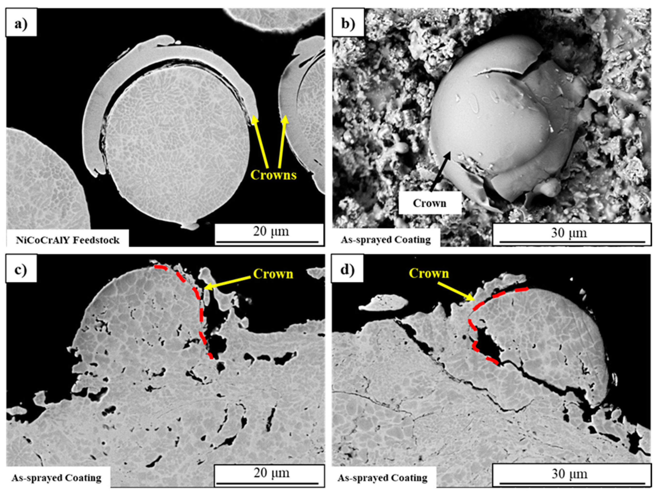
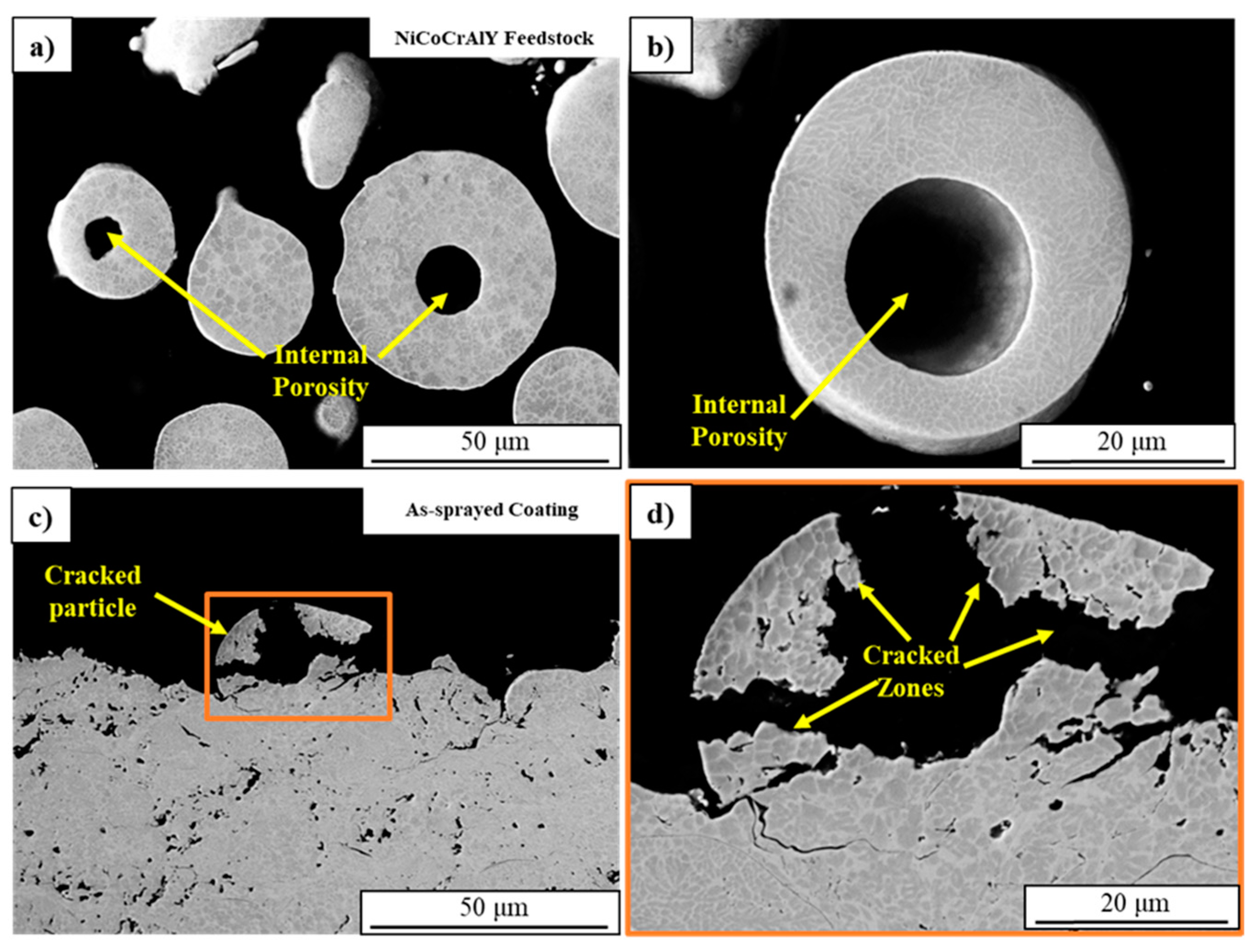
3.1. NiCoCrAlY Feedstock

Amdry 386-2.5, a commercially available powder with a cut size of −63 + 22 µm is designed for NiCoCrAlY bond coat applications. Characterization of this powder was conducted to analyze its morphology in relation to the deposited coatings. This feedstock characterization aided in revealing the microstructural features resulting from gas atomization and their influence on the coating microstructure, as well as the overall functional performance of the bond coat. Figure 2 represents the SEM-BSE images of the NiCoCrAlY powder, where the powder particles are shown in Figure 2a–c, while the related cross-sections are shown in Figure 2d–f, respectively. In Figure 2a–c, the powder particle morphology reveals the presence of spheroidal particles, elongated particles, and satellites attached to larger particles [13,14]. Satellites attached to the particles are usually singular in count but are not limited to this and can extend up to 2–3 particles [13,14]. Figure 2b highlights an elongated particle, typically a hybrid of dendritic and aggregate particles, attached to a particle which is larger in form and spheroidal in shape. The feedstock powder also features aggregates attached to the spheroidal particles, appearing as caps or circlets assigned to a particle, referred to as “crowns” in this study, as seen in Figure 2c. All these morphological features are attributed to the gas atomization technique employed in powder production [15,16]. It is well documented in previous studies that the presence of dendritic and/or aggregate particles leads to reduced apparent density and poor flowability, thereby influencing deposition efficiency [17].
Figure 2d reveals the cross-section of the powder particles and their internal features like porosity and phase distributions of the feedstock. The presence of porosity within the feedstock poses a significant hindrance to coatings, as the NiCoCrAlY feedstock material is expected to form a dense coating. This dense coating, in turn, is anticipated to restrict exposure to oxygen during service conditions. The presence of elevated porosity in the feedstock, when deposited using the HVAF process, a high-velocity, low-temperature technique, has the potential to propagate these porosity defects into the resulting coating, thereby contributing to an overall increase in the coating’s porosity. The limitation of porosity at the feedstock level is crucial, as it aids in minimizing the total porosity content. This, in turn, preserves the aluminum reservoir during the service life, contributing to the prolonged life of the TBCs and, consequently, the gas turbine system. Figure 2d represents spheroidal particles with internal porosity, typically resulting from gas-entrapped porosity during gas atomization in the presence of an inert gas, usually argon [18,19]. Figure 2e highlights the cross-section of an elongated particle and reveals grains and grain boundaries. A dark β-(Ni (Co)Al) phase in a continuous bright γ-(Co/Ni/Cr) matrix is also highlighted in Figure 2e [20]. This figure also illustrates the grain distribution within other spheroidal particle cross-sections, demonstrating a generally uniform arrangement. In some instances, elongated particles, typically formed by the aggregation of two particles, exhibit a necking or fused zone with uneven grain size distribution [5]. This distribution is attributed to the cooling stage after gas atomization, where the high temperature and pressure induce severe heating and rapid cooling cycles on the grain structures of powder particles, as observed in necking zones. Similarly, in Figure 2f, the crowns attached to the spheroidal particles reveal a bright γ-(Co/Ni/Cr) phase with minimal β-(Ni (Co)Al) distribution [5,21,22]. These discontinuous crown-shaped particles will cause splat boundaries, contributing to the coating porosity. These crown-shaped particles, exposed to the flame torch, may limit heat transfer to the internal particle. Consequently, within a high-velocity process like HVAF, the trajectory of such particles might lead to their transformation into partially molten particles within the coating system. These partially molten particles further contribute to porosity, which is an undesirable characteristic for a bond coat application.

3.2. Particle Diagnostics

AccuraSpray sensor was utilized to measure the average particle velocity and temperature of the feedstock powder, which are depicted in Figure 3. It is anticipated that low-pressure parameters would exhibit lower velocity compared to high-pressure parameters due to the disparity in the gas flow through the M3 system. A higher gas flow through the system results in a greater rush of particles expanding in the atmosphere within the spray booth. The AccuraSpray system validated this expectation, consistently showing lower average velocity for the low-pressure parameters. The temperature of the feedstock particles in the N1 and N2 nozzles remained approximately even at 1500 °C, while the N3 and N4 nozzles exhibited a 200 °C-higher temperature than the N1 and N2 nozzles. This temperature difference can be attributed to the nozzle dimensions, as indicated in Figure 1b. The N3 and N4 nozzles are 50 mm longer than the N1, and N2 nozzles, providing a longer travel time for the particles in the flame torch. This could result in an extended dwell time of the feedstock particles, leading to higher average particle temperature. It is noteworthy that the standard deviations in both average temperature and velocity in the N3 and N4 nozzles tend to be higher than in those of the N1 and N2 nozzles. Further investigations are required to determine the cause of these elevated deviation values.

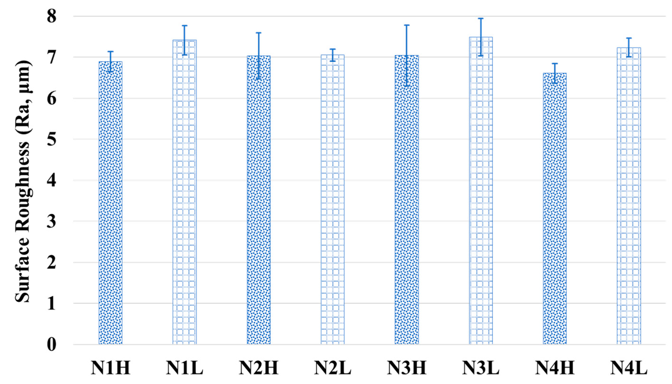
3.3. Topographical Analysis—Coatings

Figure 4 shows SEM-BSE images illustrating the topography of each sample, labeled according to their corresponding deposition parameters. The images in Figure 4 offer insights into various topographical features, encompassing partially molten particles and fully deformed splats, collectively shaping the entire coating system. These observations were consistently detected across all samples. Fully molten splats are dispersed across the coating surface, and the final particles ejected from the spray torch create a noticeable splash, as indicated by magenta-colored arrows in Figure 4. Similarly, partially molten particles could also be the constituents of the deposited coating system. However, the topographical representation, which includes partially molten particles, may not accurately represent the underlying particles, as they undergo impinging effects from the particles coming before them. Nevertheless, Figure 4 highlights the final layer of particles emerging from the spray torch, as indicated by yellow arrowheads.
It is evident from all the images that the presence of partially molten particles is apparent in all the coatings. The presence of partially molten particles can be attributed to limited exposure within the flame torch, causing them to adhere to the coating surface. Due to this restricted heat exposure, these particles undergo partial melting around their circumference, aiding their adhesion to the splats or the coating in general [23]. The presence of these partially molten particles is consistently observed throughout the coating system, with particle diameters exceeding 35 µm. The presence of these splats and their integration into the coating system could indicate the existence of splat boundaries, contributing to the porosity content in the coating. Such splat boundaries may act as diffusion zones, enabling oxygen to penetrate deeper into the bond coat and deplete the aluminum reservoir at an accelerated rate. The premature depletion of this aluminum reservoir could adversely affect the lifespan of the bond coat and, consequently, the entire TBC system. Increased porosity and diffusion zones are undesirable for bond coat applications because they accelerate oxidation and can increase residual stresses, making TBCs more susceptible to cracking under thermal cycling [23]. Therefore, addressing these issues based on a confined powder cut size holds potential. Further investigations are necessary to comprehensively understand these concerns, including detailed statistical analyses for validation. Furthermore, the measured surface roughness of these samples is in the range of 7 µm and follows the same trend for all the sample systems. Figure 5 represents the bar graph highlighting the average surface roughness with the standard deviations out of ten measurements in different orientations. The uniform surface roughness ensures consistent adhesion of the topcoat, enhancing bond strength, and reduces the risk of delamination. Nevertheless, excessively low roughness may compromise adhesion, while high roughness can generate stress concentration zones, resulting in crack propagations. Maintaining optimal roughness is ideal to ensure the durability of the TBC.

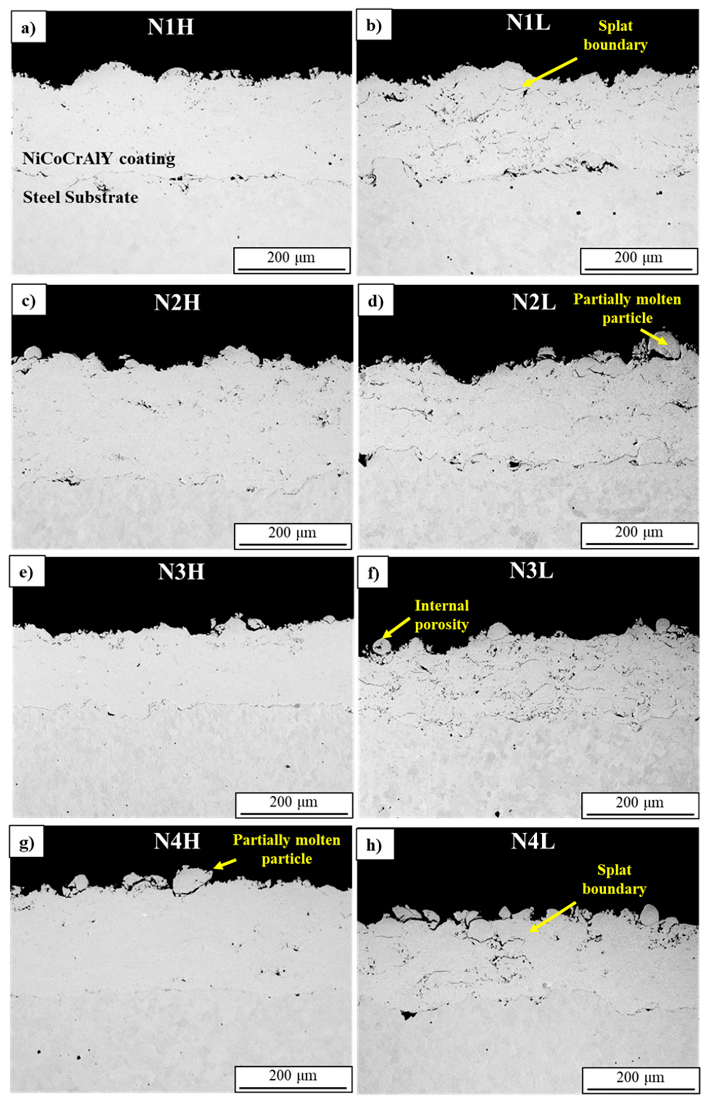
3.4. Microstructural Analysis—Coatings

The cross-sectional SEM-BSE images in Figure 6 illustrate the microstructural features of all coatings at 200× magnification, showcasing the NiCoCrAlY coating over the stainless-steel substrates. Notably, coatings deposited under high-pressure parameters, namely N1H, N2H, N3H, and N4H, exhibit a denser microstructure compared to those deposited under low-pressure parameters. The enhanced flow rates associated with high-pressure parameters likely led to improved fuel-rich conditions due to the enhanced flammable properties of the abundant gases. This observation aligns with the slightly higher temperature and velocity depositions seen in Figure 3 for high-pressure parameters. The synergistic effects of higher velocity deposition and improved temperature deposition under high-pressure parameters potentially induced a better peening effect within the powder particles [24]. This, in turn, may have contributed to further deformation and reduced porosity, resulting in a denser coating microstructure. The microstructural images of high-pressure parameter coatings (N1H, N2H, N3H, and N4H) are displayed in Figure 6a,c,e,g, respectively.
Conversely, coatings deposited under low-pressure parameters, such as N1L, N2L, N3L, and N4L, do not exhibit the same favorable characteristics for achieving high-density coatings. The effects of particle peening are less evident in these samples, possibly contributing to increased porosity, especially in terms of splat boundaries. As indicated in Figure 3, low-pressure parameters resulted in deposition velocities at least 50 m/s lower than their high-pressure counterparts (N1H, N2H, N3H, and N4H), with slightly lower-temperature deposition. The primary purpose of employing low-pressure parameters is to investigate the impact of in-flight particle oxidation on feedstock particles. This intentional variation in deposition parameters led to a comparatively porous coating microstructure in coatings deposited under low-pressure parameters, as shown in Figure 6b,d,f,h. In these coatings, the predominant source of porosity is identified at splat boundaries, primarily arising from insufficient or partial melting during the deposition process. The presence of partially molten particles serves as a clear indicator of inadequate melting, suggesting minimal in-flight particle oxidation due to limited melting or heat exposure. Unlike high-pressure parameters, the low-pressure parameter samples experienced reduced heat exposure, potentially preserving a higher aluminum content. However, it is essential to recognize that insufficient melting, even with reduced aluminum depletion, does not necessarily translate to an effective bond coat [25]. Achieving the optimal balance between particle melting, heat exposure, coating porosity, and other factors is crucial. Table 2 presents the coating thickness measurements of eight different HVAF-M3 samples. The thickness values range from 122.0 µm to 215.5 µm, with corresponding standard deviations indicating the variation within each sample group. The measured thickness was a result of deposition parameters, indicating the influence of nozzle configuration and air-fuel pressures process variables on the coating build-up. Higher deposition parameters, such as increased air-fuel pressures, likely contributed to thicker coatings, while lower pressures resulted in comparatively thinner layers.

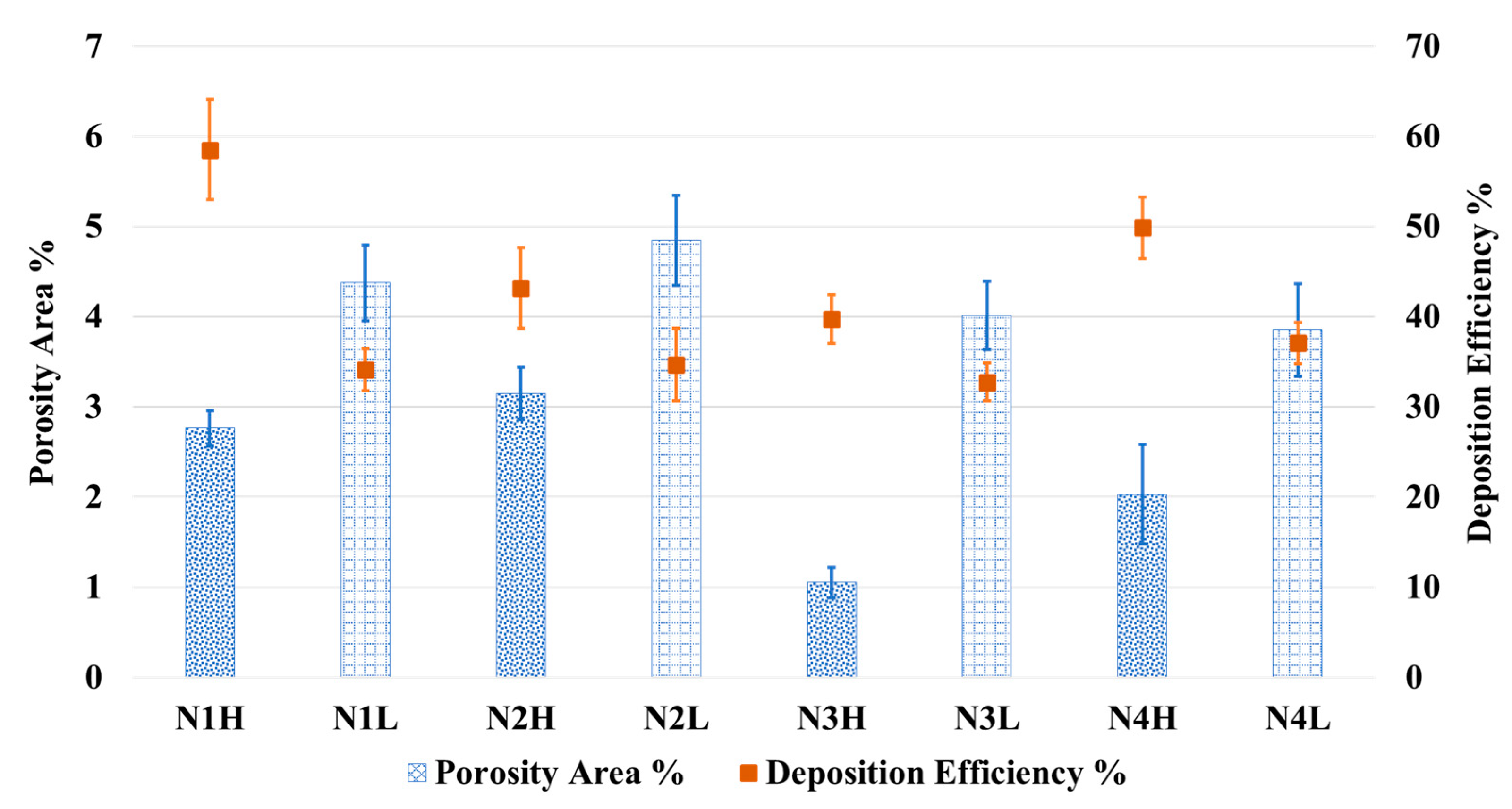
3.5. Porosity Analysis

All the coatings were studied for porosity area percentage using ImageJ software and are compared to deposition efficiency % in Figure 7. The high-pressure parameters resulted in a dense coating microstructure due to the peening effect, while the low-pressure parameters resulted in a porous microstructure. The discussion also stands the same among the nozzle types, as with the increased length of the nozzle in the N3 and N4 nozzles, the dwell time of the particles increased, leading to low porosity content. This increment could have melted the particles better, leading to a comparatively dense microstructure [21]. Among the high-pressure parameters, the N1 and N2 nozzles have slightly higher porosity area % than the N3 and N4 series nozzles; see Figure 7. Despite the insignificant variation, the difference should be accounted for in porosity-sensitive applications. The deposition efficiency is highest in the N1H deposition condition followed by the N4H condition. The combination of the N1 nozzle and the feedstock powder cut size likely contributed to the most suitable configuration, resulting in the highest deposition efficiency among all configurations. It is certainly clear among all the conditions that high-pressure parameters resulted in better deposition efficiency, while low-pressure parameters lagged as expected.

3.6. Inference on Feedstock and Coating Microstructure

In an alternative perspective, partially molten particles exhibit plastic deformation followed by subsequent rapid solidification, leaving distinctive splat boundaries. The existence of splat boundaries can also be linked to the crowns observed in the feedstock (Figure 2). This was also evident in one of the coating systems, as seen in Figure 8. Figure 8a highlights the cross-section of the crowns, where such deposited particles are shown on a coating in Figure 8b. These crowns are also observed in coating cross-sections, as seen in Figure 8c,d. These crown-based particles in the coatings tend to align together and promote their gaps as splat boundary-based porosity in a coating system. Also, the prevalence of splat boundaries is more pronounced in the low-pressure parameter samples compared to their high-pressure counterparts. In the high-pressure parameter systems, splat boundaries were observed away from the substrate–coating interface, suggesting a potential peening effect of particles over existing splats in the coating. These coatings, with prominent splat boundaries, may be considered for post-treatments such as heat treatment or hot isostatic pressing to address specific porosity features, offering new paths for future research and development. Apart from these observations, partially molten particles were also observed on the top of the coating systems, as seen in Figure 4. Fine porosity counterparts could be due to internal gas porosity, as seen in the feedstock powders (Figure 2d), also observed in Figure 6f.
Figure 9a,b depicts the cross-section of the NiCoCrAlY powder feedstock, highlighting internal porosity defects. These defects are attributed to inert gas entrapment during the feedstock production process, which must be minimized to reduce their impact on the coating’s density. Moreover, Figure 9c,d illustrate instances where such feedstock particles, upon deposition, resulted in cracking, thereby contributing to the overall porosity of the coating. The cracking observed in these particles during the HVAF process is likely a result of the unique combination of its high-velocity and low-temperature deposition conditions. HVAF minimizes in-flight particle oxidation due to the reduced thermal exposure compared to higher-temperature processes like HVOF and plasma spraying. However, this advantage may come at the cost of the observed cracking which might arise from insufficient thermal softening of particles during deposition, leading to inadequate accommodation of stresses at impact. This highlights the importance of optimizing deposition parameters to achieve a balance between particle heating, deformation, and coating density, regardless of the process employed. In contrast, processes like HVOF and plasma spraying operate at much higher temperatures, which can lead to significant in-flight oxidation. This oxidation can deplete aluminum in NiCoCrAlY feedstock particles, as aluminum readily reacts with oxygen to form alumina. Such aluminum consumption reduces the ability to form a continuous and protective alumina scale during service, potentially compromising the performance of the coating.

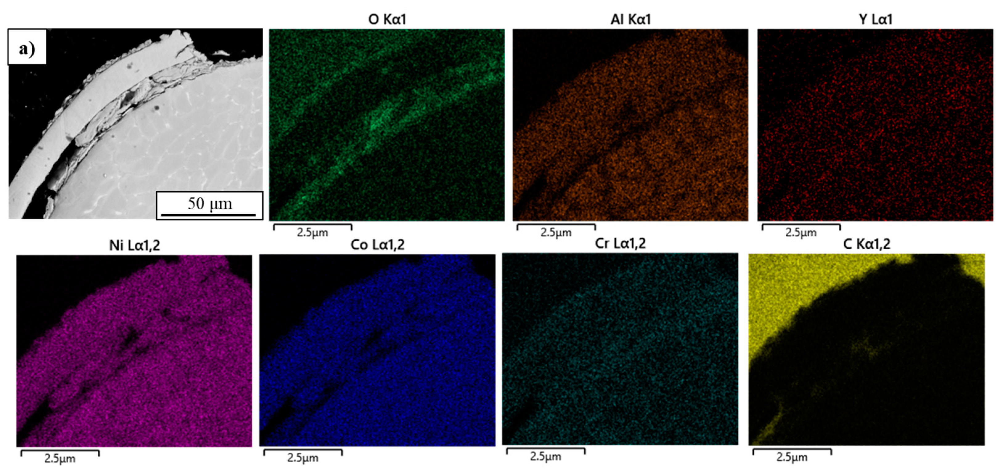
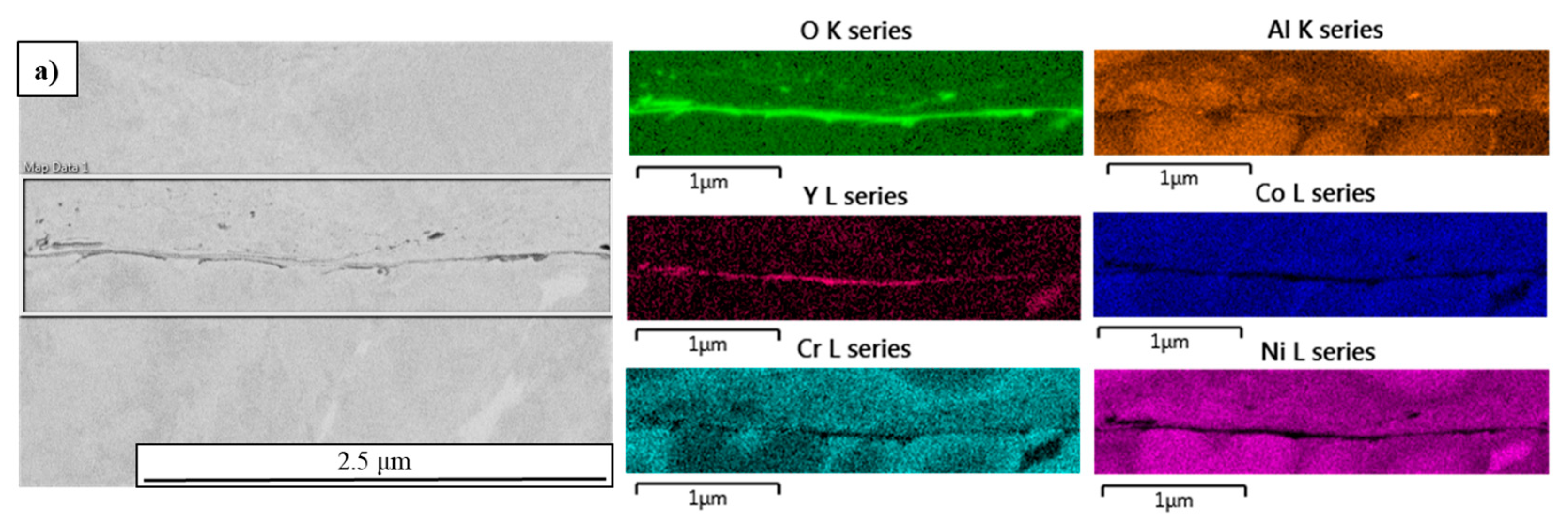
3.7. Compositional Analysis—Feedstock and Coating Microstructure

Figure 10 represents the cross-sectional image of a feedstock particle consisting of crowns attached to it. The EDS maps revealed the presence of oxygen, yttrium, and aluminum at the interface between the spherical particle and the crown. This interface also consists of NiCoCrAlY material composition with a very thin scale of yttria and alumina on the spherical particle. The observed oxide scale is continuous and closely adheres to the spherical particle, likely originating from oxidation during the gas atomization production process. In the gas atomization process, the melt pool of the NiCoCrAlY material is dispersed into fine droplets by a high-velocity gas stream, creating a large surface area exposed to ambient or inert gas environments. Despite the controlled atmospheres typically used in gas atomization, residual oxygen or impurities in the gas stream can react with yttrium, a highly reactive element in the alloy. The rapid heating and cooling rates can further contribute to the yttrium oxidation, due to its high affinity for oxygen, readily forming yttria. The composition of yttrium in the feedstock is very minimal, yet the very low Gibbs free energy of oxide formation compared to aluminum, nickel, or chromia makes it thermodynamically stable and highly favorable for oxidation at elevated temperatures. The diffusivity of yttria in the molten state is very high and ensures oxidation before aluminum. In multicomponent superalloy systems such as NiCoCrAlY, selective oxidation often occurs based on the relative thermodynamic stabilities of oxides. The thermodynamic stability of yttrium is very stable and thus preferentially forms as an oxide. Moreover, the yttrium oxides formed during the gas atomization process may have become encapsulated by crown-shaped splats on the particle surfaces, effectively retaining these oxides. These crown-shaped features, attached to the spherical particles, act as shields, preserving the oxides within. When such particles are deposited, the retained oxides are transferred onto the coatings, appearing in the coating microstructure and contributing to the overall oxidation content. Minimizing yttrium oxide formation requires strict control over the atomization atmosphere such as high-purity inert gases and equipment cleanliness to reduce oxygen contamination. Understanding and managing this phenomenon is critical for producing high-quality feedstock tailored for thermal spray processes like HVAF or HVOF.
Sample N3H exhibited the highest coating density among all samples, indicating a pronounced peening effect attributed to high-pressure parameters. This was characterized by the presence of well-deformed molten splats and a minimal number of partially molten particles. This distinct feature is particularly evident at the top of the coating, where Figure 11a highlights the presence of particles with internal gas porosity and partially molten particles at different magnifications. An EDS mapping analysis was conducted to discern any oxygen content attributed to in-flight particle oxidation. The mapping revealed minor traces of oxygen content, and the presence of yttrium and aluminum seemed to correlate with the location of oxygen pickup on the particle. The observed carbon content is associated with the low-viscosity epoxy mount used for sample characterization, and all other elements represent the fundamental material composition used in the feedstock for coating production. Although the oxide layer over a particle appears to be less than a micron thick, future advanced characterizations are planned to provide a more precise quantification. Despite the oxide content shown in Figure 11, the oxygen content is scarcely detected in the coating and may be at the nanoscale. The mapping presented in Figure 11 offers a comprehensive overview of oxygen content at various locations across different samples.
Sample N3L possesses an average porosity distribution among all the low-pressure parameter samples and contrasts with its counterpart, N3H, which exhibits a dense coating. The microstructure of N3L reveals the presence of partially molten particles and splat boundaries; see Figure 6. These features are attributed to the use of low-pressure parameters, which result in insufficient particle melting. Upon impact, such partially molten particles lack the velocity necessary to achieve dense packing, leading to the formation of partially molten particles leaving splat boundaries within the coating. Such an instance at the interface between particles was investigated in Figure 12. Figure 12a represents the elemental map of an interface between two particles within the coating system. It is observed that the interface between two particles consists of a thin continuous scale of yttrium, oxygen, and aluminum, which can be attributed to oxides formed during both gas atomization and HVAF deposition. This confirms the possibility of yttria or alumina scales developed from the deposit or carried from the feedstock and subsequently transferred into the coating during deposition. Additionally, while the HVAF process operates at relatively low temperatures, there is still potential for oxidation during particle flight or upon impact, particularly at splat boundaries where incomplete melting can occur. This dual contribution from feedstock oxidation and deposition-induced oxidation likely accounts for the observed oxide scale at the particle interfaces. Further investigations are necessary to distinguish oxides originating from the feedstock and those formed during the HVAF deposition process at the coating level. Nonetheless, this study serves as a fundamental insight to highlight and understand the formation and contribution of oxides in both scenarios.

4. Conclusions

Amdry 386-2, a commercially available NiCoCrAlY powder with a powder cut size of −63 + 22, was utilized in this study to investigate the impacts of deposition parameters using four different nozzle configurations provided by an HVAF-M3 system. Each nozzle configuration was tested with two deposition parameters, comprising high- and low-pressure parameters. The resulting coatings were examined concerning feedstock powder, coating microstructures, and any evidence of in-flight particle oxidation. The key findings are summarized as follows:
  • The morphology analysis of the feedstock powder exposed the existence of spheroidal particles, elongated particles, and satellites attached to larger particles. These morphological features exerted a significant influence on the coating microstructure, contributing to porosity in the form of splat boundaries and entrapped porosity, among other factors.
  • The utilization of four distinct nozzles, characterized by different lengths and exit diameters, had a notable impact on the coating microstructure, leading to varied velocities and temperatures during the deposition process. Specifically, high-pressure parameters induced higher velocities compared to their low-pressure counterparts, with temperature variations being relatively insignificant.
  • Within the four nozzle systems investigated, the N3 and N4 nozzles exhibited a slightly elevated temperature during deposition, while the velocity remained consistent. Among the coatings studied, N1H demonstrated superior deposition efficiency, with N4H following closely. Additionally, it was observed that, overall, high-pressure parameters yielded higher deposition efficiency and lower porosity compared to their low-pressure counterparts.
  • Among all the deposition parameters, N3H demonstrated the densest coating, followed by N4H. The enhanced particle dwell time due to the longer lengths of the N3, and N4 nozzles, combined with the high-pressure parameters, likely contributed to the improved peening effect and overall coating density in these systems.
  • Despite variations in nozzle configurations and deposition parameters, the surface roughness remained consistent across all sample systems.
  • Sample N3H highlights traces of oxygen content, associated with Y and Al, indicating potential in-flight particle oxidation.
Future research will focus on advanced characterization to comprehend feedstock powder oxidation resulting from powder manufacturing techniques and explore deposited coatings to understand in-flight particle oxidation. A thorough investigation of HVAF systems will be conducted, emphasizing NiCoCrAlY-based bond coat applications. This work serves as an initial foundation, paving the way for in-depth exploration in the future.

Author Contributions

Conceptualization, A.K.T., M.S.L., A.D. and C.M.; methodology, A.K.T., M.S.L., F.B.E., R.G., A.D. and C.M.; validation, A.K.T., M.S.L., R.G., A.D. and C.M.; formal analysis, A.K.T., M.S.L., R.G., A.D. and C.M.; investigation, A.K.T. and M.S.L.; data curation, A.K.T., M.S.L., R.C., S.B. and N.B.; writing—original draft preparation, A.K.T.; writing—review and editing, A.K.T., M.S.L., B.C.N.M.d.C., R.G., A.D. and C.M.; visualization, A.K.T., M.S.L., F.B.E., A.D. and C.M.; supervision, A.D. and C.M.; project administration, A.D. and C.M.; funding acquisition, A.D. and C.M. All authors have read and agreed to the published version of the manuscript.

Funding

This project was funded by the Consortium for Research and Innovation in Aerospace in Québec (CRIAQ), grant number APMC, and by the Natural Sciences and Engineering Research Council of Canada (NSERC), grant number ALLRP 556145-20.

Institutional Review Board Statement

Not applicable.

Informed Consent Statement

Not applicable.

Data Availability Statement

Data are contained within the article.

Acknowledgments

The authors also wish to thank Pratt and Whitney Canada, Pratt and Whitney USA and Tecnar Automation for their support with this project.

Conflicts of Interest

The authors declare no conflicts of interest.

Abbreviations

The following abbreviations are used in this manuscript:
HVAFHigh-Velocity Air-Fuel
HVOFHigh-Velocity Oxy-Fuel
APSAtmospheric Plasma Spray
TGOThermally Grown Oxide
FIBFocused Ion Beam
SEMScanning Electron Microscopy
FE-SEMField Emission—Scanning Electron Microscopy
EDSEnergy Dispersive Spectroscopy
TBCThermal Barrier Coating
GISGas Injection System
ASMEAmerican Society of Mechanical Engineers

References

  1. Thakare, J.G.; Pandey, C.; Mahapatra, M.M.; Mulik, R.S. Thermal Barrier Coatings—A State of the Art Review. Met. Mater. Int. 2020, 27, 1947–1968. [Google Scholar] [CrossRef]
  2. Hardwicke, C.U.; Lau, Y.-C. Advances in Thermal Spray Coatings for Gas Turbines and Energy Generation: A Review. J. Therm. Spray Technol. 2013, 22, 564–576. [Google Scholar] [CrossRef]
  3. He, J. Advanced MCrAlY alloys with doubled TBC lifetime. Surf. Coat. Technol. 2022, 448, 128931. [Google Scholar] [CrossRef]
  4. Yuan, K.; Peng, R.L.; Li, X.-H.; Johansson, S.; Wang, Y.-D. Some aspects of elemental behaviour in HVOF MCrAlY coatings in high-temperature oxidation. Surf. Coat. Technol. 2015, 261, 86–101. [Google Scholar] [CrossRef]
  5. Thoutam, A.; Lamana, M.; Mahdavi, A.; Liberati, A.; Ben Ettouil, F.; Moreau, C.; Dolatabadi, A. Influence of HVAF Process Parameters on In-Flight NiCoCrAlY Particle Oxidation and Corresponding Splat Characteristics. In Proceedings of the ITSC 2023, ASM International, Quebec City, QC, Canada, 22–25 May 2023; pp. 618–624. [Google Scholar]
  6. Chen, Y.; Zhao, X.; Bai, M.; Yang, L.; Li, C.; Wang, L.; Carr, J.; Xiao, P. A mechanistic understanding on rumpling of a NiCoCrAlY bond coat for thermal barrier coating applications. Acta Mater. 2017, 128, 31–42. [Google Scholar] [CrossRef]
  7. Toscano, J.; Vaβen, R.; Gil, A.; Subanovic, M.; Naumenko, D.; Singheiser, L.; Quadakkers, W. Parameters affecting TGO growth and adherence on MCrAlY-bond coats for TBC’s. Surf. Coat. Technol. 2006, 201, 3906–3910. [Google Scholar] [CrossRef]
  8. Browning, J.A. Viewing the future of high-velocity oxyfuel (HVOF) and high-velocity air fuel (HVAF) thermal spraying. J. Therm. Spray Technol. 1999, 8, 351. [Google Scholar]
  9. Sadeghimeresht, E.; Markocsan, N.; Nylén, P. A Comparative Study on Ni-Based Coatings Prepared by HVAF, HVOF, and APS Methods for Corrosion Protection Applications. J. Therm. Spray Technol. 2016, 25, 1604–1616. [Google Scholar] [CrossRef]
  10. Khamsepour, P.; Moreau, C.; Dolatabadi, A. Effect of Particle and Substrate Pre-heating on the Oxide Layer and Material Jet Formation in Solid-State Spray Deposition: A Numerical Study. J. Therm. Spray Technol. 2023, 32, 1153–1166. [Google Scholar] [CrossRef]
  11. Alroy, R.J.; Pandey, R.; Kamaraj, M.; Sivakumar, G. Role of process parameters on microstructure, mechanical properties and erosion performance of HVAF sprayed Cr3C2-NiCr coatings. Surf. Coat. Technol. 2022, 449, 128941. [Google Scholar] [CrossRef]
  12. Torkashvand, K.; Gupta, M.; Björklund, S.; Marra, F.; Baiamonte, L.; Joshi, S. Influence of nozzle configuration and particle size on characteristics and sliding wear behaviour of HVAF-sprayed WC-CoCr coatings. Surf. Coat. Technol. 2021, 423, 127585. [Google Scholar] [CrossRef]
  13. Zhang, L.-C.; Xu, W.-Y.; Li, Z.; Zheng, L.; Liu, Y.-F.; Zhang, G.-Q. Mechanism of rapidly solidified satellites formation in gas atomized powders: Simulation and characterization. Powder Technol. 2023, 418, 118162. [Google Scholar] [CrossRef]
  14. Dunkley, J.J.; Telford, B. Control of “Satellite” Particles in Gas Atomisation. Adv. Powder Metall. Part. Mater. 2002, 103–110. [Google Scholar]
  15. Anderson, I.E.; Figliola, R.S.; Morton, H. Flow mechanisms in high pressure gas atomization. Mater. Sci. Eng. A 1991, 148, 101–114. [Google Scholar] [CrossRef]
  16. Unal, R. Experimental and numerical modeling of the gas atomization nozzle for gas flow behavior. Comput. Fluids 2011, 42, 37–43. [Google Scholar]
  17. Beckers, D.; Ellendt, N.; Fritsching, U.; Uhlenwinkel, V. Impact of process flow conditions on particle morphology in metal powder production via gas atomization. Adv. Powder Technol. 2020, 31, 300–311. [Google Scholar] [CrossRef]
  18. Chen, G.; Zhou, Q.; Zhao, S.; Yin, J.; Tan, P.; Li, Z.; Ge, Y.; Wang, J.; Tang, H. A pore morphological study of gas-atomized Ti-6Al-4V powders by scanning electron microscopy and synchrotron X-ray computed tomography. Powder Technol. 2018, 330, 425–430. [Google Scholar] [CrossRef]
  19. Gerling, R.; Leitgeb, R.; Schimansky, F.-P. Porosity and argon concentration in gas atomized γ-TiAl powder and hot isostatically pressed compacts. Mater. Sci. Eng. A 1998, 252, 239–247. [Google Scholar] [CrossRef]
  20. Fritscher, K.; Lee, Y. Investigation of an as-sprayed NiCoCrAIY overlay coating—Microstructure and evolution of the coating. Mater. Corros. 2005, 56, 5–14. [Google Scholar] [CrossRef]
  21. Huang, J.; Sun, W.; Chu, X.; Lan, H.; Xie, Y.; Ye, D.; Huang, R. Effect of high temperature exposure on microstructure, mechanical and tribological properties of cold sprayed NiCoCrAlTaY coatings. Surf. Coat. Technol. 2023, 462, 129466. [Google Scholar] [CrossRef]
  22. Baufeld, B.; Schmücker, M. Microstructural evolution of a NiCoCrAlY coating on an IN100 substrate. Surf. Coat. Technol. 2005, 199, 49–56. [Google Scholar] [CrossRef]
  23. Hao, E.; Chen, J.; Liu, G.; Cui, L.; Jia, L.; Wei, L.; Ma, B.; An, Y. Effect of alloying elements on microstructure evolution and wear mechanism of MCrAlX-based coatings at 800 °C. Surf. Coat. Technol. 2023, 456, 129266. [Google Scholar] [CrossRef]
  24. Prashar, G.; Vasudev, H. A comprehensive review on combating the elevated-temperature surface degradation by MCrAlX Coatings. Surf. Rev. Lett. 2023, 30, 2330009. [Google Scholar] [CrossRef]
  25. Gupta, M.; Markocsan, N.; Li, X.-H.; Östergren, L. Influence of bondcoat spray process on lifetime of suspension plasma-sprayed thermal barrier coatings. J. Therm. Spray Technol. 2018, 27, 84–97. [Google Scholar] [CrossRef]
Figure 1. (a) M3 gun set up on a FANUC robotic arm. (b) Four nozzles of a M3 gun and their 2D cross-sectional view.
Coatings 15 00355 g001
Figure 2. SEM-BSE images of NiCoCrAlY feedstock particle morphology (ac) and their cross-sections (df).
Coatings 15 00355 g002
Figure 3. AccuraSpray plot for average particle velocity (m/s) and temperature (°C) for all the deposition parameters.
Coatings 15 00355 g003
Figure 4. SEM-BSE topographical images of all the coatings: (a) N1H, (b) N1L, (c) N2H, (d) N2L, (e) N3H, (f) N3L, (g) N4H, and (h) N4L.
Coatings 15 00355 g004
Figure 5. Arithmetic surface area roughness (Ra, µm) plot of all sample systems.
Coatings 15 00355 g005
Figure 6. SEM-BSE cross-sectional images of all the coating systems (a) N1H, (b) N1L, (c) N2H, (d) N2L, (e) N3H, (f) N3L, (g) N4H, and (h) N4L.
Coatings 15 00355 g006
Figure 7. Comparative plot between porosity area (bar graph) and deposition efficiency (line graph).
Coatings 15 00355 g007
Figure 8. (a) Crowns cross-section observed in the feedstock powder, (b) Crown topography observed on the coating. (c,d) Impact of crowns on the coating formation observed from a cross-sectional point of view at two different locations. Red dashed line confirms the interface of a crown attached to a particle.
Coatings 15 00355 g008
Figure 9. (a,b) NiCoCrAlY powder feedstock cross-section representing internal porosity. (c,d) Deposited particle–coating cross-section, revealing the impacts of high-velocity deposition from the HVAF process.
Coatings 15 00355 g009
Figure 10. (a) Feedstock powder cross-section, showing crowns attached to the particle, is represented using a SEM-BSE image at 5000× magnification. Color palettes represent the EDS elemental mapping highlighted next to the SEM image.
Coatings 15 00355 g010
Figure 11. (a) N3H coating cross-section highlighting internal porosity and a partially molten particle is represented using a SEM-BSE image at 5000× magnification. Color palettes represent the EDS elemental mapping highlighted next to the SEM image.
Coatings 15 00355 g011
Figure 12. (a) Electron image of a N3L sample highlighting an interface between two particles within the coating system is represented using a SEM-BSE image at 20,000× magnification. Respective elemental maps.
Coatings 15 00355 g012
Table 1. HVAF-M3 torch deposition parameters.
ParametersAll Nozzles
(N1H, N2H, N3H, N4H)
All Nozzles
(N1L, N2L, N3L, N4L)
Powder Feed Rate (g/min)100100
Powder Carrier Gas (L/min)4545
Stand-off distance (mm)300300
Air Pressure (MPa)0.70.6
Fuel 1 Pressure (MPa)0.60.5
Fuel 2 Pressure (MPa)0.60.5
No. of Passes44
Powder Cut Size (µm)−63 + 22−63 + 22
Table 2. Eight HVAF-M3 deposited sample coating thickness (µm).
Sample Type/NameThickness (µm)
N1H215.5 ± 15.2
N1L152.0 ± 5.7
N2H188.3 ± 14.6
N2L163.8 ± 14.4
N3H149.5 ± 12.0
N3L125.3 ± 12.5
N4H151.3 ± 17.5
N4L122.0 ± 7.5
Disclaimer/Publisher’s Note: The statements, opinions and data contained in all publications are solely those of the individual author(s) and contributor(s) and not of MDPI and/or the editor(s). MDPI and/or the editor(s) disclaim responsibility for any injury to people or property resulting from any ideas, methods, instructions or products referred to in the content.

