Article

Enhancing the Wear Resistance of CrAlN-Coated Tools in Milling and Turning Through Annealing with Optimized Duration

by
Georgios Skordaris
1,
Dimitrios Tsakalidis
1,
Konstantinos-Dionysios Bouzakis
1,*,
Fani Stergioudi
2 and
Antonios Bouzakis
3
1
Laboratory for Machine Tools and Manufacturing Engineering, School of Mechanical Engineering, Aristotle University of Thessaloniki, 54124 Thessaloniki, Greece
2
Physical Metallurgy Laboratory, School of Mechanical Engineering, Aristotle University of Thessaloniki, 54124 Thessaloniki, Greece
3
Impact-BZ, London SW11 5QL, UK
*
Author to whom correspondence should be addressed.
Coatings 2025, 15(3), 311; https://doi.org/10.3390/coatings15030311
Submission received: 3 February 2025 / Revised: 27 February 2025 / Accepted: 1 March 2025 / Published: 7 March 2025
(This article belongs to the Section Surface Characterization, Deposition and Modification)

Abstract

:
The work aimed to investigate the possibility of improving the mechanical properties, and therefore the wear resistance, of coated tools in manufacturing processes with continuous or interrupted cutting loads through appropriate annealing. In this context, PVD CrAlN coatings were deposited on cemented carbide inserts. A part of these coated tools was annealed at a temperature of 400 °C, which was close to the deposition temperature, in an inert gas atmosphere. The annealing duration ranged up to 60 min. Nanoindentations and repeated perpendicular and inclined impact tests were carried out to characterize the strength, fatigue, and adhesion of the tool coatings before and after annealing. According to the results, the mechanical properties of the coating and the fatigue resistance were maximized after a short annealing period of about 15 min, while the adhesion of the coating remained unchanged. These facts led to a large increase in tool life in milling 42CrMo4 QT, when annealed coated tools were applied at 400 °C for 15 min. Furthermore, turning experiments using the mentioned hardened steel as well as GG30 cast iron to produce continuous or interrupted chips, respectively, confirmed the obtained results in milling. Therefore, annealing of coated cutting tools at an optimized duration is recommended as an effective method to extend tool life.

1. Introduction

Physical vapor deposition (PVD) encompasses a wide range of vacuum coating techniques in which material is physically removed from a source by evaporation or sputtering [1]. The ability of PVD to precisely control the thickness of the coating on tool surfaces ensures a sharp cutting edge. In addition, PVD offers valuable properties, such as high inherent hardness and compressive strength, which help prevent crack propagation in the coating and the tool material. As a result, PVD coatings are increasingly being adopted in cutting applications [2,3,4,5,6]. The increasing demands on modern manufacturing processes have led to significant innovations in coatings, tool materials, tool geometries, and deposition process conditions [7,8,9]. Furthermore, performing post-treatments on coated tools, such as micro blasting and annealing, have been documented as powerful tools for extending the life of the coated tool [10,11,12,13,14]. The annealing process for coated tools has a significant impact on the film hardness and fatigue strength. However, there is a temperature limit that must be maintained. Research shows that when the annealing temperature exceeds 400 °C, there is a noticeable decrease in the film hardness and elastic modulus [15,16].
In this context, a short annealing period close to the deposition temperature has been shown to be an effective method to improve the cutting performance of TiAlN films [17]. At this temperature, based on the non-equilibrium phase diagram of the TiN-AlN system and its chemical composition, no phase transformations or separations occur during isothermal annealing [18]. However, changes in the hardness and strength of the coating occur, driven by atomic migrations and dislocation motions [19,20]. These changes depend, among other factors, on the annealing duration and the coating thickness and its chemical composition. Such dependencies in the case of TiAlN PVD coatings were described in [17].
CrAlN coatings have been developed with more stable thermal behavior compared to TiAlN coatings [3]. We investigated the possibility of enhancing the wear resistance of CrAlN-coated tools used in manufacturing processes subject to continuous or interrupted cutting loads by means of appropriate annealing times close to the deposition temperature. Relevant results for CrAlN coatings have not yet been published.
The wear mechanisms in cutting with coated tools depend on the process kinematics and, among other factors, on the type of chips formed (continuous or discontinuous), which affect the peak loads. In interrupted cutting processes, the dynamic peak loads increase, affecting the wear of the coated tool, which is mainly influenced by the speed-dependent stress, strain, and fatigue strength of the coating [21]. In continuous cutting kinematics, the wear resistance of annealed coatings is mainly associated with the subsequent changes in their mechanical properties and hardness. The present study introduces the beneficial effects of annealing on tool life in both interrupted and continuous cutting processes. For this purpose, milling experiments were carried out for dynamic peak loads with continuous chip formation using hardened 42CrMo4 QT steel. In addition, turning investigations with continuous or discontinuous chips were carried out with the application of the mentioned hardened steel and GG30 cast iron, respectively. The improvement in tool life was correlated with the observed coating strength, fatigue strength, and adhesion developed after various annealing durations.

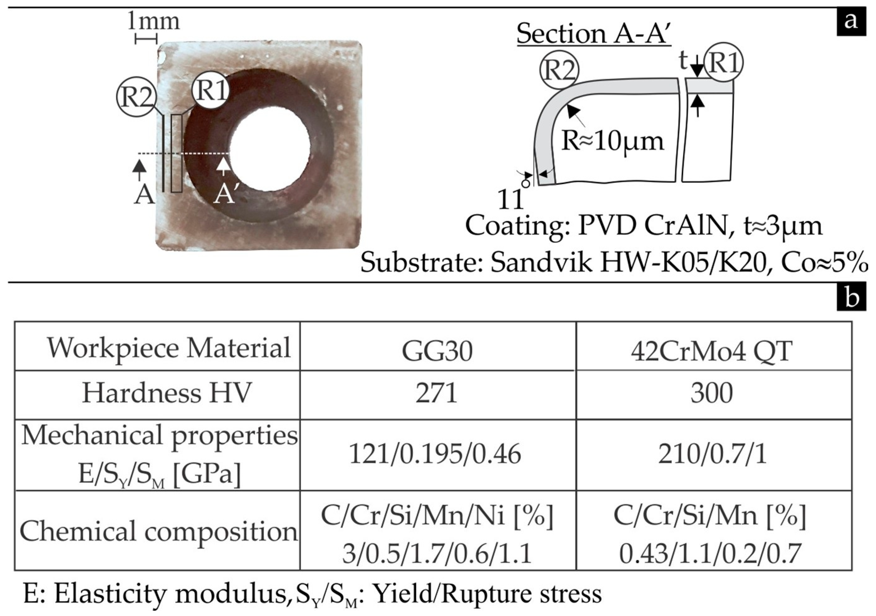
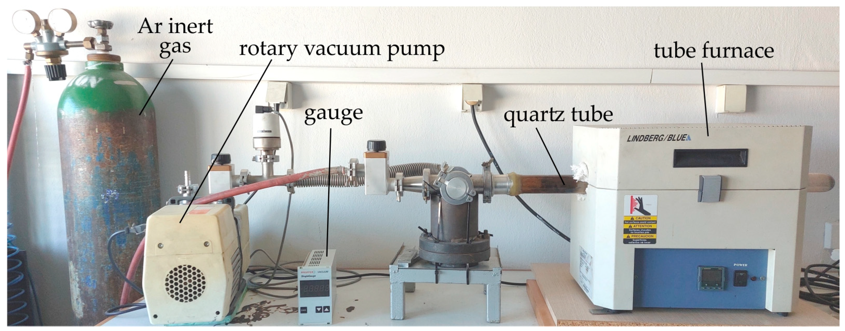
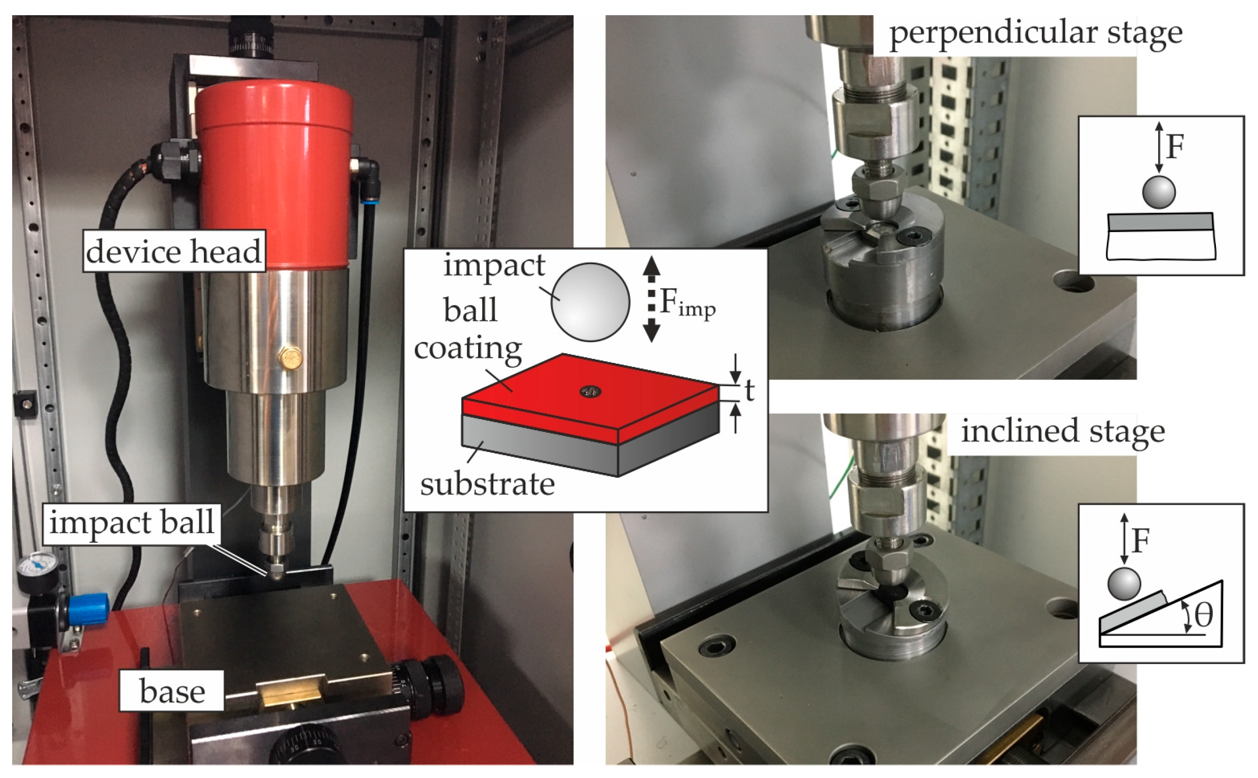
2. Materials and Methods

In the investigations carried out, a PVD CrAlN coating was used. This was deposited on HW-K05/K20 cemented carbide inserts with a thickness of approximately 3 μm. The thickness of the coating was measured by conducting crater ball tests. The WC-Co microstructure was classified as fine, with WC grain sizes ranging from 1.0 to 1.3 μm. The geometry of the cutting inserts used is shown in Figure 1a. The tip roundness of the coated tools was captured by confocal measurements along the tool edge according to the methodology described in [3]. Successive cross-sections of the cutting edges were monitored, and the corresponding tool wedge radii of the tip roundness were estimated. In the milling investigations carried out, hardened 42CrMo4 QT steel was applied. The latest steel and GG30 cast iron were used in turning, to quasi-statically and dynamically load the cutting edge due to continuous and discontinuous chip formation, respectively. Figure 1b shows the main mechanical properties and chemical composition of the workpiece materials. The mechanical properties of the workpiece materials used were determined by conducting tensile tests. EDX analyses were performed to study the chemical composition of the workpiece materials applied. Portions of the coated tools were annealed under vacuum for 5 min, 15 min, 30 min, and 60 min. The annealing temperature was kept constant at 400 °C in all cases. The latter temperature was close to the coating deposition temperature of 450 °C.
The milling and turning experiments were carried out using a John Ford VMC-850 CNC machining center (JohnFord Roundtop Machinery Industries Co. Ltd., Taichung City 42952, Taiwan)and a Chevalier CNC Lathe FCL-1840 (Falcon Machine Tools Co. Ltd., Chang Hua 509004, Taiwan), respectively. Cutting conditions, such as cutting speed, feed rate, and depth of cut, were kept constant. The developed stress fields in the coated cutting edges were determined using the ANSYS FEM software package (ANSYS 2024R1).
For annealing the coated inserts, a medium vacuum apparatus was used. This was capable of performing heating in a controlled environment, either under an inert gas atmosphere or under vacuum conditions, with the vacuum reaching approximately 10−2 mbar. The components of this apparatus are illustrated in Figure 2. Samples are placed inside a quartz tube, which is placed inside the horizontal tube furnace (Thermo Scientific Lindberg/Blue M TF55035C, Dublin, Ireland). The quartz tube is connected to a vacuum pump (Alcatel, Adixen 2010SD Pascal Dual Stage Rotary Vacuum Pump, Annecy, France) via suitable fittings, which ensure vacuum conditions by evacuating atmospheric air from the tube. Sealing the joints between the various components is achieved by using O-rings, placed between the mating surfaces, with clamps securing the connections. An inert gas, such as argon, is supplied through a dedicated connection to enable heat treatment in an inert gas atmosphere and to fill the tube with inert gas after evacuation. The applied manometer (Pfeiffer Vacuum, TPG 261, Annecy, France) displays the pressure inside the quartz tube, providing real-time monitoring during the process.
Nano-indentations were performed using a FISCHER SCOPE H100 device (Helmut Fischer GmbH, Sindelfingen, Germany), combined with FEM-supported calculations, to evaluate the mechanical properties of the coating and the substrate subjected to different annealing times [3]. To investigate the effect of the latter factor on the fatigue strength of the coated tools, perpendicular impact tests were performed [3]. The device used was developed by Impact-BZ (London, UK) in collaboration with the Laboratory for Machine Tools and Manufacturing Engineering at the Aristotle University of Thessaloniki (see Figure 3) [22]. The test setup included a 5 mm diameter cemented carbide ball repeatedly penetrating the sample under a customized maximum load. A proportional-integral-derivative (PID) controller regulated the output voltage of a variable transformer through a direct current (DC) motor to maintain constant impact force peaks throughout the test process. In addition, current, force, temperature, and other process variables were measured and closely monitored. In addition, using the same apparatus with a suitable coated sample fixture, the adhesion of the films was characterized by an inclined impact test [3,22]. The inclined impact test, conducted with the appropriate fixture shown in Figure 3, applies an oblique loading direction that introduces shear stress at the coating–substrate interface. In cases of poor adhesion, this leads to overloading of the interface and subsequent accelerated coating failure [3,22]. The resulting impact imprints were analyzed using three-dimensional measurements performed by the μSURF confocal microscope from NANOFOCUS AG (Oberhausen, Germany).

3. Results and Discussion

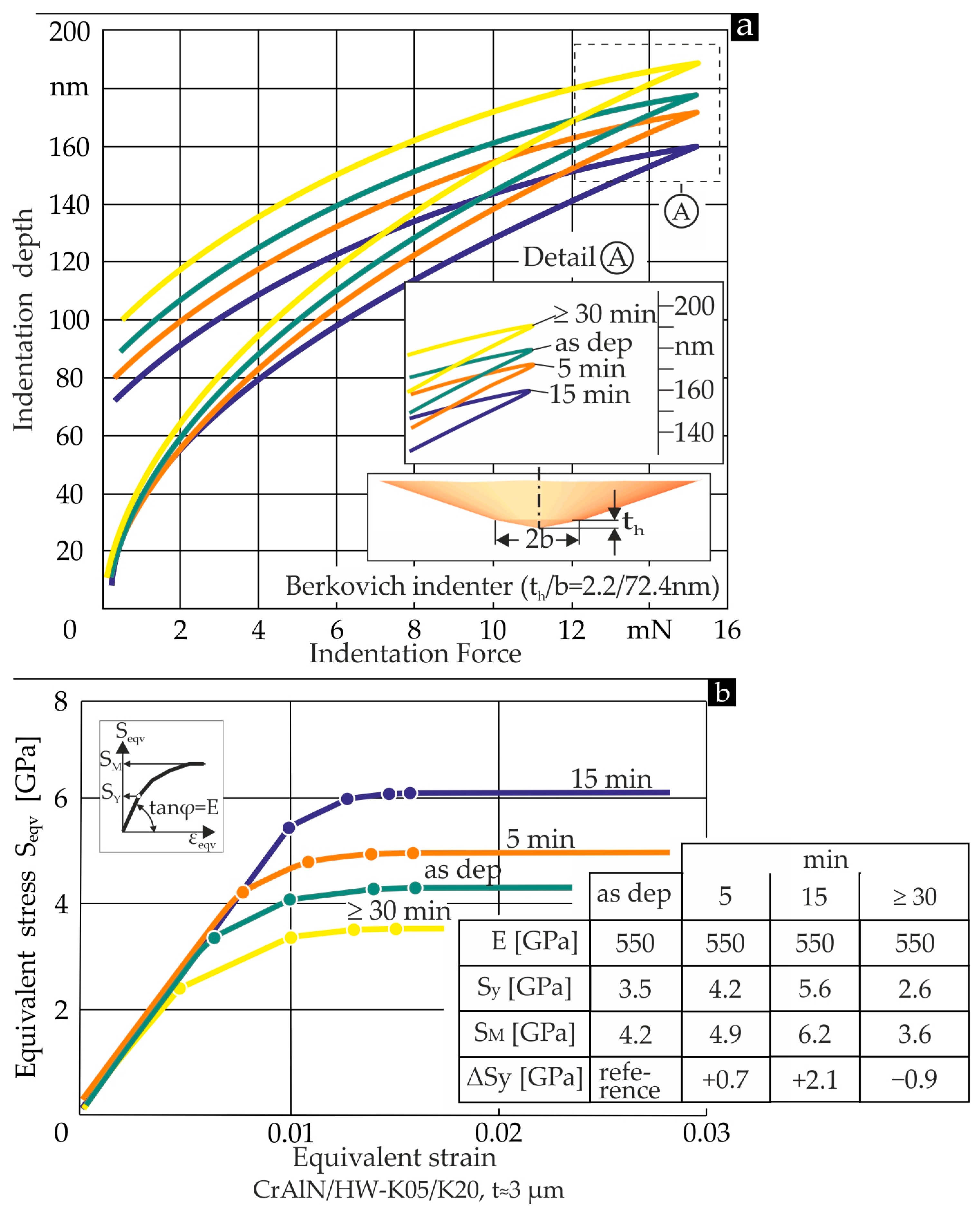
3.1. Determination of Coating’s Mechanical Properties Before and After Annealing

To evaluate the mechanical properties of the coatings before and after annealing, nanoindentations were performed on PVD-coated inserts under a maximum load of 15 mN. In particular, the low indentation load ensured that the substrate did not affect the indentation process, allowing for an accurate determination of the coating hardness [3]. The load-displacement diagrams for all coating cases investigated are shown in Figure 4a. There was a decreasing trend of the maximum achieved indentation depths up to an annealing time of 15 min. The reduced indentation depth was associated with an improvement in the hardness of the coating. Longer annealing times than 15 min resulted in an increase in the maximum indentation depth and, consequently, a degradation in the film hardness. Here, it is assumed that the specified hardness in each annealing case remained practically constant with respect to the coating thickness. This was due to the small coating thickness of 3 μm, as described in [17]. These trends can be explained by considering the effect on the film hardness of atomic migrations and dislocation displacements up to the grain boundaries [3,17,18]. In this way, the residual stresses of the coating and, consequently, the strength of its structure change, as described below.
To determine the stress–strain characteristics of the coatings, the nanoindentation data were analyzed using the experimental and computational approaches described in [3]. According to the results presented in Figure 4b, the modulus of elasticity remained constant in all annealing cases, while the yield and fracture toughness depended on the annealing duration. It should be noted that the mechanical properties of the substrate remain constant after annealing at a temperature of 400 °C and up to an annealing time of 60 min, according to previous research. Furthermore, the changes in the residual stresses of the coating annealed at various long-term levels related to the as-deposited coating are presented in the table in Figure 4b. In each annealing case, these were equal to the difference between the actual yield stress and that of the as-deposited coating [3]. It is worth noting that the increasing residual stresses to 2.1 GPa after an annealing time of 15 min compress the structure of the coating. The latter is decompressed at an annealing duration of 30 min compared to that of the as-deposited coating due to the decrease in the residual stress to −0.9 GPa.
As mentioned above, the hardness of the coating remained unchanged with respect to its thickness. Therefore, the calculated stress–strain curves in Figure 4b shown are valid for the entire thickness of the coating. This fact was taken into account in the FEM calculation of the coating deformation during cutting in Section 3.3.3.

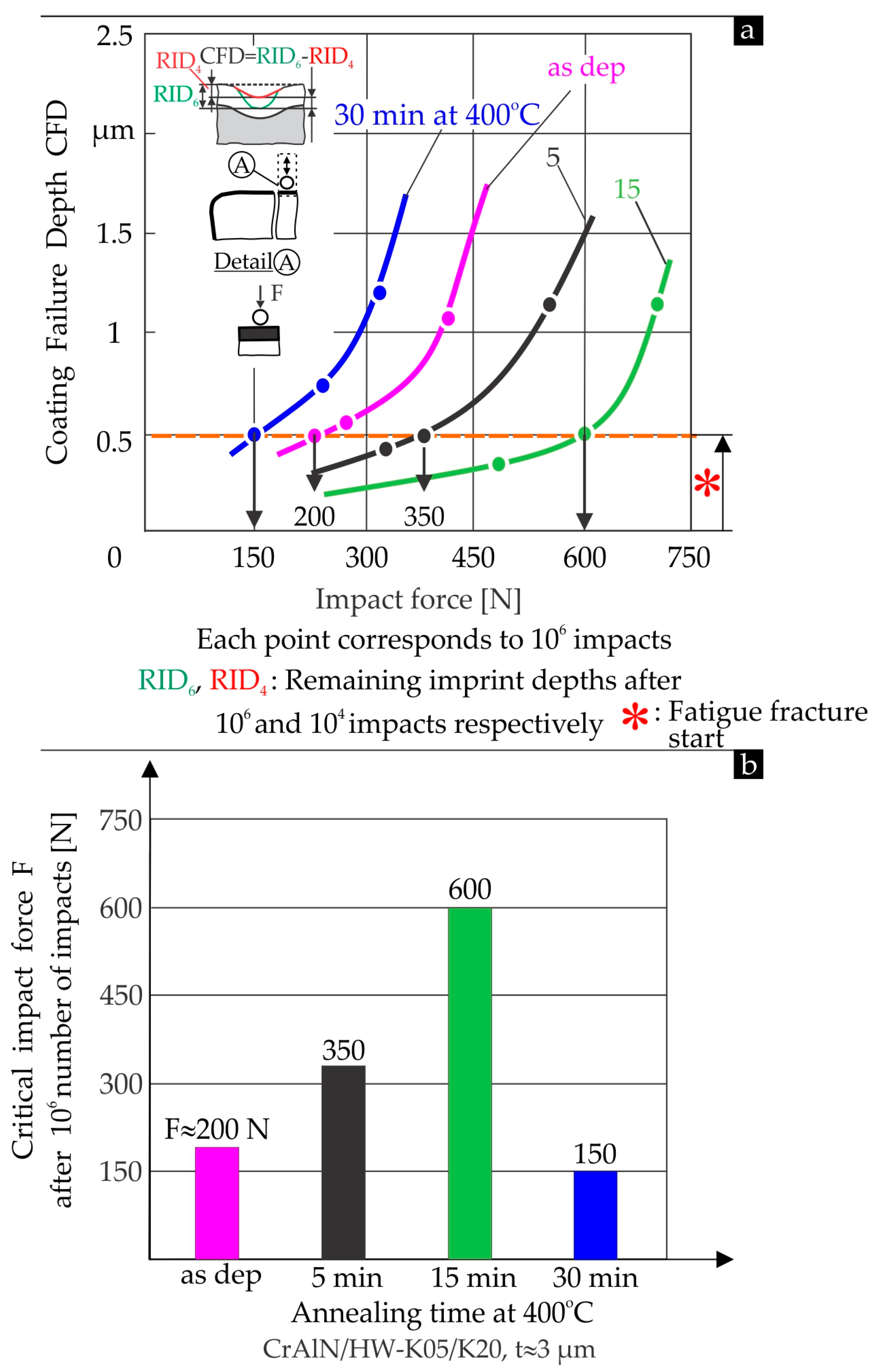
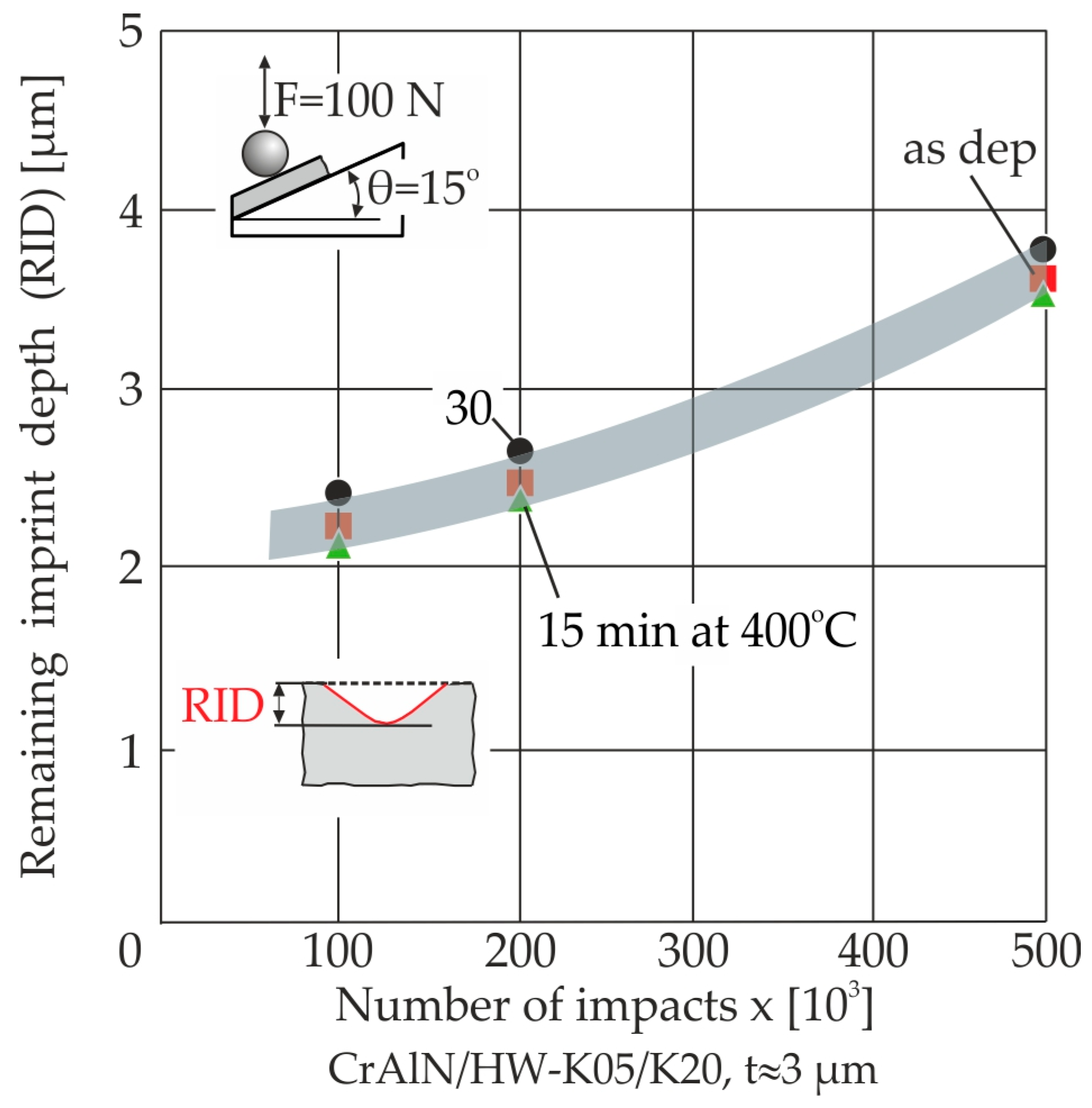
3.2. Characterization of the Fatigue Strength and Adhesion of Coatings After PVD Deposition and Annealing at Different Time Periods

To evaluate the effect of annealing on the fatigue failure of the film, perpendicular impact tests were performed on the coated inserts at different force levels (see Figure 5a). The coating fatigue fracture after one million impacts was quantified using the coating failure depth (CFD), which corresponded to the difference between the residual imprint depths after 104 (RID4) and 106 (RID6) impacts. RID4 depended on the impact load and was attributed only to the residual plastic deformation of the substrate. This was because no wear or fatigue failure was observed on the coated surfaces in all impact tests after 104 impacts.
The curves in Figure 5a represent the coating failure depth CFD plotted against impact force. A CFD of 0.5 μm after one million impacts was associated with the onset of coating fatigue failure. According to the results, the critical impact load F for the initiation of coating fatigue failure increased significantly from 200 N to approximately 600 N after an annealing time of 15 min, as also shown in Figure 5b. Longer annealing times, for example 30 min, limited the critical impact force due to the deterioration of the coating mechanical and fatigue properties mentioned earlier.
The inclined impact test was applied to evaluate the adhesion of coated tools after annealing [22]. In this test, the coated surface of the specimen was inclined to the impact force. In this way, high shear stress developed at the coating–substrate interface, thus initiating rapid coating failure in this area. This failure was the dominant factor for the subsequent increase in the remaining imprint depth. This depended on the extent of possible deterioration of the coating adhesion, for example, due to improper pre- or post-treatment of the coated tool. The remaining imprint depth versus the number of inclined repeated impacts in all cases of coating annealing is depicted in Figure 6. In these experiments, the impact force F was unchanged and equal to 100 N. The course of the residual imprint depth in relation to the number of impacts was practically unaffected by the annealing duration. Here, the shear stress that developed at the coating–substrate interface was the dominant factor in the failure of the coating and, therefore, in the remaining imprint depth. Since the latter factor was not affected by the annealing time but only by the number of impacts, it can be concluded that the coating–substrate interaction, i.e., the adhesion of the coating, did not depend on the annealing duration. However, the coating strength and fatigue properties were significantly affected, as already described.

3.3. Evaluation of the Cutting Performance of Coated Tools Before and After Various Long Annealing

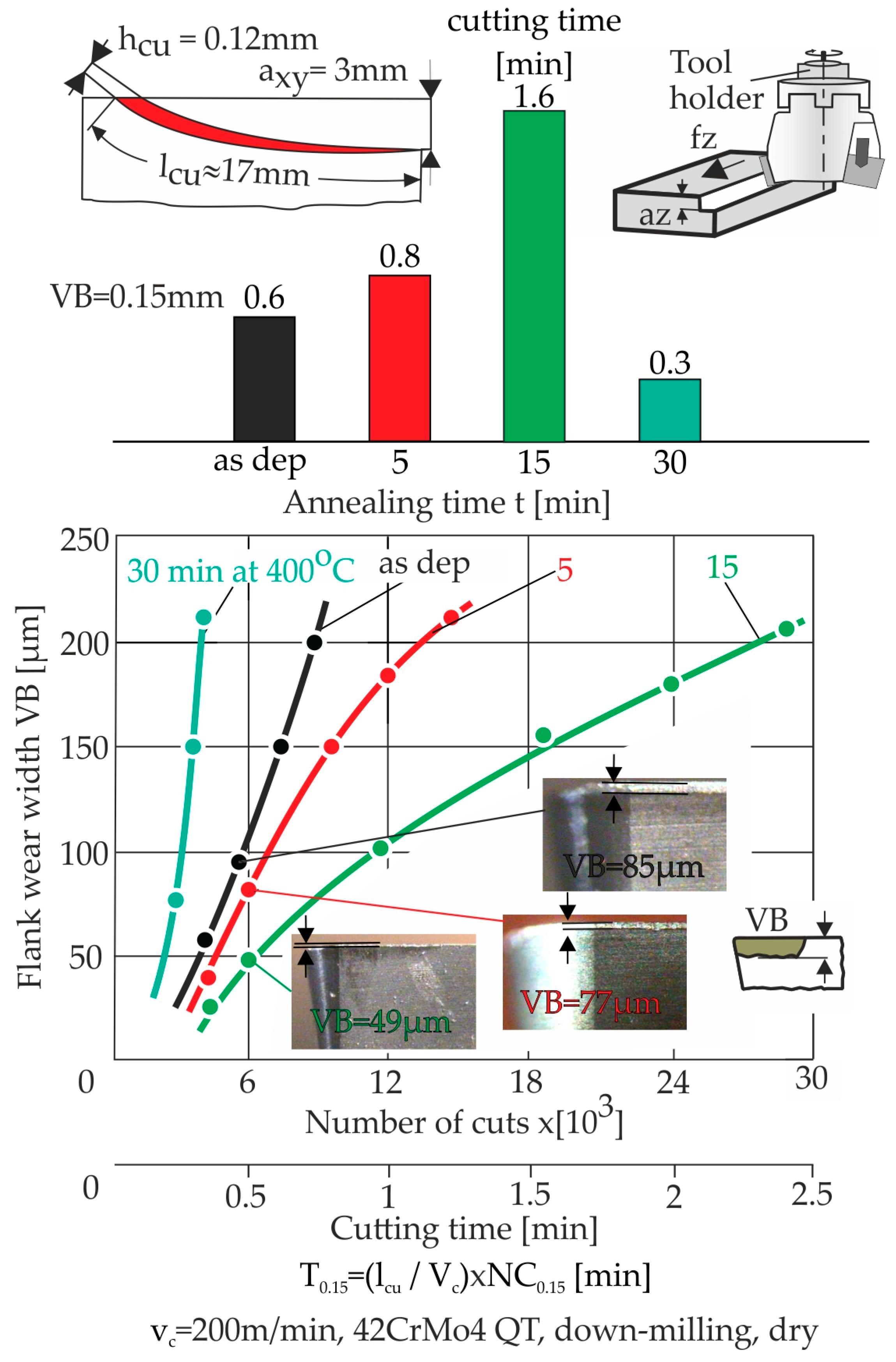
3.3.1. Cutting Investigations in Milling Hardened 42CrMo4 QT Steel

Milling experiments without coolant or lubricant were conducted using coated tools subjected to various annealing times to evaluate their performance in continuous cutting under dynamic repetitive loads due to the interrupted chip removal. The maximum temperature at the applied cutting speed was approximately 266 °C, as described in [3]. Moreover, the friction coefficient on the coating surface was very low. In this way, the application of a coolant lubricant was not necessary.
The undeformed chip geometry applied in the milling investigations is shown in the upper part of Figure 7. A specified number of consecutive cuts was set before each wear check of the cutting insert flank. The flank wear width during the cutting time is shown for all annealing cases in the diagram in Figure 7. In the as-deposited coating case, the life of the coated tool amounted to approximately 0.6 min (T0.15) up to a flank wear width VB of 0.15 mm. Applying tools with annealed coating for 5 min and 15 min increased T0.15 from 0.8 min to approximately 1.6 min. Compared with similar annealing procedures on TiAlN coatings reported in [17], the percentage increase in the life of the coated tool was more pronounced. This fact can be attributed to the reduced fatigue strength of the as-deposited CrAlN coatings and their impressive improvement after annealing (see Figure 5). The developed flank wear in the former cases after approximately 6000 cuts can be observed in the relevant photographs in Figure 7. Furthermore, T0.15 was significantly reduced in the case of coated inserts annealed for 30 min. These results are graphically presented in the bar chart of Figure 7. It can be seen that there was an optimum annealing time of approximately 15 min. This can be attributed to the simultaneous enhancement of coating strength and fatigue properties and the unchanged coating adhesion described previously.

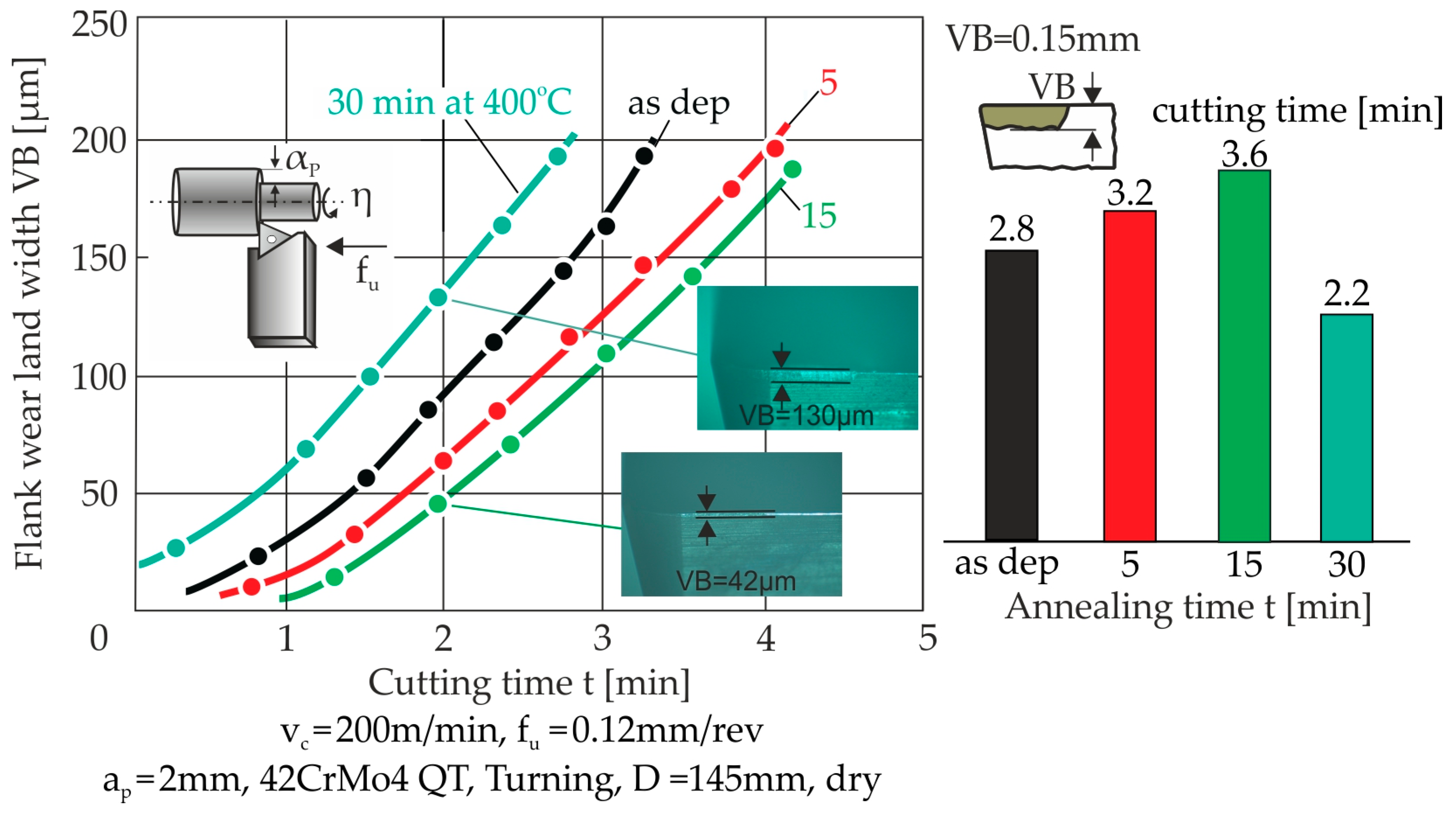
3.3.2. Cutting Investigations in Turning Hardened Steel 42CrMo4 QT and Cast Iron GG30

The turning investigations were carried out with continuous or discontinuous chip structures applying hardened steel 42CrMo4 QT and cast iron GG30, respectively, and the same cutting speed and feed as in the milling investigations presented. The results achieved in turning hardened steel are illustrated in Figure 8. In this case, due to the crystalline structure of the workpiece and the continuous turning kinematics, chip formation was continuous and led to practically unchanged cutting loads on the coated cutting edge. Similarly to milling, an improvement in the life of the coated tool was observed at annealing times of up to 15 min; beyond this time, a decrease in the tool life occurred. Longer tool life was achieved in turning compared with the corresponding annealed inserts in milling. This was attributed to the lower stress, strain and strain rates in the coating developed during turning, as explained in [21]. Thus, coating wear developed in turning mainly due to abrasion phenomena, while in milling, it was due to the fatigue strength of the coating.
In order to evaluate the impact of dynamic cutting loads on the coated cutting edge during turning, further experiments were carried out using GG30 cast iron. The crystalline structure of this material leads to discontinuous chip formation and therefore to floating cutting loads. The coated tool exhibited extended tool life at annealing times up to 15 min, as shown in Figure 9. In the as-deposited coating case, the cutting time achieved for a flank wear width of 0.15 mm was approximately 21 min. The maximum tool life, recorded at an annealing time of 15 min, reached 27 min. In contrast, the shortest tool life was observed after an annealing time of 30 min. These results are in accordance with the relevant milling studies introduced previously.

3.3.3. Theoretical Explanation of the Results Obtained Based on FEM Calculations

The comparatively increased wear resistance of the coated tools for 15 min of annealing is theoretically explained by FEM calculations according to the methodologies described in [3]. In the FEA model used in the milling case, the chip contact length at the maximum cutting force was considered. The cutting force components were measured in the longitudinal, radial, and tangential directions. These components were transformed into a tool rake reference system, parallel (Fκt) and perpendicular (Fκn) to the cutting edge and parallel to the cutting speed (Fv). The experimentally determined values are shown in Figure 10. The mechanical properties of the film presented in Figure 4 were considered. These were applied to the entire coating thickness, as explained in Section 3.1. The equivalent stress distributions calculated in the tip region of the untreated as well as the annealed coated tools for 15 min are shown in Figure 10. In the case of untreated coated tools, the equivalent maximum stress in the roundness of the tip near the flank is greater than the yield stress of the coating. Consequently, a region of film overstress develops, resulting in an early fracture of the coating and, consequently, limiting the tool life in turning and milling. This limitation is more pronounced in milling, since comparatively higher strain rates occur in the transition region from flank to rake [21]. Furthermore, in the case of an annealing time of 15 min compared to untreated tools, due to the improved mechanical properties of the coating, the stresses developed during turning and milling were lower than the film yield stress. The onset of coating fracture in this case occurred later and the wear behavior was improved.

4. Conclusions

Annealing of coated tools has been shown to be an effective post-treatment method to improve their cutting performance. The applied annealing duration should be carefully aligned with the changes in the mechanical and fatigue properties of the coating. The wear resistance of coated tools subjected to various annealing durations was investigated in cutting operations with either quasi-constant or repetitive loads. The results presented indicate that annealing at an optimized duration significantly extended the life of CrAlN-coated tools in milling and turning. Given its simplicity, annealing is highly recommended as effective in the post-processing of coated cutting tools.

Author Contributions

Conceptualization, G.S.; methodology, G.S. and K.-D.B.; software, G.S. and A.B.; validation, G.S., D.T. and A.B.; formal analysis, G.S.; investigation, G.S., D.T., K.-D.B., F.S. and A.B.; data curation, G.S.; writing—original draft preparation, G.S., F.S. and K.-D.B.; writing—review and editing, G.S. and K.-D.B.; visualization, G.S.; supervision, G.S. All authors have read and agreed to the published version of the manuscript.

Funding

This research received no external funding.

Institutional Review Board Statement

Not applicable.

Informed Consent Statement

Not applicable.

Data Availability Statement

Data are contained within the article.

Conflicts of Interest

Author Antonios Bouzakis was employed by the company Impact-BZ. The remaining authors declare that the research was conducted in the absence of any commercial or financial relationships that could be construed as a potential conflict of interest.

References

  1. Deng, Y.; Chen, W.; Li, B.; Wang, C.; Kuang, T.; Li, Y. Physical vapor deposition technology for coated cutting tools: A review. Ceram. Int. 2020, 46, 18373–18390. [Google Scholar] [CrossRef]
  2. Al-Zubaidi, S.; Ghani, J.A.; Che Haron, C.H.; Mohammed, M.N.; Jameel Al-Tamimi, A.N.; M.Sarhan, S.; Salleh, M.S.; Abdulrazaq, M.; Abdullah, O.I. Development of Hybrid Intelligent Models for Prediction Machining Performance Measure in End Milling of Ti6Al4V Alloy with PVD Coated Tool under Dry Cutting Conditions. Lubricants 2022, 10, 236. [Google Scholar] [CrossRef]
  3. Bouzakis, K.-D.; Michailidis, N.; Skordaris, G.; Bouzakis, E.; Biermann, D.; M’Saoubi, R. Cutting with coated tools: Coating technologies, characterization methods and performance optimization. CIRP Ann. Manuf. Technol. 2012, 61, 703–723. [Google Scholar] [CrossRef]
  4. Bobzin, K. High-performance coatings for cutting tools. CIRP J. Manuf. Sci. Technol. 2017, 18, 1–9. [Google Scholar] [CrossRef]
  5. Yaqoob, S.; Ghani, J.A.; Jouini, N.; Juri, A.Z. Performance Evaluation of PVD and CVD Multilayer-Coated Tools in Machining High-Strength Steel. Coatings 2024, 14, 865. [Google Scholar] [CrossRef]
  6. Liu, W.; Chu, Q.; Zeng, J.; He, R.; Wu, H.; Wu, Z.; Wu, S. PVD-CrAlN and TiAlN coated Si3N4 ceramic cutting inserts-2. High speed face milling performance and wear mechanism study. Ceram. Int. 2017, 43, 9488–9492. [Google Scholar] [CrossRef]
  7. Paiva, J.M.; Fox-Rabinovich, G.; Junior, E.L.; Stolf, P.; Ahmed, Y.S.; Martins, M.M.; Bork, C.; Veldhuis, S. Tribological and Wear Performance of Nanocomposite PVD Hard Coatings Deposited on Aluminum Die Casting Tool. Materials 2018, 11, 358. [Google Scholar] [CrossRef] [PubMed]
  8. Zimmer, O.; Krülle, T.; Litterst, T. The Influence of Bias Voltage and Gas Pressure on Edge Covering during the Arc-PVD Deposition of Hard Coatings. Coatings 2024, 14, 732. [Google Scholar] [CrossRef]
  9. Mativenga, P.; Schoop, J.; Jawahir, I.S.; Biermann, D.; Kipp, M.; Murat Kilic, Z.; Ozel, T.; Wertheim, R.; Arrazola, P.; Boing, D. Engineered design of cutting tool material, geometry, and coating for optimal performance and customized applications: A review. CIRP-J. Manuf. Sci. Technol. 2024, 52, 212–228. [Google Scholar] [CrossRef]
  10. Gadge, M.; Lohar, G.; Chinchanikar, S. A review on micro-blasting as surface treatment technique for improved cutting tool performance. Mater. Today Proc. 2022, 64, 725–730. [Google Scholar] [CrossRef]
  11. Faksa, L.; Daves, W.; Ecker, W.; Klünsner, T.; Tkadletz, M.; Czett, C. Effect of shot peening on residual stresses and crack closure in CVD coated hard metal cutting inserts. Int. J. Refract. Met. Hard Mater. 2019, 82, 174–182. [Google Scholar] [CrossRef]
  12. Bagherifard, S.; Parienete, I.F.; Ghelichi, R.; Guagliano, M.; Vezzù, S. Effect of Shot Peening on Residual Stresses and Surface Work-Hardening in Cold Sprayed Coatings. Key Eng. Mater. 2009, 417–418, 397–400. [Google Scholar] [CrossRef]
  13. Liu, G.; Shen, Z.; Huang, G.; He, L.; Mu, R.; Zhao, W. Effects of shot peening on microstructure, thermal performance, and failure mechanism of thermal barrier coatings. J. Am. Ceram. Soc. 2022, 105, 4521–4531. [Google Scholar] [CrossRef]
  14. Fox-Rabinovich, G.S.; Endrino, J.L.; Beake, B.D.; Aguirre, M.H.; Veldhuis, S.C.; Quinto, D.T.; Bauer, C.E.; Kovalev, A.I.; Gray, A. Effect of temperature of annealing below 900 °C on structure, properties and tool life of an AlTiN coating under various cutting conditions. Surf. Coat. Technol. 2008, 202, 2985–2992. [Google Scholar] [CrossRef]
  15. Priyadarshini, B.; Anwar, S.; Choudhary, B.; Anwar, S. Influence of annealing temperature on microstructural, mechanical and chemical properties of CrAlN coatings. Phys. B Condens. Matter 2023, 669, 415304. [Google Scholar] [CrossRef]
  16. Wang, L.; Nie, X. Effect of Annealing Temperature on Tribological Properties and Material Transfer Phenomena of CrN and CrAlN Coatings. J. Mater. Eng. Perform. 2014, 23, 560–571. [Google Scholar] [CrossRef]
  17. Bouzakis, K.-D.; Skordaris, G.; Hadjiyiannis, S.; Mirisidis, I.; Michailidis, N.; Erkens, G.; Wirth, I. The effect of annealing duration at deposition temperature on the strength properties gradation of PVD films and on the wear behaviour of coated cemented carbide inserts. Surf. Coat. Technol. 2006, 200, 500–4510. [Google Scholar] [CrossRef]
  18. Cremer, R.; Witthaut, M.; Neuschuetz, D. Experimental determination of the metastable (Ti,Al)N phase diagram up to 700 °C. In Proceedings of the TMS Annual Meeting, San Antonio, TX, USA, 15–19 February 1998; pp. 249–258. [Google Scholar]
  19. Chou, W.-J.; Yu, G.-P.; Huang, J.-H. Effect of heat treatment on the structure and properties of ion-plated TiN films. Surf. Coat. Technol. 2003, 168, 43–50. [Google Scholar] [CrossRef]
  20. Bunshah, R.F. Handbook of Hard Coatings, Noyes Publications; William Andrew Publishing, LLC: Norwich, NY, USA, 2001. [Google Scholar]
  21. Bouzakis, A.; Skordaris, G.; Bouzakis, E.; Bouzakis, K.-D.; Tsakalidis, D. Wear evolution on PVD coated cutting tool flank and rake explained considering stress, strain and strain-rate dependent material properties. Coatings 2023, 13, 1082. [Google Scholar] [CrossRef]
  22. Impact-BZ Ltd. Available online: www.impact-bz.com (accessed on 28 February 2025).
Figure 1. (a) Geometry of the applied coating. (b) Main data of the used workpiece materials.
Coatings 15 00311 g001
Figure 2. Vacuum device used for thermal processing: horizontal tube furnace, quartz tube for placement the coated samples, vacuum pump, inert gas supply, pressure and temperature gauge.
Coatings 15 00311 g002
Figure 3. Impact tester and the related fixtures for conducting perpendicular and inclined impact tests. Displays the pressure inside the quartz tube, providing real-time monitoring during the process.
Coatings 15 00311 g003
Figure 4. (a) Indentation depth versus increasing force during the nanoindentation on the various heat-treated coatings. (b) The determined stress–strain curves of the annealed coatings.
Coatings 15 00311 g004
Figure 5. (a) Coating failure depth versus the impact load after 106 impacts during the perpendicular impact test on the variously annealed coated inserts. (b) Determined critical impact force after 106 impacts.
Coatings 15 00311 g005
Figure 6. Remaining imprint depth versus the number of impacts after inclined impact tests on the investigated annealed coated inserts.
Coatings 15 00311 g006
Figure 7. Flank wear development versus the number of cuts in milling hardened steel 42CrMo4 QT using the untreated and annealed coated tools.
Coatings 15 00311 g007
Figure 8. Flank wear development versus the number of cuts in turning hardened steel 42CrMo4 QT using the untreated and annealed coated tools.
Coatings 15 00311 g008
Figure 9. Flank wear development versus the number of cuts in turning cast iron GG30 using untreated and various long-annealed coated tools.
Coatings 15 00311 g009
Figure 10. von Mises stress fields within the as-deposited and annealed for 15 min coated cutting edge in milling hardened steel 42CrMo4 QT considering the actual coating and substrate mechanical properties.
Coatings 15 00311 g010
Disclaimer/Publisher’s Note: The statements, opinions and data contained in all publications are solely those of the individual author(s) and contributor(s) and not of MDPI and/or the editor(s). MDPI and/or the editor(s) disclaim responsibility for any injury to people or property resulting from any ideas, methods, instructions or products referred to in the content.

