Article

Impact of Irradiation on Corrosion Performance of Hybrid Organic/Inorganic Coatings on Austenitic Stainless Steel

1
Mechanical and Aerospace Engineering, The University of Alabama in Huntsville, Huntsville, AL 35899, USA
2
Sandia National Laboratories, Albuquerque, NM 87123, USA
3
Luna Labs, Charlottesville, VA 22930, USA
*
Author to whom correspondence should be addressed.
Coatings 2025, 15(3), 312; https://doi.org/10.3390/coatings15030312
Submission received: 23 January 2025 / Revised: 21 February 2025 / Accepted: 26 February 2025 / Published: 7 March 2025
(This article belongs to the Section Corrosion, Wear and Erosion)

Abstract

:
The effects of gamma radiation on the performance of two corrosion-resistant coatings applied to stainless-steel 304L (SS304L) surfaces are presented. Specifically, the ability of the coatings to mitigate corrosion of SS304L surfaces as a function of the dose received (0–1300 Mrad) and dose rate (176 compared to 1054 rad/s) is evaluated using electrochemical methods, spectroscopy, and microscopy. Coating A, an organic/inorganic hybrid coating consisting of a two-part silica ceramic component and a polymer linker was evaluated in comparison to Coating B, which utilized Coating A as a topcoat for a commercial, off-the-shelf, Zn-rich primer. Post irradiation, Coating A demonstrated some corrosion protection following exposure to low levels of gamma radiation, but coating degradation occurred with an increased exposure dose and resulted in isolated regions of corrosion initiation. For Coating B, greater corrosion resistance was observed compared to Coating A due to the sacrificial nature of the Zn at elevated doses of gamma radiation. No effect of the dose rate (for the single dose examined) was observed for either coating. It is proposed for Coating B that as the polymer coating thermally degrades above 250 °C (bond scission of the polymer occurs), the remaining Zinc layer adhered to the SS304L post-irradiation enables enhanced corrosion resistance as compared to Coating A, which displays solely polymer degradation. The results presented herein establish an understanding of coating behavior with radiation exposure, specifically the relationship between corrosion coating performance and radiation dose, and can inform ageing and lifetime management for various applications.

1. Introduction

Stainless-steel (SS) materials are often employed in many engineering applications due to their high corrosion resistance. However, when SS is exposed to marine and/or near-marine environments, containing chloride-rich sea-salt solutions, it is susceptible to localized corrosion and pitting [1,2]. Under these corrosive conditions, corrosion-resistant coatings can be applied to extend the overall service lifetime of a given part. While corrosion-resistant coatings can offer protection for in-service metal components, in some cases, the environment that the material and coating are exposed to involves ionizing radiation, such as applications for aerospace, the nuclear fuel cycle, and nuclear medicine [3,4]. Understanding the susceptibility or resiliency of coatings, particularly the organic portions, to ionizing radiation and their subsequent corrosion resistance is key to predicting and extending part lifetimes under such conditions.
One example application in which SS can be exposed to a near-marine environment under ionizing radiation is spent nuclear fuel (SNF) dry storage. In the United States, dry storage canisters are made from welded austenitic stainless steel [5], which under increased storage times, can be susceptible to corrosion and stress corrosion cracking. Corrosion-resistant coatings are a potential strategy for mitigation; however, as SNF canisters contain radioactive waste, any coating applied to the canister surface will be exposed to radiation during its lifetime. The estimated total dose a coating can receive is dependent on application timing, as with radioactive decay; the dose rate is highest at time = 0 (initial loading) and decreases exponentially as a function of time [6]. Therefore, a coating applied prior to SNF loading and used for 300 years of storage would have a total dose of roughly 725 Mrad (this is, assuming 45–48 gigawatt-days per metric ton of uranium (4% 235U) burn up) [6]. However, if applied as a mitigation strategy after five to twenty years of storage, the coating would have a variance in the total dose received dependent on the application time post-loading, with ~495 Mrad from 5 to 300 years and ~314 Mrad for 20–300 years [6]. Finally, if applied as a repair strategy after 40 years of storage, the coating would experience ~200 Mrad from 40 to 300 years [6]. Knowledge of the relationship between the coating performance and dose received is critical to understanding how a particular coating can prevent, repair, or mitigate possible stress corrosion cracking for SNF dry storage canisters or other ionizing radiation scenarios.
Different approaches have been explored to prevent potential corrosion of SNF canisters including cold spray of metallic coatings [7,8,9,10], peening methods, and coating materials that contain organic components. Coating strategies which have been explored include silica-based ceramic coatings [11]. Wang et al. showed that perhydropolysilazane-derived ceramic coatings improved the corrosion resistance of SS304L substrates and found that the coatings crosslinking at 600 °C offered better corrosion resistance compared to room-temperature-crosslinked coatings [11]. Hybridization of ceramic coatings with organic components is also commonly employed to decrease the coating brittleness and increase hydrophobicity. When combined with an epoxy, silica/epoxy resin hybrid coatings demonstrated high hardness and abrasion resistance and passed wet adhesion testing when cured at 80 °C [12]. With a large diversity in sol–gel compositions, there is flexibility to improve the strength of the coating by adjusting the metal composition or incorporating organic additives [13]. A commonly used additive to increase the mechanical robustness is tetraethoxysilane, which has been routinely applied to low-bulk-density SiO2 sol–gel coatings, increasing the overall strength of a coating [14]. Another common strategy to improve corrosion resistance in coatings is to apply galvanic protection, i.e., utilizing Zn as a sacrificial anodic material [15]. Zn-rich coatings have been shown to decrease the risk of stress corrosion cracking in Al-Mg alloys [16,17,18] and provide cathodic protection on steel [19]. However, for the non-metallic coatings, radiation damage becomes a concern for long-term performance. One study on silica-impregnated polymers explored the structural, optical, dielectric, and thermal effects of radiation on magnesium silicate/polyurethane materials. It was determined that as the radiation dose increases, crosslinking, the dielectric constant, and activation energy all increase [20]. Meanwhile, degradation, decreased tensile strength, and surface etching were all observed in various biodegradable polyurethanes upon gamma radiation exposure [21]. While there is a large body of research on the application of radiation to alter surface physical and chemical properties of various materials [22,23,24], as well as coatings, including polymers [25], silicones [26], and epoxies [27], a full understanding of the subsequent coating lifetime with respect to corrosion resistance has not been fully explored. For applications such as SNF storage, more research on gamma radiation effects on the organic portions of polymer materials would aid in overall lifetime prediction for the resistance of a coating.
In this study, the performance levels of two coating systems, a two-part silica ceramic with a polymer linker (Coating A) and a Zn-rich primer with Coating A applied as a topcoat (Coating B), were evaluated as a function of the radiation dose received. Coating A is a proprietary hybrid coating consisting of a hard-ceramic hybrid matrix based on a silane-modified polymer. This hybridization results in a coating with high durability and toughness for abrasion resistance and corrosion protection. The addition of the polymer additives increased the hydrophobicity and allowed for the tunability of properties, specifically hardness, flexibility, and modulus of elasticity, to meet the specific needs of an application [28]. Coating B consists of a commercial, off-the-shelf (COTS), Zn-rich primer with Coating A as a topcoat to slow the oxidation of the Zn in the primer. Post radiation exposure, electrochemical polarization and subsequent microscopy and spectroscopy were applied to develop a mechanistic understanding of potential coating degradation and influences on corrosion resistance. Laser-induced breakdown spectroscopy (LIBS) provided data on the presence of various corrosion products that formed during the cyclic potentiodynamic polarization (CPP) experiments. Changes in the open circuit potential (OCP) as a function of the dose were compared to determine the corrosion susceptibility levels and surface states of the materials. The effect of the dose rate was also explored by comparing a shutter array (SA) at a dose rate of 1054 rad/s to a linear array (LA) at a dose rate of 176 rad/s for samples exposed to 350 Mrad for each coating. Additionally, unexposed baseline and irradiated coatings were evaluated by differential scanning calorimetry (DSC) and thermogravimetric analysis (TGA) to provide data on the thermal properties of the coatings, decoupling radiation and thermal effects. The developed results as a function of the radiation dose are compared and implications for coatings’ lifetimes under corrosive and ionizing radiation relevant to SNF canister conditions are discussed. Furthermore, a discussion of the proposed breakdown of the organic portion of the polymer and how this impacts coating degradation is presented.

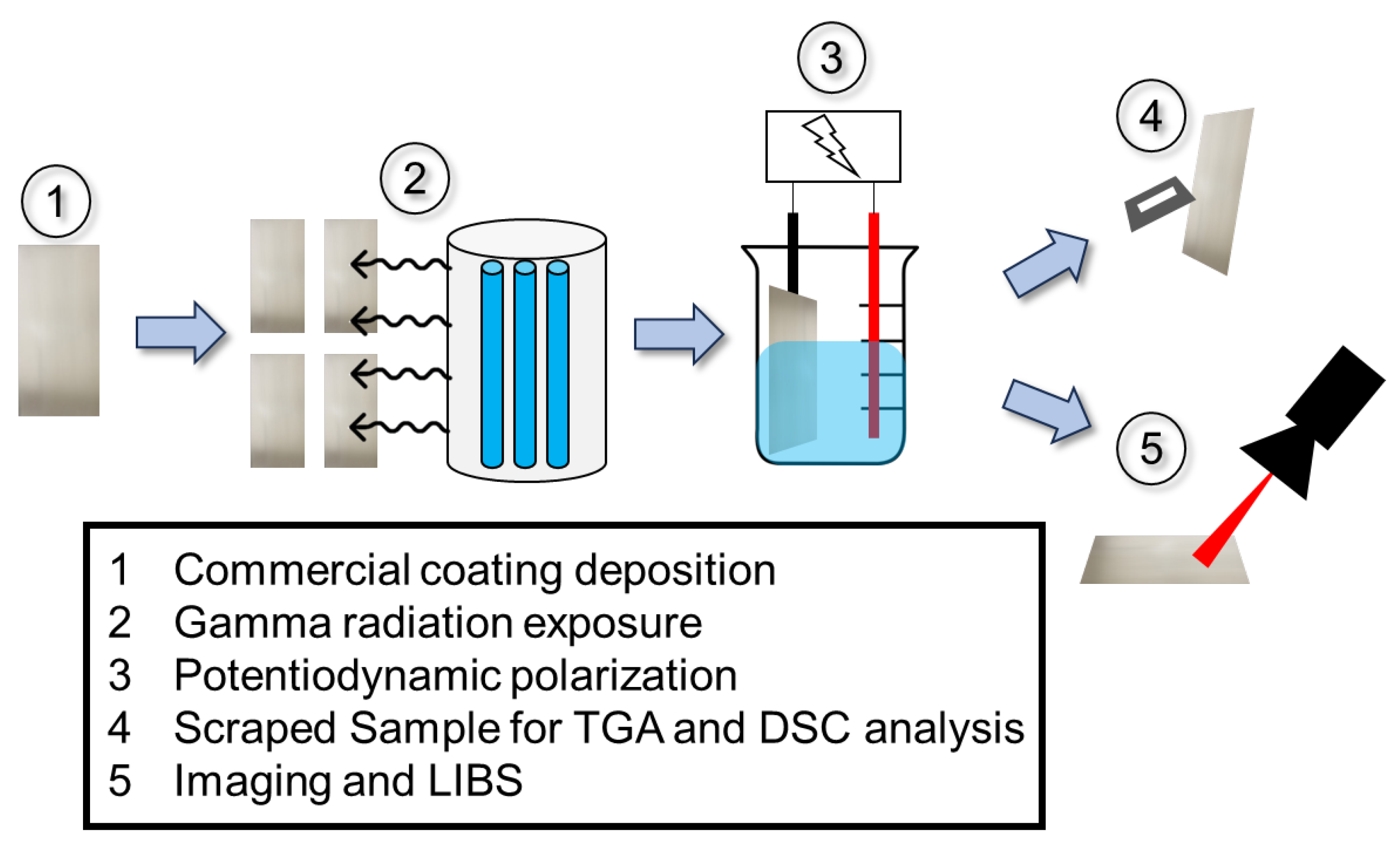
2. Materials and Methods

2.1. Materials

Two commercial polymer coatings applied on SS304L coupons were examined. Coating A is a two-part silica, hard-ceramic hybrid matrix based on a silane-modified polyurethane. Coating B is composed of the same two-part silica ceramic with the polymer linker applied on top of a commercial, off-the-shelf, Zn-rich primer layer [6]. The coatings were commercially developed and applied by Luna Labs on 7.62 × 15.24 × 0.165 cm coupons of SS304L [6]. The surface was ground with 180-grit sandpaper prior to coating application. Coatings were applied to an average thickness of 2.0 ± 0.1 mm for Coating A and 160 ± 2 mm for Coating B. Coated coupons were tested post-exposure to a range of irradiated conditions, and one of each coating was examined in the non-irradiated, as-coated condition for comparison. An example experimental flow is shown in Figure 1 for full analysis; baseline unirradiated samples were also examined and are noted throughout the text for comparison.

2.2. Thermal Gravimetric Analysis/Differential Scanning Calorimetry

As-received samples of Coating A and B were analyzed by TGA/DSC by heating scrapings of the coatings from 25 to 850 °C at a ramp rate of 1 °C/min in compressed air flowing at 100 mL/min using SDT Q600 V20.9 Build 20. The DSC heat flow was calibrated prior to testing.

2.3. Radiation Exposures

One coupon of each coating was set aside in the as-coated condition as a ‘non-irradiated’ sample. The other twelve coupons (six of each coating type) were irradiated using the Gamma Irradiation Facility (GIF) at Sandia National Laboratories to achieve total doses of 100, 200, 350, 730, and 1300 Mrad [6,29]. Samples were placed in two different exposure cells: a lower-dose-rate linear 60Co array (LA—176 rad/s) and a higher-dose-rate circular 60Co shutter array (SA—1054 rad/s). See Table 1 for the specific testing environments based on possible predicted total doses (dependent on initial heat loads and exposure times) expected on SNF canister surfaces [6]. The two different types of exposure cells were used to cover a larger range of overall radiation doses. Additionally, the 350 Mrad exposure was performed using both the SA and LA exposure rates to enable the comparison of dose rate effects on the samples. Samples exposed in the LA were mounted on custom-built wooden fixtures to hold them at the correct height for uniform exposure in front of the linear source. Minimal metal was used in the construction of the fixtures to reduce attenuation and localized heating during exposure. The fixture was placed adjacent to the containment pool curb to achieve the highest dose rate possible in the LA. A short length of SS wire was stretched across the front of the samples to hold them in place during the exposure and to prevent them from falling into the containment pool. Previous measurements performed by the GIF have demonstrated that samples exposed to the LA maintain a temperature around ambient (~25 °C) [6]. Samples exposed to the SA were grouped into three sample stacks with 6 coupons per stack. Each stack contained at least one sample of each coating (other coating types not reported herein were simultaneously exposed with coatings A and B), and the stacks were removed at different time intervals to achieve different total doses. The sample stacks were overwrapped with two layers of aluminum foil, and a fiberglass-insulated, exposed junction, T-type thermocouple was placed in the middle of the stack (between the fourth and fifth coupons) to monitor the temperatures of the stacks during exposure. Images of the sample exposure setups were previously detailed in Nation et al. [6]. The stacks placed in the SA self-heated during exposure due to the large mass of the stack and the high flux. The stack temperature stabilized between 72 and 82 °C during exposure in the SA; the average is reported here (~77 °C).
The experimental setup performed at the GIF is similar to that described in the ASTM D4082 method—gamma radiation for use in nuclear power plants [30]—but does not fully meet the specification provided by the standard. Deviations from the standard were performed to assist in understanding the effects of radiation and/or the dose rate with respect to relevant doses predicted for SNF canister storage applications. In the ASTM D4082 standard, coupons are to be exposed to 1000 Mrad at a dose rate of ~275 rad/s (or greater) using a 60Co source with 10% uniformity from sample to sample and maintain a temperature < 60 °C. Specific differences between the ASTM D4082 standard and the GIF exposures are as follows: (1) samples irradiated with the LA are subjected to dose rates lower than the standard; (2) samples irradiated in the SA are subjected to dose rates high enough (1054 rad/s max) to meet the standard, though only the 1300 Mrad samples meet the dose threshold specified in the standard (1000 Mrad); (3) samples in the SA achieve temperatures > 60 °C (exceeding the standard); and (4) the examination methods recommended in the ASTM D4082 standard are primarily visual inspection methods—specifically, evidence of chalking (ASTM-D659 [31]), cracking (ASTM-D661 [32]), blistering (ASTM-D714 [33]), flaking (ASTM-D 772 [34]), or delamination [30]—which were not specifically performed in this study. Variances from the ASTM D4082 standard in dose rate, overall dose, and the exceptions made regarding heating of the sample enabled the modification of the irradiation testing to develop more relevant exposure conditions for potential SNF canister coatings.

2.4. Electrochemical Testing

After radiation exposure, electrochemical evaluation was carried out using a BioLogic VMP-300 potentiostat. Standard silver/silver chloride (Ag/AgCl) reference electrodes from Fisherbrand accumet, were used for all experiments, and all potentials are reported versus Ag/AgCl. The coupons were exposed for 30 min at OCP, followed by a CPP scan. The CPP forward scan initiated 100 mV below the OCP and scanned up to 1.2 VAg/AgCl at a scan rate of 0.167 mV/s, followed by a reverse scan down to 200 mV below the OCP. The electrolyte used was quiescent, 0.6 M sodium chloride (NaCl) solution (Sigma Aldrich, St. Louis, MO, USA, ≥99.0% pure), and all tests were conducted at room temperature. For each coupon, three areas were evaluated; one representative scan is shown per condition, and full datasets are provided in the Supplementary Material. Current density was normalized to the flat cell test area of 1 cm2; however, the optically observed corroded regions post electrochemical characterization were measured from Keyence images using ImageJ (v1.53) analysis and were ~1.44 cm2 ± 0.08 for Coating A and ~1.19 cm2 ± 0.04 for Coating B. The corrosion outside of the test area likely indicates uptake of the brine solution by the coating; however, while it is noted when the occurrence of spreading was observed, for the purpose of this paper, electrochemical data are presented vs. the 1 cm2 test area. Where possible, the breakdown potential (Eb) was approximated by averaging the three runs for each condition. The OCP values on the forward and reverse CPP scans were calculated using the built-in function in BioLogic software. Within this work, the reverse OCP is defined as the location where the current density is at a minimum on the reverse scan, to allow for comparisons between the forward and reverse scans and across the various exposed coupons.

2.5. Post-Exposure Optical Imaging and Laser-Induced Breakdown Spectroscopy

Pre- and post-irradiation and electrochemical testing, optical images were collected using a Keyence VHX-7000 (Keyence Corporation of America, Itasca, IL, USA)with a 20× objective lens. Additionally, laser-induced breakdown spectroscopy (LIBS) analysis was performed to qualitatively compare corrosion damage post irradiation and CPP using a Keyence EA-300 Laser Element Analyzer (Keyence Corporation of America, Itasca, IL, USA) in select regions. Elements of interest identified through LIBS analysis were silicon (Si), chromium (Cr), nickel (Ni), iron (Fe), and zinc (Zn). For simplicity in the images, no distinction of metal speciation is made; the areas are either labeled Si, Cr, Zn, Fe, or SS (where Fe, Cr, and/or Ni are present simultaneously). Due to the limited sensitivity of LIBS, no distinction is made regarding the exact chemical species (e.g., oxide versus hydroxide species); however, the elemental composition paired with visual inspection from Keyence images and electrochemical behavior can guide probable compositional identification. Additionally, the presence (or absence) of elements detected via LIBS is used to guide the probable degradation discussion for each of the coatings, though it is important to note that any conclusions are generalized as LIBS was not performed across the entire test area but rather on isolated features of interest. Full datasets for LIBS with measured elemental percentages are provided in the Supplementary Material.

3. Results

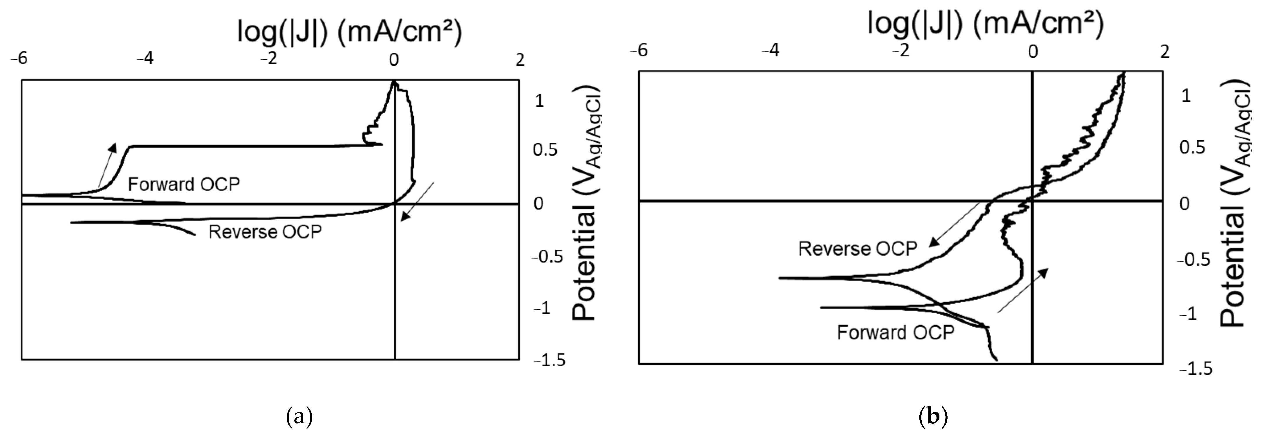
3.1. Baseline Performance

As-received samples of Coatings A and B were analyzed by TGA/DSC. Figure 2 shows the resulting weight variation (solid lines) and heat flow (dashed lines) plotted against temperature for Coating A (blue) and Coating B (red). Coating A displays a characteristic S-curve for the weight loss, with the onset of thermal degradation at about 250 °C, the inflection point around 300 °C, and increased weight loss beyond 300 °C. However, Coating B displays a very different behavior, with mass loss occurring at about 275 °C (likely associated with the small exothermic peak), continued mass loss until ~420 °C at which an endothermic event occurs, and sample mass increases.
The as-received coatings were also analyzed with electrochemical characterization and subsequent imaging. Baseline electrochemical scans of Coating A generally displayed passive behavior (Supplementary Material), with no breakdown observed at potentials < 1.1 VAg/AgCl. However, in one case, shown in Figure 3a, active corrosion and breakdown were observed around + 0.5 VAg/AgCl. Further interrogation of the test location was performed using LIBS, as shown in Figure 4a. For Coating A (Figure 4a), SS was likely identifiable due to the thin layer of coating; only SS and no Si was detected in the crevice interior, suggesting the coating had degraded in this location (red). This was compared to the region far away from the crevice (blue), where both SS and Si were detected, indicating the coating was still intact in that location after electrochemical exposure.
Baseline electrochemical polarization scans were performed on the non-irradiated Coating B, and an exemplar scan is shown in Figure 3b. On the forward CPP scan, the OCP has a value close to the OCP of Zn in 0.6 M NaCl (roughly −1 VAg/AgCl) [35]. On the anodic branch of the initial CPP, the current density gradually decreases above −0.7 VAg/AgCl, likely associated with the formation of ZnO or Zn(OH)2 [36] from the underlying Zn-rich primer, thus passivating the surface. As the potential is scanned more positively, the current density slightly increases, potentially indicating breakdown of this passive film. On the reverse scan, a re-passivation is observed around 0.1 VAg/AgCl, and as the reverse scan continues, the OCP shifts to a more positive potential, suggesting a mixed potential between Zn and SS. Figure 4b shows the LIBS results of the non-irradiated Coating B sample after polarization. The bulk of the surface consists of Si and Zn from the topcoat and Zn-rich primer, respectively. Surface cracks are visually present in both regions tested. All the regions tested show areas where Cr exists without Fe, suggesting migration of Cr from SS and/or dissolution of Fe. Zn is often co-located with O and H, suggesting Zn oxidation products formed.

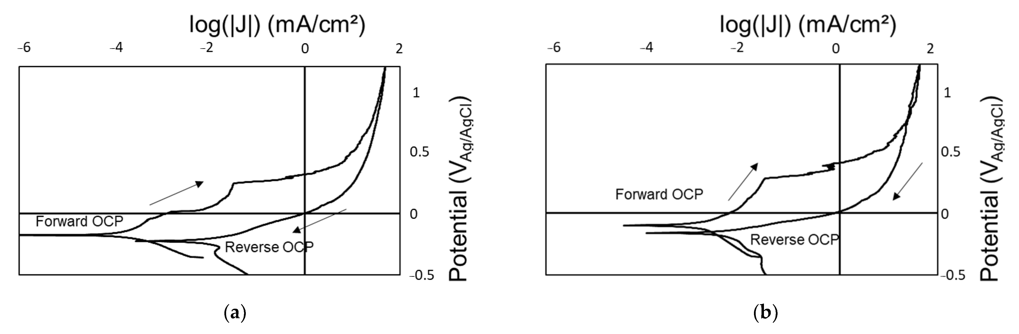
3.2. Impact of Radiation on Coating Performance

TGA and DSC were performed for Coating A post 350 Mrad irradiation + electrochemical analysis and Coating B post 1300 Mrad irradiation + electrochemical analysis. We selected 350 Mrad irradiation for Coating A as it was the highest radiation dose for which significant sample mass could be collected; the coating was visually damaged and sufficient samples for analysis could not be collected from the 730 and 1300 Mrad coupons. The results are shown below in Figure 5.
Figure 6 shows electrochemical polarization scans for Coating A after exposure to 350 Mrad (Figure 6a) and 1300 Mrad (Figure 6b). Figure 7 presents the resulting OCP and Eb (breakdown potential associated with the onset of active corrosion). The standard deviations for the OCP values of Coating A at 0 and 100 Mrad (Figure 7) are large as some samples did not display active corrosion during CPP testing. However, at 200 Mrad and above, all runs show signs of corrosion, and the forward scan OCP is more positive than the reverse scan OCP. The Eb shown in Figure 7b also displays a decrease above 200 Mrad, again indicating increased breakdown of the coating at higher radiation exposure. With increased exposure to radiation, the observed corrosion morphology changes from filiform [37] to localized pitting [38] (see Supplementary Material).
Following CPP scans, LIBS analysis was performed on the samples of Coating A exposed to 350 Mrad LA and 1300 Mrad SA to evaluate the compositions of the various features observed optically. Figure 8a shows the LIBS results from two spots analyzed on Coating A, after exposure to 350 Mrad, 25 °C. Si was not identified through LIBS and only products of SS corrosion or SS could be identified on the surface. The red spot evaluates a red/brown corrosion product, identified with the components of SS and likely Fe2O3 and/or Fe(OH)3. The blue spot evaluates a pit in the center of the test area, again displaying SS identification. Figure 8b shows the LIBS analysis after exposure to 1300 Mrad SA radiation, 77 °C, and CPP testing. Again, a significant amount of rust can be observed, indicated by the red color (Figure 8b red). The blue spot in Figure 8b evaluates a pit, identifying only SS, which indicates the coating likely failed in this spot. Some silicon was identified across the test region (see Supplementary Material), suggesting some of the coating survived the heaviest radiation dose. In general, as the radiation dose increases, the samples visibly appear more susceptible to crevicing at the edge of the test areas (where the coatings are in contact with the electrochemical cell o-ring).
Figure 9 shows the resulting CPP analysis of Coating B as a function of the radiation dose for 350 and 1300 Mrad, with Figure 10 summarizing the OCP and Eb values for all radiation doses tested. The electrochemical response of Coating B is much more consistent than that of Coating A. In contrast, the OCP from the reverse scan shifts to a more positive potential. In this study, Eb was observed to be between roughly 0.266 and 0.422 VAg/AgCl for all samples (Figure 10), except for the sample exposed to 1300 Mrad. This Eb was measured near a lower potential of 0.061 VAg/AgCl. The Eb for the sample exposed to 350 Mrad 75 °C SA was 0.156 V more positive than the Eb for the 350 Mrad LA sample at 25 °C, though the reverse OCP values were similar. Visible corrosion was seen in all exposed samples following the polarization measurement, and regions of metastable pitting were observed in the 350 Mrad LA sample at 25 °C, which corresponds with the visual observations presented in Figure 11.
Further inspection of the test areas of Coating B post exposure to 350 Mrad, 25 °C LA and 1300, Mrad 77 °C SA and post CPP scans were performed by LIBS and are shown in Figure 11. For the sample exposed to 350 Mrad LA, 25 °C, the red test area in Figure 11a shows the location of likely pitting where SS was detected by LIBS. The center of the blue area in Figure 11a shows a yellowish residue primarily consisting of Si and Cr and lacking Zn, whereas the edges, without or with less visible corrosion product, still display the presence of Zn. For the sample exposed to 1300 Mrad SA, 75 °C, there is significant cracking of the film outside the test area, likely from the radiation exposure (see Supplementary Material). Light-colored Cr/Zn/Si compound(s) were detected at the edge of the test area, as can be seen in the blue-outlined image in Figure 11. The red region near the edge shows a mixture of oxide and hydroxide species containing Zn, Cr, and/or Si, though the exact chemical speciation is unknown. The rust color near the red region is indicative of an iron oxide. Another observation from the CPP scans was the formation of a white ring outside the edge of the test area. This ring consists of a Zn compound, likely ZnO or Zn(OH)2, with traces of the Si organic coating and SS. This ring is most prevalent in the samples exposed to 200 and 350 Mrad LA, 25 °C, though observable in other samples as well. LIBS was performed on the white ring formed on the samples exposed to 350 Mrad LA at 25 °C and 1300 Mrad SA at 75 °C, and the results are shown in Figure 12. Predominately, Zn precipitate and Si from the coating were detected.

4. Discussion

4.1. Temperature Minimally Influences Polymer Degradation of Non-Irradiated Coatings

For the baseline coatings, the TGA curve (solid line) for Coating A—hybrid ceramic coating alone—displayed a characteristic S-curve, with mass loss beginning around 250 °C and an inflection point around 300 °C. This observed onset of thermal degradation is ~50 °C lower than values reported in the literature for polyurethane-modified silica materials [39,40]. The exothermic spike around 300–320 °C in the DSC curve might correspond to oxidation of the coating [41]. The drastic mass loss above 300 °C is due to thermal degradation [42], and when T ≥ 600 °C, only ~50% of the mass of Coating A remains. At this point, it is assumed that nearly all the polymer has degraded and only silica remains because silica has a very high melting temperature. Coating B (Zn-rich primer with a Coating A topcoat) displays a different response to the temperature ramp in the TGA. There is a small exothermic peak associated with mass loss around 275 °C, where the polymer begins to degrade. At ~420 °C, a dramatic endothermic event occurs, which is likely associated with Zn melting [35]. Comparatively, after radiation exposure, Coating A appears to have no mass loss over the range tested, which could indicate a more volatile portion of the coating was removed by radiation and what is left of the coating is agnostic to temperature change. (It should be noted that the sample mass used for this test was low, at 1 mg, which can also introduce error.) For Coating B post-irradiation, an oxidation peak appears at a much lower temperature compared to the baseline coatings (Figure 2), and the Zn spike seen around 420 °C is very small. Coating B also does not appear to oxidize (gain significant mass) as it did in the baseline TGA curve. In the TGA/DSC (Figure 2 and Figure 5) analysis of the non-irradiated polymer, thermal degradation was not seen until 250 °C, and in Coating B, Zn oxidation did not occur until 420 °C. As the thermal conditions for the radiation exposure were significantly lower (25–77 °C), it is assumed that the degradation observed was due to the effects of gamma radiation rather than the thermal effects during exposure. However, further investigation to fully decouple thermal and radiation effects on the structure and breakdown of the coatings is recommended, as effects of the ramp rate, hold time, and other temperature ranges were not fully explored.

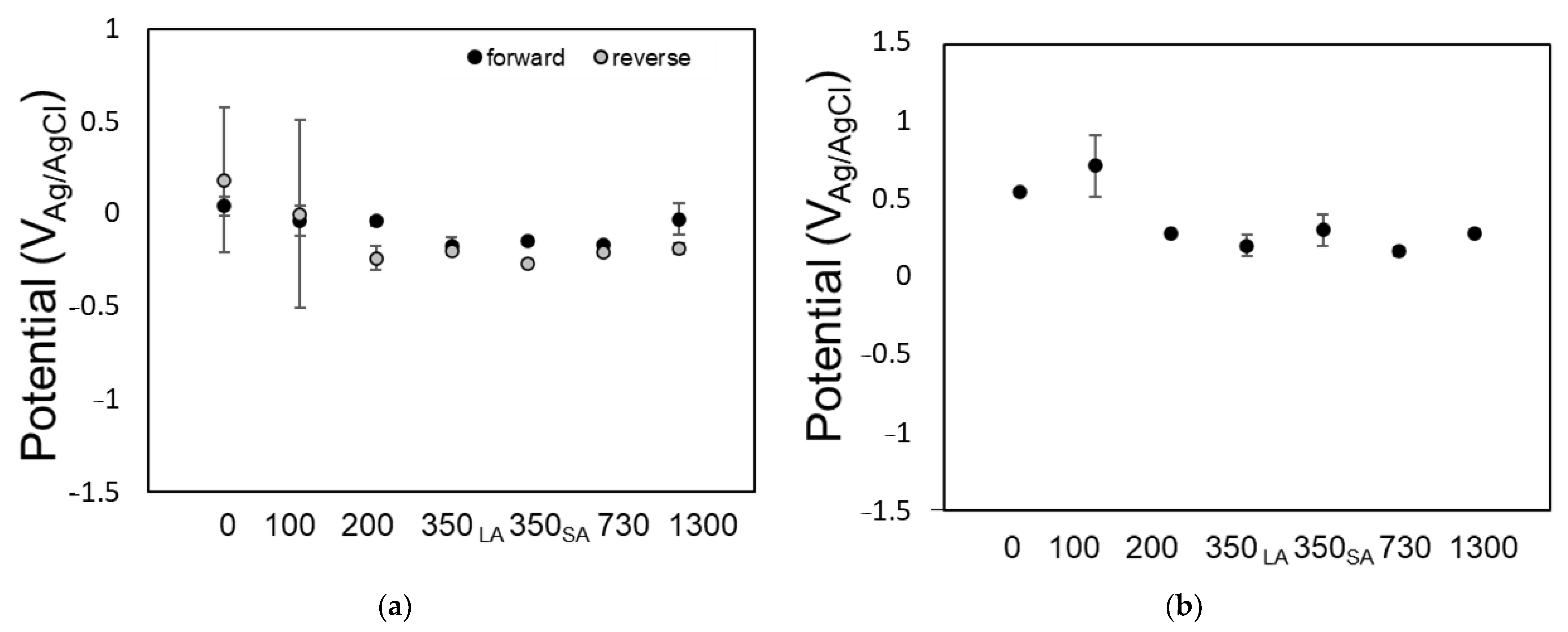
4.2. Total Radiation Dose Influences Coating Susceptibility and Electrochemical Activity

In the current exposure conditions, the total radiation dose had the largest impact on the coating performance, with coating degradation increasing with an increased dose. For Coating A, in general, as the total dose increased, corrosion was visibly more apparent after driven CPP experiments, with indications of coating breakdown through LIBS (as can be seen in the comparison of Figure 4 with Figure 8). Additionally, in TGA/DSC observations post-radiation and electrochemical polarization, the coating appears to have completely degraded, as no mass gain or oxidation peaks were observed. For Coating B, in general, as total dose received increases, the apparent susceptibility of the SS coupon to corrosion increases. However, for all radiation doses examined, Zn appears electrochemically active, suggesting a mixed OCP between Zn and SS. After exposure to gamma radiation, the two-part coating system with the Zn-rich primer (Coating B) displayed a superior corrosion resistance when compared to the organic/inorganic hybrid coating alone (Coating A). However, it is unclear whether this is due to the presence of Zn or the overall increased thickness of the coating, which can also increase resistance to degradation. With a dual-part coating, as tested in this work and others, it is believed that the ceramic portion of the coating is relatively agnostic to radiation [43,44], while susceptibility is likely due to the polymer component. Previous research has shown that although polyurethanes, for polymers, have good resistance to radiation [21], they are not immune to radiation damage. For example, when thermoplastic polyurethanes with and without chain extensions were exposed to gamma radiation, degradation was observed of the chain-extended polyurethanes and increased crosslinking in nonchain-extended polyurethanes [45]. Both crosslinking and degradation dominated in the soft segments of polyurethane. In a different study on the effect of gamma radiation on a polyester-based polyurethane, it was concluded that radiation exposure caused the average molecular weight to increase, suggesting a crosslinking reaction involving secondary alkyl radicals [46]. This study also concluded that radiation-induced scission produces various radical products. This degradation has quantifiable effects on the mechanical properties of polyurethanes. Ferreño et al. [47] identified a threshold dose of 300 kGy (30 Mrad) for the onset of mechanical degradation in polyurethane joints exposed to gamma radiation. As Coating A displayed a strong response to radiation, especially noted by the decrease in Eb in Figure 6, it is likely the polymer portion of Coatings A and B that greatly influences the coating failure response. In the case of Coating B, the Zn-rich primer (and increased thickness of the coating) provides a subsequent corrosion barrier. A schematic of this proposed mechanism is depicted below in Figure 13. It is proposed that before radiation exposure, the coating is adhered to the SS surface. After radiation exposure, the organic portion of the polymer becomes susceptible to degradation, and chain scission breaks the coating into smaller pieces. This weakens the adhesion of the coating to the coupon, thus enabling it to ‘wash away’ when submerged in brine. The Zn-rich primer appears to have better adhesion to the SS surface, with an increased coating thickness, and prevents it from ‘washing away’ (Figure 11). Further investigation is needed to confirm if the polymer remains adhered to the Zn primer post radiation and submersion.
Previous studies investigating the response of polyurethane to gamma irradiation have primarily focused on the impact on physical properties rather than the electrochemical behavior [20,21,48,49]. Insight into coating degradation can be gained from the electrochemical data presented herein. In CPP scans for Coating A (Figure 7), the OCP measured during the reverse scan decreases from the initial OCP and is closer to that typically measured for SS in salt water [50]. This suggests that post irradiation and polarization, the coatings have failed. Additionally, the Eb decreases significantly after radiation exposure doses ≥ 200 Mrad, further indicating increased breakdown of the coating with an increased radiation dose. However, for Coating B (Figure 10), the influence of the Zn-rich primer layer can be observed. This is reflected in the forward scan OCP values, which are closer to those of Zn [35]. On the reverse scan, however, the OCP increases and is closer to that of a mixed potential between Zn and SS. This is in contrast to the OCP measured on Coating A during the reverse scan, which is closer to the OCP of bare SS. That finding suggests potentially some surviving Zn in Coating B offers further corrosion protection.
As can be seen from the images and LIBS observations in Figure 8, Coating A was susceptible to radiation damage. Isolated areas of localized corrosion (likely due to crevicing induced by the o-ring) were observed even in the non-irradiated sample, as evident by precipitates of different colors (Figure 4 and Figure 8). Up to 200 Mrad, some protection can be observed; however, for radiation exposures ≥ 200 Mrad, the samples all readily corroded. This is best exemplified by the shift in Eb (Figure 7). At higher doses of radiation, SS composed the majority of the chemical structure. This suggests failure of the polymer coating post irradiation + electrochemical testing. There was also significant discoloration (rust) observed on the samples, especially on the sample exposed to 1300 Mrad, where corrosion extended outside of the exposed test area (Figure 8), likely due to brine absorption within the coating. As the radiation dose increased, the localized corrosion observed across SS under Coating A transformed from a crevice-like attack near the test edge to deep isolated pitting across the surface.
Comparatively, enhanced corrosion resistance was observed for Coating B, likely due to the presence of Zn and/or possibly the increased thickness of the overall coating; however, evidence of SS corrosion was still observed as a function of the radiation dose received (Figure 10). Staining of the sample outside the region exposed during testing suggests electrolyte spread due to adsorption of brine within the coating. The halo ring of Zn outside the test area (Figure 12) is likely a result of the sacrificial Zn-rich primer mechanism, during which Zn dissolution is coupled with hydroxide formation [51]. Saeedikhani et al. [51] have observed similar white corrosion products forming in Zn-rich primers, which they attribute to Zn(OH)2 and ZnO. It is interesting to note the presence of Cr in areas without detected Fe in the LIBS analysis (Figure 11). In the literature, Cr migration along grain boundaries has been documented in an Fe-Cr-Ni alloy exposed to electron irradiation at elevated temperatures [52], and the effect of Cr grain boundary migration caused by neutron irradiation on intergranular stress corrosion cracking has been reported [53]. However, further analysis is necessary to confirm if the LIBS observation of Cr is consistent with radiation-induced Cr migration. These results could also suggest the preferential dissolution of Fe in the brine solution [54].
Additionally, although the same size area was exposed during electrochemical testing for both coatings, spreading of the electrolyte outside the test area likely due to absorption within the coating led to visible corrosion post-polarization. The average measured final area (from post-test optical observation) for Coating B is 0.25 cm2 smaller than the averaged final measured area of Coating A. This suggests Coating B had lower electrolyte absorption within the coating and could potentially reduce the spread of corrosion compared to Coating A.

4.3. Radiation Dose Rates Examined Did Not Influence Coating Susceptibility

Finally, samples were irradiated in one total dose condition with different dose rates to determine the potential rate effects on coating degradation. While the comparison of the LA and SA samples exposed to 350 Mrad with 176 vs. 1054 rad/s did not show a significant effect of the dose rate on coating degradation, further investigation is necessary. At this level of total dose, the total dose may play a more significant role in damage than the dose rate; however, further investigation is necessary to verify this proposal.

4.4. Limitations and Implications of the Presented Data

These results support our proposed method for evaluating radiation effects on the corrosion resistance and electrochemical performance of a coating. However, as these tests are considered accelerated with respect to the dose rate, with the dose rates used in this study several orders of magnitude higher than the maximum estimated canister surface dose rates (~3 rad/s maximum), there are several limitations and implications to note. Additional investigations, including the influence of dose rate effects and temperature, are advised to understand coatings’ performance under conditions pertinent to long-term SNF canister storage or other applications of combined radiation and corrosion exposure. Electrochemical experiments were performed under driven conditions in full immersion 0.6 M NaCl solution, which may not fully represent atmospheric exposure conditions and/or relevant brine chemistries. Additionally, due to equipment limitations, radiation and corrosion exposure were performed sequentially, rather than simultaneously, which may play a role in coating performance/degradation. While the temperature data collected in the current study suggest little to no effect of temperature during irradiation on the coating degradation, they do not fully explore the potential effects of long-term thermal exposure or the temperature ramp rate. Additional thermal testing is recommended to fully understand potential thermal influences during radiation exposure. Another influence of the sequential testing may have been on changes in the surface oxidation of Coatings A and B, which could also play a role in their subsequent corrosion susceptibility. Further examination of a coating’s oxidation pre and post irradiation is suggested for future testing. Additionally, adhesion and hardness are other parameters suggested for further investigation to better understand thermal and radiation effects on the coating/SS interface. Based on the conditions examined in this study, the use of a combined coating system, such as Coating B with the Zn-rich primer and increased thickness overall, enhances the corrosion resistance post-irradiation. However, as both coatings displayed degradation with an increased radiation dose, further optimization of the coating specific to the intended environment of application is recommended for an enhanced overall performance.

5. Conclusions

Two coatings, Coating A (a two-part silica ceramic with a polymer linker) and Coating B (a Zn-rich primer with Coating A applied as a topcoat), were irradiated from 0 to 1300 Mrad and evaluated by electrochemical polarization and TGA/DSC to examine the potential influences on their corrosion resistance. The following conclusions are drawn from the experimental observations:
  • The coating performance with respect to corrosion was influenced by the total radiation dose received during exposure:
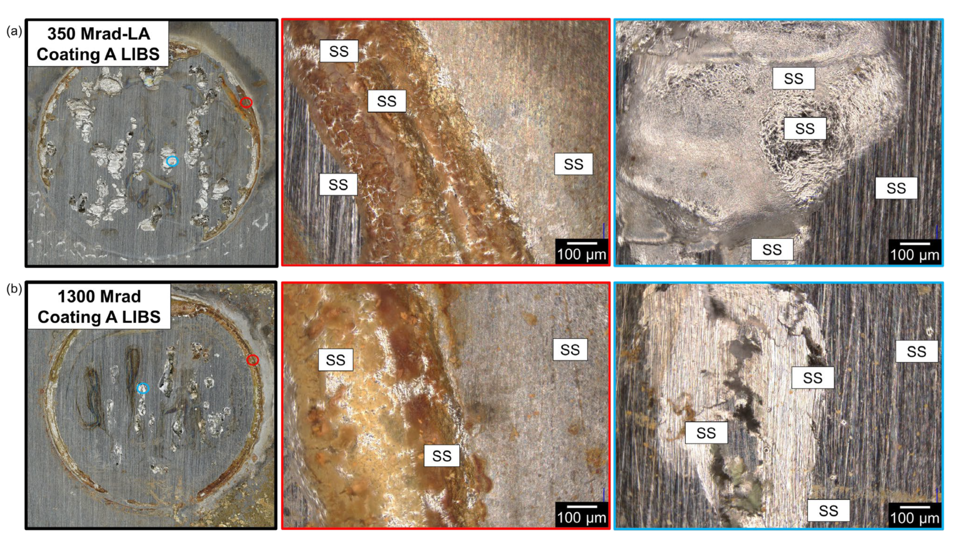
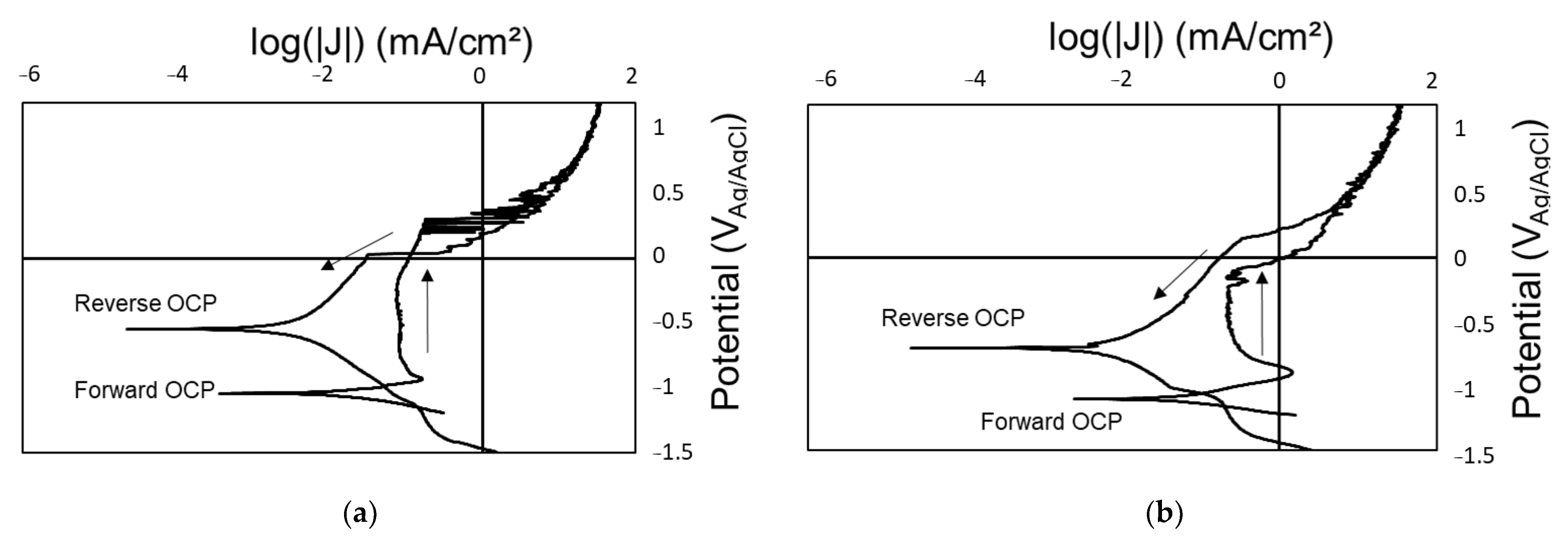
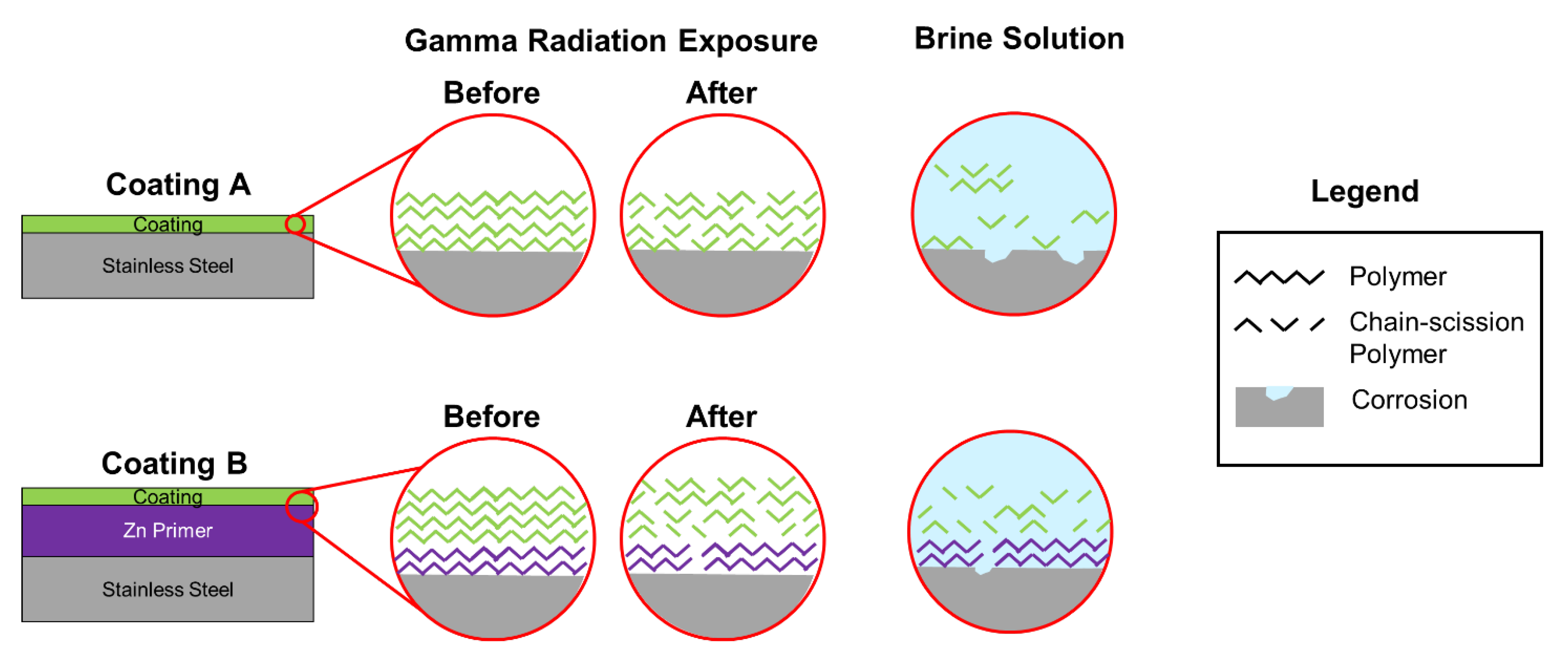
    The polymer–ceramic coating (Coating A) offered limited corrosion protection below 200 Mrad, but beyond this dose, all samples showed signs of corrosion. OCP values measured during the reverse scan were closer to that of a bare SS substrate. Additionally, LIBS identified SS with limited Si from the coating, suggesting degradation of the polymer coating. The organic portion of the polymer–silica coating is likely most susceptible to the total gamma radiation dose.
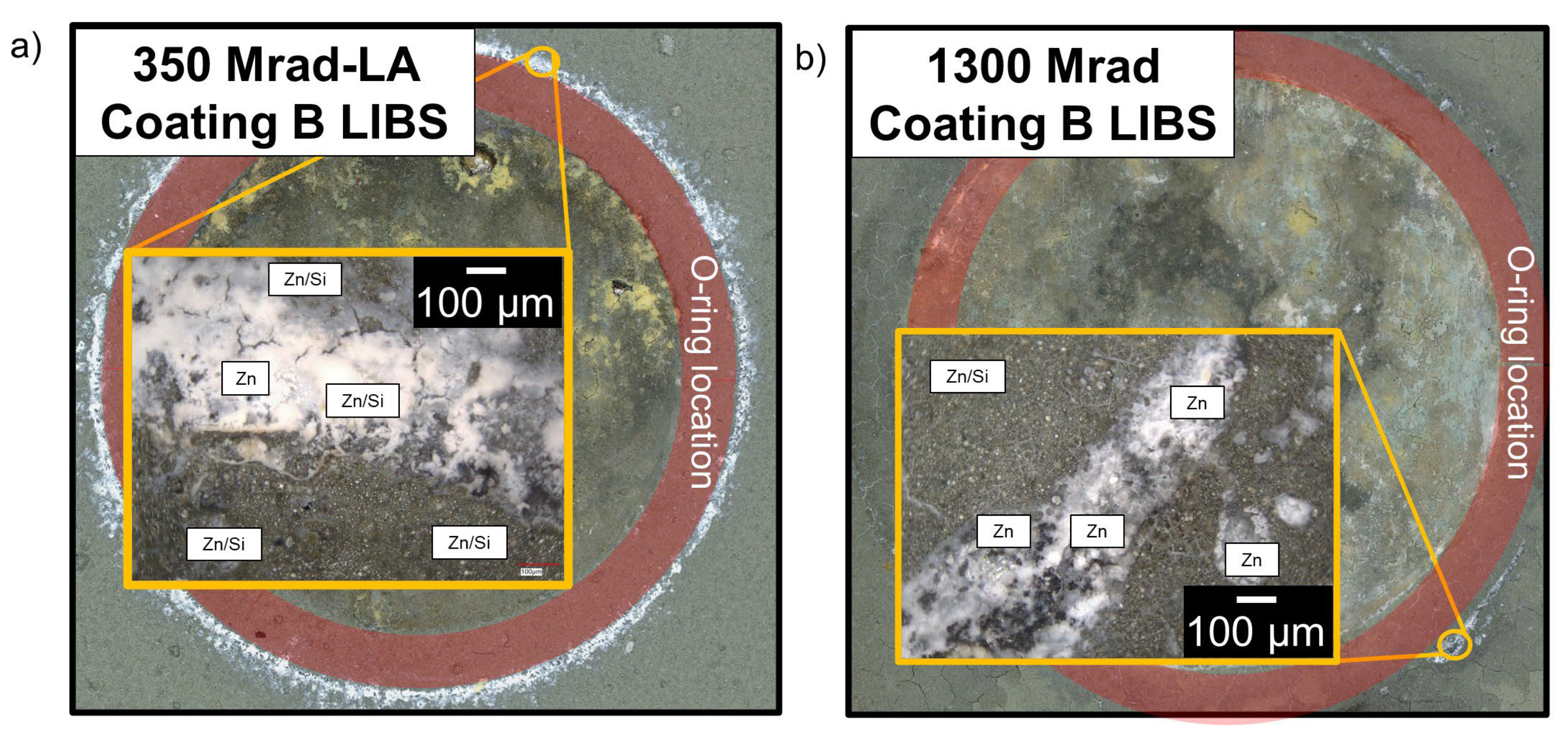
    The polymer–ceramic, Zn-rich primer coating (Coating B) showed improved corrosion resistance at elevated doses of gamma radiation compared to Coating A, ascribed to both the increased overall coating thickness and sacrificial nature of the secondary coating layer, the Zn-rich primer. OCP values obtained on the forward CPP are closer to that of Zn, whereas reverse scan OCP values suggest a mixed potential between Zn and SS, indicating some coating degradation and corrosion of the SS substrate.
  • As TGA/DSC data showed that polymer degradation began at 250 °C, and the Zn-rich primer coating displayed Zn oxidation beyond 420 °C, temperature did not play a significant role in coating degradation, with radiation exposure performed at 25 and 75 °C.
  • For the shutter array (SA) and linear array (LA) samples exposed to 350 Mrad, the change in dose rate from 176 to 1054 rad/s did not have a significant effect on coating performance.

Supplementary Materials

The following supporting information can be downloaded at https://www.mdpi.com/article/10.3390/coatings15030312/s1, Figure S1: Potentiodynamic polarizations and corresponding optical images for baseline (a) Coating A and (b) Coating B. Figure S2: Potentiodynamic polarizations and corresponding optical images for Coating A irradiated to (a) 100, (b) 200, (c) 350-LA, (d) 350-SA, (e) 730, and (f) 1300 Mrad. Figure S3: Potentiodynamic polarizations and corresponding optical images for Coating B irradiated to (a) 100, (b) 200, (c) 350-LA, (d) 350-SA, (e) 730, and (f) 1300 Mrad. Figure S4: Coating A LIBS analysis, 0 Mrad, 25 °C. Figure S5: Coating A LIBS analysis, 350-LA Mrad, 25 °C. Figure S6: Coating A LIBS analysis, 1300-LA Mrad, 25 °C. Figure S7: Coating B LIBS analysis, 0 Mrad, 25 °C. Figure S8: Coating B LIBS analysis, 350 Mrad-LA, 25 °C. Figure S9: Coating B LIBS analysis, 1300 Mrad, 25 °C.

Author Contributions

Conceptualization, A.K. and B.N.; methodology, A.K. and B.N.; validation, A.K. and B.N.; formal analysis, N.C.; investigation, A.R., D.H., G.D., M.M., S.V., T.M., B.N. and A.K.; resources, A.G.; writing—original draft preparation, N.C.; writing—review and editing, N.C.; supervision, A.K., B.N. and R.F.S.; project administration, A.K. and B.N. All authors have read and agreed to the published version of the manuscript.

Funding

This research received no external funding. Sandia National Laboratories is a multimission laboratory managed and operated by National Technology and Engineering Solutions of Sandia LLC, a wholly owned subsidiary of Honeywell International Inc., for the U.S. Department of Energy’s National Nuclear Security Administration under contract DE-NA-0003525. This article has been authored by an employee of National Technology & Engineering Solutions of Sandia, LLC under Contract No. DE-NA0003525 with the U.S. Department of Energy (DOE). The employee owns all rights, titles, and interests in and to the article and is solely responsible for its contents. The United States Government retains and the publisher, by accepting the article for publication, acknowledges that the United States Government retains a non-exclusive, paid-up, irrevocable, worldwide license to publish or reproduce the published form of this article or allow others to do so, for United States Government purposes. The DOE will provide public access to the results of federally sponsored research in accordance with the DOE Public Access Plan: https://www.energy.gov/downloads/doe-public-access-plan (accessed on the 4 March 2025). This paper describes objective technical results and analysis. Any subjective views or opinions that might be expressed in the paper do not necessarily represent the views of the U.S. Department of Energy or the United States Government.

Institutional Review Board Statement

Not applicable.

Informed Consent Statement

Not applicable.

Data Availability Statement

Data may be made available upon request.

Conflicts of Interest

Authors Natalie Click, Andrew Knight, Brendan Nation, Makeila Maguire, Samay Verma, Gavin DeBrun, Tyler McCready, Audrey Rotert, Don Hanson, Rebecca Filardo Schaller were employed by the company Sandia National Laboratories. Author Adam Goff was employed by the company Luna Labs.

References

  1. Katona, R.M.; Carpenter, J.C.; Knight, A.W.; Bryan, C.R.; Schaller, R.F.; Kelly, R.G.; Schindelholz, E.J. Importance of the hydrogen evolution reaction in magnesium chloride solutions on stainless steel. Corros. Sci. 2020, 177, 108935. [Google Scholar] [CrossRef]
  2. Katona, R.M.; Kelly, R.G.; Bryan, C.R.; Schaller, R.F.; Knight, A.W. Use of in situ Raman spectroelectrochemical technique to explore atmospheric corrosion in marine-relevant environments. Electrochem. Commun. 2020, 118, 106768. [Google Scholar] [CrossRef]
  3. Gao, H.; Lan, X.; Liu, L.; Xiao, X.; Liu, Y.; Leng, J. Study on performances of colorless and transparent shape memory polyimide film in space thermal cycling, atomic oxygen and ultraviolet irradiation environments. Smart Mater. Struct. 2017, 26, 095001. [Google Scholar] [CrossRef]
  4. Shulman, H.; Ginell, W.S. Nuclear and Space Radiation Effects on Materials; SP-8053; National Aeronautics and Space Administration: Washington, DC, USA, 1970. [Google Scholar]
  5. Schaller, R.; Knight, A.W.; Bryan, C.R.; Nation, B.L.; Montoya, T.; Katona, R.M. SNF Interim Storage Canister Corrosion and Surface Environment Investigations (FY2020 Status Report) M2SF-21SN010207055 (No. SAND-2020-12663R); Sandia National Lab. (SNL-NM): Albuquerque, NM, USA, 2020. [Google Scholar]
  6. Nation, B.L.; Knight, A.W.; Maguire, M.; Verma, S.; Click, N.; Debrun, G.; McCready, T.; Katona, R.; Schaller, R.F.; Bryan, C.R. FY23 Status: Corrosion-Resistant Coatings on Spent Nuclear Fuel Canisters to Mitigate and Repair Potential Stress Corrosion Cracking M3SF-23SN010207052 (No. SAND-2023-09205R); Sandia National Lab. (SNL-NM): Albuquerque, NM, USA, 2023. [Google Scholar]
  7. Karasz, E.K.; Montoya, T.D.; Taylor, J.M.; Ross, K.A.; Schaller, R.F. Accelerated corrosion testing of cold spray coatings on 304L in chloride environments. Front. Met. Alloys 2022, 1, 1021000. [Google Scholar] [CrossRef]
  8. Qu, H.J.; Srinivasan, J.; Zhao, Y.; Mao, K.S.; Taylor, J.M.; Marino, G.; Montoya, T.; Johnson, K.; Locke, J.S.; Schaller, R.; et al. Stress corrosion cracking mechanism of cold spray coating on a galvanically similar substrate. Mater. Sci. Eng. A 2022, 849, 143404. [Google Scholar] [CrossRef]
  9. Yeom, H.; Sridharan, K. Cold spray technology in nuclear energy applications: A review of recent advances. Ann. Nucl. Energy 2021, 150, 107835. [Google Scholar] [CrossRef]
  10. Yeom, H.; Dabney, T.; Pocquette, N.; Ross, K.; Pfefferkorn, F.E.; Sridharan, K. Cold spray deposition of 304L stainless steel to mitigate chloride-induced stress corrosion cracking in canisters for used nuclear fuel storage. J. Nucl. Mater. 2020, 538, 152254. [Google Scholar] [CrossRef]
  11. Wang, W.; Tamakloe, S.; Deng, Z.; Li, L.; Cai, W.; Lu, K. Effects of processing temperature on the corrosion and tribocorrosion resistance of perhydropolysilazane-derived coatings on AISI 304 steel. Surf. Coat. Technol. 2022, 439, 128463. [Google Scholar] [CrossRef]
  12. Du, Y.J.; Damron, M.; Tang, G.; Zheng, H.; Chu, C.J.; Osborne, J.H. Inorganic/organic hybrid coatings for aircraft aluminum alloy substrates. Prog. Org. Coat. 2001, 41, 226–232. [Google Scholar] [CrossRef]
  13. Zheng, S.; Li, J. Inorganic-organic sol gel hybrid coatings for corrosion protection of metals. J. Sol-Gel Sci. Technol. 2010, 54, 174–187. [Google Scholar] [CrossRef]
  14. Wang, D.; Bierwagen, G.P. Sol-gel coatings on metals for corrosion protection. Prog. Org. Coat. 2009, 64, 327–338. [Google Scholar] [CrossRef]
  15. Ramezanzadeh, B.; Arman, S.Y.; Mehdipour, M. Anticorrosion properties of an epoxy zinc-rich composite coating reinforced with zinc, aluminum, and iron oxide pigments. J. Coat. Technol. Res. 2014, 11, 727–737. [Google Scholar] [CrossRef]
  16. McMahon, M.E.; Burns, J.T.; Scully, J.R. Development of new criteria for evaluating the effectiveness of Zn-rich primers in protecting Al-Mg alloys. Prog. Org. Coat. 2019, 135, 392–409. [Google Scholar] [CrossRef]
  17. McMahon, M.E.; Santucci Jr, R.J.; Glover, C.F.; Kannan, B.; Walsh, Z.R.; Scully, J.R. A Review of Modern Assessment Methods for Metal and Metal-Oxide Based Primers for Substrate Corrosion Protection. Front. Mater. 2019, 6, 190. [Google Scholar] [CrossRef]
  18. McMahon, M.E.; Scully, J.R.; Burns, J.T. Mitigation of Intergranular Cracking in Al-Mg Alloys via Zn-Based Electrode Potential Control in Sodium Chloride Solution. Corrosion 2019, 75, 911–928. [Google Scholar] [CrossRef]
  19. Panossian, Z.; Mariaca, L.; Morcillo, M.; Flores, S.; Rocha, J.; Peña, J.J.; Herrera, F.; Corvo, F.; Sanchez, M.; Rincon, O.T.; et al. Steel cathodic protection afforded by zinc, aluminium and zinc/aluminium alloy coatings in the atmosphere. Surf. Coat. Technol. 2005, 190, 244–248. [Google Scholar] [CrossRef]
  20. Abdeldaym, A.; Magida, M.M.; Elnahas, H.H. Preparation and evaluation of structural, optical, dielectric and thermal characteristics of unirradiated and irradiated polyurethane/magnesium silicate composites. J. Mater. Sci. Mater. Electron. 2021, 32, 5755–5769. [Google Scholar] [CrossRef]
  21. Gorna, K.; Gogolewski, S. The effect of gamma radiation on molecular stability and mechanical properties of biodegradable polyurethanes for medical applications. Polym. Degrad. Stab. 2003, 79, 465–474. [Google Scholar] [CrossRef]
  22. Kim, J.H.; Hwang, J.H.; Suh, J.; Tongay, S.; Kwon, S.; Hwang, C.C.; Wu, J.; Park, J.Y. Work function engineering of single layer graphene by irradiation-induced defects. Appl. Phys. Lett. 2013, 103, 171604. [Google Scholar]
  23. Wang, L.; Wang, K.; Erkan, N.; Yuan, Y.; Chen, J.; Nie, B.; Li, F.; Okamoto, K. Metal material surface wettability increase induced by electron beam irradiation. Appl. Surf. Sci. 2020, 511, 145555. [Google Scholar] [CrossRef]
  24. Velo-Gala, I.; Lopez-Penalver, J.J.; Sánchez-Polo, M.; Rivera-Utrilla, J. Surface modifications of activated carbon by gamma irradiation. Carbon 2014, 67, 236–249. [Google Scholar] [CrossRef]
  25. Clough, R. High-energy radiation and polymers: A review of commercial processes and emerging applications. Nucl. Instrum. Methods Phys. Res. Sect. B Beam Interact. Mater. At. 2001, 185, 8–33. [Google Scholar] [CrossRef]
  26. Ito, S.; Miyazaki, Y.; Hirai, N.; Ohki, Y. Effects of gamma irradiation on the degradation of silicone rubber by steam exposure. J. Nucl. Sci. Technol. 2021, 58, 166–172. [Google Scholar] [CrossRef]
  27. Zimmermann, J.; Schalm, T.; Sadeghi, M.Z.; Schröder, K.U. Empirical investigations on the effects of ionizing radiation on epoxy structural adhesives and resins: An overview. Int. J. Adhes. Adhes. 2022, 117, 103014. [Google Scholar] [CrossRef]
  28. Knight, A.; Nation, B.; Maguire, M.; Schaller, R.; Bryan, C. Corrosion-Resistant Coatings on Spent Nuclear Fuel Canisters to Mitigate and Repair Potential Stress Corrosion Cracking (FY22 Status) M3SF-22SN010207062 (No. SAND2022-14233R); Sandia National Lab. (SNL-NM): Albuquerque, NM, USA, 2022. [Google Scholar]
  29. Dodge, H. Gamma Irradiation Facility (No. SAND2021-12046R); Sandia National Lab. (SNL-NM): Albuquerque, NM, USA, 2021. [Google Scholar]
  30. ASTM-D4082; Standard Test Method for Effects of Gamma Radiation on Coatings for Use in Nuclear Power Plants. ASTM International: West Conshohocken, PA, USA, 2023; pp. 1–2.
  31. ASTM D659-86e1; Method of Evaluating Degree of Chalking of Exterior Paints. ASTM International: West Conshohocken, PA, USA, 2021; pp. 70–71.
  32. ASTM D661-93(2019); Standard Test Method for Evaluating Degree of Cracking of Exterior Paints. ASTM International: West Conshohocken, PA, USA, 2019; pp. 1–3.
  33. ASTM D714-02(2017); Standard Test Method for Evaluating Degree of Blistering Paints. ASTM International: West Conshohocken, PA, USA, 2017; pp. 1–6.
  34. ASTM D772-24; Standard Test Method for Evaluating Degree of Flaking (Scaling) of Exterior Paints. ASTM International: West Conshohocken, PA, USA, 2024; pp. 1–5.
  35. Mouanga, M.; Berçot, P. Comparison of corrosion behaviour of zinc in NaCl and in NaOH solutions; Part II: Electrochemical analyses. Corros. Sci. 2010, 52, 3993–4000. [Google Scholar] [CrossRef]
  36. El-Sayed, A.; Shilkamy, H.; Elrouby, M. The passivity breakdown of zinc antimony alloy as an anode in the alkaline batteries. Sci. Rep. 2022, 12, 18925. [Google Scholar] [CrossRef]
  37. Van Loo, M.; Laiderman, D.D.; Bruhn, R.R. Filiform Corrosion. Corrosion 1953, 9, 277–283. [Google Scholar] [CrossRef]
  38. Frankel, G.S. Pitting Corrosion in ASM International; ASM Handbook Online: Materials Park, OH, USA, 2003; pp. 236–241. [Google Scholar] [CrossRef]
  39. Hassanajili, S.; Khademi, M.; Keshavarz, P. Influence of various types of silica nanoparticles on permeation properties of polyurethane/silica mixed matrix membranes. J. Membr. Sci. 2014, 453, 369–383. [Google Scholar] [CrossRef]
  40. Xu, L.; Fu, Y.; Du, M. Investigation on Structures and Properties of Shape Memory Polyurethane/Silica Nanocomposites. Chin. J. Chem. 2011, 29, 703–710. [Google Scholar] [CrossRef]
  41. Kalogeras, I.M. Encyclopedia of Polymer Blends, 1st ed.; Wiley: Hoboken, NJ, USA, 2016; Volume 3. [Google Scholar]
  42. Jang, E.S.; Khan, S.B.; Seo, J.; Akhtar, K.; Choi, J.; Kim, K.I.; Han, H. Synthesis and characterization of novel UV-Curable PU-Si hybrids: Influence of silica on thermal, mechanical, and water sorption properties of polyurethane acrylates. Macromol. Res. 2011, 19, 1006–1013. [Google Scholar] [CrossRef]
  43. Zaborowska, A.; Wyszkowska, E.; Clozel, M.; Vanazzi, M.; Di Fonzo, F.; Turek, M.; Jóźwik, I.; Kosińska, A.; Jagielski, J. Influence of ion irradiation on the nanomechanical properties of thin alumina coatings deposited on 316L SS by PLD. Surf. Coat. Technol. 2020, 386, 125491. [Google Scholar] [CrossRef]
  44. García Ferré, F.; Mairov, A.; Ceseracciu, L.; Serruys, Y.; Trocellier, P.; Baumier, C.; Kaïtasov, O.; Brescia, R.; Gastaldi, D.; Vena, P.; et al. Radiation endurance in Al2O3 nanoceramics. Sci. Rep. 2016, 6, 33478. [Google Scholar] [CrossRef]
  45. Shintani, H.; Nakamura, A. Degradation and cross-linking of polyurethane irradiated by gamma-rays. Polym. Degrad. Stab. 1991, 32, 191–208. [Google Scholar] [CrossRef]
  46. Pierpoint, S.; Silverman, J.; Al-Sheikhly, M. Effects of ionizing radiation on the aging of polyester based polyurethane binder. Radiat. Phys. Chem. 2001, 62, 163–169. [Google Scholar] [CrossRef]
  47. Ferreño, D.; Mañanes, A.; Rábago, D.; Casado, J.A.; González, J.A.; Gómez, S.; Carrascal, I.A.; Ruiz, E.; Diego, S.; Gómez, F.; et al. Mechanical behavior and microstructural changes in polyurethane exposed to high doses of X rays, gamma rays or neutron irradiation. Polym. Test. 2018, 67, 359–369. [Google Scholar] [CrossRef]
  48. Sui, H.; Liu, X.; Zhong, F.; Li, X.; Wang, B.; Ju, X. Relationship between free volume and mechanical properties of polyurethane irradiated by gamma rays. J. Radioanal. Nucl. Chem. 2014, 300, 701–706. [Google Scholar] [CrossRef]
  49. Shintani, H.; Kikuchi, H.; Nakamura, A. Effects of gamma-ray irradiation on the change of characteristics of polyurethane. J. Appl. Polym. Sci. 1990, 41, 661–675. [Google Scholar] [CrossRef]
  50. Thierry, D.; Larché, N.; Leballeur, C.; Wijesinghe, S.L.; Zixi, T. Corrosion potential and cathodic reduction efficiency of stainless steel in natural seawater. Mater. Corros. 2015, 66, 453–458. [Google Scholar]
  51. Saeedikhani, M.; Wijesinghe, S.L.; Blackwood, D.J. Barrier and sacrificial protection mechanisms of zinc rich primers. Eng. J. 2019, 23, 223–233. [Google Scholar] [CrossRef]
  52. Takahashi, H.; Hashimoto, N. Radiation-induced segratation and grain boundary migration in Fe-Cr-Ni model alloy under irradiation. Mater. Trans. JIM 1993, 34, 1027–1030. [Google Scholar]
  53. Nakata, K.; Katano, Y.; Masaoka, I.; Shiraishi, K. Grain boundary migration during electron irradiation in austenitic stainless steels. J. Nucl. Mater. 1985, 133–134, 575–579. [Google Scholar] [CrossRef]
  54. Zheng, Z.B.; Zheng, Y.G. Effects of surface treatments on the corrosion and erosion-corrosion of 304 stainless steel in 3.5% NaCl solution. Corros. Sci. 2016, 112, 657–668. [Google Scholar] [CrossRef]
Figure 1. Schematic of example experimental analysis.
Coatings 15 00312 g001
Figure 2. TGA (solid) and DSC (dashed) curves for Coatings A and B with conditions of 100 mL/min air flow and a temperature range of 25–827 °C. Solid lines correspond to weight variation % (solid arrow indicating corresponding left axis) while dashed lines correspond to heat flow (dashed arrow indicating corresponding right axis).
Coatings 15 00312 g002
Figure 3. Baseline CPP scans in 0.6 M NaCl solution for Baseline Coating A (a) and Baseline Coating B (b) in the non-irradiated condition (0 Mrad). Arrows indicate direction of scan.
Coatings 15 00312 g003
Figure 4. LIBS analysis of Coatings (a) A and (b) B, interrogating their chemical compositions in select locations (indicated by red and blue outlines) following CPP in 0.6 M NaCl solution and in the non-irradiated condition (0 Mrad).
Coatings 15 00312 g004
Figure 5. TGA weight variation % (solid lines, solid arrow indicating corresponding left axis) and DSC heat flow (dashed lines, dashed arrow indicating corresponding right axis) for Coatings A and B post-irradiation (Coating A—Mrad and Coating B—1300 Mrad) and CPP in 0.6 M NaCl solution. Conditions used were 100 mL/min air flow, 24–800 °C.
Coatings 15 00312 g005
Figure 6. CPP scan for Coating A post exposure to (a) 350 Mrad 25 °C LA and (b) 1300 Mrad 77 °C SA gamma radiation. Arrows indicate direction of scan.
Coatings 15 00312 g006
Figure 7. (a) OCP and (b) Eb data for Coating A samples vs. radiation dose.
Coatings 15 00312 g007
Figure 8. LIBS analysis of Coating A interrogating the chemical compositions in select locations (identified by the corresponding red and blue outlines) following exposure to (a) 350 Mrad 25 °C LA and (b) 1300 Mrad 77 °C SA and CPP analysis.
Coatings 15 00312 g008
Figure 9. CPP scan for Coating B post exposure to (a) 350 Mrad 25 °C LA and (b) 1300 Mrad 77 °C SA gamma radiation. Arrows indicate direction of scan.
Coatings 15 00312 g009
Figure 10. (a) OCP and (b) Eb data for Coating B samples vs. radiation dose.
Coatings 15 00312 g010
Figure 11. LIBS analysis of Coating B, interrogating the chemical compositions in select locations (identified by the corresponding red and blue outlines) following exposure to (a) 350 Mrad 25 °C LA and (b) 1300 Mrad 75 °C SA and subsequent CPP.
Coatings 15 00312 g011
Figure 12. LIBS analysis of the white ring that formed on the outside of the test area on Coating B showing a Zn-rich precipitate for samples that were exposed to (a) 350 Mrad 25 °C LA and (b) 1300 Mrad 75 °C SA.
Coatings 15 00312 g012
Figure 13. Schematic of proposed mechanism of coating degradation upon exposure to radiation + corrosive brine solution (not to scale).
Coatings 15 00312 g013
Table 1. Exposures performed at the Gamma Irradiation Facility.
Exposure
Cell
Average Dose
Rate
Total Dose
(Mrad)
Temperature During Exposure (°C)Duration of Exposure (Hours)
Linear Array176 rad/s10525165
21125333
35025575
Shutter Array1054 rad/s3517792
72477196
130577379
Disclaimer/Publisher’s Note: The statements, opinions and data contained in all publications are solely those of the individual author(s) and contributor(s) and not of MDPI and/or the editor(s). MDPI and/or the editor(s) disclaim responsibility for any injury to people or property resulting from any ideas, methods, instructions or products referred to in the content.

