
Microstructure and Cracking Behavior of a Four-Layer Thermal Barrier Coating After Thermal Cycle Test

Abstract
1. Introduction
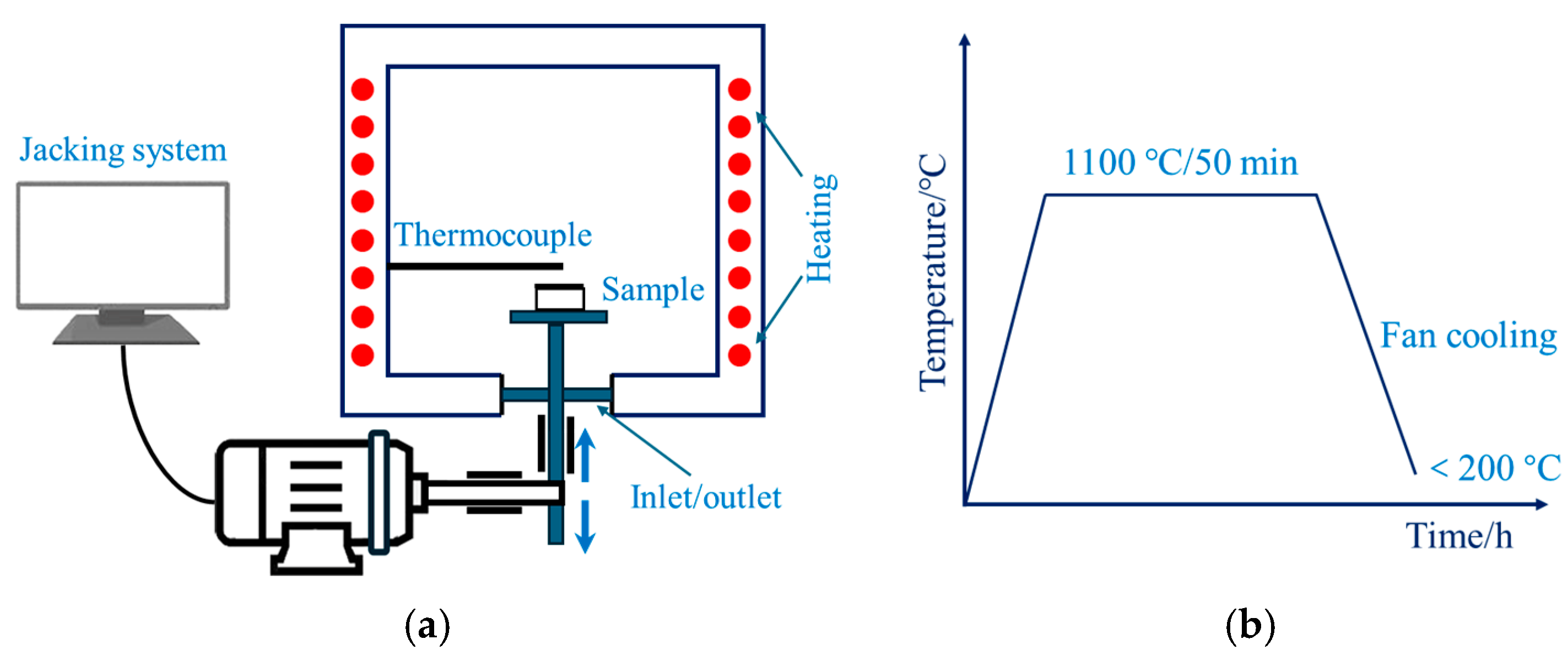
2. Methodology
3. Results and Discussion
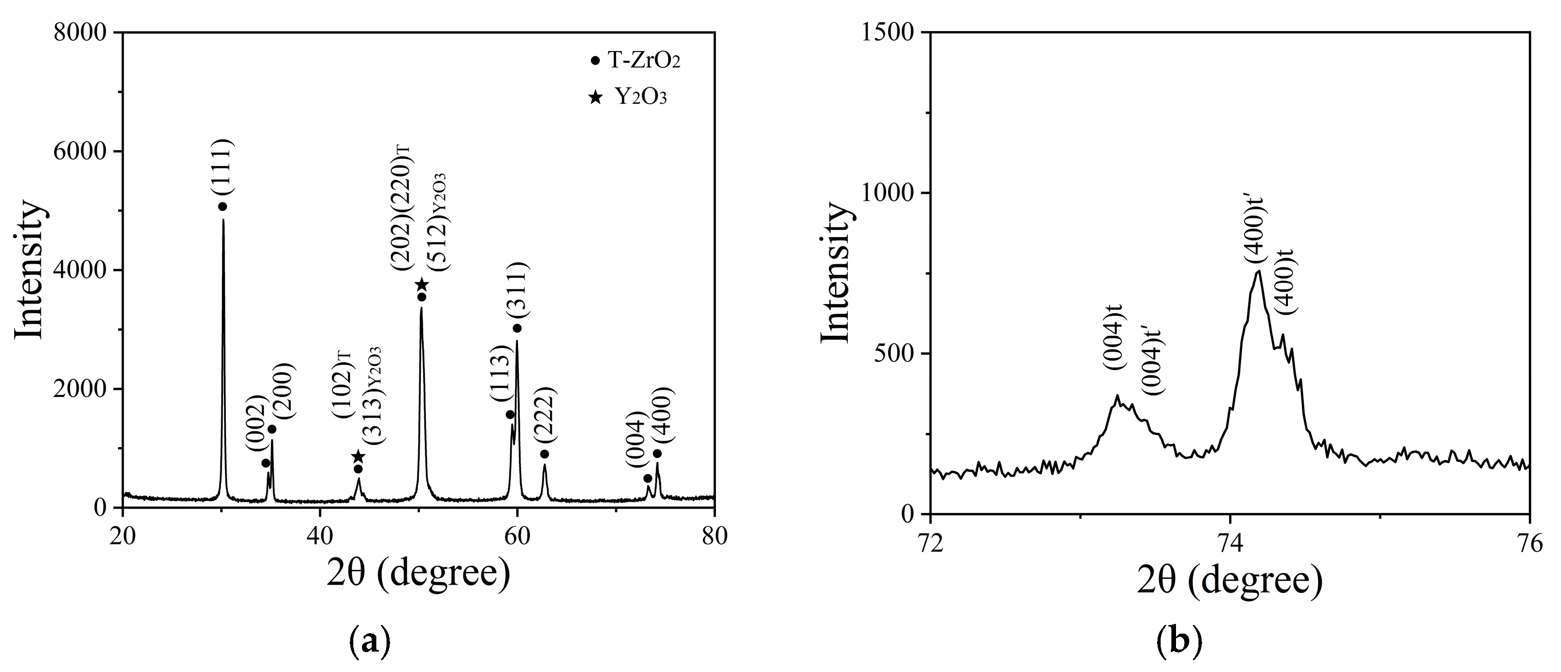
3.1. Phase Composition of the As-Sprayed Sample
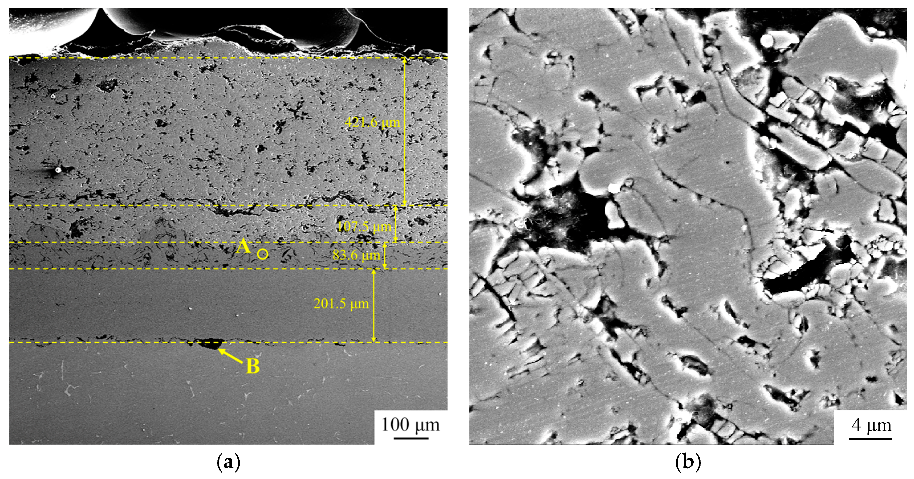
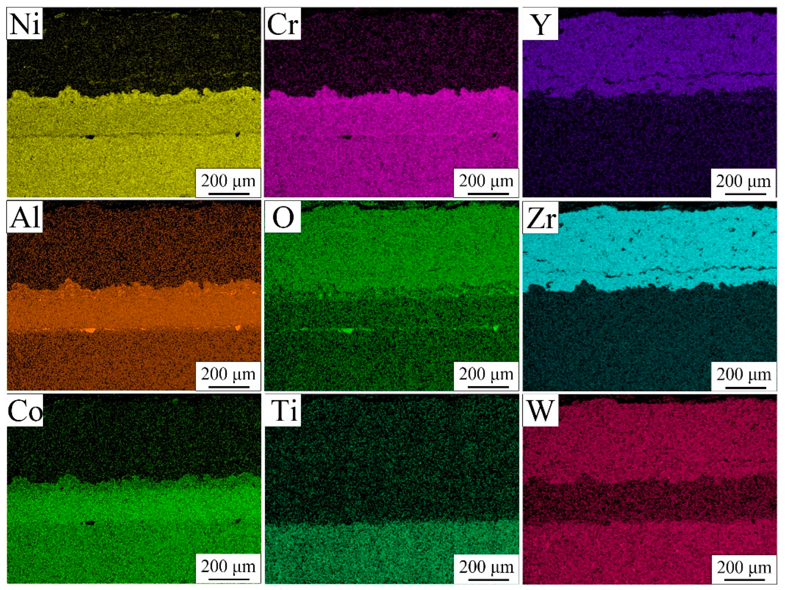
3.2. Microstructure of TBC Before Thermal Cycle Test
3.3. Bond Strength of the TBC
3.4. Phase Composition of the TBC After Thermal Cycle Test
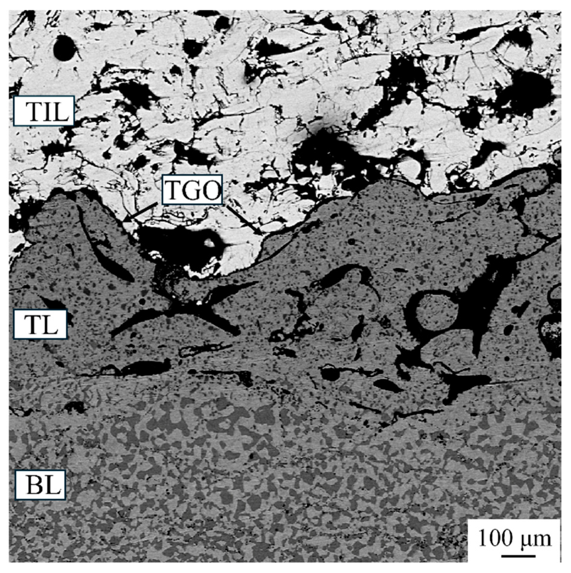
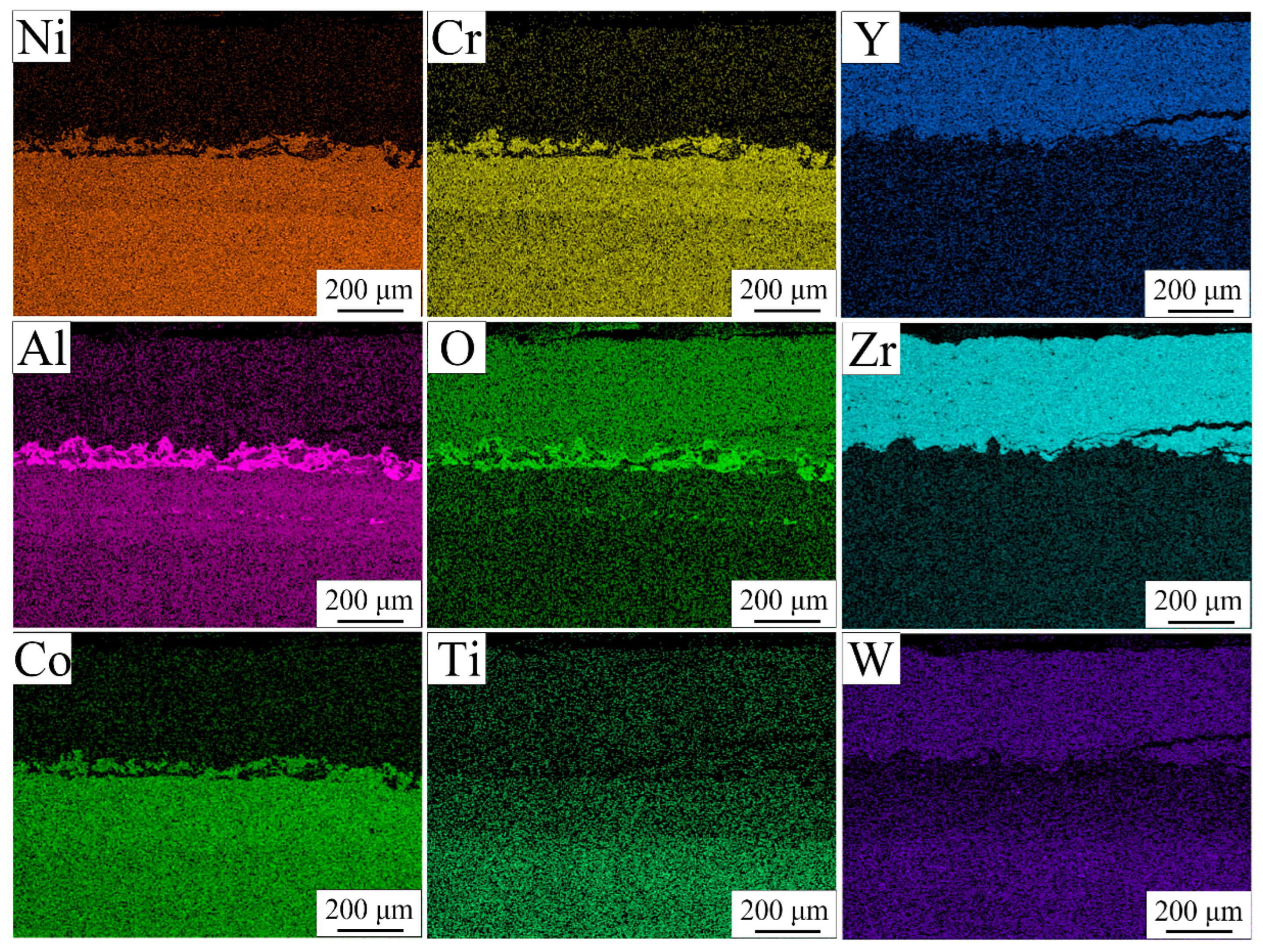
3.5. Microstructure of TBC After Thermal Cycle Test
3.6. Indentation
4. Conclusions
- (1)
- The TBC system is designed with a four-layer structure consisting of a TBC smooth layer, a TBC inner layer, a transition layer, and a bottom layer, with an average bond strength of 73.74 MPa. The TBC consists of tetragonal t and t′ phases, as well as monoclinic yttrium oxide.
- (2)
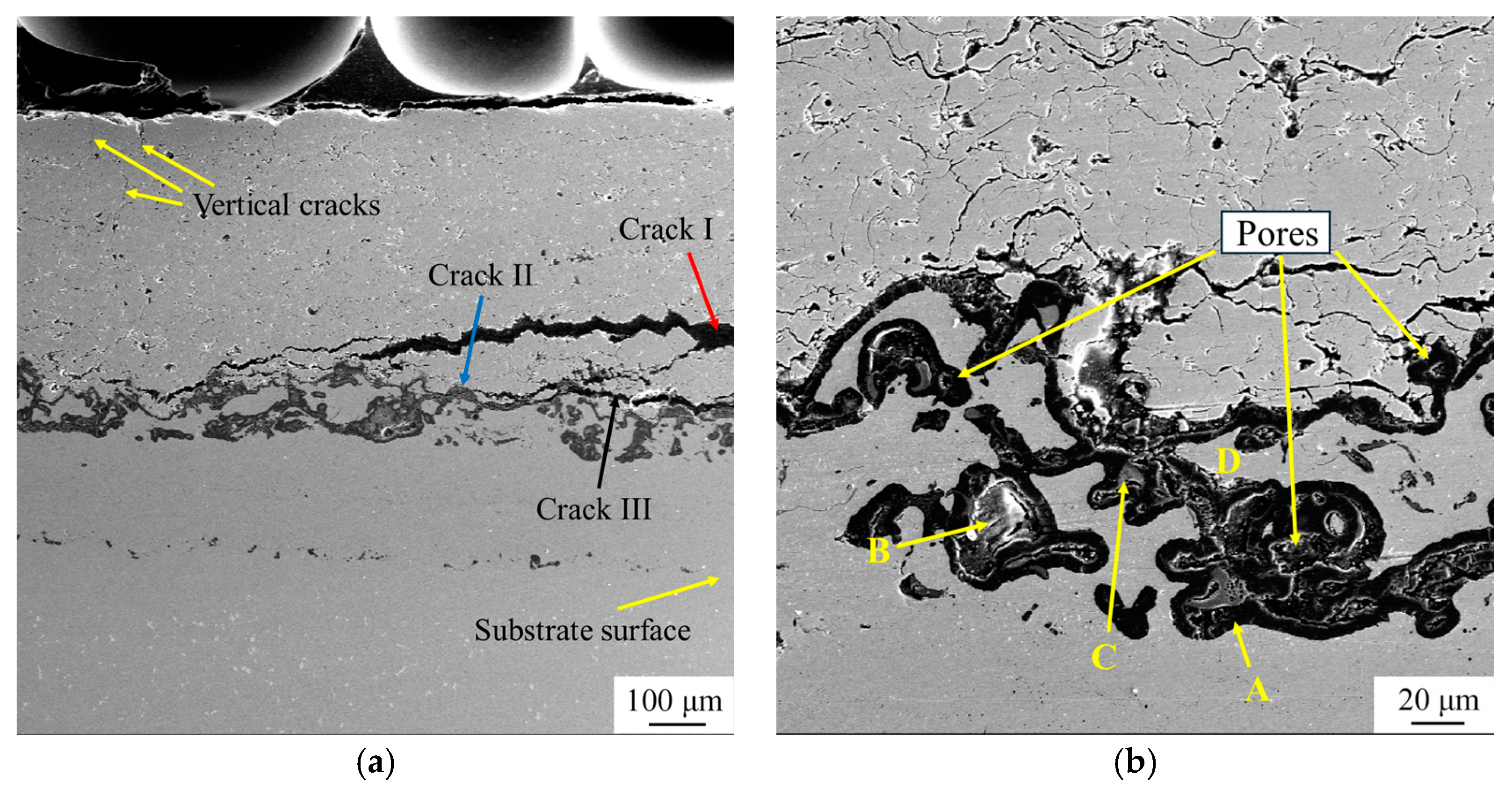
- After 500 thermal cycles, the m-ZrO2 phase was formed through the phase transformation of t′-ZrO2 to m-ZrO2 and c-ZrO2 during thermal cycle test. A large number of bulk TGO containing chromia, spinel, and yttrium aluminates were formed around pores within the transition layer. Furthermore, the increase rate of the TGO layer was relatively low, which may be attributed to the formation of bulk TGO around pores within the transition layer.
- (3)
- Large horizontal cracks are likely to form at the TSL/TIL and TIL/TL interfaces, while vertical cracks tend to occur near the surface of the TSL, and the propagation rate is relatively low. The propagation of horizontal cracks is the primary cause of failure in this four-layer structure.
- (4)
- After the thermal cycle test, the porosity of the TSL decreased significantly, from 7.17% to 0.76%, and the nanoindentation test revealed that there was a slight increase in hardness and reduced modulus.
Author Contributions
Funding
Institutional Review Board Statement
Informed Consent Statement
Data Availability Statement
Conflicts of Interest
Abbreviations
| BC | Bond coat |
| TGO | Thermally grown oxide |
| TC | Top ceramic coat |
| CTE | Coefficient of thermal expansion |
| APS | Atmospheric Plasma Spraying |
| EB-PVD | Electron Beam Physical Vapor Deposition |
| CVD | Chemical Vapor Deposition |
| BL | Bottom layer |
| TL | Transition layer |
| TIL | TBC inner layer |
| TSL | TBC smooth layer |
References
- Thakare, J.G.; Pandey, C.; Mahapatra, M.M.; Mulik, R.S. Thermal Barrier Coatings—A State of the Art Review. Met. Mater. Int. 2021, 27, 1947–1968. [Google Scholar] [CrossRef]
- Lakiza, S.M.; Grechanyuk, M.I.; Ruban, O.K.; Redko, V.P.; Glabay, M.S.; Myloserdov, O.B.; Dudnik, O.V.; Prokhorenko, S.V. Thermal Barrier Coatings: Current Status, Search, and Analysis. Powder Metall. Met. Ceram. 2018, 57, 82–113. [Google Scholar] [CrossRef]
- Liu, F.; Zhang, C.H.; Li, J.Q.; He, W.; Hou, X.H.; Zhang, H.Y.; Xie, H.M. Microstructure characteristics and deformation-induced crystalline-to-amorphous phase transformation in thermal barrier coatings during thermal cycling. Mater. Charact. 2024, 213, 114034. [Google Scholar] [CrossRef]
- Gurrappa, I.; Sambasiva Rao, A. Thermal barrier coatings for enhanced efficiency of gas turbine engines. Surf. Coat. Tech. 2006, 201, 3016–3029. [Google Scholar] [CrossRef]
- Ou, Y.X.; Wang, H.Q.; Ouyang, X.; Zhao, Y.Y.; Zhou, Q.; Luo, C.W.; Hua, Q.S.; Ouyang, X.P.; Zhang, S. Recent advances and strategies for high-performance coatings. Prog. Mater. Sci. 2023, 136, 101125. [Google Scholar] [CrossRef]
- Mehboob, G.; Liu, M.J.; Xu, T.; Hussain, S.; Mehboob, G.; Tahir, A. A review on failure mechanism of thermal barrier coatings and strategies to extend their lifetime. Ceram. Int. 2020, 46, 8497–8521. [Google Scholar] [CrossRef]
- Vaßen, R.; Jarligo, M.O.; Steinke, T.; Mack, D.E.; Stover, D. Overview on advanced thermal barrier coatings. Surf. Coat. Technol. 2010, 205, 938–942. [Google Scholar] [CrossRef]
- Wu, Y.Y.; Luo, H.; Cai, C.Y.; Wang, Y.G.; Zhou, Y.C.; Yang, L.; Zhou, G.W. Comparison of CMAS corrosion and sintering induced microstructural characteristics of APS thermal barrier coatings. J. Mater. Sci. Technol. 2019, 35, 440–447. [Google Scholar] [CrossRef]
- Moskal, G.; Jasik, A.; Mikuśkiewicz, M.; Jucha, S. Thermal resistance determination of Sm2Zr2O7+8YSZ composite type of TBC. Appl. Surf. Sci. 2020, 515, 145998. [Google Scholar] [CrossRef]
- Zhu, W.; Zhang, Z.B.; Yang, L.; Zhou, Y.C.; Wei, Y.G. Spallation of thermal barrier coatings with real thermally grown oxide morphology under thermal stress. Mater. Des. 2018, 146, 180–193. [Google Scholar] [CrossRef]
- Zhu, D.M.; Nesbitt, J.A.; Barrett, C.A.; Mccue, T.R.; Miller, R.A. Furnace cyclic oxidation behavior of multicomponent low conductivity thermal barrier coatings. J. Therm. Spray Technol. 2004, 13, 84–92. [Google Scholar] [CrossRef]
- Vassen, R.; Cao, X.Q.; Tietz, F.; Basu, D.; Stöver, D. Zirconates as new materials for thermal barrier coatings. J. Am. Ceram. Soc. 2000, 83, 2023–2028. [Google Scholar] [CrossRef]
- Wortman, D.J.; Nagaraj, B.A.; Duderstadt, E.C. Thermal barrier coatings for gas turbine use. Mater. Sci. Eng. 1989, 120–121, 433–440. [Google Scholar] [CrossRef]
- Li, B.; Fan, X.L.; Zhou, K.; Wang, T.J. Effect of oxide growth on the stress development in double-ceramic-layer thermal barrier coatings. Ceram. Int. 2017, 43, 14763–14774. [Google Scholar] [CrossRef]
- Zhou, F.F.; Wang, Y.; Wang, L.; Cui, Z.Y.; Zhang, Z.G. High temperature oxidation and insulation behavior of plasma-sprayed nanostructured thermal barrier coatings. J. Alloy. Compd. 2017, 704, 614–623. [Google Scholar] [CrossRef]
- Vaßen, R.; Traeger, F.; Stöver, D. New Thermal Barrier Coatings Based on Pyrochlore/YSZ Double-Layer Systems. Int. J. Appl. Ceram. Technol. 2004, 26, 351–361. [Google Scholar] [CrossRef]
- Gok, M.G.; Goller, G. Production and characterisation of GZ/CYSZ alternative thermal barrier coatings with multilayered and functionally graded designs. J. Eur. Ceram. Soc. 2016, 36, 1755–1764. [Google Scholar] [CrossRef]
- Han, M.; Huang, J.H.; Chen, S.H. The influence of interface morphology on the stress distribution in double-ceramic-layer thermal barrier coatings. Ceram. Int. 2015, 41, 4312–4325. [Google Scholar] [CrossRef]
- Doleker, K.M.; Ozgurluk, Y.; Karaoglanli, A.C. TGO growth and kinetic study of single and double layered TBC systems. Surf. Coat. Technol. 2021, 415, 127135. [Google Scholar] [CrossRef]
- Huang, Y.P.; Wei, Z.Y.; Cai, H.N.; Liu, Y.; Han, X.C. The effects of TGO growth stress and creep rate on TC/TGO interface cracking in APS thermal barrier coatings. Ceram. Int. 2021, 47, 24760–24769. [Google Scholar] [CrossRef]
- Li, W.S.; Li, Z.Y.; An, G.S.; Cheng, B.; Song, Q.; Sun, J.Q.; Vaganov, V.; Wang, G.M.; Goransky, G. Isothermal oxidation TGO growth behaviors of laser-remolten LZO/YSZ thermal barrier coatings. Coatings 2022, 12, 107. [Google Scholar] [CrossRef]
- Yang, K.H.; Shi, J.M.; Liu, L.Q.; Chen, X.L.; Xu, W.H.; Zhao, Z.; Tian, F.Q.; Zhang, X.C. Ablation behavior and delamination mechanism of air plasma sprayed (Gd, Yb) doped YSZ double ceramic layer thermal barrier coatings at 1500 °C. Surf. Coat. Technol. 2025, 496, 131679. [Google Scholar] [CrossRef]
- Wei, Z.Y.; Cheng, B.; Wang, J.; Liu, M.J.; Cai, H.N. Extend the thermal cyclic lifetime of La2Zr2O7/YSZ DCL TBCs by reducing modulus design on a toughening ceramic surface. Surf. Coat. Technol. 2019, 374, 134–143. [Google Scholar] [CrossRef]
- Vaßen, R.; Bakan, E.; Mack, D.; Schwartz-Lückge, S.; Sebold, D.; Sohn, Y.J.; Zhou, D.P.; Guillon, O. Performance of YSZ and Gd2Zr2O7/YSZ double layer thermal barrier coatings in burner rig tests. J. Eur. Ceram. Soc. 2020, 40, 480–490. [Google Scholar] [CrossRef]
- Zhou, Y.; Xie, F.; Cheng, L.F.; Xu, H.; Wang, X.Y.; Yu, D.Q. Optimize Design and Manufacture of 130MW Gas Turbine First Stage Blade. In Proceedings of the 2022 IEEE 6th Conference on Energy Internet and Energy System Integration, Chengdu, China, 11–13 November 2022; pp. 2749–2754. [Google Scholar]
- Di Girolamo, G.; Marra, F.; Blasi, C.; Serra, E.; Valente, T. Microstructure, mechanical properties and thermal shock resistance of plasma sprayed nanostructured zirconia coatings. Ceram. Int. 2011, 37, 2711–2717. [Google Scholar] [CrossRef]
- Shi, M.C.; Xue, Z.L.; Zhang, Z.Y.; Ji, X.J.; Byon, E.S.; Zhang, S.T. Effect of Spraying Powder Characteristics on Mechanical and Thermal Shock Properties of Plasma-Sprayed YSZ Thermal Barrier Coating. Surf. Coat. Tech. 2020, 395, 125913. [Google Scholar] [CrossRef]
- Li, C.J.; Li, Y.; Yang, G.J.; Li, C.X. A Novel Plasma-Sprayed Durable Thermal Barrier Coating with a Well-Bonded YSZ Interlayer Between Porous YSZ and Bond Coat. J. Therm. spray Tech. 2012, 21, 383–390. [Google Scholar] [CrossRef]
- Lu, X.; Huang, S.; Shi, T.; Pang, X. Modelling on How Topcoat/Bond Coat Micro-Rough Interface and Nearby Voids Affect the Stress Distribution in Thermal Barrier Coating Systems in Quenching Process. Coatings 2025, 15, 97. [Google Scholar] [CrossRef]
- Wei, Z.Y.; Cai, H.N.; Feng, R.X.; Zhang, H. The Combined Effect of Creep and TGO Growth on the Cracking Driving Force in a Plasma-Sprayed Thermal Barrier System. J. Therm. Spray Technol. 2019, 28, 1000–1016. [Google Scholar] [CrossRef]
- Rabiei, A.; Evans, A.G. Failure Mechanisms Associated with the Thermally Grown Oxide in Plasma-sprayed Thermal Barrier Coatings. Acta Mater. 2000, 48, 3963–3976. [Google Scholar] [CrossRef]
- Li, T.Y.; Zhang, R.J.; Mu, R.D.; He, L.M.; Xu, Z.H. Microstructure, interfacial bonding strength and thermal shock behavior of EB-PVD (Yb0.1Gd0.9)2Zr2O7 thermal barrier coatings. Surf. Interf. 2025, 56, 105723. [Google Scholar] [CrossRef]
- Ochrombel, R.; Schneider, J.; Hildmann, B.; Saruhan, B. Thermal Expansion of EB-PVD Yttria Stabilized Zirconia. J. Eur. Ceram. Soc. 2010, 30, 2491–2496. [Google Scholar] [CrossRef]
- Yan, G.; Liu, W.; Li, C.; Tan, Z.; Yu, Y.; Li, Z.; Yi, C. Alternating Load Failure Analysis under the High-temperatures Vibration of Thermal Barrier Coatings. Surf. Coat. Technol. 2024, 487, 130972. [Google Scholar] [CrossRef]
- Zhang, M.R.; Wang, Y.F.; Feng, Y.; Shang, Y.; Gong, S.K.; Cheng, Y.X. Failure Mechanism Analysis of Thermal Barrier Coatings Under a Service Simulation Environment. Coatings 2025, 15, 78. [Google Scholar] [CrossRef]
- Ma, K.; Zhu, J.G.; Xie, H.M.; Wang, H.X. Effect of Porous Microstructure on the Elastic Modulus of Plasma-sprayed Thermal Barrier Coatings: Experiment and Numerical Analysis. Surf. Coat. Technol. 2013, 235, 589–595. [Google Scholar] [CrossRef]
- Chen, W.R.; Wu, X.; Dudzinski, D. Influence of Thermal Cycle Frequency on the TGO Growth and Cracking Behaviors of an APS-TBC. J. Therm. Spray Technol. 2012, 21, 1294–1299. [Google Scholar] [CrossRef]
- Zhu, J.G.; Chen, W.; Xie, H.M. Simulation of Residual Stresses and Their Effects on Thermal Barrier Coating Systems Using Finite Element Method. Sci. China Phys. Mech. 2015, 58, 49–58. [Google Scholar] [CrossRef]
- Ranjbar-Far, M.; Absi, J.; Mariaux, G. Finite Element Modeling of the Different Failure Mechanisms of a Plasma Sprayed Thermal Barrier Coatings System. J. Therm. Spray Technol. 2012, 21, 1234–1244. [Google Scholar] [CrossRef]
- Bialas, M. Finite Element Analysis of Stress Distribution in Thermal Barrier Coatings. Surf. Coat. Technol. 2008, 202, 6002–6010. [Google Scholar] [CrossRef]
- Widjaja, S.; Limarga, A.M.; Yip, T.H. Oxidation Behavior of A Plasma-sprayed Functionally Graded ZrO2/Al2O3 Thermal Barrier Coating. Mater. Lett. 2002, 57, 628–634. [Google Scholar] [CrossRef]
- Natha, S.; Manna, I.; Majumdar, J.D. Nanomechanical behavior of yttria stabilized zirconia (YSZ) based thermal barrier coating. Ceram. Int. 2015, 41, 5247–5256. [Google Scholar] [CrossRef]


| Alloy | Cr | Co | Al | Ti | Ta | W | Mo | C | Ni |
|---|---|---|---|---|---|---|---|---|---|
| Substrate | 14.20 | 9.48 | 3.07 | 4.79 | 2.63 | 4.07 | 1.48 | 0.094 | balance |
| Sample | Load (N) | Diameter (mm) | Bond Strength (MPa) |
|---|---|---|---|
| 1 | 38,588.32 | 25.30 | 76.7 |
| 2 | 34,629.41 | 24.97 | 70.8 |
| Blank | 42,840.82 | - | 84.9 |
| Site | Ni | Al | Cr | Y | Co | O |
|---|---|---|---|---|---|---|
| A | 0.20 | 37.2 | - | - | - | 62.6 |
| B | 10.98 | 22.09 | 4.45 | 1.17 | 0.21 | 61.10 |
| C | 0.44 | 25.11 | 0.78 | 11.55 | - | 62.12 |
| D | 49.96 | 8.02 | 24.29 | - | 17.73 |
| State | Hardness (MPa) | Reduced Mod. (MPa) |
|---|---|---|
| As-sprayed | 12,873.49 | 161,183.61 |
| Thermal cycle | 13,077.77 | 178,798.14 |
Disclaimer/Publisher’s Note: The statements, opinions and data contained in all publications are solely those of the individual author(s) and contributor(s) and not of MDPI and/or the editor(s). MDPI and/or the editor(s) disclaim responsibility for any injury to people or property resulting from any ideas, methods, instructions or products referred to in the content. |
© 2025 by the authors. Licensee MDPI, Basel, Switzerland. This article is an open access article distributed under the terms and conditions of the Creative Commons Attribution (CC BY) license (https://creativecommons.org/licenses/by/4.0/).
Share and Cite
Wang, X.; Cui, Y.; Zhou, Y.; Zhao, Y.; Wang, J. Microstructure and Cracking Behavior of a Four-Layer Thermal Barrier Coating After Thermal Cycle Test. Coatings 2025, 15, 307. https://doi.org/10.3390/coatings15030307
Wang X, Cui Y, Zhou Y, Zhao Y, Wang J. Microstructure and Cracking Behavior of a Four-Layer Thermal Barrier Coating After Thermal Cycle Test. Coatings. 2025; 15(3):307. https://doi.org/10.3390/coatings15030307
Chicago/Turabian StyleWang, Xuyang, Yanna Cui, Yang Zhou, Yuzhu Zhao, and Jun Wang. 2025. "Microstructure and Cracking Behavior of a Four-Layer Thermal Barrier Coating After Thermal Cycle Test" Coatings 15, no. 3: 307. https://doi.org/10.3390/coatings15030307
APA StyleWang, X., Cui, Y., Zhou, Y., Zhao, Y., & Wang, J. (2025). Microstructure and Cracking Behavior of a Four-Layer Thermal Barrier Coating After Thermal Cycle Test. Coatings, 15(3), 307. https://doi.org/10.3390/coatings15030307