Article

Damage Detection of Beam Structures Using Displacement Differences and an Artificial Neural Network

1
School of Civil and Transportation Engineering, Ningbo University of Technology, Ningbo 315211, China
2
Engineering Research Center of Industrial Construction in Civil Engineering of Zhejiang, Ningbo University of Technology, Ningbo 315211, China
3
Ningbo Roaby Technology Industrial Group Co., Ltd., Ningbo 315800, China
4
Key Laboratory of New Technology for Construction of Cities in Mountain Area, School of Civil Engineering, Chongqing University, Chongqing 400045, China
*
Authors to whom correspondence should be addressed.
Coatings 2025, 15(3), 289; https://doi.org/10.3390/coatings15030289
Submission received: 4 January 2025 / Revised: 26 February 2025 / Accepted: 27 February 2025 / Published: 1 March 2025
(This article belongs to the Special Issue Surface Engineering and Mechanical Properties of Building Materials)

Abstract

:
The beam structure constitutes a vital element in construction and bridge engineering. Static damage detection technology provides a method for identifying potential damage by measuring static displacements, with the advantage of being easy to implement. In this work, a two-stage damage detection method is proposed to determine the location and severity of damage in beam structures. The first stage identifies the damage location based on the displacement difference curves of the beam structure under static loading before and after the damage occurs. The second stage employs an artificial neural network to determine the severity of the damage. The proposed two-stage damage detection method has been validated in both a numerical model and an experimental model of beam structures. The following conclusions can be drawn from both numerical simulations and experimental studies. Regardless of the loading position, the turning points in the displacement difference curves always occur in the damaged regions, indicating that the damage locations in the beam structure can be determined by the turning points of the displacement difference curves. A single inflection point in the displacement difference curve indicates the presence of a single damage, while multiple inflection points indicate the existence of multiple damaged elements, with each inflection point corresponding to a damaged location. Furthermore, the severity of the damage can be accurately calculated using an artificial neural network. For experimental example 1, the damage locations identified by the proposed method all fall within the actual damage area, and the average error between the obtained damage severity and the true value is approximately 3.8%. For experimental example 2, the distance error between the damage location identified by the method and the actual damage location is approximately 1.4%, and the error between the obtained damage severity and the true value is approximately 2.8%. This two-stage damage detection method is more convenient to implement than traditional detection methods because it can precisely identify damage in beam structures using only a small amount of displacement data, providing a simple and highly practical solution for detecting defects in beam structures.

1. Introduction

Damage identification in beam structures is crucial for maintaining the safety, reliability, and efficiency of numerous infrastructures, including bridges, buildings, and various industrial applications. Beam structures, as fundamental load-bearing elements, are constantly exposed to a variety of stressors and loads that can lead to the gradual onset of damage over time. Identifying damage in beam structures is vital for ensuring public safety. Structures that support significant loads or house critical functionalities cannot afford to have undetected structural weaknesses. By regularly inspecting and identifying damages, engineers can predict potential failure points and implement necessary repairs to prevent catastrophic collapses, thereby safeguarding human life and property. Early detection of damage can significantly extend the service life of beam structures and reduce maintenance costs. Minor cracks or corrosion, if identified promptly, can often be repaired with minimal intervention and cost. However, if left undetected, these minor issues can evolve into major structural problems, necessitating extensive and costly repairs or even complete replacement of components.
Various technologies and software have been used for static testing and assessing damage/deformation in beam structures. Wen et al. [1] proposed a baseline-free damage localization method for statically indeterminate beam structures using dual responses (strain and displacement) excited by quasi-static moving loads. They found that combining strain and displacement responses in damaged states avoids the need for baselines. Wen et al. [2] developed a two-stage method that quantifies structural damage using displacement responses from quasi-static moving loads. They discovered this method utilizes rich test data from moving load tests better and quickly locates and quantifies damage with fewer sensors. Greco et al. [3] proposed a program for identifying and reconstructing damage in beam structures using genetic algorithms in specialized software. Oudah et al. [4] studied damage evolution and deformation in SSB and DSB connections in large-scale tests, using digital image techniques to evaluate deformation contributions. They found that moving vertical grooves on columns reduced SSB ductility, with negligible effects in DSB within a certain distance.
Ma et al. [5] focused on using wavelet analysis to detect and identify multiple beam damages via static deflection. Experiments were conducted to pinpoint damage using the wavelet maximum line and assess severity based on coefficients. Jahangir et al. [6] applied wavelet transform to analyze curvature in reinforced concrete beams, accurately detecting damage locations and evaluating severity trends. Wu et al. [7] experimentally studied crack detection in beam structures under static displacement using spatial wavelet transform, finding it effective in identifying damaged areas. Pooya et al. [8] introduced a damage detection method using only dynamic data, which proved effective through finite element models of beams with different shapes and boundary conditions. Yang et al. [9] proposed a static algorithm for locating damage in beams under moving loads, verified through simulations. The algorithm identifies damage by analyzing deflection curve curvature spikes and works without baseline data. Yazdanpanah et al. [10] introduced a crack location method in beam–column structures considering axial loads, proven accurate in low-load conditions. Shi et al. [11] derived a sensitivity matrix linking strain mode to stiffness, treating noise as probabilistic, and found the combination index useful in damage identification. Peng et al. [12] proposed a static shear energy algorithm for beam-like structures, using energy changes to locate damage. Hashemi et al. [13] proposed a crack diagnosis method for beam–column structures considering axial loads and random noise, effectively identifying single and multiple damages.
Ma et al. [14] proposed a method to identify damage from static measurements by analyzing structural deflection slopes and comparing bending stiffness. This method can detect and quantify small damages. Le et al. [15] enhanced damage location and quantification using modal flexibility matrix-estimated deflection changes, achieving accurate results with multiple vibration modes, often better than traditional static methods. Zhang et al. [16] introduced a method using quasi-static displacement measurements for beam bridge damage detection. Yang et al. [17] introduced a combined static and dynamic method for structural damage detection, which mixes static and dynamic data in the equilibrium equation solved by Moore Penrose inverse. This method considers the displacement difference and modal force vector variation between damaged and undamaged states. Our static and dynamic methods were tested on shear-type frames and effectively identified single and multiple damage locations and severity levels. For structures with multiple damages, this combination method is superior to individual static or dynamic methods. Chen et al. [18] developed a bridge structure damage identification model. This model effectively solves the problems of low accuracy and high positioning error. The experimental results show that the use of static test data and BP neural network significantly improves the accuracy of bridge structure damage identification, reducing identification and positioning errors. Wu et al. [19] introduced a new damage identification method for beam structures with uncertain static data, considering both measurement and modeling errors. Results showed high accuracy and efficiency, especially with large errors, and successfully identified beam damage in tests. Shen et al. [20] proposed a damage identification method using force residual vectors defined by static displacement data and finite element model stiffness matrix. The non-zero elements in this vector represent the structural elements of the damage. The severity of the damage is calculated using the equilibrium equation based on the overall stiffness matrix of the damaged element. Alkhabbaz, Yang, and Daabo, among others, have investigated the issue of damage identification in offshore wind turbine structures [21,22,23].
Overall, existing damage identification methods often require the placement of a large number of sensors, resulting in relatively high detection costs. In this study, a novel two-phase approach is introduced to assess the location and extent of damage in beam structures. The initial phase pinpoints damage locations by analyzing displacement deviation profiles under static loading conditions, comparing pre- and post-damage states. The subsequent phase leverages an artificial neural network to quantify the damage severity. This two-phase methodology has undergone rigorous validation through both numerical simulations and experimental setups involving beam structures. Key observations from both avenues of study are as follows: Irrespective of the loading point, the displacement deviation profiles consistently exhibit inflection points within damaged areas, thus serving as reliable indicators of damage locations. A solitary inflection point signifies a single damage instance, whereas multiple inflection points denote the presence of several damaged components, each corresponding to a specific location. Additionally, the severity of damage can be precisely estimated using the artificial neural network. The main advantages of the proposed method are as follows: (1) Only a small number of displacement meters are required for damage localization in beam structures, leading to lower detection costs; (2) After determining the damage location, the damage severity is calculated using an artificial neural network (ANN). This significantly reduces the scale of the required ANN, allowing for the construction of a simpler neural network model to solve for the damage severity with low computational costs. This two-phase approach boasts ease of implementation, necessitating only minimal displacement data to accurately detect damage in beam structures, thereby furnishing a straightforward and highly practical strategy for identifying structural flaws. The structure of this article is outlined below: Section 2 elaborates on the computational formula and operational steps of the introduced two-phase damage detection technique, which integrates displacement difference analysis with an artificial neural network (ANN). Section 3 substantiates the proposed methodology using a numerical simulation of a 32-element simply supported beam structure. Section 4 reinforces the method’s effectiveness through experimental beam testing. Finally, Section 5 summarizes the primary research findings.

2. Theoretical Development

2.1. Damage Localization

Assume that K u and d u are the stiffness matrix and displacement before damage, and K d and d d represent the stiffness matrix and displacement after damage, respectively. The damage can be the result of various factors, such as material fatigue, external impacts, or environmental conditions, and these changes are reflected in the altered stiffness matrix and displacement vector. For a complete structure, the static analysis model can be represented as [24]
K u d u = f
K d d d = f
Suppose Δ d is the displacement before and after damage, f is the load vector, and Δ K is the change in the stiffness matrix caused by damage. Therefore, the change in static displacement Δ d and stiffness matrix Δ K before and after structural damage can be calculated by the following formula:
Δ d = d d d u
Δ K = K u K d
Substitute Equations (3) and (4) into (2) to obtain:
K u d u + K u Δ d   Δ K d u Δ K Δ d = f
Substituting Equation (1) into Equation (5) yields
K u Δ d = Δ K ( Δ d + d u ) = Δ K d d
Therefore, the displacement variation (DV) Δ d can be obtained as
Δ d = K u 1 Δ K d d
In the structural finite element model, the global stiffness matrix K of the intact structure is a sum of the elemental stiffness matrices, i.e.,
Δ K = i = 1 N α i K i
In Equation (8), α i is the damage extent of the i -th element, and K i is the i -th elemental stiffness matrix. For a single damage, without loss of generality, the i-th unit damage is generally taken, and Formula (7) is simplified as follows.
Δ d = K u 1 K i α i d d
The elemental stiffness matrix K i is a sparse matrix. Let η 1 , , η r represent the non-zero column vectors in matrix K i , i.e., K i = [ 0 , , η 1 , , η r , , 0 ] , then Equation (9) can be simplified as
Δ d = j = 1 r β j ξ j
β j = α i d d , j
ξ j = K u 1 η j
where d d , j is the j -th coefficient of the vector d d , ξ j is referred to as the characteristic displacement vector, and η j is referred to as the characteristic force vector.
The Equation (10) holds significant physical meaning, as it indicates that the displacement before and after structural damage is a linear combination of the characteristic displacements generated under the action of the characteristic force vectors corresponding to the damaged elements. The characteristic forces and characteristic displacements possess specificity. Next, the beam structure is used as an example to discuss some patterns or laws related to characteristic forces and characteristic displacements.
Let us consider a double nodal Bernoulli Euler plane beam element, which is characterized by its simplicity and effectiveness in simulating structural bending deformation. This special element embodies four degrees of freedom, as shown in Figure 1, where each node has two degrees of freedom: one for translation in a direction perpendicular to the beam axis and the other for rotation around the beam axis. The vector denoting the displacement of the nodes and the stiffness matrix of the element in local coordinates can be described as follows.
u e = [ v 1 , θ 1 , v 2 , θ 2 ] T
K e = E I L 3 12 6 L 12 6 L 6 L 4 L 2 6 L 2 L 2 12 6 L 12 6 L 6 L 2 L 2 6 L 4 L 2
where E is the elastic modulus, I is the moment of inertia, and L is the length of the beam element. From Equation (14), the four characteristic forces of the beam element are given as follows:
[ η 1 , η 2 , η 3 , η 4 ] = H K e
where H is the transformation matrix in the finite element model, which converts coordinates from the local coordinate system to the global coordinate system. From Equations (14) and (15), it can be observed that the non-zero elements of the characteristic force vector constitute a self-balancing force system. When this inherent self-equilibrating force is applied to the structure, as illustrated in Figure 2, a remarkable phenomenon occurs: the majority of internal forces within the structure remain null, with the exception of those elements directly associated with this unique force. This indicates that the force is highly localized, and its influence is confined to specific components of the structure. From the observations made in Figure 2, we can draw several important conclusions: (1) The characteristic force is an independent, self-equilibrating force that does not rely on external forces for its existence or balance. This makes it a distinct and isolated force within the structural system. (2) The characteristic force exerts its influence solely on its own constituents, leaving the rest of the structure unaffected. This means that the force does not propagate through the structure but rather remains confined to the specific elements upon which it acts upon.
In the context of a statically determinate structure, these conclusions have significant implications. Since only the element corresponding to the characteristic force undergoes deformation, the rest of the structure remains rigid and exhibits only rigid body motion. This means that the overall displacement of the structure under the influence of the characteristic force is composed of several components of rigid displacement, excluding the segment directly related to the force. Consequently, in the case of a statically determinate structure, the deformation is confined solely to the element affiliated with the characteristic force. The rest of the structure maintains its original shape and exhibits only rigid body motion, meaning it moves without any internal deformation. Essentially, when the characteristic force is applied, the overall displacement of the statically determinate structure is composed of multiple components of rigid displacement, except for the segment directly influenced by this distinctive force, which undergoes deformation. As previously discussed, any structural displacement change caused by damage can be understood as a linear combination of the characteristic displacements associated with the damaged units. This means that, under an arbitrary load, the displacement variation of the statically determinate structure will consist of several components of rigid displacement, excluding the segments where damage has occurred. It is worth noting that the last two columns of the unit stiffness matrix are the opposite of the first two columns, and the expression is similar to the one illustrated in the figure mentioned earlier. This symmetry in the stiffness matrix reflects the balanced nature of the forces and displacements within the structure.
To illustrate this point, consider the example of a simply supported beam under point load. In this case, the displacement change at the support is zero and increases linearly with the mid-span movement towards the beam. For each damaged location, the displacement change reaches its peak at the damaged component. This indicates that for simply supported beams, the area with the greatest displacement change is the damaged area.
For statically indeterminate structures, internal forces in some parts under characteristic force are slightly positive due to redundant constraints. This results in characteristic and arbitrary load displacements comprising deformational and rigid displacements. Figure 3 illustrates this for a fixed-fixed beam, showing characteristic and damage-induced displacement variations with curved segments due to fixed-end constraints. These curves gradually straighten as they move away from the fixed end towards the damage. Except for damaged areas and near restrained ends, most displacement variations can be approximated as rigid. Therefore, most of the displacement difference segments are approximately straight lines.
To summarize, we can establish the following theorem: (1) For a statically determinate structure under any load, the displacement change caused by damage will be composed of several components of rigid displacement, excluding the damage position. This highlights the localized nature of the deformation in such structures. (2) For a statically indeterminate structure under an arbitrary load, the displacement variation due to damage may consist of both deformational displacements and rigid displacements. However, most of the deformation displacement changes can be approximated as rigid displacements, except for the damage position and the area near the restraint end. This indicates that, although the structure is more complex and the displacements are not entirely rigid, the majority of the displacement changes can still be understood in terms of rigid body motion. Based on the aforementioned principles, the criterion for locating damage in beam structures is derived from the fact that the inflection points in the displacement difference curves correspond to the damage locations in the structure. In cases of multiple damages, multiple inflection points will appear in the displacement difference curves.

2.2. Damage Quantification

On the basis that the damage locations have been identified, the artificial neural network (ANN) is further utilized to calculate the extent of damage in the beam structure. This approach of first locating the damage and then using an ANN to determine the damage severity can significantly reduce both the number of samples required for training the ANN and the number of neurons needed for the ANN model, as many undamaged units have already been excluded. The configuration of the ANN model is illustrated in Figure 4. The input layer’s neuron count, labeled as n i , and the output layer’s neuron count, labeled as n o , are determined by the quantity of measurement points and the quantity of damaged units, respectively. The hidden layer’s neuron count, labeled as n h , is established through empirical means. The number of neurons is crucial as it affects the model’s ability to learn and generalize from the training data. A balance must be struck: too few neurons may lead to underfitting, where the model cannot capture potential patterns in the data, while too many neurons may lead to overfitting, where the model begins to model noise in the training data rather than actual relationships. In the following examples, the number of neurons used in each example is provided. This neural network model is trained using the backpropagation algorithm and is, therefore, also known as the BP neural network model. In the numerical example and experimental case presented later in this paper, the number of neurons in the input layer, hidden layer, and output layer are 4, 6, and 1, respectively.
In the end, the flow chart of the whole method is shown as Figure 5.

3. Numerical Example

The example of the numerical verification is a simply supported beam with 32 elements, as shown in Figure 6. The basic parameters of the structure are as follows: Young’s modulus E = 200   GPa , density ρ = 7.8 × 10 3   kg / m 3 , moment of inertia I = 1.04 × 10 6   m 4 , and cross-sectional area A = 0.0025   m 2 . The cross-sectional width of the beam is about 3.5 cm, and the height is about 7.1 cm. Note that this example serves merely as a hypothetical model to illustrate the applicability of the method. This method is also applicable to beam structures with other geometric dimensions. The beam is modeled using 32 elements, and the length of each element is L = 0.1   m . The damage in the beam is simulated as a decrease in the Young’s modulus of a single component.
This example studied two types of damage scenarios. Damage scenario 1 involves a single damage to only unit 16, with damage severity values of 10%, 15%, and 20%, respectively. Damage scenario 2 involves units 7 and 21 sustaining the same degree of damage simultaneously, with damage severity values of 10%, 15%, and 20%, respectively. Asymmetric loading increases the complexity of structural responses, which aids in identifying damage locations. Furthermore, asymmetric loading may be more conducive to revealing asymmetric damages within the structure compared to symmetric loading. It is noteworthy that the method presented in this paper has no special requirements for the loading mode and is applicable to both symmetric and asymmetric loading. Both types of loading are involved in the examples used in this paper. Figure 6a and 6b, respectively, represent two different static loading schemes. For load condition (LC) 1, Figure 7a shows the displacement differences before and after damage when element 16 is damaged, and Figure 7b shows the displacement differences before and after damage when elements 7 and 21 are simultaneously damaged. For load condition 2, Figure 7c shows the displacement differences before and after damage when element 16 is damaged, and Figure 7d shows the displacement differences before and after damage when elements 7 and 21 are simultaneously damaged. As can be seen from Figure 8, regardless of the variation in the position of the static load, the turning points on the displacement difference curves before and after damage consistently indicate the location of the damage. For a single damage scenario, the ANN has four neurons in the input layer, six neurons in the hidden layer, and one neuron in the output layer. For the scenario with two damage locations, the ANN has four neurons in the input layer, six neurons in the hidden layer, and two neurons in the output layer. By utilizing the trained ANN for this example based on simulated data, it can be determined that the damage degrees of the damaged elements in both damage scenarios are equal to the assumed values. These results demonstrate the feasibility of the method proposed in this paper for determining the damage location based on the inflection points of the displacement difference curves and further show the accuracy of using the trained ANN to calculate the damage severity.

4. Experimental Verification

4.1. Rectangular Section Beam

Due to the simulation of a simply supported beam in the above numerical example, the fixed beam at both ends is discussed in the experiment. This allows for a discussion on the applicability of the proposed method in various types of beam structures. As depicted in Figure 8, the methodology presented in this article has undergone further experimental validation on the fixed-end steel beam. The essential physical attributes of the structure encompassed an elastic modulus of 193 GPa, a density of 7850 kg/m3, a beam length of 0.8 m, a cross-sectional width of 35 mm, and a cross-sectional height of 3 mm. Using a weight with a gravitational force of 10N, Figure 8a,b illustrate the static tests conducted under intact and damaged conditions, respectively. Figure 8c presents three test beam samples, each featuring a notch of the same dimensions, where the cut width (approximately 5 + 5 = 10 mm) accounted for 28.6% of the entire 35 mm cross-sectional width. Consequently, the actual extent of damage due to the cutting was approximately 28.6%. The geometric characteristics of the beam and the layout of measurement points are detailed in Figure 9.
During the static testing phase, four dial indicators (Ningbo, China) were employed to monitor the vertical displacements of nodes 3 to 6. The choice of these static measurement points was predicated on their location in the mid-span region, where the corresponding vertical displacement is notably large under the specified gravity load, facilitating accurate and straightforward measurements. As previously mentioned, asymmetric gravity loads can address the challenge of overlooked diagnoses in the detection of symmetrical structural flaws. Before conducting the experiment, a finite element model of this fixed-ended steel beam was established using finite element software, and the damage scenario was simulated to obtain numerical simulation results for the displacement differences at different loading points, as illustrated in Figure 10. In the figure, the solid line represents the actual measured displacement difference obtained from the measurement points, while the dashed line indicates the extension of the solid line. The hollow circle marks the intersection of the dashed lines, and its position on the beam is indicated by a dashed line with an arrow. The lines and points in the following figures have the same meaning with Figure 10. Regardless of the loading condition, the inflection points on the numerically simulated displacement difference curves in Figure 10 can clearly indicate the location of structural damage.
Subsequently, static loading tests were conducted on the three beam samples. The mean and standard deviation of the displacement difference data at various measurement points under three loading conditions are listed in Table 1, Table 2 and Table 3. Using the average displacement difference data from Table 1, Table 2 and Table 3, Figure 11b, Figure 12b, and Figure 13b present the displacement difference curves for the three loading conditions and the indicated damage locations. Under the three loading conditions, the identified damage positions from the left support were 465.17 mm, 463.64 mm, and 484.09 mm, respectively. All these positions fell within the actual range of the damage location, which spans between 450 mm and 500 mm. For this example, the ANN has four neurons in the input layer, six neurons in the hidden layer, and one neuron in the output layer. Using the trained ANN, the damage levels of the steel beam under three different loading methods were calculated as 27.63%, 29.11%, and 26.84%, which were close to the actual damage level (28.6%) of the steel beam due to cutting. The calculation errors for the damage levels under the three loading conditions were 3.40%, 1.78%, and 6.16%, respectively. Based on the above results, the proposed method accurately determined the location of damage defect in the steel beam structure. Furthermore, by utilizing an ANN, the severity of the damage can be precisely calculated.

4.2. Slotted Section Beam

An experimental steel beam conducted by Le et al. [25] was used to further verify the proposed method. The geometric dimensions and damage location of the beam structure are shown in Figure 14a. The specific physical parameters and process of the static test can be found in reference [25]. In the static test stage, several dial indicators were used to monitor the vertical displacement of several nodes (numbered from left to right as 1 to 6) shown in Figure 14a. The damage was simulated by cutting a part of the steel beam, and the cutting position was 1175 mm away from the left support. As shown in Figure 14b, the depths of the cuts were both 18 mm. The actual damage level of the beam, as shown in reference [25], was approximately 41.51%. Using the experimental data from reference [25], Figure 14c shows the line graph depicting the displacement difference before and after damage at measurement points 2–5 under gravity load, as well as the damage location indicated by the sharp corner of the curve. The identified damage location was 1158.3 mm away from the left support. Obviously, the identified damage location was very close to the actual damage location, with an error of approximately 1.4% when measured in terms of the distance from the left support. Similar to the previous two examples, since the location of the damage had already been identified, the constructed ANN model required only a small number of neurons. In this case, the ANN had four neurons in the input layer, six neurons in the hidden layer, and one neuron in the output layer. Using the trained ANN, the damage level of the steel beam was obtained as 42.67%, which was close to the actual damage level. These results demonstrate that the method proposed in this paper can accurately identify both the location and the extent of damage in this experimental steel beam.

5. Conclusions

This article introduced a two-phase approach for detecting damage in beam structures, aiming to pinpoint both the location and severity of the damage. In the first phase, the location of damage is identified by analyzing the displacement difference curve of the beam structure under static load. The second phase involves utilizing artificial neural networks to assess the severity of the damage. This two-phase damage detection method underwent validation through both numerical simulations and experimental models of beam structures. The results suggested that the algorithm has broad applicability in principle and significant value for structural damage detection. Based on the results presented in this work, the following main conclusions can be summarized:
As the severity of damage increases, the displacement difference before and after damage in the beam structure will also increase. However, the inflection points of the displacement difference curve always indicate the location of damage in the structure, regardless of the changing position of the static load.
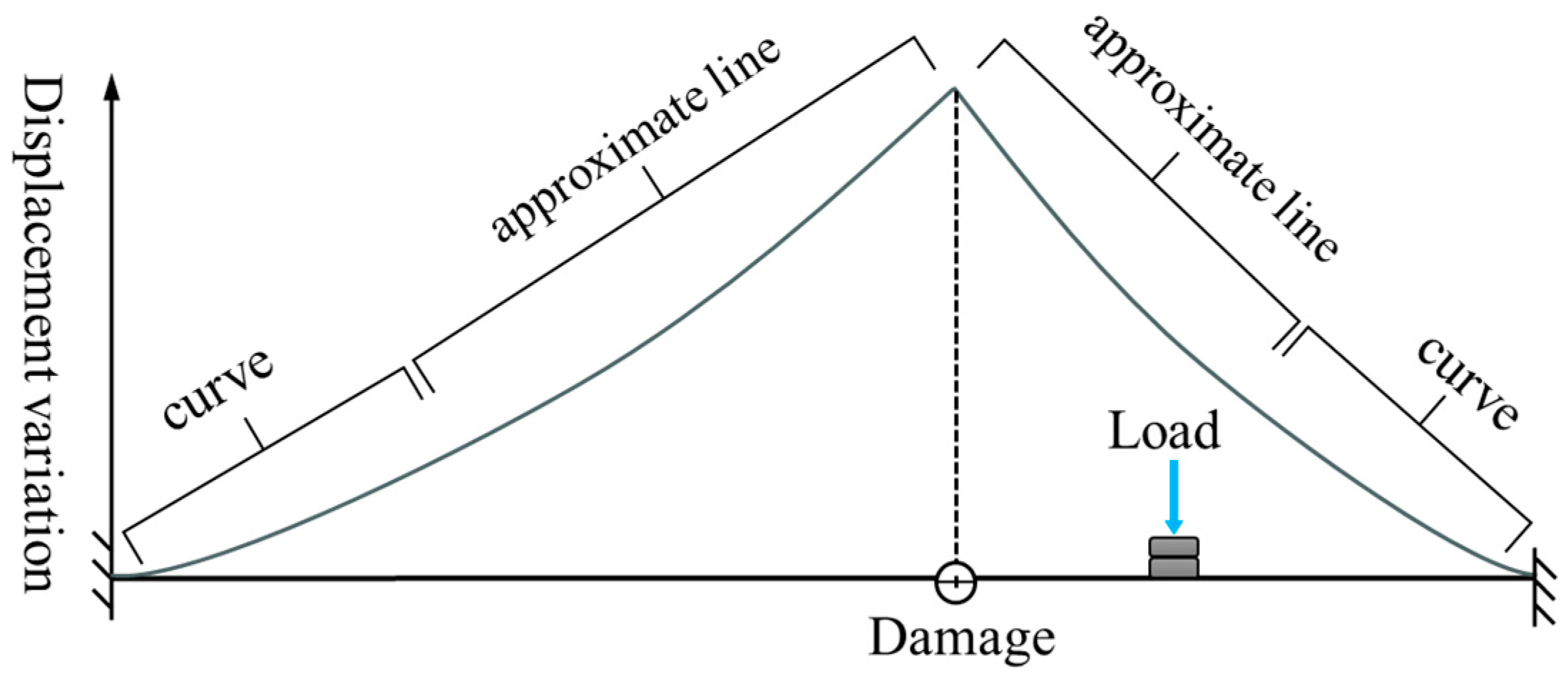
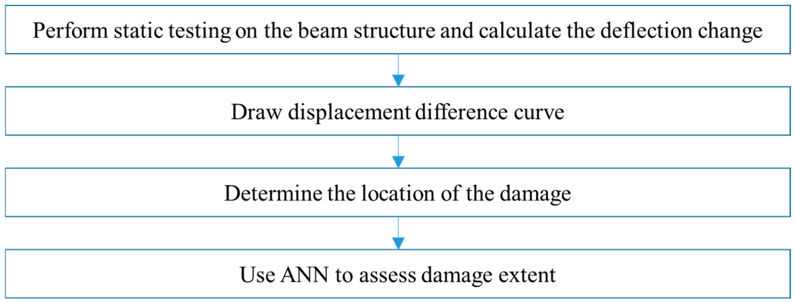
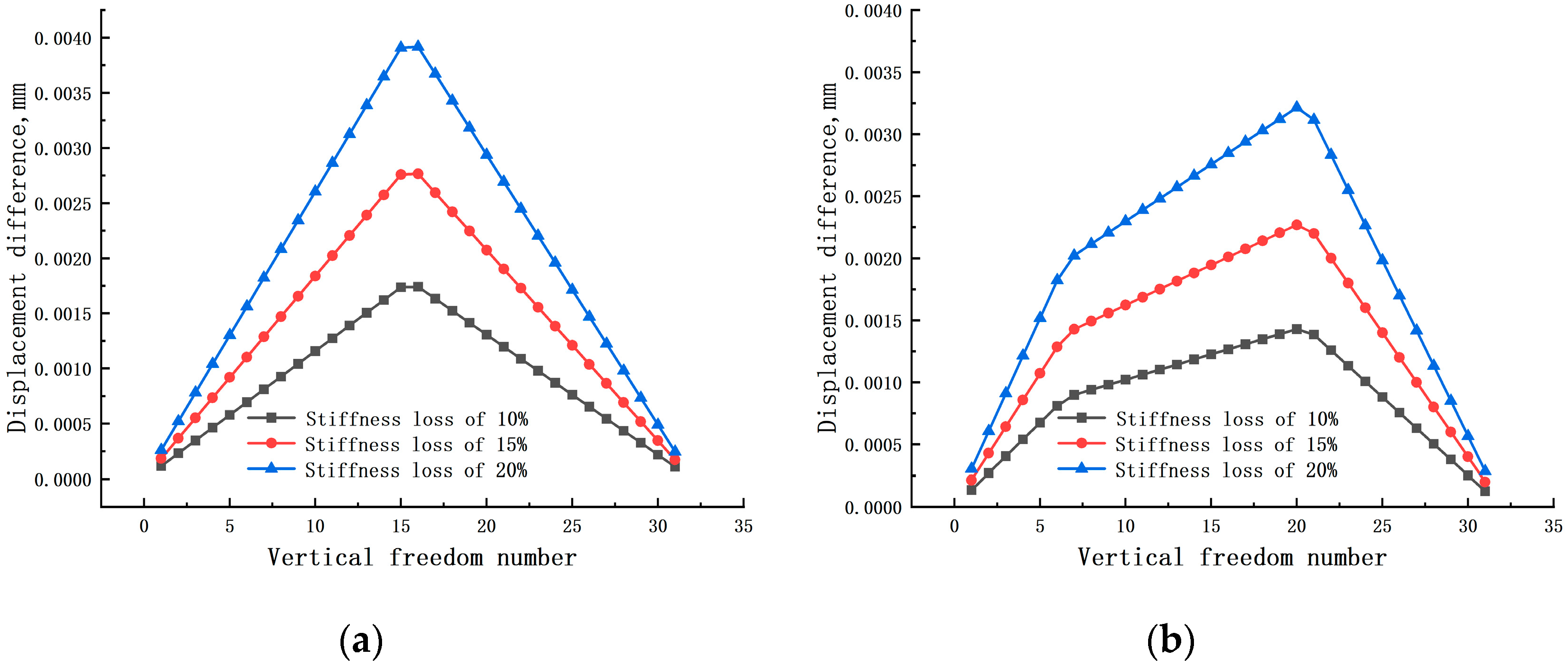
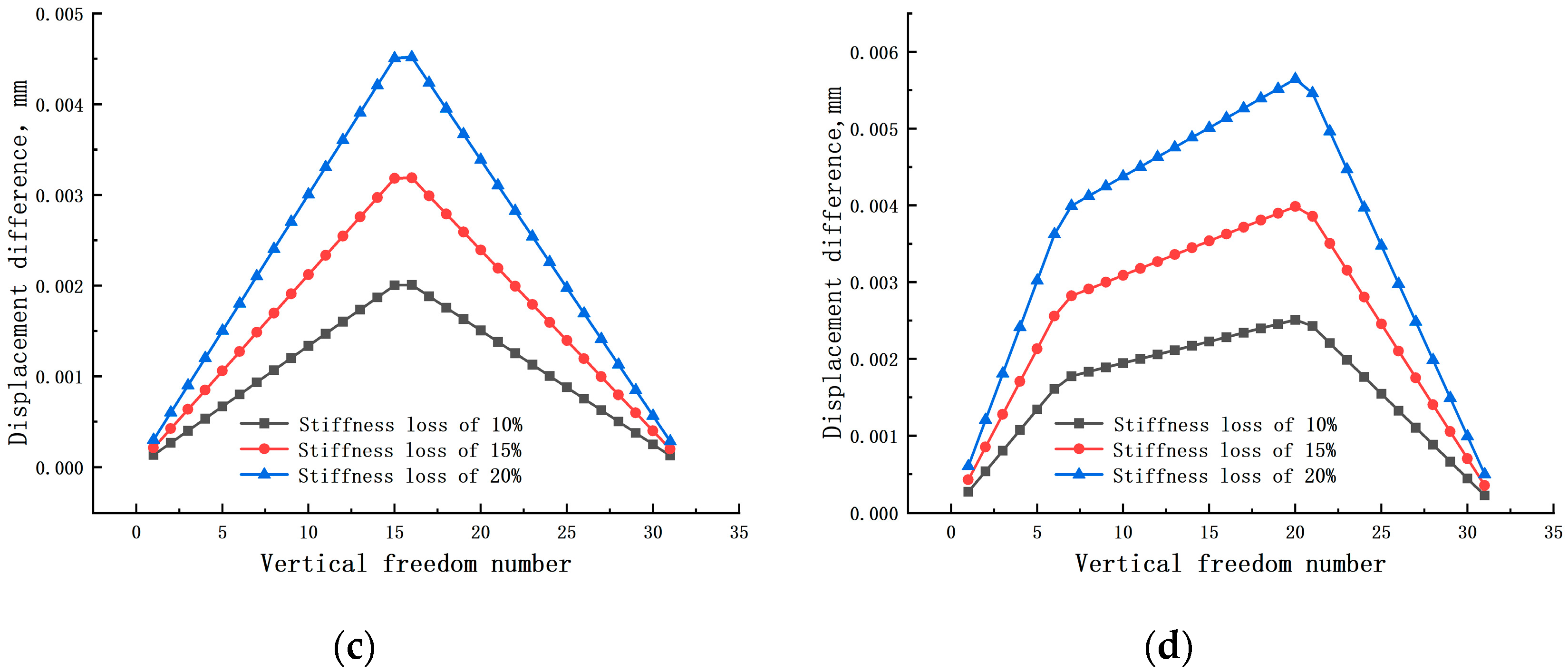
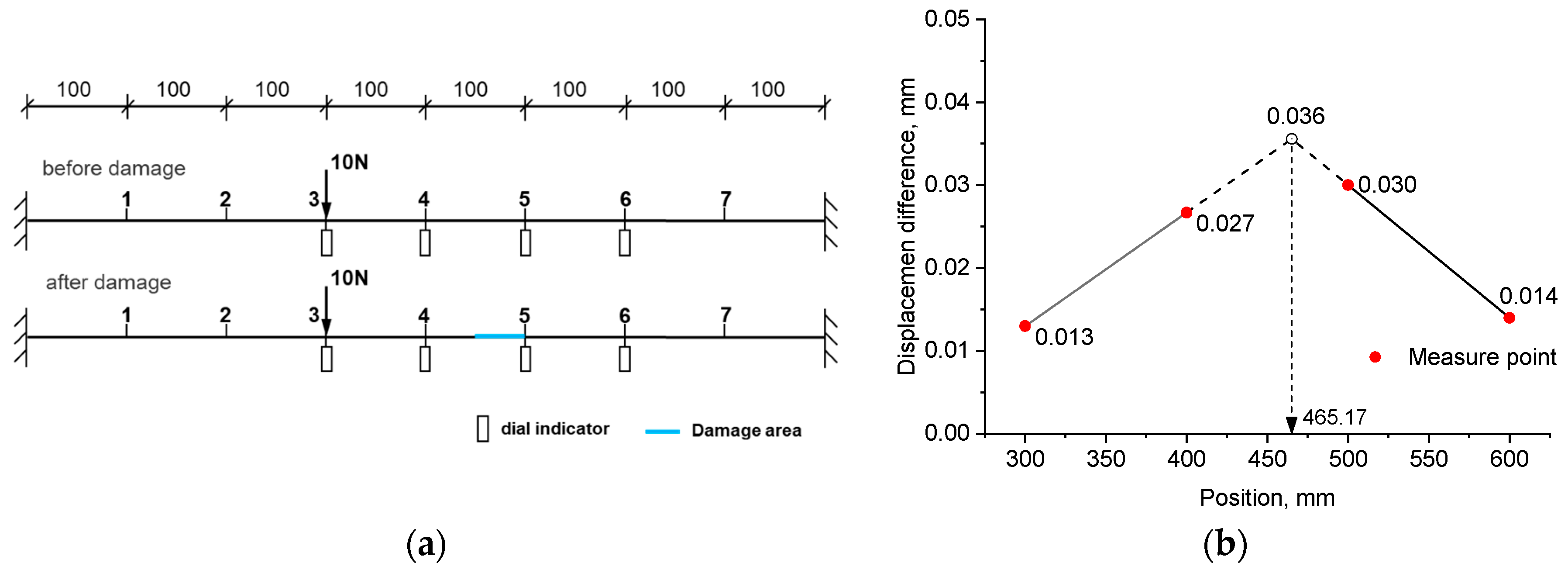
  • When there is a single damage in the beam structure, the displacement difference curve will exhibit one inflection point. When multiple damages exist in the beam structure, the displacement difference curve will show multiple inflection points;
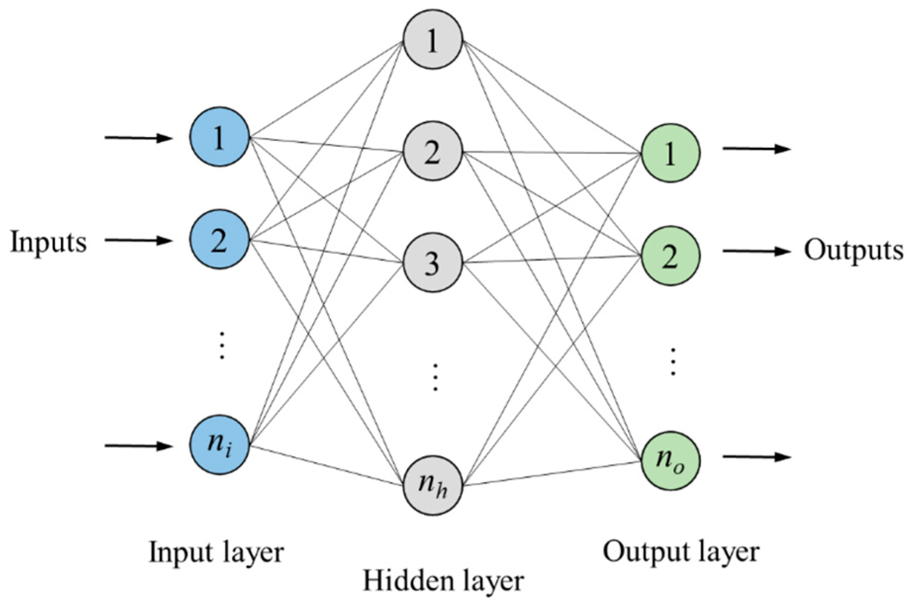
  • On the basis of the damage location already being determined, further adoption of a trained ANN can more accurately calculate the severity of structural damage. Pre-locating the damage can significantly reduce the number of samples required for training the ANN model, as well as decrease the number of neurons in the ANN model.
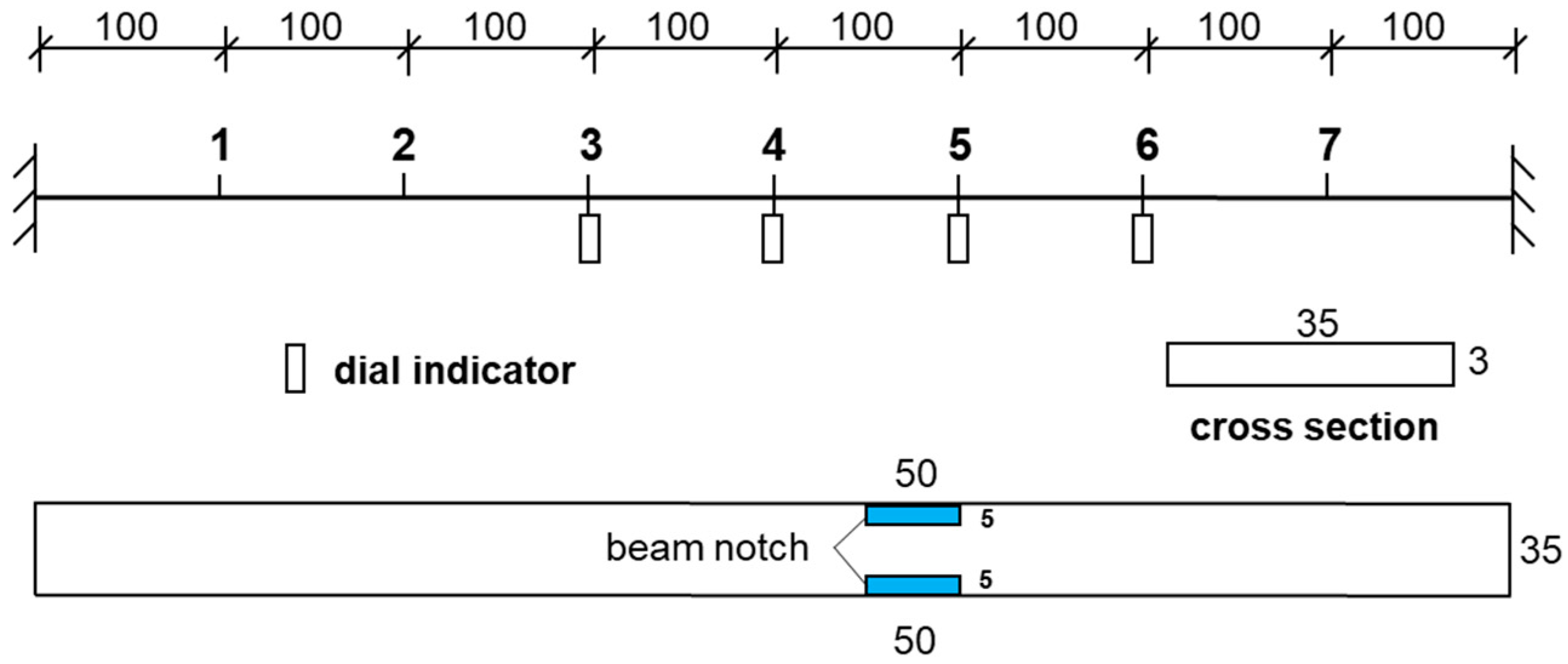
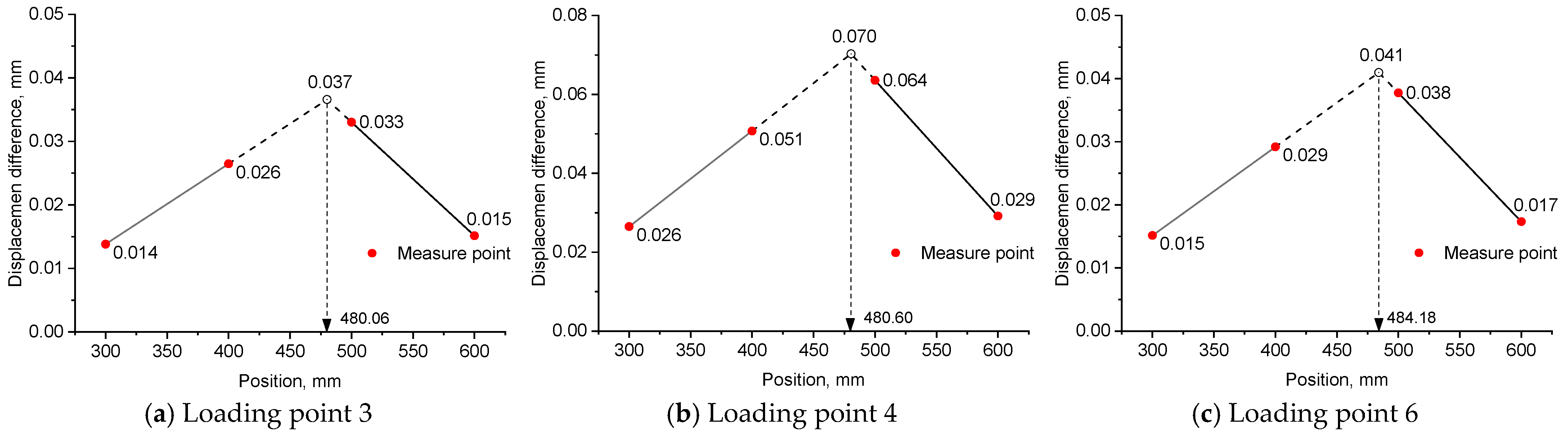
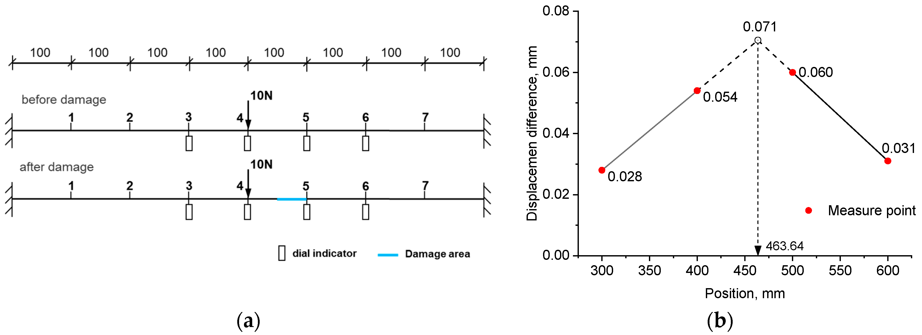
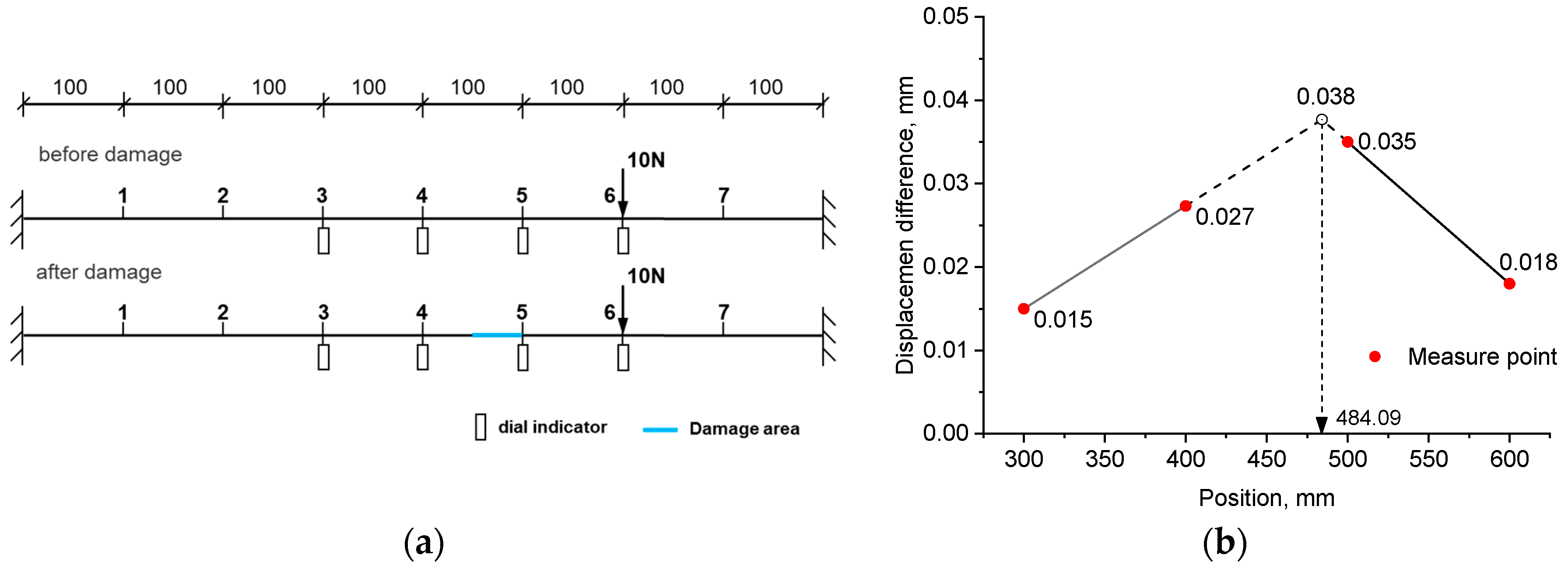
  • For experiment example 1, under three loading modes, the identified damage positions from the left support were 465.17 mm, 463.64 mm, and 484.09 mm, respectively. They all fell within the range of the actual damage location, which was between 450 mm and 500 mm. The trained neural network accurately calculated the severity of the damage, with errors of 3.40%, 1.78%, and 6.16% for the three loading modes, respectively.
  • For experiment example 2, the actual damage was simulated by cutting a portion of the steel beam at a distance of 1175 mm from the left support. The identified damage location was 1158.3 mm away from the left support. The distance error between the identified damage location and the actual damage location was 1.4%. The calculated severity of the damage (42.67%) was also very close to the actual degree of damage (41.51%), with an error of 2.8%.
  • The implementation of this two-phase damage detection approach is highly convenient, as it facilitates precise identification of damage in beam structures with minimal displacement data, offering a straightforward and immensely practical means for defect detection in such structures.

Author Contributions

Conceptualization, X.H., X.P., Q.Y. and F.Q.; methodology, X.P.; investigation, Q.Y., X.P. and F.Q.; writing—original draft preparation, X.H., X.P., Q.Y. and F.Q.; project administration, X.P. and B.X.; funding acquisition, B.X. All authors have read and agreed to the published version of the manuscript.

Funding

This work is supported by the Key Projects of Yongjiang Science and Technology Innovation 2035 in Ningbo (No. 2024Z090) and the Major Science and Technology Project of Ningbo High-Tech Zone in 2023 (No. 2023CX050001).

Institutional Review Board Statement

Not applicable.

Informed Consent Statement

Not applicable.

Data Availability Statement

The original contributions presented in this study are included in the article. Further inquiries can be directed to the corresponding authors.

Conflicts of Interest

Xi Peng and Bin Xu were employed by the company Ningbo Roaby Technology Industrial Group Co., Ltd. The remaining authors declare that the research was conducted in the absence of any commercial or financial relationships that could be construed as a potential conflict of interest.

Glossary

SSBSingle slotted beam system
DSBDouble slotted beam system
DCDeflection change
BPBackpropagation
ANNArtificial neural network
IFInternal force
diff.Difference
MWMegawatts
CFDComputational fluid dynamics
DFBIDynamic fluid body interaction
VOFVolume of fluid
LCLoad condition
Δ d Displacement before and after damage
K u Stiffness matrix before damage
d u Displacement before damage
K d Stiffness matrix after damage
d d Displacement after damage
f Load vector
Δ K The change in the stiffness matrix caused by damage
α i The damage extent of the i -th element
K i The i -th elemental stiffness matrix
d d , j The j - th   coefficient   of   the   vector   d d
ξ j Characteristic displacement vector
η j The characteristic force vector
K e The stiffness matrix of a single beam element
n i Input layer’s neuron count
n o Output layer’s neuron count
n h Hidden layer’s neuron count
E Young’s modulus
ρ Density
I Moment of inertia
A Cross-sectional area

References

  1. He, W.Y.; Ren, W.X.; Zhu, S. Baseline-free damage localization method for statically determinate beam structures using dual-type response induced by quasi-static moving load. J. Sound Vib. 2017, 400, 58–70. [Google Scholar] [CrossRef]
  2. He, W.Y.; Ren, W.X.; Zhu, S. Damage detection of beam structures using quasi-static moving load induced displacement response. Eng. Struct. 2017, 145, 70–82. [Google Scholar] [CrossRef]
  3. Greco, A.; Pluchino, A.; Cannizzaro, F. Closed-form solution based genetic algorithm software: Application to multiple cracks detection on beam structures by static tests. Appl. Soft Comput. 2018, 64, 35–48. [Google Scholar] [CrossRef]
  4. Oudah, F.; El-Hacha, R. Damage and deformation assessment of earthquake-resistant RC slotted beam-column connections using digital image correlation technique. Eng. Struct. 2020, 215, 110442. [Google Scholar] [CrossRef]
  5. Ma, Q.; Solís, M.; Galvín, P. Wavelet analysis of static deflections for multiple damage identification in beams. Mech. Syst. Signal Process. 2021, 147, 107103. [Google Scholar] [CrossRef]
  6. Jahangir, H.; Hasani, H.; Esfahani, M.R. Wavelet-based damage localization and severity estimation of experimental RC beams subjected to gradual static bending tests. In Structures; Elsevier: Amsterdam, The Netherlands, 2021; Volume 34, pp. 3055–3069. [Google Scholar]
  7. Wu, N.; Wang, Q. Experimental studies on damage detection of beam structures with wavelet transform. Int. J. Eng. Sci. 2011, 49, 253–261. [Google Scholar] [CrossRef]
  8. Pooya, S.M.H.; Massumi, A. A novel damage detection method in beam-like structures based on the relation between modal kinetic energy and modal strain energy and using only damaged structure data. J. Sound Vib. 2022, 530, 116943. [Google Scholar] [CrossRef]
  9. Yang, Q.; Liu, J.; Sun, B. Damage localization for beam structure by moving load. Adv. Mech. Eng. 2017, 9, 91–105. [Google Scholar] [CrossRef]
  10. Omid, Y.; Ali, R.I.; Mehdi, D. Static data based damage localization of beam-column structures considering axial load. Mech. Adv. Mater. Struct. 2020, 27, 1433–1450. [Google Scholar]
  11. Shi, Q.; Hu, K.; Wang, L.; Wang, X. Uncertain identification method of structural damage for beam-like structures based on strain modes with noises. Appl. Math. Comput. 2021, 390, 125682. [Google Scholar] [CrossRef]
  12. Peng, X.; Yang, Q.W. Damage detection in beam-like structures using static shear energy redistribution. Front. Struct. Civ. Eng. 2023, 16, 1552–1564. [Google Scholar] [CrossRef]
  13. Hashemi, M.S.; Izadifard, R.A.; Yazdanpanah, O. Experimental static data-based damage localization of beam-like structures considering axial load. Inverse Probl. Sci. Eng. 2021, 29, 1729–1745. [Google Scholar] [CrossRef]
  14. Ma, Q.Y.; Mario, S. Damage localization and quantification in beams from slope discontinuities in static deflections. Smart Struct. Syst. 2018, 22, 291–302. [Google Scholar]
  15. Le, T.N.; Nguyen, A.; Thambiratnam, P.D.; Chan, T.H.T.; Khuc, T. Locating and Quantifying Damage in Beam-like Structures Using Modal Flexibility-based Deflection Changes. Int. J. Struct. Stab. Dyn. 2020, 20, 20. [Google Scholar] [CrossRef]
  16. Zhang, S.; Liu, Y. Damage Detection in Beam Bridges Using Quasi-static Displacement Influence Lines. Appl. Sci. 2019, 9, 1805. [Google Scholar] [CrossRef]
  17. Yang, J.; Li, P.; Yang, Y.; Xu, D. An improved EMD method for modal identification and a combined static-dynamic method for damage detection. J. Sound Vib. 2018, 420, 242–260. [Google Scholar] [CrossRef]
  18. Chen, Y.; Liu, R.; Zheng, S. Identification and Diagnosis of Bridge Structural Damage Based on Static Test Data. Iran. J. Sci. Technol. Trans. Civ. Eng. 2024, 48, 2981–2996. [Google Scholar] [CrossRef]
  19. Wang, Z.F.; Huang, B.; Tee, K.F.; Zhang, W.D. A Novel Stochastic Approach for Static Damage Identification of Beam Structures Using Homotopy Analysis Algorithm. Sensors 2021, 21, 2366. [Google Scholar] [CrossRef]
  20. Shen, J.B.; Li, Z.K.; Luo, S.; Wang, W. A Structural Damage Identification Method Based on Arrangement of the Static Force Residual Vector. Front. Mater. 2022, 9, 918069. [Google Scholar] [CrossRef]
  21. Alkhabbaz, A.; Hamza, H.; Daabo, M.A.; Yang, H.S.; Yoon, M.; Koprulu, A.; Lee, Y.H. The aero-hydrodynamic interference impact on the NREL 5-MW floating wind turbine experiencing surge motion. Ocean Eng. 2024, 295, 116970. [Google Scholar] [CrossRef]
  22. Yang, S.H.; Alkhabbaz, A.; Tongphong, W.; Lee, H.Y. Cross-comparison analysis of environmental load components in extreme conditions for pontoon-connected semi-submersible FOWT using CFD and potential-based tools. Ocean Eng. 2024, 304, 117248. [Google Scholar] [CrossRef]
  23. Daabo, M.A.; Alkhabbaz, A.; Ibrahim, S.S.; Hamzah, H.; Hassan, H.; Basem, A.; Easa, H.; Pavlovic, S. Thirteen vital factors for micro-scale radial turbine vane’s design of geo-solar-powered Brayton cycle applications. Energy Convers. Manag. 2024, 315, 118774. [Google Scholar] [CrossRef]
  24. Yang, Q.W.; Du, S.G.; Liang, C.F.; Yang, L.J. A Universal Model-Independent Algorithm for Structural Damage Localization. CMES Comput. Model. Eng. Sci. 2014, 100, 223–248. [Google Scholar]
  25. Le, N.T.; Thambiratnam, D.P.; Nguyen, A.; Chan, T.H.T. A new method for locating and quantifying damage in beams from static deflection changes. Eng. Struct. 2019, 180, 779–792. [Google Scholar] [CrossRef]
Figure 1. The two-node Bernoulli-Euler plane beam element with four DOFs [24].
Coatings 15 00289 g001
Figure 2. The internal force (IF) distribution in the structure under the action of the characteristic force [24].
Coatings 15 00289 g002
Figure 3. The displacement variation (DV) due to damage for the fixed-fixed beam under a point load [24].
Coatings 15 00289 g003
Figure 4. The ANN model.
Coatings 15 00289 g004
Figure 5. The flowchart of the two-stage damage detection method.
Coatings 15 00289 g005
Figure 6. (a) Load condition 1; (b) Load condition 2. (The number in the circle represents the element number of this simply supported beam).
Coatings 15 00289 g006
Figure 7. Displacement differences before and after damage. (a) Element 16 is damaged in LC1; (b) Elements 7 and 21 are damaged in LC1; (c) Element 16 is damaged in LC2; (d) Elements 7 and 21 are damaged in LC2. (unit: mm).
Coatings 15 00289 g007aCoatings 15 00289 g007b
Figure 8. Static test of beam structure.
Coatings 15 00289 g008
Figure 9. Geometric parameters, measurement locations, and size of the notch (unit: mm).
Coatings 15 00289 g009
Figure 10. Numerical simulation results of the tested steel beam.
Coatings 15 00289 g010
Figure 11. (a) Gravity load acts on node 6; (b) Displacement difference before and after damage obtained from the experiment (unit: mm).
Coatings 15 00289 g011
Figure 12. (a) Gravity load acts on node 4; (b) Displacement difference before and after damage obtained from the experiment (unit: mm).
Coatings 15 00289 g012
Figure 13. (a) Gravity load acts on node 3; (b) Displacement difference before and after damage obtained from the experiment (unit: mm).
Coatings 15 00289 g013
Figure 14. (a) Static test of beam structure; (b) Cross-sectional diagram (c) Displacement difference before and after damage (unit: μ m ).
Coatings 15 00289 g014
Table 1. The mean and standard deviation of the displacement difference corresponding to loading point 3 (unit: mm).
Measure point3456
Mean value0.0130.0270.0300.014
Standard deviation0.00200.00120.00200.0010
Table 2. The mean and standard deviation of the displacement difference corresponding to loading point 4 (unit: mm).
Measure point3456
Mean value0.0280.0540.0600.031
Standard deviation0.00200.00260.00530.0026
Table 3. The mean and standard deviation of the displacement difference corresponding to loading point 6 (unit: mm).
Measure point3456
Mean value0.0150.0270.0350.018
Standard deviation0.00440.00060.00260.0095
Disclaimer/Publisher’s Note: The statements, opinions and data contained in all publications are solely those of the individual author(s) and contributor(s) and not of MDPI and/or the editor(s). MDPI and/or the editor(s) disclaim responsibility for any injury to people or property resulting from any ideas, methods, instructions or products referred to in the content.

