Article

Enhancing Strength and Ductility in the Nugget Zone of Friction Stir Welded X80 Pipeline Steel via Applying Cooling Medium

1
School of Materials Science and Engineering, Jiangsu University of Science and Technology, Zhenjiang 212003, China
2
State Key Laboratory of Rolling and Automation, Northeastern University, No. 3 Wenhua Road, Shenyang 110819, China
3
School of Materials Science and Engineering, Tsinghua University, Beijing 100084, China
4
State Key Laboratory of Metastable Materials Science and Technology, Yanshan University, Qinhuangdao 066004, China
*
Authors to whom correspondence should be addressed.
Coatings 2025, 15(3), 260; https://doi.org/10.3390/coatings15030260
Submission received: 7 February 2025 / Revised: 19 February 2025 / Accepted: 20 February 2025 / Published: 21 February 2025
(This article belongs to the Special Issue Research in Laser Welding and Surface Treatment Technology)

Abstract

:
Fusion welding easily causes microstructural coarsening and tempering softening in the heat-affected zone (HAZ) of high-strength pipeline steel joints, which considerably deteriorates the strength and toughness. Here, X80 pipeline steel was subjected to friction stir welding (FSW), and external cooling was used to tailor the microstructure to optimize the strength–ductility combination of the nugget zone (NZ). Coarse granular bainite (GB) appeared at air cooling, whereas a fine ferrite/martensite microstructure was achieved at solid CO2 cooling. The highest ratio of high-angle boundaries was obtained at solid CO2 cooling because the variants were evenly distributed within the four close-packed (CP) groups. The low yield strength (YS) of 595 MPa was obtained in the NZ under air cooling, whereas a high YS of 755 MPa was achieved in the NZ under solid CO2 cooling due to dislocation strengthening and fine-grain strengthening. Furthermore, an ultra-high tensile strength of 910 MPa and utilizable elongation of 15% were obtained in the NZ under solid CO2 cooling, which was attributed to the fine effective grains and ferrite/martensite microstructure facilitating a ductile fracture.

1. Introduction

Pipeline transportation has the advantages of convenience, high efficiency, reliability, and economy, and it is considered to be one of the best ways to transport oil and gas [1,2,3]. With the increasing demand for energy, pipeline steel is developing towards high-strength and ultra-high-strength steel, including X80, X100, and X120 pipeline steel [4,5]. At present, X80 pipeline steel has been widely used in the field of energy transportation, while X100 and X120 pipeline steel are still in the test stage [6,7]. Welding is an important joining process for long-distance pipelines. However, traditional fusion welding has some disadvantages, such as machining grooves, welding wire and flux, preheating before welding, etc., resulting in low production efficiency and high manufacturing costs [8,9,10]. Furthermore, high heat input easily leads to serious microstructure inhomogeneity and complex residual stress in the heat-affected zone (HAZ), resulting in lower strength and ductility of the joint. Therefore, a new welding method is urgently needed to reduce production costs and achieve high-quality welding.
Friction stir welding (FSW), as a highly reliable solid-state joining technology, has the advantages of severe plastic deformation, low peak temperature, low processing time, and high-quality joints [11,12]. Compared with traditional fusion welding, FSW does not require filler metal/flux and has high welding efficiency, which is conducive to reducing production costs. At the same time, high-quality welded joints reduce maintenance and replacement costs caused by welding defects and increase the market competitiveness of products. Therefore, FSW has great potential for applications in many fields, including railway, pipeline, aerospace, renewable energy, and aerospace [13,14]. Generally, high heat input is required in FSW X80 pipeline steel to ensure excellent nugget zone (NZ) formation [15,16,17]. However, high heat input easily leads to the formation of coarse granular bainite (GB) and lath bainite (LB), resulting in a decrease in mechanical properties. Therefore, some studies have tried to carry out FSW X80 pipeline steel under external cooling [18,19]. Xie et al. [18] performed FSW on X80 pipeline steel under various cooling mediums and reported that the microstructure of the NZ was gradually refined as the temperature of the cooling medium decreased. However, the strength and ductility of the NZ were not studied. Xue et al. [19] noted the NZ of FSW X80 pipeline steel by applying water cooling containing ferrite and bainite, resulting in a significant enhancement of strength–ductility combination. Up to now, many studies have focused on the effect of cooling medium on the microstructure evolution and mechanical properties of the NZ, but the influence of external cooling on the microstructure characteristics and its effect on deformation and fracture behavior was not investigated in detail.
In this study, FSW technology was utilized to join X80 pipeline steel, and an external cooling medium was performed. The influence of different cooling mediums on the change of the microstructure, deformation, and fracture behaviors of the NZ was systematically studied. The objective was to clarify the mechanism of the cooling medium effect on mechanical properties based on understanding the relationship between the cooling medium and microstructure characteristics.

2. Experimental Procedure

Six mm-thick X80 pipeline steel plates with the chemical composition listed in Table 1 were used as the base metal (BM). During FSW (Beijing FSW Technology Co. Ltd, Beijing, China), the rotation rate and welding speed were 400 rpm and 100 mm/min, respectively. Moreover, during FSW, the mixture of small amounts of water + solid CO2 (solid CO2) cooling medium was used to improve the microstructure and mechanical properties. A W-25Re alloy tool consisting of a shoulder 15 mm in diameter and a pin 9 mm in diameter with a 5 mm length was utilized. Figure 1a shows the FSW process, and the peak temperatures of the NZs were measured using a telemetry measurement system (MegaStir Technologies, Spanish Fork, UT, USA) placed near the shoulder.
Figure 1b shows the sampling position of the microstructural specimen and tensile samples. The microstructure features of the NZs were systematically observed using a scanning electron microscope (SEM, Zeiss Gemini 300, Oberkochen, Germany) equipped with a back-scattered diffractometer (EBSD, Oxford Instruments Symmetry, Oxford, UK) and transmission electron microscope (TEM, FEI Tecnai G2-F20, Thermo Fisher Scientific, Waltham, MA, USA). The SEM specimens were ground and corroded with 4 % nital. Electro-polishing was applied to prepare the EBSD and TEM samples using 87.5% C2H6O and 12.5% HClO4 solution. The size of the tensile specimen is shown in Figure 1c, and all tensile tests were performed at room temperature. The observed position of the tensile fracture is shown in Figure 1d.

3. Results and Discussion

3.1. Microstructure Evolution

Figure 2 reveals the SEM and TEM images of the NZs at various cooling mediums. It can be found that the prior austenite grains (PAGs) were significantly refined under the external cooling medium. At air cooling, a coarse GB with blocky M-A constituents was detected in the NZ, while fine martensite with ferrite dispersion distribution was obtained in the NZ when the solid CO2 cooling was utilized. Previous studies indicated that bainitic ferrite preferentially nucleates at PAG boundaries with low C content, and C-rich austenite is formed with the growth of bainitic ferrite because C atoms in the bainitic ferrite are excluded [4,20]. During subsequent cooling, part of that austenite is transformed into martensite, i.e., the M-A constituent is formed. Therefore, at air cooling, the blocky M-A constituents were formed along the PAG boundaries and within GB. By contrast, a low peak temperature was obtained in the NZ under solid CO2 cooling, inhibiting PAG growth. Furthermore, a fast post-weld cooling rate is conducive to the occurrence of martensite transformation. As a result, fine martensite was discovered in the NZ under solid CO2 cooling. Furthermore, some ferrite was identified in the NZ because some ferrites did not austenize during FSW. Similarly, ferrite/martensite microstructures were observed in the NZ of FSW X80 owing to the application of liquid CO2.
Figure 3 reveals the EBSD results and corresponding statistics of the NZs at various cooling mediums. The white, black, and red lines indicate low-, medium-, and high-angle grain boundaries (LAGBs, 2° ≤ θ <15°; MAGBs, 15° ≤ θ <45°; HAGBs, 45° ≤ θ), respectively. Previous studies indicated that the MAGBs and HAGBs corresponded to PAG boundaries and packet boundaries for bainite and martensite, respectively [18,21]. The fraction of LAGBs, MAGBs, and HAGBs in the NZ under air cooling and solid CO2 cooling were 63.7%, 6.5%, and 28.8% and 57.6%, 6.4%, and 36.5%, respectively. After the application of the cooling medium, the fraction of MAGBs and HAGBs increased obviously. Surprisingly, the fraction of LAGBs in the NZ under air cooling was higher than that in the NZ under solid CO2 cooling. Generally, the fast post-weld cooling rate inhibits the recovery of dislocations and substructures, promoting the formation of LAGBs. In this case, the LAGB length per unit area was measured to elucidate this phenomenon, which was 0.55 and 0.74 μm−1 in the NZ at air and solid CO2 cooling, respectively. This indicated an increase in the number of LAGBs in the NZ after applying the applied cooling.
To further analyze the influence of different cooling mediums on grain boundary characteristics, the crystallographic characteristics of the NZ under different cooling mediums were studied in detail, as shown in Figure 4. Different colors in the IPF represent different grain orientations and variation distributions. Figure 4c,d reveals that the number of variants generated was lower at air cooling, while a large number of variants generated at solid CO2 cooling. This is attributed to the fact that austenite is softer at high temperatures, and the transformation strain can be eliminated by plastic deformation of austenite during the transformation, i.e., plastic accommodation, leading to variant selection [22,23]. However, the high cooling rate inhibits carbon diffusion, leading to the hardening of austenite due to the solid solution strengthening of carbon. As a result, the transformation strain generated in the phase transformation is difficult to eliminate with the plastic deformation of austenite. In this case, different adjacent variants are generated in the PAG to eliminate the transformation strain, i.e., self-accommodation, resulting in more transformation strain being consumed during transformation. Thus, self-accommodation was dominant at solid CO2 cooling, inhibiting variant selection and, ultimately, multiple variant generation.
Figure 5 shows the Bain groups and close-packed (CP) groups in a single PAG under various cooling mediums, which were reconstructed by ARPGE software. Generally, there are 24 orientation relationships between the austenite and bainite, that is, 24 variants, which can be divided into three Bain groups or four CP groups. At air cooling, the fraction of variants in the four CP groups was unevenly distributed and mainly belonged to the same Bain group, indicating that the predominant Bain group formed and thus led to a decrease in HAGBs. By contrast, the fraction of variants in the four CP groups was evenly distributed at solid CO2 cooling, and three Bain groups were alternately distributed in the PAG, suggesting that the predominant CP group generated and resulted in an increase of HAGBs.
In fact, the generation of Bain or CP groups is closely related to variant selection. To clarify the effect of the cooling medium on variant selection, the variant fraction in the PAGs under air and solid CO2 cooling is calculated and shown in Figure 6. At air cooling, fewer variants were generated, and some variants account for a large proportion, indicating that serious variant selection occurred. At solid CO2 cooling, the variant variety increased, and the proportion of each variant did not change significantly, suggesting that the variant selection was inhibited. Wang et al. [21] pointed out that a high cooling rate can effectively inhibit variant selection in the fusion welding of low-carbon steel, facilitating the formation of the CP group. However, the low cooling rate promoted variant selection, resulting in the generation of Bain groups. Furthermore, our previous study found that the strong deformation of FSW created severe variant selection in the NZ of bainitic steel, forming the Bain group [4]. Therefore, under air cooling, the low cooling rate and intense deformation together promoted the variant selection, while the high cooling rate is the dominant factor in inhibiting the variant selection under solid CO2 cooling.
To further clarify the relationship between the variants and the Bain or CP groups, local crystallographic orientations in the PAG were observed, as shown in Figure 7. The HAGBs, MAGBs, and LAGBs were characterized by red, block, and white lines, respectively. The three Bain groups and four CP groups are represented by three colors (yellow, red, and blue), four colors (yellow, blue, red, green), and six colors (brown, blue, pink, ultramarine, dark green, and yellow), respectively. It can be found that a coarse bainitic block and fine martensitic block were detected in the CP group under air and solid CO2 cooling, respectively. Previous studies indicated that the Bain and CP groups correspond to the block and packet, respectively [24]. This result was consistent with the high fraction of HAGB generation in the NZ under solid CO2 cooling. Furthermore, Figure 7c,f reveals that the low-misorientation variant pairs (V13/V16 and V15/V18) were generated within blocks at various cooling conditions. Generally, the high cooling rate can effectively inhibit the generation of low-misorientation variant pairs. However, the ratio of low-misorientation variant pairs in the blocks under solid CO2 cooling increased significantly compared to that of air cooling. This may be attributed to the amounts of dislocations introduced during FSW because of strong plastic deformation, and the fast post-welding cooling rate inhibited dislocation recovery, facilitating the formation of low-misorientation variant pairs in the blocks.
Figure 8 reveals the geometrically necessary dislocation (GND) maps, recrystallization maps, and corresponding statistics of the NZs under various cooling mediums. It can be found that the GND distribution in the NZs was uniform, regardless of FSW conditions, and the GND density in the NZ under solid CO2 cooling increased dramatically. In the NZ under air cooling and solid CO2 cooling, the average GND densities were 6.7 × 10¹⁴ and 11.6 × 10¹⁴ m−2, respectively. This may be attributed to the high post-weld cooling rate inhibiting the recovery and annihilation of dislocations. Figure 8d,e reveals that, at air cooling, the NZ predominantly consisted of substructured and a few deformed grains, while the number of deformed grains increased markedly in the NZ under solid CO2 cooling. Clearly, the variation of the deformed grain ratio was consistent with the GND map analysis.

3.2. Mechanical Properties

Figure 9 provides the tensile results of the NZ under various cooling mediums. At air cooling, the NZ presented a poor yield strength (YS) of 595 MPa, low ultimate tensile strength (UTS) of 680 MPa, and high total elongation (TE) of 19.2%. However, extremely high strength and utilizable elongation were obtained in the NZ under solid CO2 cooling, and the YS, UTS, and TE were 755 MPa, 910 MPa, and 15%, respectively. In addition, the product of strength and elongation (PSE) of the NZ at air cooling and solid CO2 cooling was 13 GPa% and 13.7 GPa%, respectively. Clearly, the combination of the strength and ductility of the NZ under solid CO2 cooling was improved, indicating that FSW X80 pipeline steel under external cooling can effectively enhance the tensile properties of the NZ.
Obviously, the yield strength of the NZ increased significantly after the application of a cooling medium. Typically, the yield strength ( σ y ) consists of the contributions of ferrite lattice friction stress ( σ 0 , 54 MPa), grain boundaries ( σ g ), solid solution ( σ s s ), dislocation ( σ d ), and second phase ( σ s ) and can be constructed as seen in the following equation [25,26,27,28].
σ y = σ 0 + σ g + σ s s + σ d + σ s
For grain refinement strengthening, the grain size and strengthening effect follow the Hall–Petch relationship below [25,26].
σ g = k y d
Here, k y donates the strengthening coefficient, 504 MPa μm1/2; d donates grain size, μm. Generally, grain boundaries with misorientation angles ≥15° are defined as effective grain boundaries. Thus, the average grain sizes of the NZ under air cooling and solid CO2 cooling were measured to be 9.3 and 5.1 μm, respectively, and the grain refinement strengthening increment of the NZ under air cooling and solid CO2 cooling were calculated to be 165 and 223 MPa, respectively.
Regarding solid solution strengthening, the relationship between chemical composition and solid solution strength can be illustrated as follows [25,27].
σ s s = 32 Mn + 83 Si + 678 P + 31 Cu + 11 Mo 31 Gr + 5544   ( N ss + C ss )
Here, the concentrations are in weight percent, and the Nss and Css are nitrogen and carbon in a solid solution, respectively. The value of (Nss+Css) is 0.7% in pipeline steel [27]. In this work, the alloy composition content in the NZ did not change due to the solid-phase joining characteristics of FSW. Thus, the solution-strengthening increments in the NZ under air cooling and solid CO2 cooling were 113 MPa and 113 MPa, respectively.
Regarding dislocation strengthening, the following classical model can be used for calculation [25,26].
σ d = M α b G ρ
Here, M donates the average Taylor factor; α donates the constant, 0.2; b donates the Burgers vector, 2.5 × 10⁻⁴ μm; G donates the shear modulus, 64000 MPa; and ρ donatesthe dislocation density. In this work, the average Taylor factor of the NZ at air cooling and solid CO2 cooling was 2.8 and 2.9, respectively. Therefore, the dislocation-strengthening increment in the NZ under air cooling and solid CO2 cooling was 204 and 358 MPa, respectively.
In addition, the second-phase strengthening resulting from M-A constituent obeys the Ashby–Orowan relation, as shown in the following equation [25,28].
σ s = 10.8 f D In D 6.125 × 10 4
Here, f donates the volume fraction of the second-phase particle, and D donates the average second-phase particle diameter (μm). At air cooling, the D and f of the M-A constituent were 1.25 μm and 13.5%, respectively. Therefore, the second-phase strengthening increment in the NZ under air cooling was 24 MPa. By contrast, the microstructure of the NZ under solid CO2 cooling was mainly composed of martensite, without the M-A constituent’s contribution to yield strength.
Based on the above analysis, the contribution of various strengthening mechanisms to yield strength is summarized in Figure 10, and the yield strength measured by experiments is also added in the figure. It can be found that the experimentally measured values were basically consistent with those calculated by theory, and the significant increase in the yield strength of the NZ at solid CO2 cooling was mainly due to dislocation strengthening and grain-refinement strengthening. Apparently, the yield strength in the NZ of FSW X80 pipeline steel can be effectively improved by applying a cooling medium.
To further reveal the outstanding tensile properties of the NZ under solid CO2 cooling, the strain hardening rate (SHR) vs. the true strain curves were calculated, as shown in Figure 11. At the initial stage of plastic deformation, the SHR value of the NZ under solid CO2 cooling was higher than that in the NZ under cooling rate, but it decreased rapidly with an increase in the strain. As a result, the SHR value of the NZ under solid CO2 cooling was lower than that under air cooling at the later stage of plastic deformation. Previous studies indicated that high dislocation density within martensite promotes strong dislocation entanglement to occur in the early stages of plastic deformation, resulting in high SHR [29,30]. However, as the strain increases, the high density of the lattice defects inside the martensite (vacancies and dislocations) can hinder the slip of dislocations introduced by deformation [31,32]. As a result, the SHR value decreases because the amount of dislocation multiplication introduced by deformation is less than the amount consumed by dynamic recovery. By contrast, ferrite or bainite ferrite can promote dislocation multiplication in the later stage of plastic deformation relative to martensite microstructure due to its low dislocation density, obtaining continuously high SHR values [29,33]. Furthermore, grain refinement can reduce the average free path of dislocations because grain boundaries can act as barriers to the dislocation slip [34]. Therefore, high strength and available elongation were achieved in the NZ under solid CO2 cooling due to grain refinement and ferrite/martensite microstructure, while only high elongation was obtained in the NZ under air cooling owing to coarse GB.
After necking, the stress state of the necking area changes from uniaxial to triaxial, which promotes the formation of voids due to the enhancement of stress concentration. As the strain increases, the voids undergo growth and coalescence, eventually leading to fracture. To elucidate the relationship between microstructure characteristics and fracture behavior, the tensile fracture characteristics in the NZ under different cooling mediums were observed, as shown in Figure 12. At air cooling, the voids were mainly generated near the M-A constituent, and the crack propagation path was straight. Furthermore, a small number of large and deep dimples were observed on the fractural surface, indicating that the crack needs to consume less energy during propagation. By contrast, the initiation of the voids was mainly at the interface between martensite and ferrite under solid CO2 cooling, and the crack propagation path was tortuous. In addition, a large number of small and deep dimples were dispersed on the fracture surface, suggesting that more energy was consumed during the propagation of cracks.
Previous studies reported that grain size, M-A constituents, and phase composition have obvious effects on fracture behavior [34,35,36]. First, decreasing the grain size can increase the brittle fracture stress because grain refinement reduces the strain gradient between the grain interior and grain boundary during tensile deformation. Furthermore, the high density of the effective grain boundaries can effectively hinder and deflect crack propagation, which makes crack propagation require more energy consumption. Second, the M-A constituent, as a hard and brittle second-phase particle, easily causes stress concentration, and a coarse M-A constituent can reduce the critical stress for void generation, promoting the initiation of voids near the M-A constituent. Third, the ferrite/martensite microstructure has two positive effects on improving fracture behavior compared with single-phase ferrite or martensite. One is that ferrite has a higher deformability because it is limited by the surrounding martensite during deformation. The other is that the deformation capacity of martensite is also improved because of the co-deformation of ferrite and martensite, which effectively alleviates the stress concentration at the ferrite/martensite interface. Consequently, the plastic deformation ability of the NZ was markedly enhanced due to grain refinement and the generation of the ferrite/martensitic microstructure.
In the field of pipeline steel joining, FSW has a broad application prospect because of its advantages of severe plastic deformation, low peak temperature, low processing time, and high-quality joints. However, the effects of FSW parameters including rotation rate, welding speed, and cooling medium on the microstructure evolution and their effects on the mechanical properties are still insufficient. Thus, it is necessary to further optimize FSW parameters and clarify the strength–plasticity mechanism of welded joints in the future. In addition, for the pipeline in service, ensuring weld safety is even more important. The methods to verify the quality of the weld mainly include appearance inspection, non-destructive testing, and sealing inspection (such as air tightness test, kerosene leakage test). In the future, the integrated application of these inspection means can ensure that the quality of the weld meets the relevant standards and requirements.

4. Conclusions

(1)
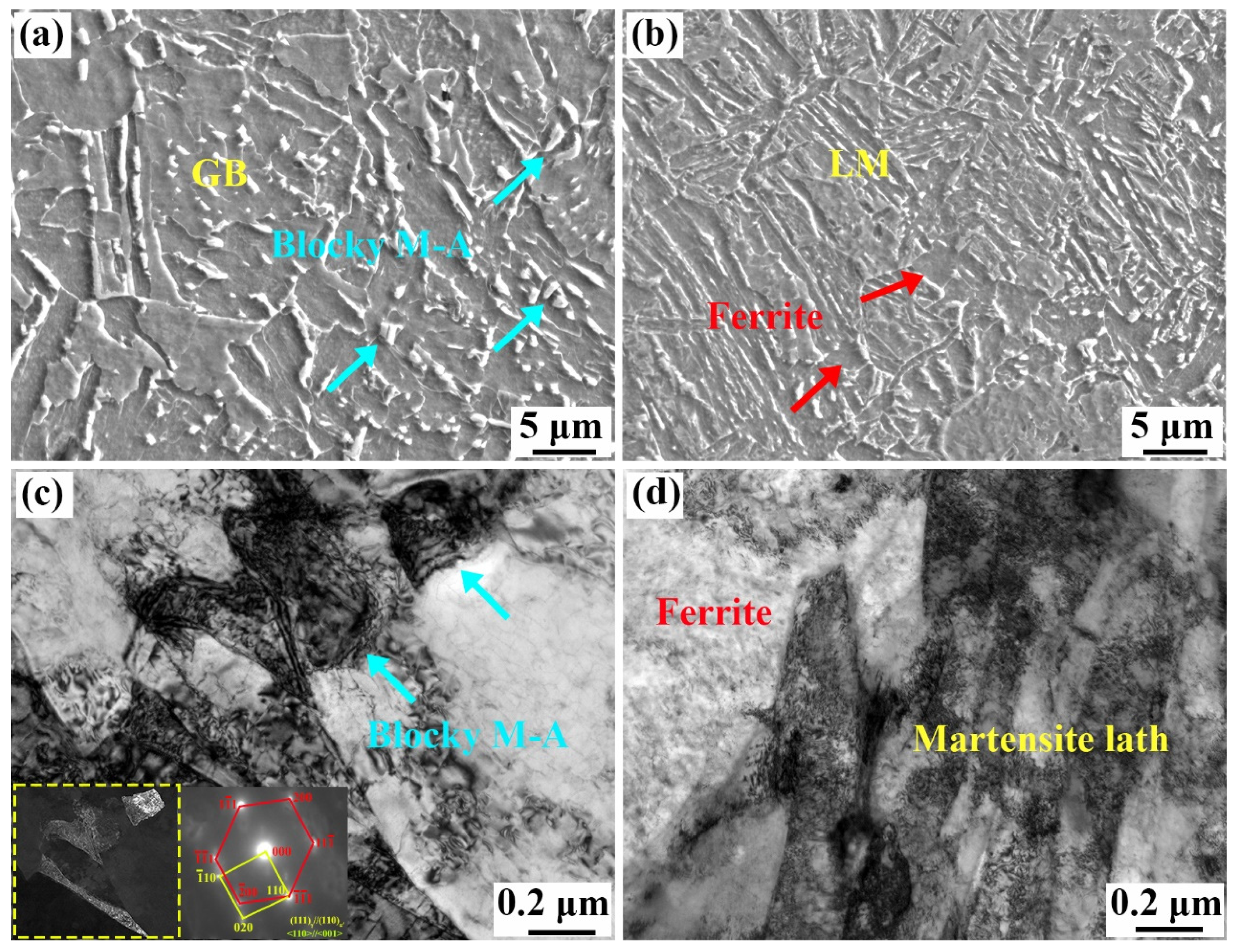
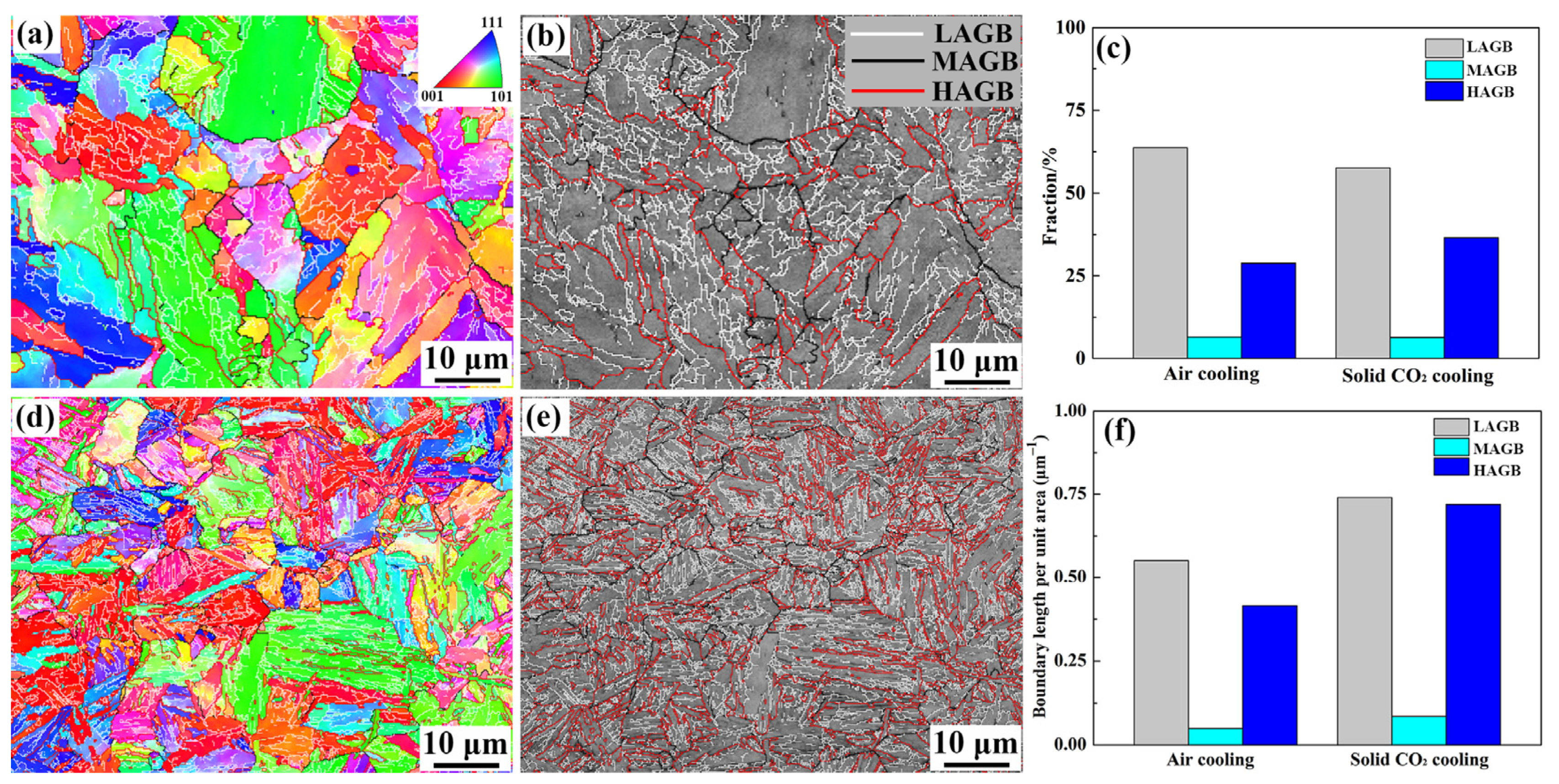
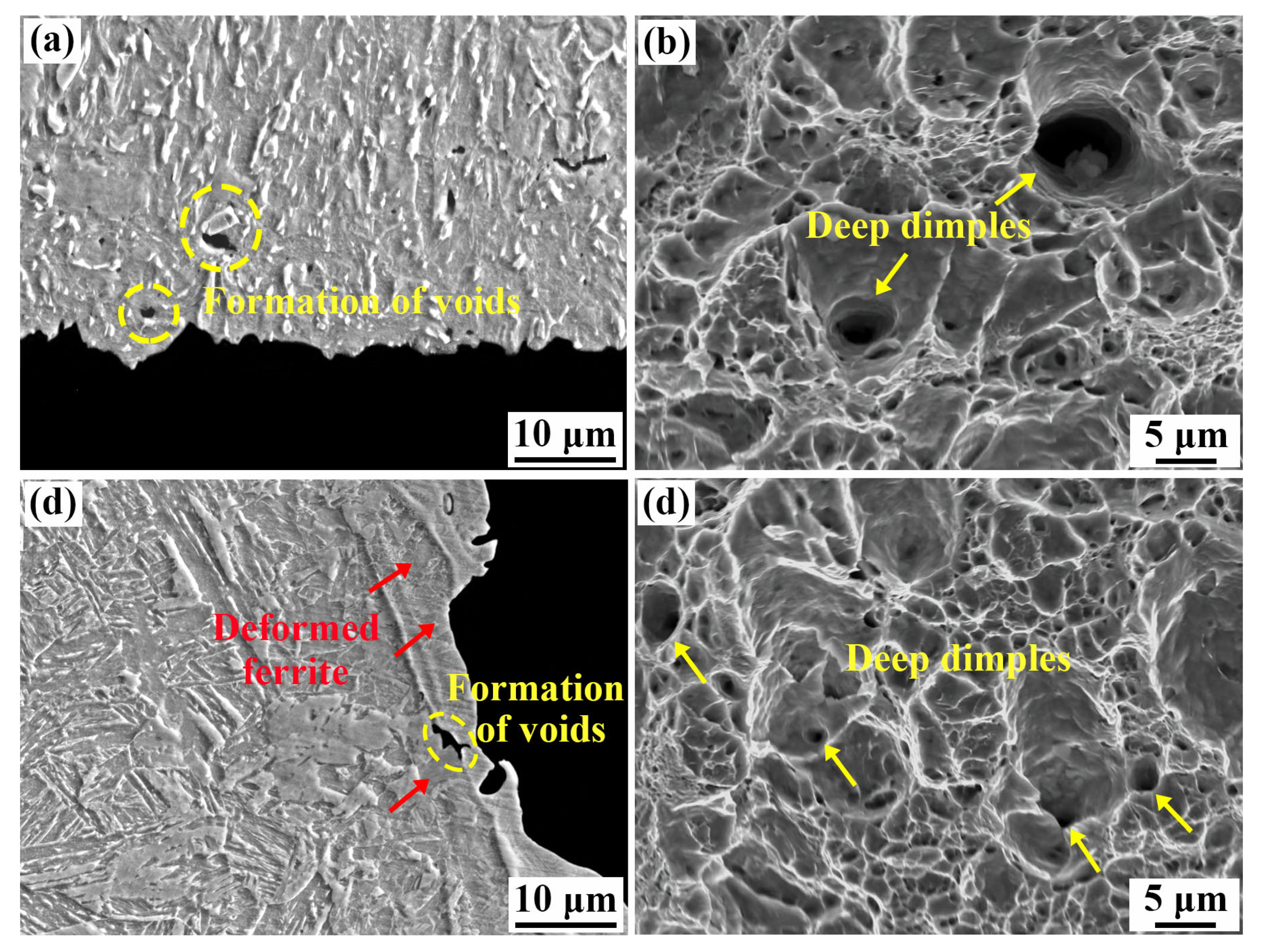
Coarse GB was obtained in the NZ under air cooling, whereas a fine ferrite/martensite microstructure was identified in the NZ under solid CO2 cooling. The fraction of MAGBs and HAGBs obviously increased, while that of LAGBs decreased under solid CO2 cooling.
(2)
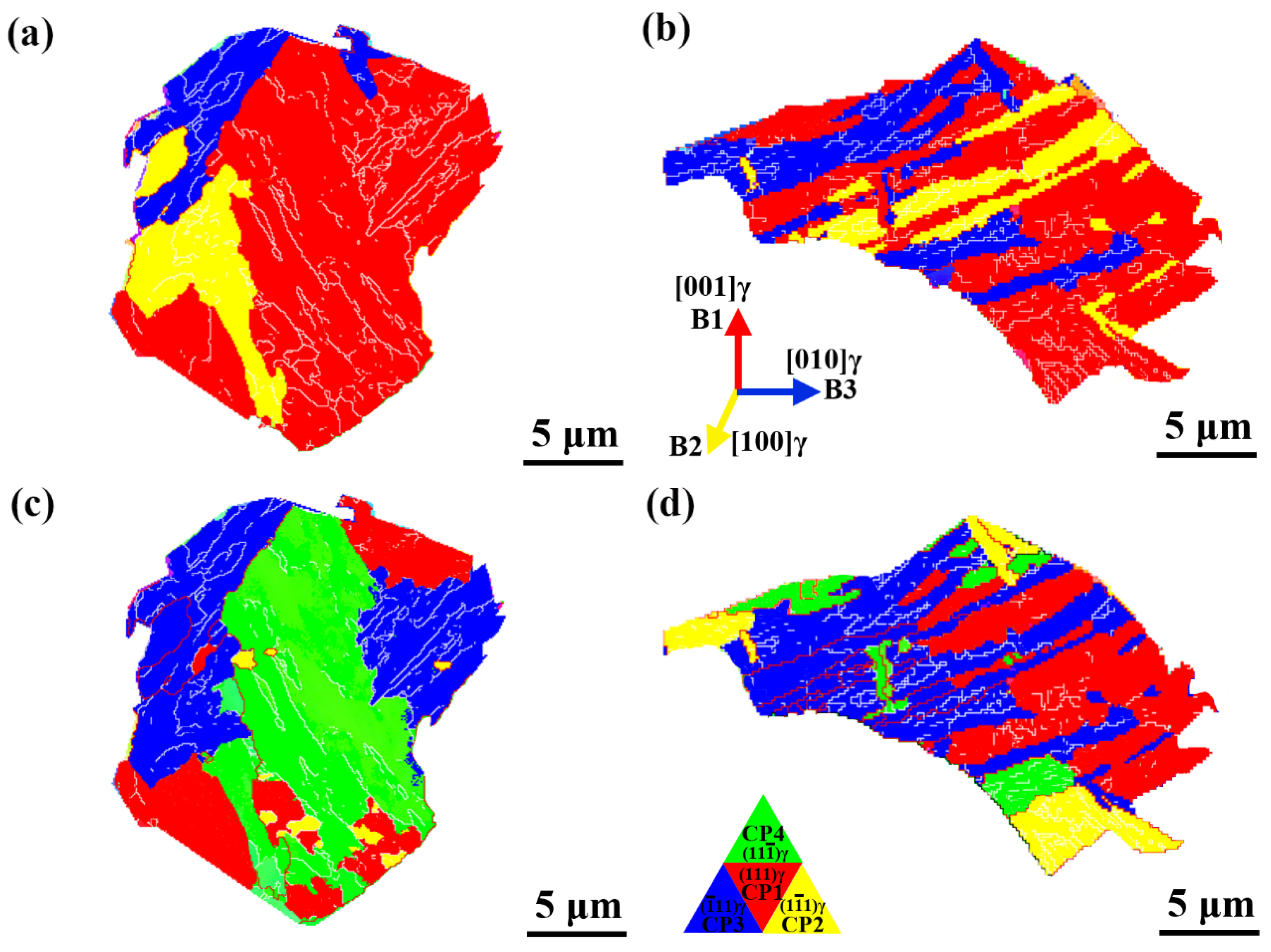
At air cooling, the variants were mainly distributed in the Bain1 group, causing the highest ratio of low-misorientation variant pairs, while a high ratio of high-misorientation variant pairs was obtained in the NZ under solid CO2 cooling.
(3)
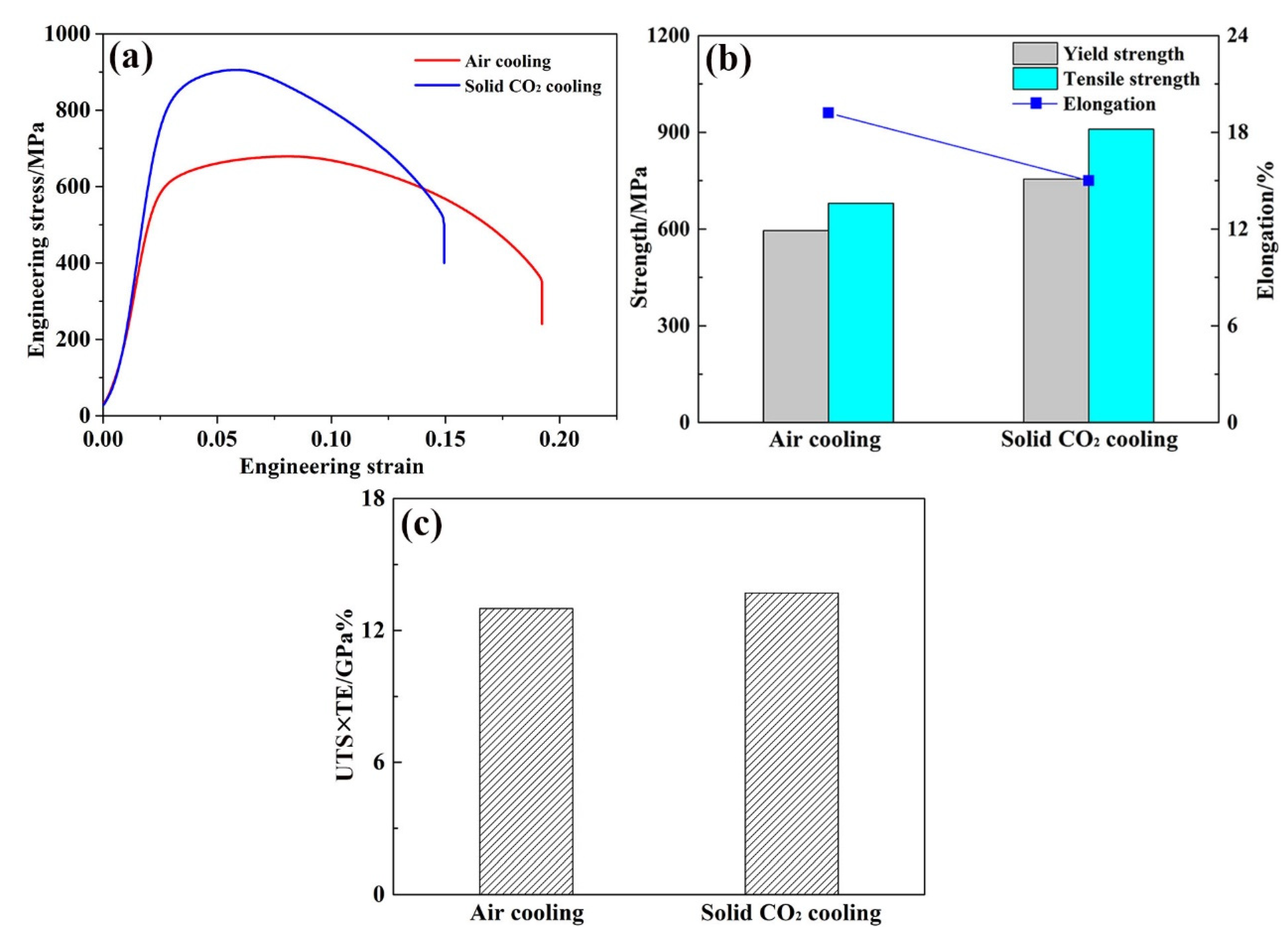
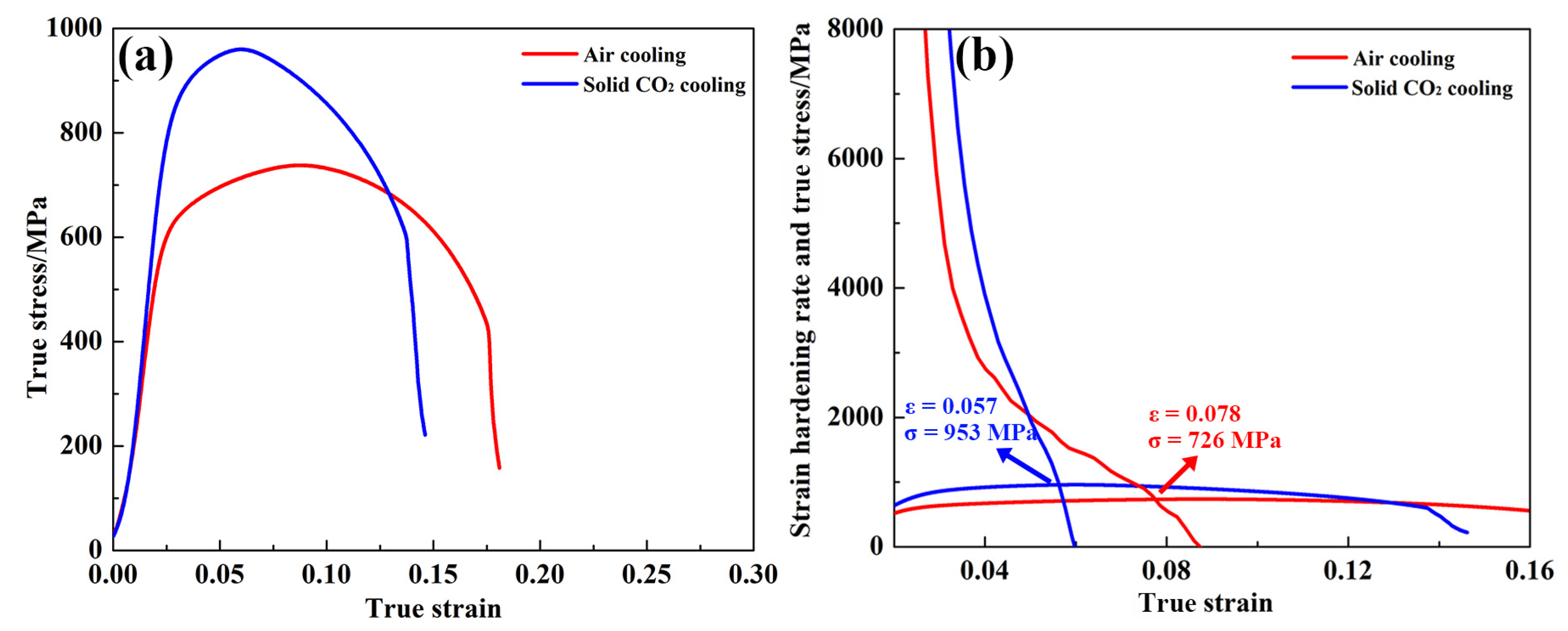
At solid CO2 cooling, the excellent YS (755 MPa) of the NZ was obtained due to the dislocation strengthening and refinement grain strengthening. Furthermore, the NZ presented an ultra-high tensile strength (910 MPa) and utilizable elongation (15%) depending on consistently high work hardening rates caused by the generation of a fine ferrite/martensite microstructure.

Author Contributions

Methodology, R.D. and G.X.; validation, R.D., G.X. and X.Q.; original draft preparation, R.D., Z.W. and S.C.; writing–review and editing, R.D. and Y.D.; Funding acquisition, G.X. and S.C. All authors have read and agreed to the published version of the manuscript.

Funding

National Nature Science Foundation of China (Nos. 52274378 and 51774085; National Nature Science Foundation of China (No. 52275339).

Institutional Review Board Statement

Not applicable.

Informed Consent Statement

Not applicable.

Data Availability Statement

Data are contained within the article.

Conflicts of Interest

The authors declare no conflicts of interest.

References

  1. Velázquez, J.C.; Hernández-Huerta, J.J.; Diaz-Cruz, M.; Hernández-Sánchez, E.; Cervantes-Tobón, A.; Capula-Colindres, S.I.; Cabrera-Sierra, R. Study on the influence of non-Metallic inclusions on the pitting corrosion of API 5L X60 steel. Coatings 2023, 13, 1040. [Google Scholar] [CrossRef]
  2. Yao, C.; Ming, H.L.; Chen, J.; Wang, J.Q.; Han, E.H. Effect of cold deformation on the hydrogen permeation behavior of X65 pipeline steel. Coatings 2023, 13, 280. [Google Scholar] [CrossRef]
  3. Cho, Y.H.; Lee, J.; Choo, W.Y.; Kang, J.; Han, H.N. Effect of separation on the fracture surface of pipeline steels with ferrite-bainite dual phases during drop weight tear test. Met. Mater. Int. 2022, 28, 1340–1348. [Google Scholar] [CrossRef]
  4. Duan, R.H.; Xie, G.M.; Luo, Z.A.; Xue, P.; Wang, C.; Misra, R.D.K.; Wang, G.D. Microstructure, crystallography, and toughness in nugget zone of friction stir welded high-strength pipeline steel. Mater. Sci. Eng. A 2020, 791, 139620. [Google Scholar] [CrossRef]
  5. Oi, X.N.; Huan, P.C.; Wang, X.N.; Shen, X.J.; Liu, Z.G.; Di, H.S. Effect of microstructure homogeneity on the impact fracture mechanism of X100 pipeline steel lase-MAG hybrid welds with an alternating magnetic field. Mater. Sci. Eng. A 2022, 851, 143656. [Google Scholar]
  6. Cheng, X.D.; Huang, R.K.; Xu, L.Y.; Ma, C.; Zhu, X.J. Parametric study on the trench designing for X80 buried steel pipeline crossing oblique-reverse fault. Soil Dyn. Earthq. Eng. 2021, 150, 106824. [Google Scholar] [CrossRef]
  7. Jia, Y.Z.; Wang, J.Q.; Han, E.H.; Ke, W. Stress corrosion cracking of X80 pipeline steel in Near-Neutral Ph environment under constant load tests with and without preload. J. Mater. Sci. Technol. 2011, 27, 1039–1046. [Google Scholar] [CrossRef]
  8. Midawi, A.R.H.; Santos, E.B.F.; Huda, N.; Sinha, A.K.; Lazor, R.; Gerlich, A.P. Microstructures and mechanical properties in two X80 weld metals produced using similar heat input. J. Mater. Process. Tech. 2015, 226, 272–279. [Google Scholar] [CrossRef]
  9. Jorge, L.J.; Candido, V.S.; Silva, A.C.R.; Garcia, F.C.; Pereira, A.C.; Luz, F.S.; Monteiro, S.N. Mechanical properties and microstructure of SMAW welded and thermically treated HSLA-80 steel. J. Mater. Res. Technol. 2018, 7, 598–605. [Google Scholar] [CrossRef]
  10. Midawi, A.R.H.; Simha, C.H.M.; Gerlich, A.P. Assessment of yield strength mismatch in X80 pipeline steel welds using instrumented indentation. Int. J. Press. Vessel. Pip. 2018, 168, 258–268. [Google Scholar] [CrossRef]
  11. Li, K.; Liu, X.M.; Zhao, Y. Research status and prospect of friction stir processing technology. Coatings 2019, 9, 129. [Google Scholar] [CrossRef]
  12. Ehiasarian, A.; Purandare, Y.; Sugumaran, A.; Hovsepian, P.; Hatto, P.; Backer, J.D. Improving the quality of friction stir welds in aluminium alloys. Coatings 2021, 11, 539. [Google Scholar] [CrossRef]
  13. Meng, X.C.; Huang, Y.X.; Cao, J.; Cao, J.J.; Santos, J.F. Recent progress on control strategies for inherent issues in friction. Prog. Mater. Sci. 2021, 115, 100706. [Google Scholar] [CrossRef]
  14. Magalhães, V.M.; Leitão, C.; Rodrigues, D.M. Friction stir welding industrialisation and research status. Sci. Technol. Weld. Join. 2018, 23, 400–409. [Google Scholar] [CrossRef]
  15. Aydin, H.; Nelson, T.W. Microstructure and mechanical properties of hard zone in friction stir welded X80 pipeline steel relative to different heat input. Mater. Sci. Eng. A 2013, 586, 313–322. [Google Scholar] [CrossRef]
  16. Santos, T.F.A.; Hermenegildo, T.F.C.; Afonso, C.R.M.; Marinho, R.R.; Paes, M.T.P.; Ramirez, A.J. Fracture toughness of ISO 3183 X80M (API 5L X80) steel friction stir welds. Eng. Fract. Mech. 2010, 77, 2937–2945. [Google Scholar] [CrossRef]
  17. Avila, J.A.; Rodriguez, J.; Mei, P.R.; Ramirez, A.J. Microstructure and fracture toughness of multipass friction stir welded joints of API-5L-X80 steel plates. Mater. Sci. Eng. A 2016, 673, 257–265. [Google Scholar] [CrossRef]
  18. Xie, G.M.; Duan, R.H.; Xue, P.; Ma, Z.Y.; Liu, H.L.; Luo, Z.A. Microstructure and mechanical properties of X80 pipeline steel joints by friction stir welding under various cooling conditions. Acta. Metall. Sin. (Engl. Lett.). 2020, 33, 88–102. [Google Scholar] [CrossRef]
  19. Xue, P.; Komizo, Y.C.; Ma, Z.Y. Microstructure and mechanical properties of friction stir welded X80 pipeline steel joint under additional cooling. In Proceedings of the 1st International Joint Symposium on Joining and Welding, Osaka, Japan, 6–8 November 2017. [Google Scholar]
  20. Yang, X.C.; Di, X.J.; Liu, X.G.; Wang, D.P.; Li, C.N. Effects of heat input on microstructure and fracture toughness of simulated coarse-grained heat affected zone for HSLA steels. Mater. Charact. 2019, 155, 109818. [Google Scholar] [CrossRef]
  21. Wang, X.L.; Wang, Z.Q.; Dong, L.L.; Shang, C.J.; Ma, X.P.; Subramanian, S.V. New insights into the mechanism of cooling rate on the impact toughness of coarse grained heat affected zone from the aspect of variant selection. Mater. Sci. Eng. A 2017, 704, 448–458. [Google Scholar] [CrossRef]
  22. Sun, M.Y.; Wang, X.L.; Wang, Z.Q.; Wang, X.M.; Li, X.C.; Yan, L.; Misra, R.D.K. The critical impact of intercritical deformation on variant pairing of bainite/martensite in dual-phase steels. Mater. Sci. Eng. A 2020, 771, 138668. [Google Scholar] [CrossRef]
  23. Takayama, T.; Miyamoto, G.; Furuhara, T. Effects of transformation temperature on variant pairing of bainitic ferrite in low carbon steel. Acta Mater. 2012, 33, 2387–2396. [Google Scholar] [CrossRef]
  24. Wang, X.L.; Wang, Z.Q.; Ma, X.P.; Subramanian, S.V.; Xie, Z.J.; Shang, C.J.; Li, X.C. Analysis of impact toughness scatter in simulated coarse-grained HAZ of E550 grade offshore engineering steel from the aspect of crystallographic structure. Mater. Charact. 2018, 140, 312–319. [Google Scholar] [CrossRef]
  25. Altuna, M.A.; Iza-Mendia, A.; Gutiérrez, I. Precipitation of Nb in ferrite after austenite conditioning. Part II: Strengthening contribution in high-strength low-alloy (HSLA) steels. Metall. Mater. Trans. A 2012, 43, 4571–4586. [Google Scholar] [CrossRef]
  26. Charleux, M.; Poole, W.J.; Militzer, M.; Deschamps, A. Precipitation behavior and its effect on strengthening of an HSLA-Nb/Ti steel. Metall. Mater. Trans. A 2001, 32, 1635–1647. [Google Scholar] [CrossRef]
  27. Gutiérrez, I.; Altuna, M.A. Work-hardening of ferrite and microstructure-based modeling of its mechanical behaviour under tension. Acta Mater. 2008, 56, 4682–4690. [Google Scholar] [CrossRef]
  28. Kostryzhev, A.G.; Shahrani, A.A.; Zhu, C.; Cairney, J.M.; Ringer, S.P.; Killmore, C.R.; Pereloma, E.V. Effect of niobium clustering and precipitation on strength of an NbTi-microalloyed ferritic steel. Mater. Sci. Eng. A 2014, 607, 226–235. [Google Scholar] [CrossRef]
  29. Xue, P.; Xiao, B.L.; Wang, W.G.; Zhang, Q.; Wang, D.; Wang, Q.Z.; Ma, Z.Y. Achieving ultrafine dual-phase structure with superior mechanical property in friction stir processed plain low carbon steel. Mater. Sci. Eng. A 2013, 575, 30–34. [Google Scholar] [CrossRef]
  30. Wang, Y.Q.; Duan, R.H.; Hu, J.; Luo, Z.A.; Ma, Z.Y.; Xie, G.M. Improvement in toughness and ductility of friction stir welded medium-Mn steel joint via post-welding annealing. J. Mater. Process. Tech. 2022, 306, 117621. [Google Scholar] [CrossRef]
  31. Ji, R.Y.; Zhang, H.C.; Chen, L.Y.; Cheng, L.W.; Luo, H.J.; Mao, J. Improving the strength and maintaining good ductility of as-forged Ti6Al4V alloy by regulating the microstructural defects. Mater. Sci. Eng. A 2024, 911, 146913. [Google Scholar] [CrossRef]
  32. Wang, H.S.; Zhang, Y.X.; Yuan, G.; Kang, J.; Wang, Y.; Misra, R.D.K.; Wang, G.D. Significance of cold rolling reduction on Lüders band formation and mechanical behavior in cold-rolled intercritically annealed medium-Mn steel. Mater. Sci. Eng. A 2018, 737, 176–181. [Google Scholar] [CrossRef]
  33. Duan, R.H.; Wang, Y.Q.; Luo, Z.A.; Wang, G.D.; Xie, G.M. Achievement of excellent strength and plasticity in the nugget zone of friction stir welded bainitic steel and its deformation behavior. J. Mater. Res. Technol. 2022, 20, 3381–3390. [Google Scholar] [CrossRef]
  34. Bouaziz, O.; Allain, S.; Scott, C. Effect of grain and twin boundaries on the hardening mechanisms of twinning-induced plasticity steels. Scr. Mater. 2008, 58, 484–487. [Google Scholar] [CrossRef]
  35. Duan, R.H.; Xie, G.M.; Xue, P.; Ma, Z.Y.; Luo, Z.A.; Wang, C.; Misra, R.D.K.; Wang, G.D. Microstructural refinement mechanism and its effect on toughness in the nugget zone of high-strength pipeline steel by friction stir welding. J. Mater. Sci. Technol. 2021, 93, 221–231. [Google Scholar] [CrossRef]
  36. Wang, J.; Li, W.; Zhu, X.D.; Zhang, L.Q. Effect of martensite morphology and volume fraction on the low-temperature impact toughness of dual-phase steels. Mater. Sci. Eng. A 2022, 832, 142424. [Google Scholar] [CrossRef]
Figure 1. Schematic diagram of FSW process (a), microstructure and tensile specimen location (b), tensile sample size (c), and observed position after deformation (d).
Coatings 15 00260 g001
Figure 2. SEM and TEM images of the NZs at air cooling (a,c) and solid CO2 cooling (b,d).
Coatings 15 00260 g002
Figure 3. Inverse pole figures; boundary distribution maps of the NZ at air cooling (a,b), solid CO2 cooling (d,e), and corresponding statistics (c,f).
Coatings 15 00260 g003
Figure 4. IPF and {100} pole figures in a single PAG at air cooling (a,c) and solid CO2 cooling (b,d).
Coatings 15 00260 g004
Figure 5. Bain groups and CP in a single PAG at air cooling (a,c) and solid CO2 cooling (b,d).
Coatings 15 00260 g005
Figure 6. Variant fractions in a PAG at air cooling (a) and solid CO2 cooling (b).
Coatings 15 00260 g006
Figure 7. Packet maps, block maps, and variant maps of the NZs at air cooling (a,d,c) and solid CO2 cooling (df).
Coatings 15 00260 g007
Figure 8. GND and recrystallization maps of the NZ at air cooling (a,d) and solid CO2 cooling (b,e); the corresponding statistics (c,f).
Coatings 15 00260 g008
Figure 9. Engineering stress–strain curves (a), tensile properties map (b), and UTS × TE map (c) of the NZ at various cooling mediums.
Coatings 15 00260 g009
Figure 10. Contribution of multiple strengthening mechanisms to yield strength.
Coatings 15 00260 g010
Figure 11. True stress (a) and SHR (b) vs. true strain curves of the NZ at different cooling mediums.
Coatings 15 00260 g011
Figure 12. SEM micrographs of crack propagation path and fractography in the NZ at cooling air (a,b) and solid CO2 cooling (c,d).
Coatings 15 00260 g012
Table 1. Chemical composition of the BM (wt %).
CSiMnNbPVFe
0.040.231.60.050.0060.03Bal.
Disclaimer/Publisher’s Note: The statements, opinions and data contained in all publications are solely those of the individual author(s) and contributor(s) and not of MDPI and/or the editor(s). MDPI and/or the editor(s) disclaim responsibility for any injury to people or property resulting from any ideas, methods, instructions or products referred to in the content.

