Article

Fabrication of PVTF Electroactive Coatings on PEEK Implant to Provide Surface Potential for Enhancing Osteogenesis

School of Materials Science and Engineering, Zhejiang University, Hangzhou 310027, China
*
Author to whom correspondence should be addressed.
Coatings 2025, 15(3), 261; https://doi.org/10.3390/coatings15030261
Submission received: 28 January 2025 / Revised: 12 February 2025 / Accepted: 17 February 2025 / Published: 22 February 2025
(This article belongs to the Section Bioactive Coatings and Biointerfaces)

Abstract

:
Polyetheretherketone (PEEK) has gained significant attention in biomedical applications due to its excellent mechanical properties and biocompatibility. In this work, the fabrication of electroactive poly(vinylidenefluoride-co-trifluoroethylene) (PVTF) coatings on PEEK surfaces to enhance osteogenesis is explored. PEEK substrates were prepared with different surface treatments to optimize adhesion, followed by PVTF coating through drop-casting and polarization. Morphological, chemical, and thermal characterizations revealed uniform β-phase crystallization in the PVTF layer, achieving a peak piezoelectric coefficient (d33) of 16 pC/N under a 4 kV polarization voltage. Cell culture experiments demonstrated improved biocompatibility, with polarized surfaces showing enhanced bone marrow mesenchymal stem cell (BMSC) adhesion, proliferation, and osteogenic differentiation. ALP activity, a key marker of osteogenesis, was significantly higher on polarized samples. Furthermore, the modified surfaces exhibited strong adhesion between PVTF and PEEK, as well as sustained surface potential in physiological conditions. These test results indicate that the PEEK/PVTF composite, with its enhanced electroactive properties and biocompatibility, shows great potential as an electroactive material for biomedical implants.

1. Introduction

Electroactive materials have gained significant attention in medical applications due to their unique ability to respond to electrical stimuli and mimic the electrical properties of biological tissues. These materials, which include piezoelectric [1,2,3] and conductive polymers [4,5] and electroactive ceramics [4,5], offer a promising pathway for advancing healthcare solutions, particularly in tissue engineering [6,7], drug delivery systems [8], and bioelectronics [9]. Bone is an electroactive tissue that generates piezoelectric charges under mechanical stress, creating an electrophysiological microenvironment, which can affect bone regeneration and remodeling [10,11]. Electroactive materials can simulate and reconstruct the electrophysiological microenvironment, stimulating cellular responses that enhance osteogenesis and the process of new bone formation. The incorporation of electroactive materials into scaffolds [12], coatings [13], and implants [14] enables the development of smart biomaterials that respond to physiological stimuli, promoting faster and more effective bone healing.
Polyetheretherketone (PEEK) has emerged as a prominent material in the field of biomaterials due to its unique combination of mechanical properties, chemical stability, and biocompatibility. PEEK, a semi-crystalline thermoplastic polymer, offers a high strength-to-weight ratio, excellent resistance to wear, and the ability to withstand sterilization processes, making it an ideal candidate for a wide range of biomedical applications [15,16]. However, conventional PEEK implant materials lack intrinsic electroactivity and are unable to provide the necessary surface potential to enhance osteogenesis. The electrophysiological microenvironment plays a crucial role in bone regeneration, as osteoblast differentiation and bone remodeling are influenced by surface potential. This limitation creates a need for advanced modifications, such as electroactive coatings, to improve the biological performance of PEEK implants for orthopedic applications. Initially introduced as a replacement for metallic components in orthopedic and spinal implants, PEEK has demonstrated remarkable potential in addressing some of the limitations associated with traditional biomaterials. Unlike metals such as titanium and stainless steel, PEEK exhibits a modulus of elasticity similar to that of human cortical bone, reducing the risk of stress shielding and enhancing the integration between the implant and the surrounding bone tissue [17,18].
Despite its inherent advantages, pristine PEEK is biologically inert, which limits its ability to promote cellular adhesion and osteointegration. To overcome this challenge, various surface modification techniques have been explored to enhance PEEK’s bioactivity. These include the fabrication of electroactive coatings [19,20,21], plasma treatment [22,23,24], surface roughening [25,26,27], and the incorporation of bioactive molecules or nanomaterials [28,29,30]. Such modifications aim to create a more favorable microenvironment for cell attachment, proliferation, and differentiation, ultimately improving the material’s performance in orthopedic and dental applications. Extensive research has focused on modifying PEEK to improve its performance as an implant material. Frankenberger et al. [31] applied a hydroxyapatite/silica coating to PEEK implants, creating a unique nanoporous structure that enhanced bone-implant integration in vivo. Shi et al. [32] demonstrated that PRP coatings on modified PEEK surfaces significantly improved osseointegration, suggesting a promising approach for enhancing the biological performance of PEEK implants. Pandey et al. [33] introduced a rapid surface modification of PEEK through room-temperature sulfonation, resulting in increased hydrophilicity and improved cell adhesion, beneficial for biomedical applications.
Poly(vinylidene fluoride-co-trifluoroethylene), a copolymer of vinylidene fluoride (VDF) and trifluoroethylene (TrFE), has gained significant attention in the field of biomaterials due to its remarkable electroactive properties, mechanical stability, and biocompatibility. PVDF-TrFE membranes are widely explored in biomaterials due to their ability to exhibit piezoelectric and ferroelectric properties. These membranes are created through various fabrication techniques such as electrospinning, spin-coating, and solvent casting. Kumar et al. [34] applied electrospinning to fabricate P(VDF-TrFE)/ZnO nanocomposites, investigating the impact of ZnO nanoparticles on physical, mechanical, thermal, and piezoelectric properties. The incorporation of ZnO significantly increased the β-phase content and enhanced piezoelectric performance, highlighting its potential in self-powered wearable medical devices. Gutiérrez-Sánchez et al. [35] fabricated PVDF and P(VDF-TrFE) thin films via spin-coating, analyzing the impact of deposition conditions on piezoelectric responses. Their findings demonstrated that post-deposition treatments, such as thermal phase transformations, significantly improved piezoelectric performance, paving the way for medical sensor development. Mohammadpourfazeli et al. [36] employed solvent casting to produce PVDF-TrFE films with high β-phase content, enhancing their electromechanical properties. This method demonstrated great promise for fabricating biosensors and energy-harvesting devices tailored for biomedical applications. Additionally, their electroactive response allows them to generate electric charges under mechanical stress, which is particularly advantageous in applications like bone regeneration, where electrical stimulation enhances osteogenesis. Furthermore, the inherent biocompatibility of PVTF membranes ensures their suitability for implantation and safe interaction with biological systems.
Research shows that the β-phase content of PVDF-TrFE membranes can be manipulated to regulate their surface potential, thereby enhancing bone regeneration [37]. Specifically, increasing the β-phase content enhances the surface potential and piezoelectric coefficient (d33), which promotes osteogenic differentiation of bone marrow mesenchymal stem cells and accelerates the bone regeneration process. The β-phase of PVDF-TrFE is critical to its electroactive properties [38]. This phase, characterized by a polar crystalline structure with aligned dipole moments, is stabilized by the inclusion of TrFE units. It exhibits enhanced piezoelectricity and ferroelectricity compared to pure PVDF, making the material ideal for applications requiring high electroactivity.
This study aims to develop a firmly bonded electroactive PVTF coating on PEEK surfaces and explore its potential to provide a tunable surface potential for orthopedic applications. To achieve this, PEEK substrates were sanded with different grit sizes to optimize coating adhesion, and a silver electrode was introduced to facilitate polarization and enhance surface potential stability. The study focuses on optimizing surface adhesion, enhancing β-phase crystallinity, and stabilizing piezoelectric properties through polarization techniques. Furthermore, the impact of these modifications on biocompatibility and osteogenic activity was systematically investigated, including bone marrow mesenchymal stem cell viability, proliferation, and differentiation. By synergizing mechanical durability, biocompatibility, and enhanced osteogenic properties, this research highlights the potential of PEEK/PVTF composites as advanced biomaterials, paving the way for innovative strategies in bone regeneration and implant technology.

2. Materials and Methods

2.1. Materials

Polyetheretherketone (PEEK) sheets (290 mm × 250 mm × 0.5 mm) were bought from Junhua PEEK (Changzhou, China). Poly(vinylidenefluoride-co-trifluoroethylene) (PVTF) (70/30) powder was purchased from Piezotech (Paris, France). N, N-dimethylformamide (DMF) was purchased from Sinopharm Chemical Reagent Co., Ltd. (Shanghai, China).

2.2. PEEK Surface Treatment

PEEK was manually cut into pieces with a thickness of 0.5 mm and dimensions of 10 mm × 10 mm. The polishing process involved sequential sanding of the PEEK surface using sandpapers with grit sizes of 400, 2000, and 5000. After polishing, the PEEK samples were ultrasonically cleaned in anhydrous ethanol and deionized water for 10 min each to remove surface contaminants. Additional PEEK samples with dimensions of 20 mm × 10 mm were also prepared specifically for the polarization process. A layer of silver was sprayed onto all PEEK surfaces to serve as electrodes for applying voltage to the PVTF during the polarization process.

2.3. Preparation of PVTF Coatings on PEEK

PVTF powder was added to N, N-dimethylformamide (DMF) at a mass fraction of 18%, and the solution was stirred magnetically for 2 h to ensure homogeneity. The 18% PVTF composition was chosen based on previous studies demonstrating optimal film-forming properties and electroactive phase content at this concentration. This concentration ensures uniform coating thickness while maintaining sufficient mechanical integrity for biomedical applications. The PVTF solution was then coated onto unpolished PEEK substrates and three groups of PEEK substrates polished with sandpapers using the drop-coating method. The coated samples were dried in a vacuum oven at 37 °C for 24 h to ensure complete volatilization of the DMF solvent. Subsequently, the samples underwent heat treatment in a muffle furnace at 210 °C for 1 h. After annealing at 210 °C, the samples were naturally cooled to obtain the PEEK substrates coated with PVTF. The 20 mm × 10 mm PEEK samples were first coated with PVTF, and the PVTF layer on the surface was cut into 10 mm × 10 mm pieces. During polarization, electric voltage was applied to the PVTF through the silver electrode. The PEEK/PVTF films were subjected to contact polarization under applied voltages of 2 kV, 3 kV, and 4 kV for 3 min. Regarding polarization voltage selection, 2 kV was chosen, as it represents the minimum voltage required to effectively polarize the PVTF layer while maintaining stable electroactive properties. Higher voltages of 3 kV and 4 kV were used to investigate the effect of increasing electric fields on the β-phase content and piezoelectric response. However, preliminary tests showed that when the voltage exceeded 5 kV, dielectric breakdown occurred in the PVTF layer, leading to electrical failure. Therefore, the range of 2–4 kV was selected to optimize polarization while avoiding dielectric breakdown. The process of PVTF coating preparation is illustrated in Figure 1, which includes solution preparation, substrate treatment, drop casting, annealing, and contact polarization.

2.4. Characterization of Materials

The morphology of the PVTF coating and the treated PEEK surface was observed using field emission scanning electron microscopy (FESEM, SU-70, Hitachi, Tokyo, Japan). Atomic force microscopy (AFM, NTEGRA Spectra, NT-MDT, Moscow, Russia) was used to obtain information on surface topography and surface roughness. Surface roughness was evaluated using the Ra (arithmetical mean roughness) parameter, which represents the average deviation of surface profile heights from the mean line. This parameter was selected as it provides a reliable measure of surface topography. The surface potential of PVTF films was measured using Kelvin probe force microscopy (KPFM, Dimension icon XR, Bruker, Billerica, MA, USA). The β-crystalline phase absorption peaks of the PEEK/PVTF films were analyzed using Fourier transform infrared spectroscopy (FTIR, Vertex 70, Bruker, Ettlingen, Germany) within the range of 600 cm−1 to 4000 cm−1, and the β-phase content of the PVTF coatings was calculated using the following formula:
F β = A β K 840 c m 1 K 763 c m 1 A α + A β
where Aβ and Aα represent the absorbance values of the β-phase at 840 cm−1 and the α-phase at 763 cm−1, respectively. The absorption coefficients K 840 c m 1 and K 763 c m 1 correspond to the wavelengths at 840 cm−1 and 763 cm−1, with values of K 840 c m 1 = 7.7 × 104 cm2/mol and K 763 c m 1 = 6.1 × 104 cm2/mol.
The crystallization behavior on the PVTF film surface was observed using X-ray diffraction (XRD, X-Pert Powder-17005730, PANalytical B.V., Almelo, The Netherlands). The grain size of the PVTF coatings was calculated using the Debye–Scherrer formula:
D = K λ β cos θ
where D is the grain size, K is the Scherrer constant (K = 0.89), λ is the X-ray wavelength ( λ = 1.54 Å), β is the full width at the half maximum (FWHM) of the diffraction peak in radians, and θ is the Bragg angle.
The melting enthalpy was analyzed with a differential scanning calorimeter (DSC, PE DSC 7, Perkin Elmer, Waltham, MA, USA) to quantify the crystalline content, with heating and cooling rates set at 10 °C/min and a temperature range of 30–200 °C. The crystallinity of the PVTF coatings was calculated using the following formula:
X c = Δ H m Δ H m 0
where Δ H m is the melting enthalpy of the sample, and Δ H m 0 is the melting enthalpy of 100% crystalline PVTF ( Δ H m 0 = 38 J/g).
Thermogravimetric analysis (TGA, Mettler Toledo, Greifensee, Switzerland) was conducted to study the mass change of the sample with temperature. The sample was heated at 10 °C/min from 50 °C to 600 °C to examine its thermal decomposition and stability. The bonding strength between PEEK and PVTF was tested using a material testing machine (Instron 5943, Instron, Norwood, MA, USA). The samples were subjected to a tensile loading mode at a constant strain rate of 1mm/min, and the force required to detach the PVTF coating from the PEEK substrate was recorded and analyzed. The hydrophilicity or hydrophobicity of the PEEK and PVTF surfaces was measured using a contact angle instrument (WCA, OCA 20, Dataphysics, Filderstadt, Germany). For each 10 × 10 mm surface, the water contact angle (WCA) was measured at five different locations to ensure reproducibility. The droplet volume was set at 1 μL, and deionized water was used for the test. Finally, the piezoelectric coefficient (d33) was measured by applying a 0.25 N alternating force at 110 Hz to the PVTF surface. The instrument processed the signal to determine the piezoelectric coefficient value.

2.5. Cell Culture

Bone marrow mesenchymal stem cells (BMSCs) were isolated from three-week-old healthy male Sprague Dawley (SD) rats (Ethics Code: ZJU20220279) The rats were euthanized by cervical dislocation and subsequently immersed in 75% ethanol for 5 min for disinfection. The harvested bones were placed in phosphate-buffered saline (PBS) containing 1% penicillin–streptomycin solution. The bone marrow cavity was flushed thoroughly using a sterile syringe filled with culture medium until the cavity appeared white, indicating complete removal of the bone marrow. The obtained primary cells were cultured in petri dishes and incubated at 37 °C in a humidified atmosphere containing 5% CO2. After 24 h of primary culture, the medium was replaced with fresh α-MEM to remove residual tissues from the extraction process. Subsequently, the culture medium was changed every two days. When the primary cells reached approximately 80%–90% confluence, they were passaged.

2.6. Cell Viability Assays

Bone marrow mesenchymal stem cells (BMSCs) were seeded onto PVTF-coated surfaces with different surface potentials at a density of 5 × 10⁴/well. Each well contained 500 μL of culture medium, and the cells were cultured for 1 day and 3 days to quantify cell viability and proliferation at both time points.
The measure of the cell viability was assessed using the Cell Counting Kit-8 (CCK-8, Dojindo Laboratories, Kumamoto, Japan) assay. The samples to be tested were transferred to a new 24-well plate, and 500 μL of culture medium containing 10% CCK-8 reagent was added to each well. The plate was incubated in a cell culture incubator at 37 °C for 2 h. After incubation, the medium from each well was transferred to a 96-well plate. The absorbance (optical density) at 450 nm was measured using a microplate reader (MULTISKANMK3, Thermo Fisher, Waltham, MA, USA) to evaluate the biocompatibility.

2.7. ALP Assay

To evaluate the early osteogenic differentiation of BMSCs, alkaline phosphatase (ALP) activity was used as a key marker. A 500 µL quantity of BMSC suspension (1 × 10⁵ cells/mL) was seeded onto PVTF coatings and cultured for 7 and 14 days. After culturing, cell lysates were collected and analyzed for ALP activity and total protein content using the LabAssay ALP kit (Wako, Japan) and BCA protein assay kit (Thermo Fisher Scientific, Waltham, MA, USA). For osteogenic induction, BMSCs were cultured with 10 mM ascorbic acid, 1 mM dexamethasone, and 1 mM β-glycerophosphate sodium from day 3 onwards. ALP activity was measured and normalized to total protein content to assess osteogenic differentiation.

2.8. Statistical Analysis

The statistical analysis was performed using one-way analysis of variance (ANOVA) followed by Tukey’s post hoc test. Significance was established at p < 0.05, with further categorizations for higher levels of significance (* p < 0.05, ** p < 0.01, and *** p < 0.001). The results are expressed as the mean ± standard deviation (S.D.). All experiments were performed with at least n = 5 replicates unless otherwise stated.

3. Results and Discussion

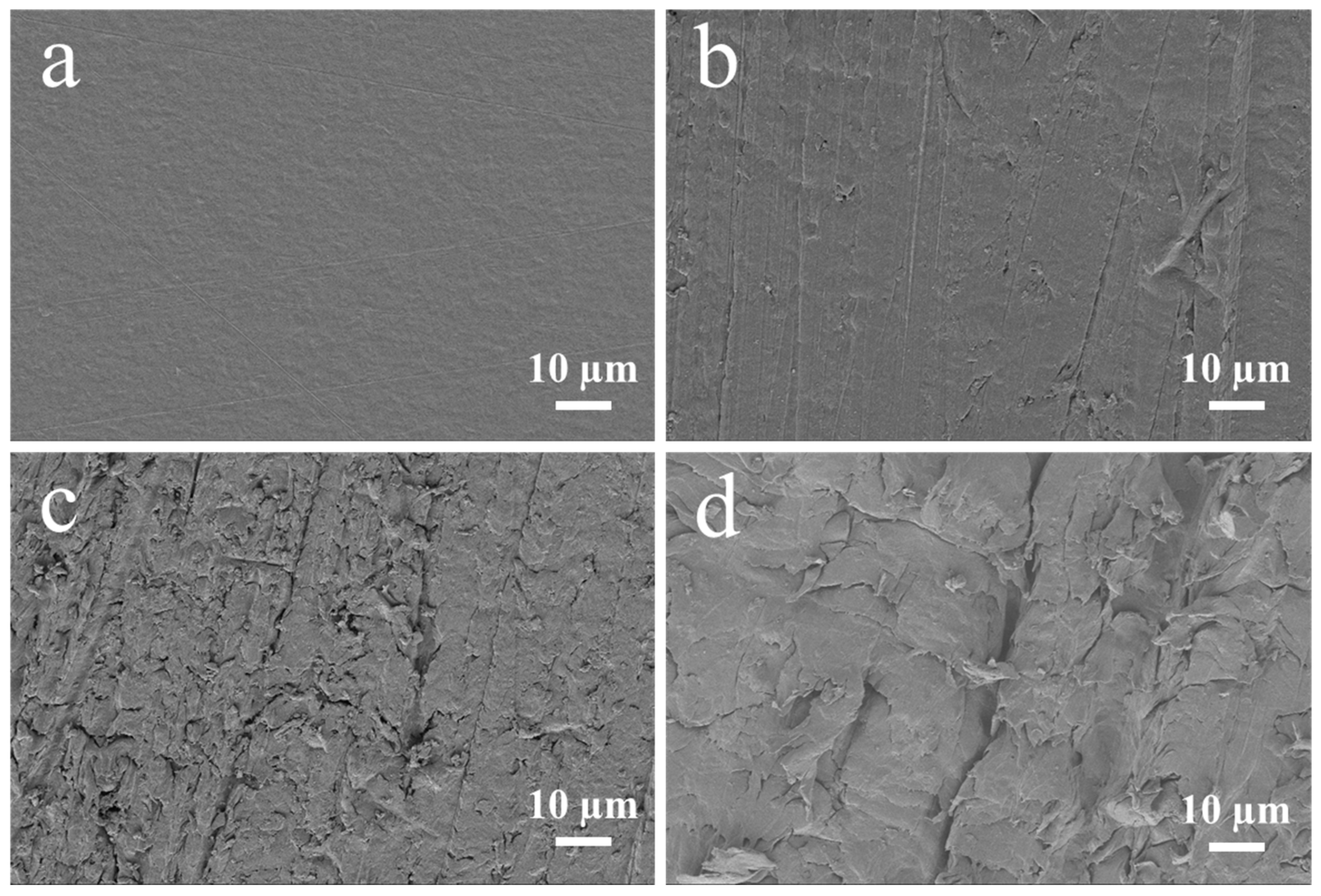
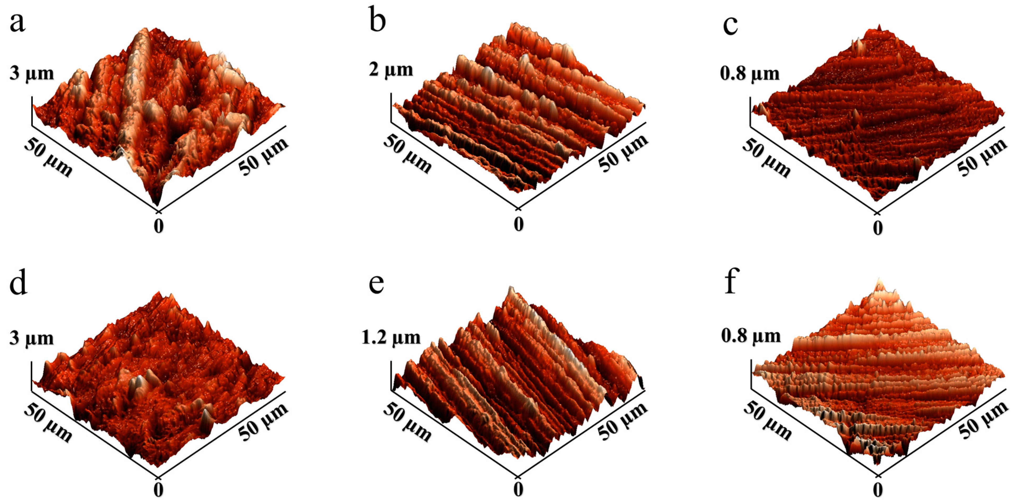
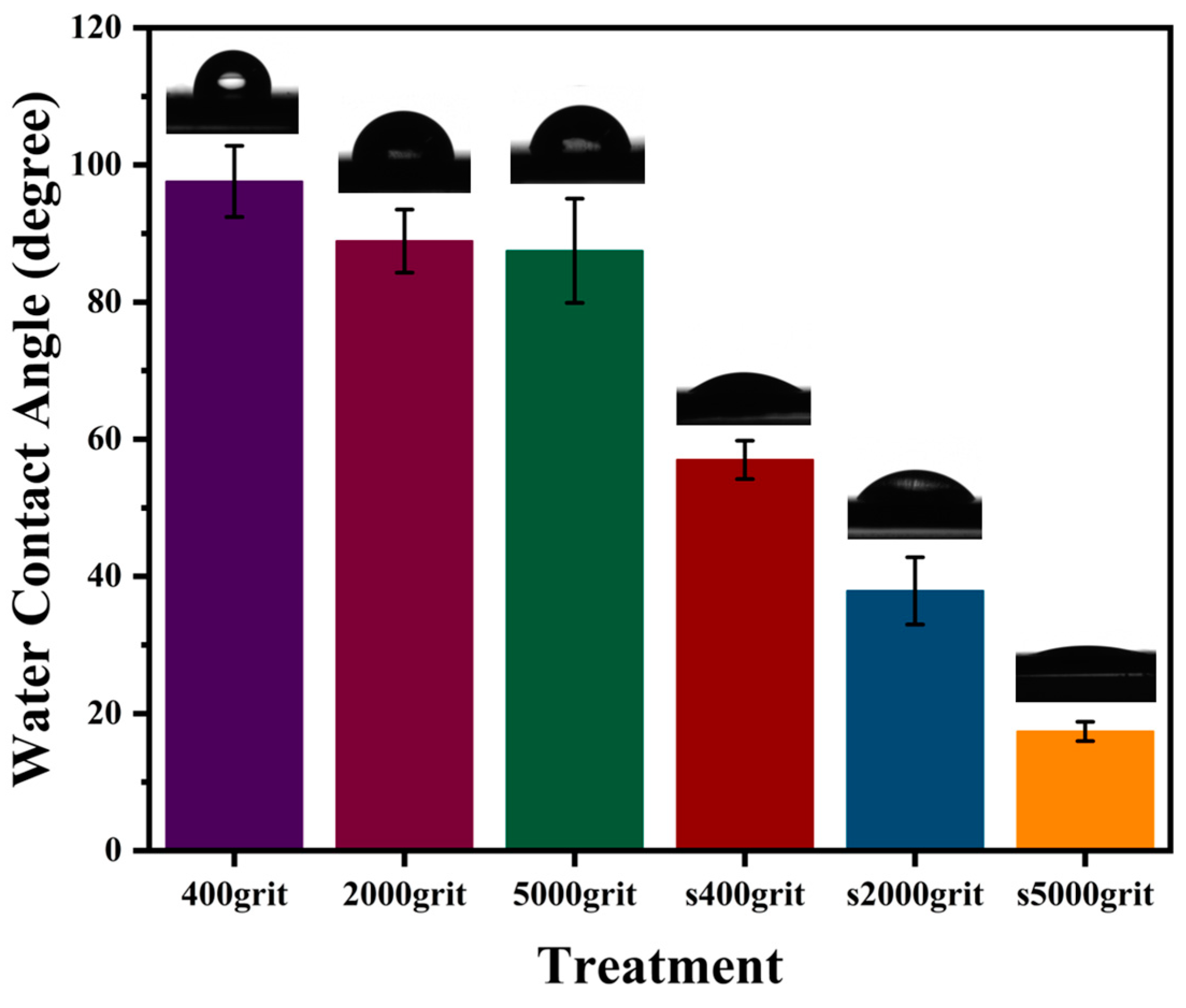
3.1. Characterization of PEEK Surfaces After Treatments

Surface treatment plays a critical role in enhancing the bonding strength between PEEK and PVTF. SEM images (Figure 2) illustrate the morphological changes of PEEK surfaces treated with different sandpapers. The untreated PEEK surface (Figure 2a) shows a smooth, featureless morphology. After treatment with sandpapers of decreasing grit size (from 5000-grit to 400-grit), the surface progressively becomes rougher (Figure 2b–d). AFM provides a detailed three-dimensional view of surface morphology, allowing for precise measurement of surface roughness and identifying changes induced by treatments. As shown in Figure 3a–c, the topography becomes progressively rougher as the grit size decreases, with deeper grooves and ridges evident in the 400-grit sample (Figure 3c). Figure 3d–f illustrate the corresponding AFM images of the same samples (Figure 3a–c) after the application of a silver coating. The silver layer slightly smoothens the surface by filling in minor grooves and irregularities. PEEK treated with 5000-grit sandpaper has the smoothest surface, with a roughness of 72.7 ± 14.6 nm, which is further reduced to 46.6 ± 5.7 nm after silver coating, demonstrating a substantial smoothing effect. PEEK treated with 2000-grit sandpaper exhibits a moderately rough surface, with a roughness of 265.6 ± 25.3 nm, which decreases to 224.9 ± 25.9 nm after silver coating. PEEK treated with 400-grit sandpaper, shows the highest roughness, measured at 450.5 ± 51.5 nm, and although the silver coating reduces the roughness to 332.8 ± 36.9 nm, it still retains the roughest surface (Table 1).
Surface roughness significantly influences a material’s wettability, affecting its hydrophilic or hydrophobic characteristics [39]. As shown in Figure 4, PEEK treated with 400-grit sandpaper exhibits the highest WCA at 97.6 ± 5.2°, indicating a hydrophobic surface due to its rough texture. The WCA decreases for PEEK treated with 2000-grit sandpaper, showing a value of 88.9 ± 4.6 degrees, and for 5000-grit sandpaper, with a value of 87.5 ± 7.6 degrees, reflecting a reduction in hydrophobicity as the surface becomes smoother. After applying a silver coating, all treated surfaces exhibit significantly lower WCAs, highlighting an increase in hydrophilicity. The 400-grit-treated PEEK shows a WCA reduction to 57.0 ± 2.8°, while the 2000-grit and 5000-grit-treated PEEK surfaces exhibit WCAs of 37.9 ± 4.9° and 17.4 ± 1.4° (Table 2).

3.2. Characterization of PVTF Coatings

The SEM image (Figure 5a) reveals a smooth and homogeneous surface, decorated with uniformly distributed PVTF whisker-like crystalline structures. These features are indicative of the beta-phase (β-phase) crystallization, which is the electroactive phase of PVTF [40]. The formation of this β-phase is attributed to the annealing process, which promotes uniform and enhanced crystallization throughout the film [40]. The cross-sectional SEM image provides further insights into the film’s thickness and internal structure (Figure 5b). The PVTF film exhibits a uniform thickness of approximately 125 μm, as indicated by the measurement in the image. The internal morphology shows a dense layer with no visible stratification or irregularities, suggesting uniform phase separation during the fabrication process.
The FTIR spectra of PVTF, PEEK substrates treated with varying grit sandpapers (400-grit, 2000-grit, 5000-grit), and polarized PVTF/PEEK samples (P1, P2, P3) are presented in Figure 6a. Three prominent β-phase absorption peaks are observed at 840 cm−1, 1285 cm−1, and 1400 cm−1 [41]. The peaks at 840 cm−1 and 1285 cm−1 are attributed to the symmetric stretching vibration of CF2, while the peak at 1400 cm−1 corresponds to the out-of-plane rocking vibration of CH2. The β-phase content of PVTF on untreated PEEK was calculated to be 70.2%. For PEEK substrates treated with different grit sandpapers, the β-phase content showed minimal variation: 72.3% for 400-grit, 73.4% for 2000-grit, and 71.6% for 5000-grit. However, the polarized PVTF/PEEK samples (P1, P2, P3) show a significant increase in β-phase content. Specifically, P1 achieved 85.8%, P2 reached 87.3%, and P3 exhibited the highest β-phase content at 87.7%. The β-phase content directly influences the piezoelectric properties of PVTF coatings, which are critical for bioelectrical stimulation in bone regeneration. The increase in β-phase enhances the surface charge density, which can promote osteoblast differentiation and improve cellular interactions. These findings highlight the importance of optimizing polarization conditions to maximize the electroactive performance of the coatings. The increase in β-phase content observed after polarization suggests that applying a higher voltage effectively promotes the formation of the electroactive phase. This is crucial for biomedical applications, as a higher β-phase fraction enhances the surface potential, which can positively influence cell-material interactions.
The XRD patterns (Figure 6b) reveal a strong β-phase diffraction peak at 2θ = 19.6° [42], corresponding to the (110)/(200) composite crystal planes of β phase, demonstrating excellent crystallinity in the samples. The grain sizes are calculated using the Debye–Scherrer equation. For the untreated sample, the grain size is 7.04 nm. After 400-grit treatment, it increases to 7.39 nm, while the 2000-grit and 5000-grit treatments result in sizes of 7.16 nm and 7.16 nm, respectively. Polarized samples further improved, with P1 (2 kV) at 7.24 nm, P2 (3 kV) at 8.37 nm, and P3 (4 kV) achieving the highest size of 8.44 nm. These results confirm that surface treatment and polarization effectively enhance β-phase crystallinity. The results indicate a clear trend of increased grain size with surface treatment and polarization. The progressive increase in grain size from P1 to P3 demonstrates the effectiveness of higher voltage polarization in improving structural organization within the samples. Grain size plays a crucial role in determining the mechanical stability and crystallization behavior of PVTF coatings. The results indicate that polarization at higher voltages (3 kV and 4 kV) led to an increase in grain size, suggesting improved crystallinity and better structural organization. This increase in grain size contributes to enhanced mechanical properties and coating durability, which are essential for biomedical applications.
From the DSC thermographs (Figure 6c), two distinct thermal transitions are observed for PVTF coated on PEEK surfaces treated with 400-grit, 2000-grit, and 5000-grit sandpapers. These transitions correspond to a crystallization temperature (Tc) between 80 °C and 105 °C and a melting temperature (Tm) around 155 °C. Identical Tc and Tm values across all samples suggest similar crystallization performance, regardless of the surface preparation. The crystallinity of each sample was calculated using a formula. The resulting crystallinity percentages for the untreated sample, 400-grit, 2000-grit, and 5000-grit samples were 71.05%, 72.6%, 71.8%, and 71.8%, respectively. These results suggest a slight improvement in crystallinity for the sandpaper-treated surfaces, with the 400-grit treatment achieving the highest crystallinity. The TGA thermographs (Figure 6d) indicate that major degradation occurs between 330 °C and 510 °C, with an average weight loss rate of 95%, confirming consistent thermal stability for PVTF on PEEK surfaces treated with different sandpapers.

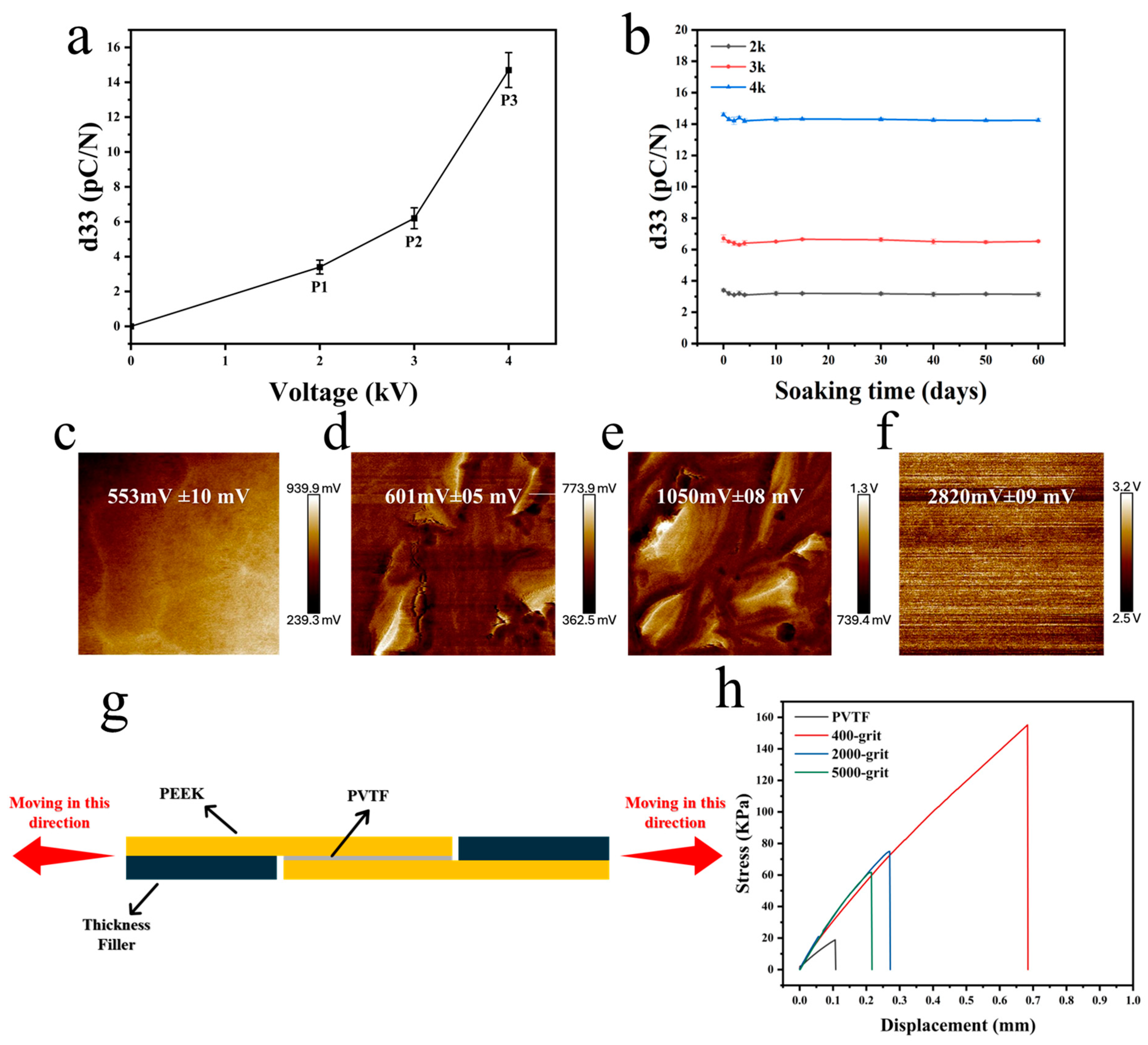
3.3. Electrical and Mechanical Properties of PVTF on PEEK

The piezoelectric coefficients (d33) of the PVTF coatings were measured under different applied voltages during polarization (Figure 7a). The d33 values increased with the polarization voltage, reaching the highest value of approximately 16 pC/N at 4 kV (P3). This suggests that higher polarization strengthens the electroactive properties of the PVTF coating, making it more effective in generating electrical stimulation, which is beneficial for biomedical applications such as bone regeneration. The stability of the piezoelectric coefficients was examined by immersing the PEEK/PVTF in PBS solution for 60 days (Figure 7b). The results indicated minimal degradation in d33 values, demonstrating the excellent long-term stability of the coatings under physiological conditions. As shown in Figure 7c–f, the unpoled PEEK/PVTF exhibited a relatively low surface potential of 553 mV ± 10 mV, whereas PEEK/PVTF polarized at 2 kV (P1), 3 kV (P2), and 4 kV (P3) showed progressively higher surface potentials of 601 mV ± 5 mV, 1050 mV ± 8 mV, and 2820 mV ± 9 mV. The increase in surface potential with higher polarization suggests that a stronger electroactive response can be maintained on the material surface. This is particularly relevant for biomedical implants, where surface potential plays a role in promoting cellular interactions and tissue regeneration. The bonding strength between the PVTF coatings and the PEEK substrate was assessed using a material testing machine, as illustrated in the schematic diagram in Figure 7g. Figure 7h and Table 3 show the bonding strength results for samples treated with sandpapers of varying grit sizes (400-grit, 2000-grit, and 5000-grit). The 400-grit-treated sample exhibited the highest bonding strength of 155.2 ± 9.2 kPa, followed by the 2000-grit and 5000-grit samples, with bonding strengths of 75.0 ± 6.9 kPa and 61.7 ± 5.8 kPa. The PVTF sample without substrate treatment showed the lowest bonding strength at 18.9 ± 3.6 kPa. Among the different surface treatments, the 400-grit-treated PEEK showed the highest adhesion strength with PVTF. This indicates that increasing surface roughness enhances mechanical interlocking and bonding, which is essential for the durability of electroactive coatings in biomedical applications.

3.4. Biocompatibility and Osteogenesis of PEEK/PVTF

To explore the influence of surface polarization on cell adhesion and proliferation, bone marrow mesenchymal stem cells (BMSCs) were seeded onto the surfaces on PVTF coatings for 1 and 3 days, and cell viability was assessed using the CCK-8 assay. The optical density (OD) values at 450 nm, as shown in Figure 8, revealed the effects of surface polarization on BMSC behavior. After 1 day of culture, the OD values indicated that the polarized samples significantly enhanced cell adhesion compared to the non-polarized control. The P3-polarized samples exhibited the best cell adhesion, followed by the P2-polarized samples, while the P1-polarized samples showed adhesion levels slightly higher than the non-polarized control. After 3 days, all polarized samples showed significant improvement in cell proliferation, with the 4 kV-polarized surface achieving the highest OD value. The P3 group exhibited significantly higher cell viability compared to the unpolarized and lower polarization groups, indicating that a higher surface potential enhances BMSC adhesion and proliferation. This suggests that optimizing polarization voltage can improve the biocompatibility of electroactive coatings. As shown in Figure 9, ALP activity significantly increased for all polarized samples compared to unpolled control at both time points. After 7 days of culture, the P3 sample exhibited the highest ALP activity, followed by P2 and P1. The unpolarized PEEK/PVTF coating showed the lowest ALP activity. The same trend was observed after 14 days, with the P3 coating demonstrating a substantial increase in ALP activity, indicating enhanced osteogenic differentiation over time. The ALP activity results further confirm that the P3 group has the highest osteogenic differentiation potential. Combined with its higher surface potential, this suggests that an increased surface potential plays a positive role in promoting osteogenesis, making highly polarized PVTF coatings promising candidates for bone regeneration applications. The results indicate that none of the tested groups exhibited significant cytotoxicity, and among them, the P3 group demonstrated the best biocompatibility, as evidenced by the highest cell viability and osteogenic differentiation. However, we acknowledge that ALP activity serves as an early marker of osteogenesis and does not fully capture the later stages of bone formation. Further investigations, including mineralization studies and the quantification of osteocalcin and osteopontin, are necessary to confirm the long-term osteogenic effects of the developed coatings. Additionally, in vivo studies will be required to evaluate their long-term bone integration and biological performance in a physiological environment. These future investigations will provide a more comprehensive understanding of the osteogenic potential of PVTF-coated PEEK implants and further validate their application in orthopedic implants.

4. Conclusions

In this work, PEEK surfaces were modified through physical treatments to improve the adhesion strength of PVTF coatings, and the electroactive properties of these coatings were successfully enhanced. Additionally, the biocompatibility and osteogenesis potential of the PEEK/PVTF composite were assessed. The conclusion points are as follows:
  • Physical modification of the PEEK surface effectively enhanced the bonding strength between PEEK and PVTF coatings. These improvements in adhesion were achieved without compromising the electroactive properties of the PVTF coatings. The physical treatments resulted in a significant increase in adhesion strength, making the composite more durable for biomedical applications.
  • After polarization, the PEEK/PVTF composite exhibited an increased β-phase content, with a noticeable enhancement in the d33 value. This indicates a substantial improvement in the electroactive properties of the PVTF coatings. Moreover, the surface potential of the PVTF coatings remained stable, ensuring consistent electroactive behavior suitable for osteogenesis.
  • The PEEK/PVTF composite demonstrated excellent biocompatibility, promoting cell proliferation and osteogenic differentiation. These favorable biological responses suggest that the PEEK/PVTF composite has strong potential for promoting bone regeneration and could serve as an advanced material for orthopedic implants. However, while our findings suggest that PVTF-coated PEEK implants exhibit enhanced osteogenic differentiation potential, further studies are required to explore their long-term bone integration and the molecular mechanisms involved. Future research should focus on mineralization studies, late-stage osteogenic markers, and in vivo evaluations to provide a more comprehensive assessment of the material’s effectiveness for orthopedic applications.

Author Contributions

Conceptualization, K.C. and A.Y.; methodology, A.Y. and H.L.; investigation, A.Y. and X.X.; data curation, A.Y. and L.M.; writing—original draft preparation, A.Y.; writing—review and editing, K.C.; visualization, A.Y. and X.X.; funding acquisition, K.C. All authors have read and agreed to the published version of the manuscript.

Funding

This work was financially supported by the National Natural Science Foundation of China (Grant No. 52271252, 32271373 and U24A20762), Key Research and Development Program of Zhejiang Province (2021C03061), and the Postdoctoral Fellowship Program of China Postdoctoral Science Foundation (GZC20232243).

Institutional Review Board Statement

Not applicable.

Informed Consent Statement

Not applicable.

Data Availability Statement

The authors confirm that the data supporting the findings of this study are available within the article.

Conflicts of Interest

The authors declare no conflicts of interest.

References

  1. Cauda, V.; Stassi, S.; Bejtka, K.; Canavese, G. Nanoconfinement: An effective way to enhance PVDF piezoelectric properties. ACS Appl. Mater. Interfaces 2013, 5, 6430–6437. [Google Scholar] [CrossRef] [PubMed]
  2. Poon, K.K.; Wurm, M.C.; Evans, D.M.; Einarsrud, M.-A.; Lutz, R.; Glaum, J. Biocompatibility of (Ba,Ca)(Zr,Ti)O3 piezoelectric ceramics for bone replacement materials. J. Biomed. Mater. Res. Part. B Appl. Biomater. 2020, 108, 1295–1303. [Google Scholar] [CrossRef] [PubMed]
  3. Sundar, U.; Lao, Z.; Cook-Chennault, K. Investigation of Piezoelectricity and Resistivity of Surface Modified Barium Titanate Nanocomposites. Polymers 2019, 11, 2123. [Google Scholar] [CrossRef] [PubMed]
  4. Namsheer, K.; Rout, C.S. Conducting polymers: A comprehensive review on recent advances in synthesis, properties and applications. RSC Adv. 2021, 11, 5659–5697. [Google Scholar] [CrossRef]
  5. Lakard, B. Electrochemical Biosensors Based on Conducting Polymers: A Review. Appl. Sci. 2020, 10, 6614. [Google Scholar] [CrossRef]
  6. Acri, T.M.; Shin, K.; Seol, D.; Laird, N.Z.; Song, I.; Geary, S.M.; Chakka, J.L.; Martin, J.A.; Salem, A.K. Tissue Engineering for the Temporomandibular Joint. Adv. Healthc. Mater. 2019, 8, 1801236. [Google Scholar] [CrossRef]
  7. Xue, N.; Ding, X.; Huang, R.; Jiang, R.; Huang, H.; Pan, X.; Min, W.; Chen, J.; Duan, J.-A.; Liu, P.; et al. Bone Tissue Engineering in the Treatment of Bone Defects. Pharmaceuticals 2022, 15, 879. [Google Scholar] [CrossRef] [PubMed]
  8. Jin, H.; Ji, Y.; Cui, Y.; Xu, L.; Liu, H.; Wang, J. Simvastatin-Incorporated Drug Delivery Systems for Bone Regeneration. ACS Biomater. Sci. Eng. 2021, 7, 2177–2191. [Google Scholar] [CrossRef] [PubMed]
  9. Jiang, C.; Fu, J.; Zhang, H.; Hua, Y.; Cao, L.; Ren, J.; Zhou, M.; Jiang, F.; Jiang, X.; Ling, S. Self-Reinforcing Ionogel Bioadhesive Interface for Robust Integration and Monitoring of Bioelectronic Devices with Hard Tissues. Adv. Mater. 2024, 2413028. [Google Scholar] [CrossRef] [PubMed]
  10. D’Alessandro, D.; Ricci, C.; Milazzo, M.; Strangis, G.; Forli, F.; Buda, G.; Petrini, M.; Berrettini, S.; Uddin, M.J.; Danti, S.; et al. Piezoelectric Signals in Vascularized Bone Regeneration. Biomolecules 2021, 11, 1731. [Google Scholar] [CrossRef]
  11. Jacob, J.; More, N.; Kalia, K.; Kapusetti, G. Piezoelectric smart biomaterials for bone and cartilage tissue engineering. Inflamm. Regen. 2018, 38, 2. [Google Scholar] [CrossRef] [PubMed]
  12. Todd, E.A.; Mirsky, N.A.; Silva, B.L.; Shinde, A.R.; Arakelians, A.R.L.; Nayak, V.V.; Marcantonio, R.A.; Gupta, N.; Witek, L.; Coelho, P.G. Functional Scaffolds for Bone Tissue Regeneration: A Comprehensive Review of Materials, Methods, and Future Directions. J. Funct. Biomater. 2024, 15, 280. [Google Scholar] [CrossRef]
  13. Zheng, Y.; Zhao, L.; Li, Y.; Zhang, X.; Zhang, W.; Wang, J.; Liu, L.; An, W.; Jiao, H.; Ma, C. Nanostructure Mediated Piezoelectric Effect of Tetragonal BaTiO3 Coatings on Bone Mesenchymal Stem Cell Shape and Osteogenic Differentiation. Int. J. Mol. Sci. 2023, 24, 4051. [Google Scholar] [CrossRef]
  14. Wang, Y.; Dargusch, M.S. Optimisation and material considerations of piezoelectric implants for cardiac applications. Curr. Opin. Solid. State Mater. Sci. 2025, 34, 101211. [Google Scholar] [CrossRef]
  15. Saleem, A.; Frormann, L.; Iqbal, A. High performance thermoplastic composites: Study on the mechanical, thermal, and electrical resistivity properties of carbon fiber-reinforced polyetheretherketone and polyethersulphone. Polym. Compos. 2007, 28, 785–796. [Google Scholar] [CrossRef]
  16. Wang, F.; Roovers, J.J.M. Functionalization of poly (aryl ether ether ketone)(PEEK): Synthesis and properties of aldehyde and carboxylic acid substituted PEEK. Macromolecules 1993, 26, 5295–5302. [Google Scholar] [CrossRef]
  17. Gu, X.; Sun, X.; Sun, Y.; Wang, J.; Liu, Y.; Yu, K.; Wang, Y.; Zhou, Y. Bioinspired Modifications of PEEK Implants for Bone Tissue Engineering. Front. Bioeng. Biotechnol. 2021, 8, 631616. [Google Scholar] [CrossRef]
  18. Eschbach, L.J.I. Nonresorbable polymers in bone surgery. Injury 2000, 31, 22–27. [Google Scholar] [CrossRef] [PubMed]
  19. Yu, X.; Ibrahim, M.; Liu, Z.; Yang, H.; Tan, L.; Yang, K. Biofunctional Mg coating on PEEK for improving bioactivity. Bioact. Mater. 2018, 3, 139–143. [Google Scholar] [CrossRef] [PubMed]
  20. Oyane, A.; Nakamura, M.; Sakamaki, I.; Shimizu, Y.; Miyata, S.; Miyaji, H. Laser-assisted wet coating of calcium phosphate for surface-functionalization of PEEK. PLoS ONE 2018, 13, 206524. [Google Scholar] [CrossRef]
  21. Cvrček, L.; Krčil, J.; Musílková, J.; Musílková, V.; Bačáková, L.; Nehasil, V.; Denk, F.; Čejka, Z. Nanostructured TiNb coating improves the bioactivity of 3D printed PEEK. Mater. Des. 2022, 224, 111312. [Google Scholar] [CrossRef]
  22. Li, W.; Sang, L.; Jian, X.; Wang, J. Influence of sanding and plasma treatment on shear bond strength of 3D-printed PEI, PEEK and PEEK/CF. Int. J. Adhes. Adhes. 2020, 100, 102614. [Google Scholar] [CrossRef]
  23. Liu, C.; Bai, J.; Wang, Y.; Chen, L.; Wang, D.; Ni, S.; Liu, H. The effects of three cold plasma treatments on the osteogenic activity and antibacterial property of PEEK. Dent. Mater. 2021, 37, 81–93. [Google Scholar] [CrossRef]
  24. Fedel, M.; Micheli, V.; Thaler, M.; Awaja, F. Effect of nitrogen plasma treatment on the crystallinity and self-bonding of polyetheretherketone (PEEK) for biomedical applications. Polym. Adv. Technol. 2020, 31, 240–247. [Google Scholar] [CrossRef]
  25. Van Horn, M.R.; Beard, R.; Bucklen, B. P6. A roughened 3D-printed surface enhances stem cell proliferation and osteoblast differentiation. Spine J. 2020, 20, S150. [Google Scholar] [CrossRef]
  26. Fukuda, N.; Kanazawa, M.; Tsuru, K.; Tsuchiya, A.; Sunarso; Toita, R.; Mori, Y.; Nakashima, Y.; Ishikawa, K. Synergistic effect of surface phosphorylation and micro-roughness on enhanced osseointegration ability of poly(ether ether ketone) in the rabbit tibia. Sci. Rep. 2018, 8, 16887. [Google Scholar] [CrossRef] [PubMed]
  27. Luo, C.; Liu, Y.; Peng, B.; Chen, M.; Liu, Z.; Li, Z.; Kuang, H.; Gong, B.; Li, Z.; Sun, H. PEEK for Oral Applications: Recent Advances in Mechanical and Adhesive Properties. Polymers 2023, 15, 386. [Google Scholar] [CrossRef] [PubMed]
  28. Ge, Y.; Hu, L.; Liu, J.; Ma, F.; Zhang, J.; Wang, Y.; Tang, B.; Cao, S. Peek@ZIF-8(CEL) as a Novel Bone Implant for Large Defect Repair and Enhanced Bone Healing via a Long-Term Stable Bioactive Releaser. ACS Appl. Mater. Interfaces 2024, 16, 44127–44138. [Google Scholar] [CrossRef] [PubMed]
  29. Hu, G.; Zhu, Y.; Xu, F.; Ye, J.; Guan, J.; Jiang, Y.; Di, M.; Li, Z.; Guan, H.; Yao, X. Comparison of surface properties, cell behaviors, bone regeneration and osseointegration between nano tantalum/PEEK composite and nano silicon nitride/PEEK composite. J. Biomater. Sci. Polym. Ed. 2022, 33, 35–56. [Google Scholar] [CrossRef]
  30. Kadiyala, A.K.; Bijwe, J.; Kalappa, P. Investigations on influence of nano and micron sized particles of SiC on performance properties of PEEK coatings. Surf. Coat. Technol. 2018, 334, 124–133. [Google Scholar] [CrossRef]
  31. Frankenberger, T.; Graw, C.L.; Engel, N.; Gerber, T.; Frerich, B.; Dau, M. Sustainable Surface Modification of Polyetheretherketone (PEEK) Implants by Hydroxyapatite/Silica Coating—An In Vivo Animal Study. Materials 2021, 14, 4589. [Google Scholar] [CrossRef]
  32. Shi, X.; Wang, Z.; Guo, M.; Wang, Y.; Bi, Z.; Li, D.; Zhang, P.; Liu, J. PRP coating on different modified surfaces promoting the osteointegration of polyetheretherketone implant. Front. Bioeng. Biotechnol. 2023, 11, 1283526. [Google Scholar] [CrossRef] [PubMed]
  33. Pandey, M.; Mairal, A.; Gupta, H.; Kumar, A.; Bhattacharya, S. Rapid surface modification of PEEK by ambient temperature sulfonation for high shelf-life biomedical applications. Surf. Interfaces 2024, 54, 105117. [Google Scholar] [CrossRef]
  34. Kumar, M.; Kumari, P. P(VDF-TrFE)/ZnO nanocomposite synthesized by electrospinning: Effect of ZnO nanofiller on physical, mechanical, thermal, rheological and piezoelectric properties. Polym. Bull. 2023, 80, 4859–4878. [Google Scholar] [CrossRef]
  35. Gutiérrez-Sánchez, G.; Hernando-García, J.; Victor, R.-D.; Dura, O.J.; de la Torre, M.A.L.; Sánchez-Rojas, J.L. Comparative assessment of PVDF and PVDF-TrFE piezoelectric polymers for flexible actuators applications. In Proceedings of the Proc.SPIE; 2017; pp. 148–153. Available online: https://www.spiedigitallibrary.org/conference-proceedings-of-spie/10246/102460N/Comparative-assessment-of-PVDF-and-PVDF-TrFE-piezoelectric-polymers-for/10.1117/12.2266559.short%2031%20May%202017 (accessed on 31 May 2017).
  36. Mohammadpourfazeli, S.; Arash, S.; Ansari, A.; Yang, S.; Mallick, K.; Bagherzadeh, R. Future prospects and recent developments of polyvinylidene fluoride (PVDF) piezoelectric polymer; fabrication methods, structure, and electro-mechanical properties. RSC Adv. 2023, 13, 370–387. [Google Scholar] [CrossRef]
  37. Zhang, C.; Liu, W.; Cao, C.; Zhang, F.; Tang, Q.; Ma, S.; Zhao, J.; Hu, L.; Shen, Y.; Chen, L. Modulating Surface Potential by Controlling the β Phase Content in Poly(vinylidene fluoridetrifluoroethylene) Membranes Enhances Bone Regeneration. Adv. Healthc. Mater. 2018, 7, 1701466. [Google Scholar] [CrossRef] [PubMed]
  38. Barbosa, F.; Alberte, P.S.; Garrudo, F.F.F.; Carvalho, M.S.; Pascoal-Faria, P.; Ferreira, F.C.; Silva, J.C. Piezoelectric PVDF-TrFE/Hydroxyapatite Nanofibers for Bone Tissue Engineering. Mater. Proc. 2022, 8, 66. [Google Scholar] [CrossRef]
  39. Maghsoudy-Louyeh, S.; Ju, H.S.; Tittmann, B.R. Surface roughness study in relation with hydrophilicity/hydrophobicity of materials using atomic force microscopy. AIP Conf. Proc. 2010, 1211, 1487–1492. [Google Scholar] [CrossRef]
  40. Ruan, L.; Yao, X.; Chang, Y.; Zhou, L.; Qin, G.; Zhang, X. Properties and Applications of the β Phase Poly(vinylidene fluoride). Polymers 2018, 10, 228. [Google Scholar] [CrossRef]
  41. Cai, X.; Lei, T.; Sun, D.; Lin, L. A critical analysis of the α, β and γ phases in poly(vinylidene fluoride) using FTIR. RSC Adv. 2017, 7, 15382–15389. [Google Scholar] [CrossRef]
  42. Zhang, C. Large-Scale Fabrication of High β-Phase PVDF Films with Enhanced Piezoelectric and Electrode Formation Properties. J. Mater. Eng. Perform. 2024, 1–14. [Google Scholar] [CrossRef]
Figure 1. Schematic of the PEEK/PVTF coating preparation process.
Coatings 15 00261 g001
Figure 2. SEM images of PEEK and PEEK after surface treatments: (a) PEEK without treatment, (b) 5000-grit sandpaper, (c) 2000-grit sandpaper, and (d) 400-grit sandpaper.
Coatings 15 00261 g002
Figure 3. AFM images of PEEK after surface treatments and silver coating: (a) 5000-, (b) 2000-, and (c) 400-grit sandpaper before silver coating; and (d) 5000-, (e) 2000-, and (f) 400-grit sandpaper after silver coating.
Coatings 15 00261 g003
Figure 4. WCA of PEEK after surface treatments and silver coating.
Coatings 15 00261 g004
Figure 5. SEM images of PEEK/PVTF: (a) surface and (b) cross-section.
Coatings 15 00261 g005
Figure 6. (a) FTIR spectra, (b) XRD patterns, (c) DSC thermograms, and (d) TGA thermograms of PVTF on PEEK.
Coatings 15 00261 g006
Figure 7. (a) Piezoelectric coefficients (d33) of PVTF coatings, (b) piezoelectric coefficients of PVTF coatings immersed in PBS solution for 60 days. Surface potential of PVTF coatings after polarization (c) unpoled, (d) P1, (e) P2, (f) P3, (g) schematic diagram of bonding strength measurement, (h) bonding strength of PEEK/PVTF after PEEK surface treatment and silver coating.
Coatings 15 00261 g007
Figure 8. Cell viability of PEEK/PVTF measured by CCK-8 assay at 1 and 3 days: comparison among unpoled, P2, and P3 based on OD values, n = 6, * p < 0.05, ** p < 0.01, *** p < 0.001.
Coatings 15 00261 g008
Figure 9. ALP activities of BMSCs cultured on unpolarized and polarized PEEK/PVTF coatings (P1, P2, P3) after 7 days and 14 days, n = 6, * p < 0.05, ** p < 0.01, *** p < 0.001.
Coatings 15 00261 g009
Table 1. Roughness of PEEK after surface treatments and silver coating.
TreatmentRoughness (nm)
400-grit450.5 ± 51.5
2000-grit265.6 ± 25.3
5000-grit72.7 ± 14.6
Silver coating 400-grit332.8 ± 36.9
Silver coating 2000-grit224.9 ± 25.9
Silver coating 5000-grit46.6 ± 5.7
Table 2. WCA of PEEK after surface treatments and silver coating.
TreatmentWater Contact Angle (degree)
400-grit97.6 ± 5.2
2000-grit88.9 ± 4.6
5000-grit87.5 ± 7.6
Silver coating 400-grit57.0 ± 2.8
Silver coating 2000-grit37.9 ± 4.9
Silver coating 5000-grit17.4 ± 1.4
Table 3. Bonding strength of PEEK/PVTF after PEEK surface treatment and silver coating.
TreatmentBonding Strength (KPa)
400-grit155.2 ± 9.2
2000-grit75.0 ± 6.9
5000-grit61.7 ± 5.8
PVTF18.9 ± 3.6
Disclaimer/Publisher’s Note: The statements, opinions and data contained in all publications are solely those of the individual author(s) and contributor(s) and not of MDPI and/or the editor(s). MDPI and/or the editor(s) disclaim responsibility for any injury to people or property resulting from any ideas, methods, instructions or products referred to in the content.

