Abstract
High-quality diamond-like carbon (DLC) films are renowned for their exceptional hardness, low friction coefficient, and superior chemical stability. These properties make DLC films exceptionally suitable for protective coatings in optical, mechanical, aerospace, and military applications. Thick DLC films with outstanding mechanical properties were deposited on DC53 die steel using a mixed energy carbon plasma generated by a filtered cathodic vacuum arc (FCVA) device. The structural, mechanical, tribological, and optical properties of the films were tested by Raman, surface morphology instrument, Vickers Indenter, tribometer, and UV-VIS spectrophotometry. The results indicated that 14 µm tetrahedral amorphous carbon (ta-C) films with a good combination with DC53 die steel substrate were obtained. The hardness was 9415 HV, which is close to that of diamond films. The fracture toughness was 4 MPa·m1/2. The friction coefficient was 0.0898, and the optical band gap was 3.12 eV.
1. Introduction
Tetrahedral amorphous diamond (ta-C) film refers to a hydrogen-free diamond-like carbon (DLC) film with an sp3 bond content exceeding 70% [1,2]. Because of its excellent properties, such as exceptional hardness, low friction coefficient, and superior chemical stability, ta-C film is ideal for use as a wear-resistant surface protection film and has broad application prospects in the fields of optics, mechanics, aerospace, and the military [3,4,5,6,7,8]. Compared with hydrogen-containing amorphous carbon film (a-C:H), the preparation process of ta-C film does not require gas, making the process simpler and safer. Additionally, the mechanical, optical, thermal-stability, and electrical properties of ta-C films are superior to those of a-C:H films [1,9]. In contrast to diamond film, ta-C film can be deposited at room temperature, and its structure and properties can be tailored according to actual needs, making it easier to produce in large quantities and reducing costs.
With high hardness, smooth surfaces, low friction coefficients, and excellent wear resistance, ta-C films serve as effective wear-resistant coatings that significantly protect components and molds, thereby extending their service life. However, the deposition of ta-C films generates very high internal stresses, resulting in weak film–substrate bonding, particularly with steel substrates. This significantly limits the film’s thickness and its range of applications [10].
Common methods to reduce film stress include metal doping, heat treatment, and alternate deposition of soft and hard layers [11]. However, metal doping affects the structure and hardness of the film; heat treatment is unsuitable for temperature-sensitive substrates, limiting its application range; and alternate layer deposition increases process complexity and reduces deposition efficiency. Because of the aforementioned challenges, the currently produced high-quality ta-C films are typically limited to thicknesses of a few hundred nanometers, making it difficult to achieve micron-scale thicknesses with comparable quality. Therefore, further research is essential to explore the balance between residual stress and the performance of thick ta-C films. Marcus Kennedy in Germany fabricated a 20 µm thick a-C film with a hardness of only 5000 HV [12]. Various deposition techniques have been employed to fabricate a-C films, such as ion beam deposition, sputtering, and pulsed laser deposition. Among these methods, the filtered cathodic vacuum arc (FCVA) technique stands out because of its ability to effectively filter out most neutral atoms and macro ions, achieving a high ionization rate and enabling the production of high plasma density. The controllable ion energy and high ionization rate in FCVA contribute to the deposition of high-quality ta-C films [1,13]. Recently, our research group integrated high-voltage pulse technology into FCVA to reduce stress at the expense of sp3 content. For instance, Shuai Wu prepared a-C films exhibiting low residual stress of 1.79 GPa with a hardness of 51 GPa, and Yongqing Shen achieved a hardness of 27.3 GPa in 50 µm DLC films by adjusting the pulse frequency (10–50 Hz) [8,13,14]
In this research, we attempted to optimize the fabrication process of ta-C films by adjusting the substrate negative bias and incorporating duty cycles, aiming to reduce the film residual stress, thereby enabling the growth of thick ta-C films on DC53 steel substrates. By optimizing these parameters, we sought to achieve a ta-C film that is both hard and tough, with strong adhesion to the substrate, thereby advancing the development of ta-C films with enhanced mechanical properties for practical applications.
2. Experimental Details
2.1. Materials and Methodology
The deposition process was carried out using an FCVA system, which included three primary components: a vacuum system, a cathodic arc source, and a magnetic filtration system [8,13,15]. The cathodic arc source utilized high-purity (99.999%) graphite as the cathode material, and the base pressure was maintained at 3 × 10⁻³ Pa. A dual-curved magnetic filtration system was employed to effectively filter out macroparticles and neutral species, ensuring high film quality. Additionally, a positive bias was introduced to the curved magnetic duct to further focus the ion beam and improve ion transport efficiency. This optimized filtration process significantly reduced the inclusion of macroparticles in the deposited films. A pulsed negative bias was applied to the substrate with an adjustable duty cycle, which influenced and modified the ion energy during the deposition process.
The n-type single crystal silicon wafers (110 orientation), measuring 30 mm × 20 mm and having a thickness of 0.5 mm, were employed to investigate the effects of duty cycle and negative bias on film formation characteristics. For optical bandgap measurements, quartz crystals measuring 10 mm × 10 mm and 2 mm thick served as substrates. The thick film substrate material was DC53 die steel, 30 mm × 40 mm and 10 mm thick, which was polished using water sandpaper (up to 2000 grit) and diamond polishing paste. Prior to deposition, all substrates were sequentially cleaned using acetone and ethanol via ultrasonic cleaning. Prior to the formal deposition, high-energy ions were used for cleaning and the deposition of a transition layer, which enhanced the film–substrate adhesion. For the silicon and quartz substrates, this step lasted for 1 min, while for the DC53 die steel substrate, it took 8.5 min. During this process, the voltage gradually transitioned from 800 V to 400 V concurrently with a decrease in the duty cycle from 90% to 0%. After the deposition of the transition layer, formal deposition was carried out. The arc current of the carbon cathode was set to 100 A, with a magnetic field current of 1.5 A near the arc source and 2.0 A near the deposition target chamber. The bending tube positive bias was set at 15 V. Films were prepared by changing the negative bias, duty cycle, and deposition time. During the preparation of the thick DLC film, it should be noted that each carbon cathode could only sustain an arc for approximately three hours. Consequently, the deposition process had to be interrupted every three hours to replace the carbon source. This procedure ensured a continuous and stable deposition environment, allowing for the consistent growth of the DLC film.
2.2. Specimen Characterization
The film thickness and curvature radius were measured by a Talysurf 5P-120 surface topography instrument (Taylor Hobson, Berwyn, IL, USA). The Stoney formula was used to obtain the residual stress of the film [16]. The formula is given below:
where Es, νs, and ts represent elastic modulus, Poisson’s ratio, and substrate thickness, respectively. d is the film thickness; r0 and r denote the radius of curvature before and after deposition, respectively.
The film thickness was also determined using an S-4800 field emission scanning electron microscope (SEM). Raman spectroscopy was conducted on the sample surface with a LabRAM Aramis laser confocal micro-Raman spectrometer (Horiba Jobin Yvon, Montpellier, France) operating at a visible wavelength of 532 nm. Rockwell hardness measurements were taken with an HR-150 Rockwell hardness tester (MetalReader, Yantai, China). Vickers hardness was assessed using a Vickers hardness tester (Shanghai Taiming Optical Instrument Co., Ltd., Shanghai, China), and hardness values were computed using Equation (2) [17].
where m is the test force and l is the diagonal length of the indentation.
Fracture toughness was derived from Equation (3) [18,19]. Friction properties were evaluated with a ball-on-disk tribometer, where the counterface material was Si3N4, the applied load was 3 N, the rotational speed was 200 rpm, and the friction radius was 3 mm. The optical bandgap was determined using a SPECORD200 UV-Vis spectrophotometer.
where E is the elastic modulus, F is the load, and c is the crack length.
3. Results and Discussion
3.1. Influence of Negative Bias on the Properties of ta-C Films
Figure 1 shows the residual stress of ta-C films deposited on silicon substrates under different negative biases, all at a consistent duty cycle of 20%. The deposition process lasted 5 min, and the film thickness, measured with a surface topography instrument, was found to be 110–140 nm. The Stoney formula was used to calculate the film residual stress. As the negative bias increases, the residual stress initially decreases before rising again. The data show that residual stress reaches its minimum at a bias of 400 V, followed by 300 V. Raman spectra for the films deposited at 300 V and 400 V (Figure 2) indicate that the ID/IG ratio at 300 V is 0.25, significantly lower than the 0.40 observed at 400 V. For amorphous carbon films, the G peak and D peak both provide information about the sp2 cluster structure in films. The G peak arises from the stretching vibrations of sp2 hybridized carbon in both ring and chain configurations, while the D peak is associated with the breathing vibrations of sp2 ring structures. The relationship between the ratios of D and G peaks (ID/IG) and the graphite cluster size (La) is described by Equation (4).
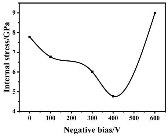
Figure 1.
Residual stress of ta-C films deposited in different negative biases.
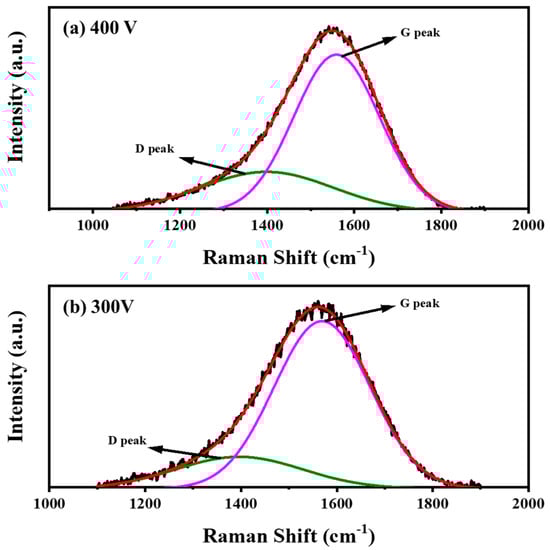
Figure 2.
Raman curves of ta-C film on silicon chip in 400 V negative bias (a) and 300 V (b).
This indicates that at a negative bias of 300 V, the graphite clusters are smaller, leading to a higher content of sp3 bonds. Therefore, to achieve high-performance thick films of amorphous diamond-like carbon, it is recommended to use the negative bias of 300 V during the deposition process.
3.2. Influence of Duty Cycles on the Properties of ta-C Films
Figure 3 displays the Raman curves of carbon films deposited for 5 min at the substrate bias of −300 V under various duty cycles. Figure 4 compares the D/G band characteristics (peak positions, FWHM), residual stress, and ID/IG ratios extracted from Figure 3’s Raman data for ta-C films grown at fixed bias with modulated duty cycles. The findings indicate that both residual stress and ID/IG ratios vary significantly with changes in duty cycle. This suggests that the mixed energy of the ion beam has a substantial impact on the film residual stress and the sp3 content. By optimizing parameters such as negative bias and duty cycle, it is possible to effectively control the energy of the ion beam, thereby reducing the residual stress of the films while simultaneously increasing the sp3 content. This optimization is crucial for achieving high-quality amorphous diamond films with micron-level thickness. Notably, at a duty cycle of 20%, the sample exhibited the lowest ID/IG ratio and showed relatively low residual stress. Under the conditions of a negative bias of 300 V and a duty cycle of 20%, the residual stress of the ta-C film was measured to be 6 GPa. This finding opens up possibilities for the fabrication of high-performance amorphous diamond films on DC53 die steel substrates.
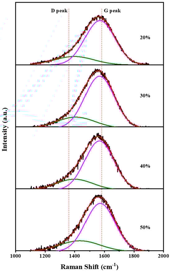
Figure 3.
Raman spectra of ta-C film on silicon chip in 300 V negative bias.
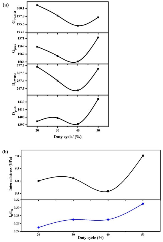
Figure 4.
The peak positions and FWHM of the D and G peaks (a) and residual stress and ID/IG (b) of ta-C films deposited in different duty cycles.
In this study, we investigated the optical properties of the DLC film, with a focus on its optical band gap. In DLC films, the four valence electrons of sp³ hybridized carbon atoms form strong σ bonds, serving as the backbone of the spatial network structure. This strong bonding results in a large optical band gap, making it difficult for photons to be absorbed. Conversely, sp² hybridized carbon atoms only use three valence electrons to form σ bonds, with the remaining electron forming a weak π bond oriented normal to the σ bond plane. This configuration leads to a smaller optical band gap and, thus, easier photon absorption [20]. A wider band gap corresponds to a decreased presence of sp² hybridized carbon [21]. Figure 5 illustrates the Tauc plot derived from UV-Vis spectrophotometric analysis of the absorbance of the ta-C film. Utilizing the established Tauc relation, the optical gap was determined by extrapolating the linear trend of (αhν)1/2 versus photon energy hν, as depicted in Figure 5 [6,7,22]. The obtained Tauc band gap for the prepared amorphous diamond film was 3.12 eV. J. Robertson’s research [23] revealed that an amorphous diamond film exhibiting an optical band gap of 3.12 eV contains a high concentration of sp3 bonds, exceeding 80%. Our finding indicates that the amorphous diamond film synthesized in this study comprises a significant proportion of sp3 hybridized carbon atoms, contributing to its broadened optical band gap. This elevated sp3 content underscores the promising potential of this film for applications demanding exceptional hardness, wear resistance, and optical clarity.
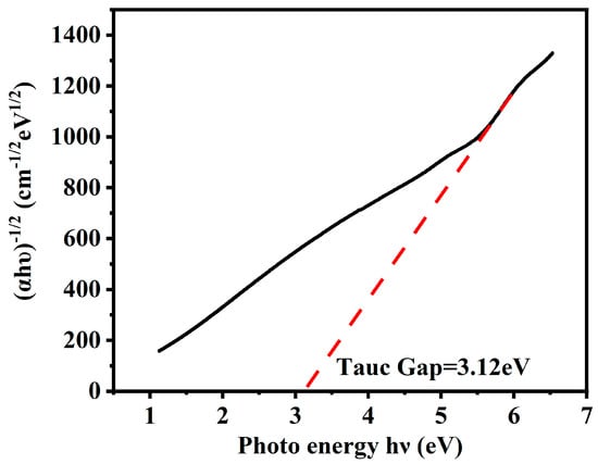
Figure 5.
The Tauc curve of the DLC film prepared with a substrate bias of −300 V and a duty cycle of 20% on a quartz crystal substrate at room temperature.
3.3. Properties of the Ultra-Thick ta-C Film
In light of the above research, a negative bias of 300 V and a duty cycle of 20% were ultimately selected as the parameters for fabricating ultra-thick ta-C films at the micron scale. It was anticipated that these parameters would not only effectively control the residual stress of the film, allowing it to achieve micron-level thickness, but also result in excellent performance. As shown in Figure 6, these parameters successfully yielded ultra-thick DLC films onto a DC53 die steel substrate. The film shows a thickness of 14 μm, exhibiting a uniform, fine, and dense microstructure. No cracks, voids, or detachments were observed within the ta-C layer or at the interface with the substrate, indicating excellent adhesion. By calculating the deposition duration and the achieved film thickness, the average deposition rate was calculated to be 1.4 μm/h.
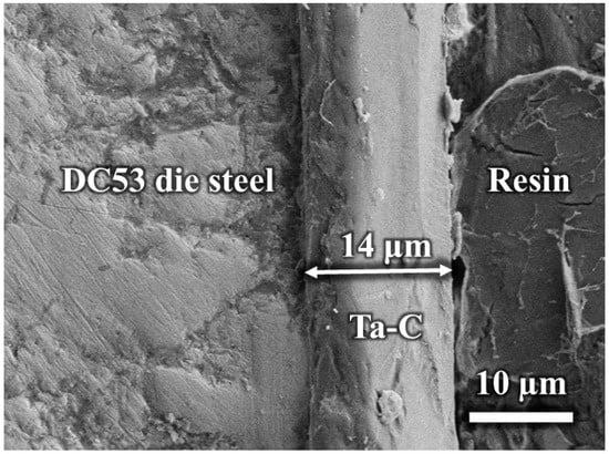
Figure 6.
Cross-sectional picture of the ultra-thick ta-C film prepared under a negative bias of 300 V and a duty cycle of 20% on a DC53 die steel substrate.
The fabricated ta-C thick film exhibited a Vickers hardness of 9415 HV, which is close to that of diamond films and superior to the hardness reported of most ta-C films in the literature [3,12,14,18,24]. This indicates a high sp³ content in the film, contributing to its excellent mechanical properties. Additionally, the fracture toughness of the ta-C thick film was evaluated to be 4 MPa·m1/2 using Equation (3), which is superior to that of natural diamond (3.4 MPa·m1/2) and slightly higher than those of most reported ta-C films [18,25]. These results highlight the potential of the ta-C thick film for applications requiring both high hardness and moderate fracture toughness, demonstrating its ability to achieve diamond-like performance while maintaining mechanical resilience.
The average friction coefficient of the film, measured using a tribometer, was found to be 0.0898, as shown in Figure 7, which is comparable to values reported for ta-C films in the literature [3,26,27]. Initially, the friction coefficient was relatively high and unstable. However, it decreased and stabilized in the later stages of the test. This suggests that the actual friction coefficient of the film may be lower than the average value. Given these outstanding properties, the ta-C thick film is well-suited for use as a coating on die steel and tool steel, enhancing wear resistance and extending the service life of the dies and tools.
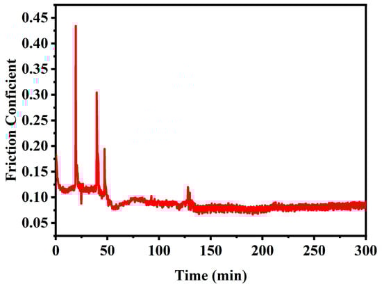
Figure 7.
The friction coefficient of the thick film on DC53 die steel as a function of time.
Because of the high hardness and thickness of the ta-C film, it was challenging to penetrate the film using a scratch tester, which could also lead to the dulling of the diamond tip and potential damage to the indenter. Therefore, the adhesion strength between the film and the substrate was evaluated using a Rockwell hardness tester. Figure 8a shows the Rockwell hardness indentation left on the surface of a sample with a 14 µm thick ta-C film. The Rockwell indentation appeared as a circular pit, within which some localized film detachment occurs. However, no cracks or delamination were observed at the boundary of the indentation, indicating strong adhesion of the film at the edges. This observation highlights the exceptional bonding between the ta-C film and the DC53 die steel substrate. Rockwell hardness testing was also conducted on the side of the sample. Figure 8b presents the morphology of the film surface after testing, revealing that the film remained intact and slightly raised, with no visible cracks. These observations indicate that the fabricated ta-C thick film possessed a certain degree of toughness and demonstrated excellent adhesion to the DC53 die steel.
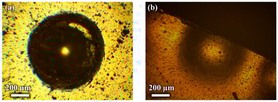
Figure 8.
Rockwell hardness indentation on a 14 µm thick ta-C film deposited on DC53 die steel substrate: (a) Indentation mark on the film surface; (b) morphology of the film surface after indentation on the side of the sample.
4. Conclusions
A high-performance ultra-thick ta-C film was successfully produced by fine-tuning the deposition parameters. The process involved applying a substrate negative bias of 300 V, maintaining a duty cycle of 20%. This approach resulted in a ta-C film with a maximum thickness of 14 µm, characterized by a uniform and refined microstructure. The film exhibited a Vickers hardness of 9415 HV, a fracture toughness of 4 MPa·m1/2, and a low friction coefficient of 0.0898. Furthermore, the adhesion between the ta-C thick film and DC53 die steel was found to be excellent, as indicated by Rockwell hardness indentation tests that revealed no visible changes or damage around the indentations. These findings suggest that the optimized ta-C film demonstrates remarkable hardness, toughness, and adhesion, rendering it highly suitable as a protective coating for cutting tools.
Author Contributions
Conceptualization, X.Z.; methodology, P.P.; software, B.L.; investigation, L.C.; resources, Y.Z.; writing—original draft preparation, review, and editing Q.H.; funding acquisition, X.J. All authors have read and agreed to the published version of the manuscript.
Funding
This project is supported by the 2025 Reform and Development Project and Innovation Engineering Project of BJAST and the 2024 Reform and Development Project of BJAST (24CB007-01).
Institutional Review Board Statement
Not applicable.
Informed Consent Statement
Not applicable.
Data Availability Statement
The data presented in this study are available on request from the corresponding author.
Conflicts of Interest
The authors declare no conflicts of interest. The funders had no role in the design of the study; in the collection, analyses, or interpretation of data; in the writing of the manuscript; or in the decision to publish the results.
References
- Zeng, A.; Neto, V.F.; Gracio, J.J.; Fan, Q.H. Diamond-like carbon (DLC) films as electrochemical electrodes. Diam. Relat. Mater. 2014, 43, 12–22. [Google Scholar] [CrossRef]
- Sheeja, D.; Tay, B.; Lau, S.; Shi, X.; Shi, J.; Li, Y.; Ding, X.; Liu, E.; Sun, Z. Characterization of ta-C films prepared by a two-step filtered vacuum arc deposition technique. Surf. Coatings Technol. 2000, 127, 247–251. [Google Scholar] [CrossRef]
- Ajay, T.; Mugendiran, V.; Vasumathi, M.; Begum, S.R. Study of machining performance and tribological characteristics of monolayer, compound and bilayer Diamond-Like carbon (DLC) coated HSS drill bits. Mater. Today Proc. 2024. [Google Scholar] [CrossRef]
- Kowalski, S. Influence of diamond-like carbon coatings on the wear of the press joint components. Wear 2021, 486–487, 204076. [Google Scholar] [CrossRef]
- Studenya, Z.; Pokornya, Z.; Dobrockya, D.; Joskaa, Z.; Prochazkaa, J. Tribological Properties of DLC Coating for Parts of Weapons. In Proceedings of the 21st ABAF BRNO 2020 Advanced Batteries, Accumulators and Fuel Cellss: International Conference, ECS Transactions, Brno, Czech Republic, 6–9 September 2020; pp. 297–307. [Google Scholar]
- Xiao, J.; Cao, X.; Jiang, A.; Ma, S.; Wang, Z. Design and preparation of FDLC/Ag/FDLC sandwich films with tunable photoelectric performance. Diam. Relat. Mater. 2020, 106, 107825. [Google Scholar] [CrossRef]
- Coşkun, Ö.D.; Zerrin, T. Optical, structural and bonding properties of diamond-like amorphous carbon films deposited by DC magnetron sputtering. Diam. Relat. Mater. 2015, 56, 29–35. [Google Scholar] [CrossRef]
- Wu, S.; Chen, S.; Zhang, L.; Yin, Z.; Liu, Y.; Qi, Y.; Liao, B.; Zhang, X.; Ouyang, X.; Chen, L.; et al. Study on preparation and anti-sand erosion performance of thick DLC coating combined with FCVA deposition and HVP technology. Vacuum 2024, 229, 113532. [Google Scholar] [CrossRef]
- Ferrari, A.C.; Kleinsorge, B.; Morrison, N.A.; Hart, A.; Stolojan, V.; Robertson, J. Stress reduction and bond stability during thermal annealing of tetrahedral amorphous carbon. J. Appl. Phys. 1999, 85, 7191–7197. [Google Scholar] [CrossRef]
- Donnet, C. Recent progress on the tribology of doped diamond-like and carbon alloy coatings: A review. Surf. Coatings Technol. 1998, 100–101, 180–186. [Google Scholar] [CrossRef]
- Liang, H.; Delian, L.; Xian, C.; Li, Y.; Yuqing, Z. The deposition of a thick tetrahedral amorphous carbon film by argon ion bombardment. Appl. Surf. Sci. 2012, 258, 4794–4800. [Google Scholar] [CrossRef]
- Kennedy, M.; Hoppe, S.; Esser, J. Lower Friction Losses with New Piston Ring Coating. Auto Tech Rev. 2014, 3, 30–35. [Google Scholar] [CrossRef]
- Shen, Y.; Ou, Y.; Wang, H.; Liao, B.; Wu, X.; Zhang, X. Wear and corrosion resistance of diamond-like carbon coatings deposited by filtered cathodic vacuum arc coupled with a high-voltage pulse power. Mater. Res. Express 2019, 6, 105625. [Google Scholar] [CrossRef]
- Shen, Y.; Liao, B.; Zhang, Z.; Wu, X.; Ying, M.; Zhang, X. Anti-sand erosion and tribological performance of thick DLC coatings deposited by the filtered cathodic vacuum arc. Appl. Surf. Sci. 2020, 533, 147371. [Google Scholar] [CrossRef]
- Zhang, H.; Chen, Y.; Liao, B.; Wu, X.; Zhang, H.; Zhang, X. Effect of C2H2 flow rate on microstructure and properties of nc–Cu/a–C:H nanocomposite films prepared by filtered cathodic vaccum arc technique. Nucl. Instrum. Methods Phys. Res. Sect. B Beam Interact. Mater. Atoms 2013, 307, 137–142. [Google Scholar] [CrossRef]
- Majhi, A.; Dilliwar, M.; Pradhan, P.C.; Jena, S.; Nayak, M.; Singh, M.N.; Udupa, D.V.; Sahoo, N.K. Evaluation of microstructure and residual stress in W/B4C multilayer optics. J. Appl. Phys. 2018, 124, 115306. [Google Scholar] [CrossRef]
- Jayanth, H.; Gangadhar, N.; Purushothama, K.M. Insitu Hybrid Composites Reinforced with B4C and Tio2 in an Al7075 Matrix Formed and It’s Mechanical and Wear Properties are Analysed. Power Syst. Technol. 2024, 48, 2109–2130. [Google Scholar] [CrossRef]
- Hainsworth, S.V.; Uhure, N.J. Diamond like carbon coatings for tribology: Production techniques, characterisation methods and applications. Int. Mater. Rev. 2013, 52, 153–174. [Google Scholar] [CrossRef]
- Huang, Q.; Yu, D.; Xu, B.; Hu, W.; Ma, Y.; Wang, Y.; Zhao, Z.; Wen, B.; He, J.; Liu, Z.; et al. Nanotwinned diamond with unprecedented hardness and stability. Nature 2014, 510, 250–253. [Google Scholar] [CrossRef]
- Lu, Y.-M.; Wang, Y.-J.; Xu, M.-M.; Wang, H.; Xi, L. Micro-structural and optical properties of diamond-like carbon films grown by magnetic field-assisted laser deposition. Acta Phys. Sin. 2024, 73, 108101. [Google Scholar] [CrossRef]
- Pandey, B.; Pal, P.; Bera, S.; Ray, S.; Kar, A. Effect of Nickel Incorporation on Microstructural and Optical Properties of Electrodeposited Diamond Like Carbon (DLC) Thin Films. Appl. Surf. Sci. 2012, 261, 789–799. [Google Scholar] [CrossRef]
- Xiao, J.; Xu, H.; Guo, A.; Wang, Y. Study on FN-DLC thinfiIms: (II) effect of radio frequency power on the optical band gap of the thin fiIms. Acta Phys. Sin. 2007, 56, 1809–1814. [Google Scholar] [CrossRef]
- Robertson, J. Diamond-like amorphous carbon. Mater. Sci. Eng. R Rep. 2002, 37, 129–281. [Google Scholar] [CrossRef]
- García, J.A.; Rivero, P.J.; Barba, E.; Fernández, I.; Santiago, J.A.; Palacio, J.F.; Fuente, G.G.; Rodríguez, R.J. A Comparative Study in the Tribological Behavior of DLC Coatings Deposited by HiPIMS Technology with Positive Pulses. Metals 2020, 10, 174. [Google Scholar] [CrossRef]
- Kareem, H.J.; Al-Roubaiy, A.O.; Omidvar, H. Brazing Polycrystalline Diamonds (PCDs) in Applications of Cutting Tools: A review. BIO Web Conf. 2023, 65, 07006. [Google Scholar] [CrossRef]
- Penkov, O.V.; Pukha, V.E.; Zubarev, E.N.; Yoo, S.-S.; Kim, D.-E. Tribological properties of nanostructured DLC coatings deposited by C60 ion beam. Tribol. Int. 2013, 60, 127–135. [Google Scholar] [CrossRef]
- Härtwig, F.; Lorenz, L.; Makowski, S.; Krause, M.; Habenicht, C.; Lasagni, A.F. Low-Friction of ta-C Coatings Paired with Brass and Other Materials under Vacuum and Atmospheric Conditions. Materials 2022, 15, 2534. [Google Scholar] [CrossRef]
Disclaimer/Publisher’s Note: The statements, opinions and data contained in all publications are solely those of the individual author(s) and contributor(s) and not of MDPI and/or the editor(s). MDPI and/or the editor(s) disclaim responsibility for any injury to people or property resulting from any ideas, methods, instructions or products referred to in the content. |
© 2025 by the authors. Licensee MDPI, Basel, Switzerland. This article is an open access article distributed under the terms and conditions of the Creative Commons Attribution (CC BY) license (https://creativecommons.org/licenses/by/4.0/).