
Wire Arc Additive Manufacturing of Scalmalloy® (Al-Mg-Sc-Zr): Thermal Management Effects on Direct Age-Hardening Response

 , and
, and
Abstract
1. Introduction
2. Materials and Methods

3. Results
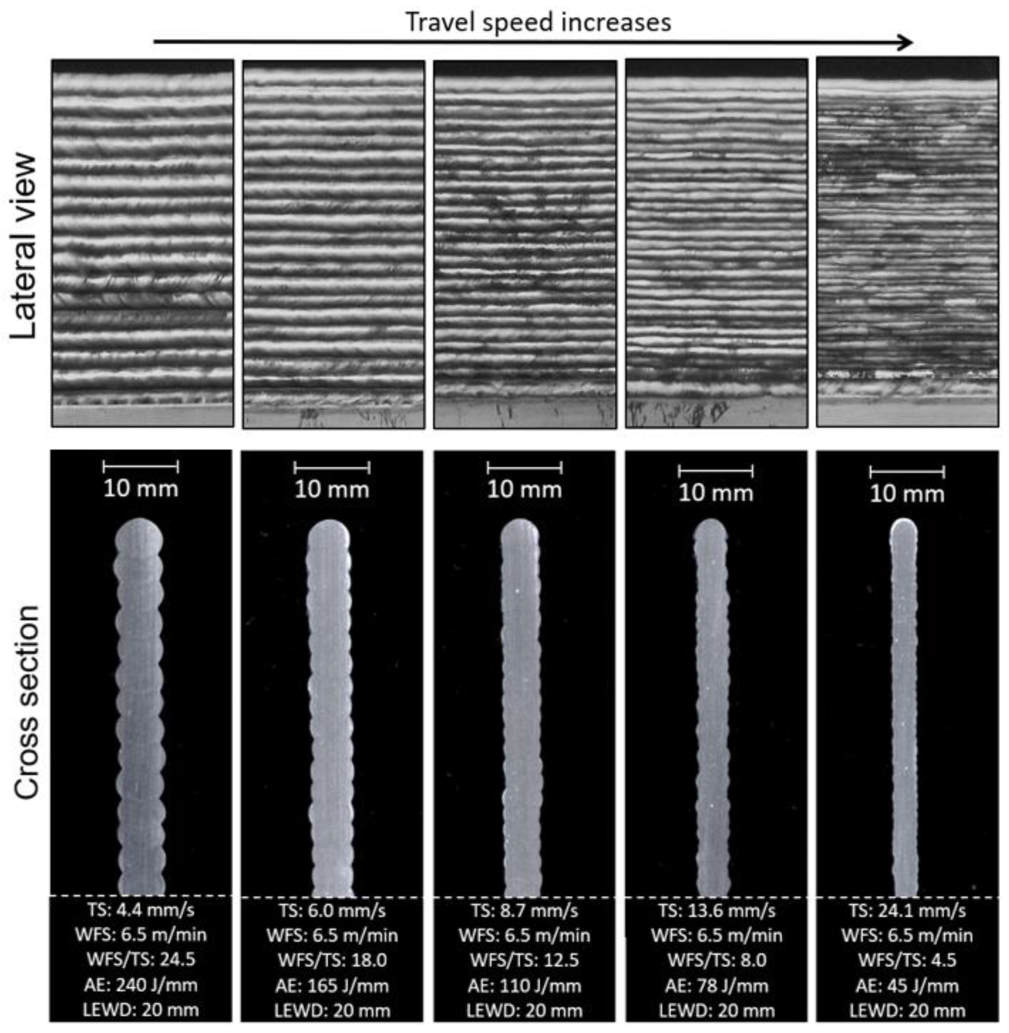
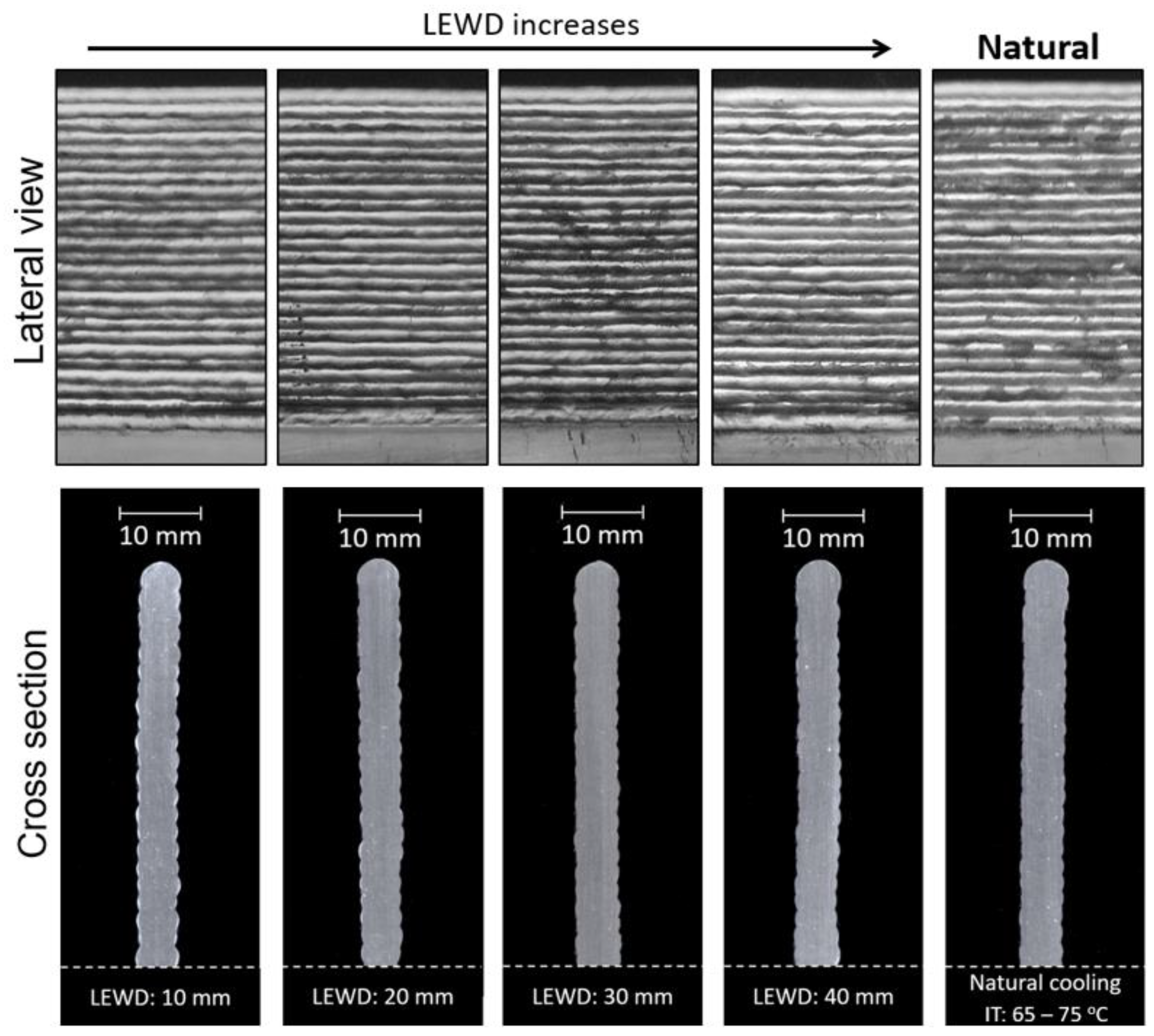
3.1. Results on Geometrical Features, Porosity, and Processing Time
3.2. Results on Thermal Features
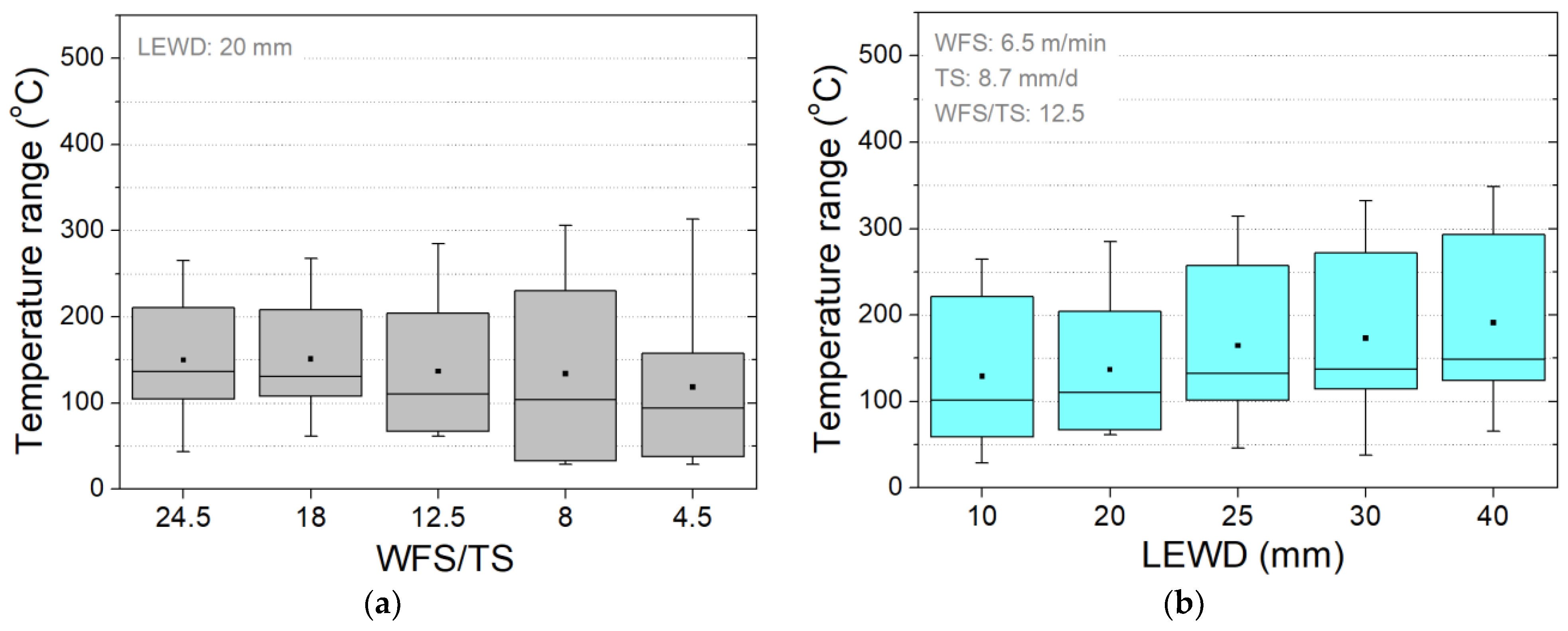
3.2.1. Interpass Temperature Estimation
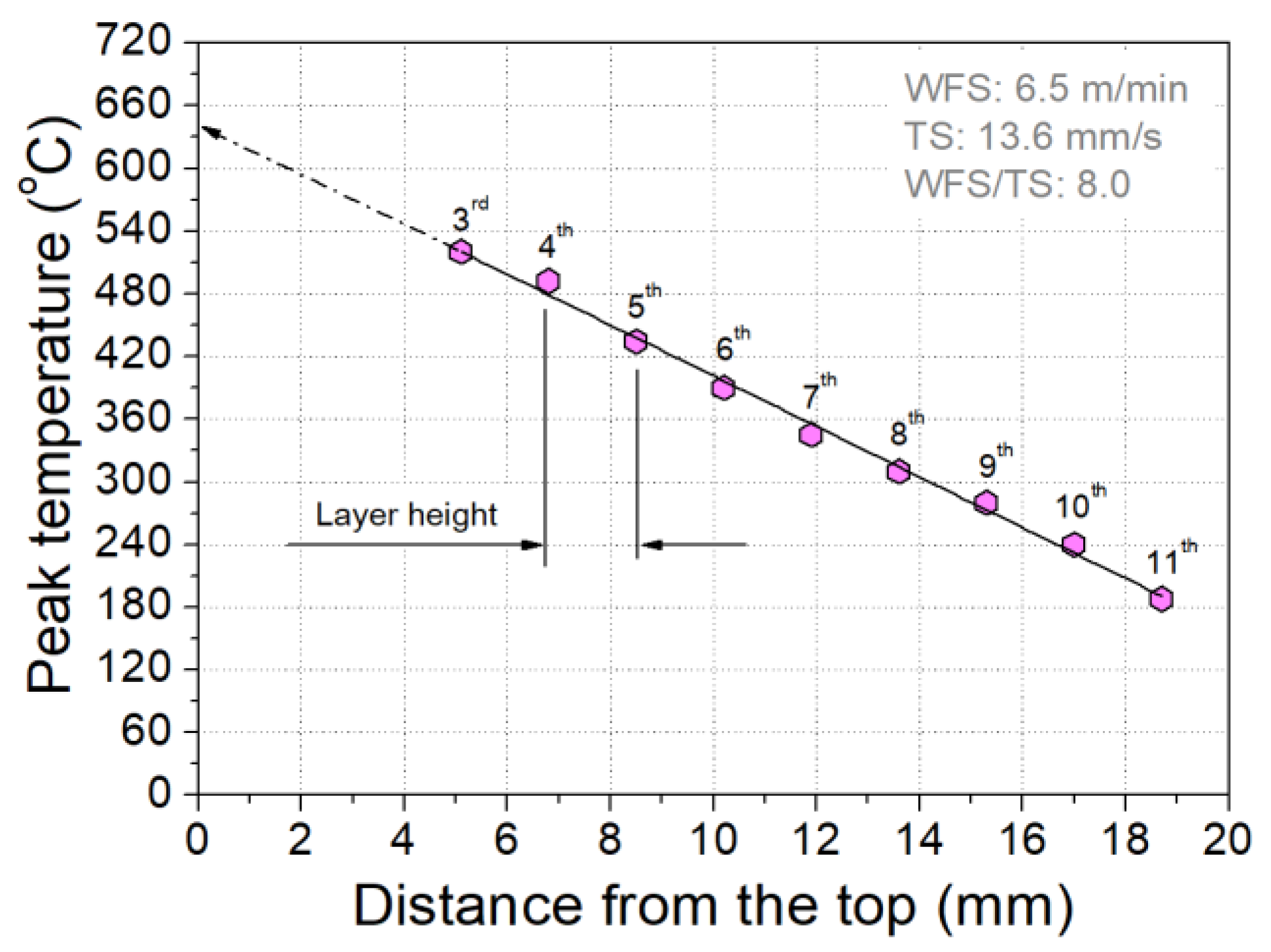
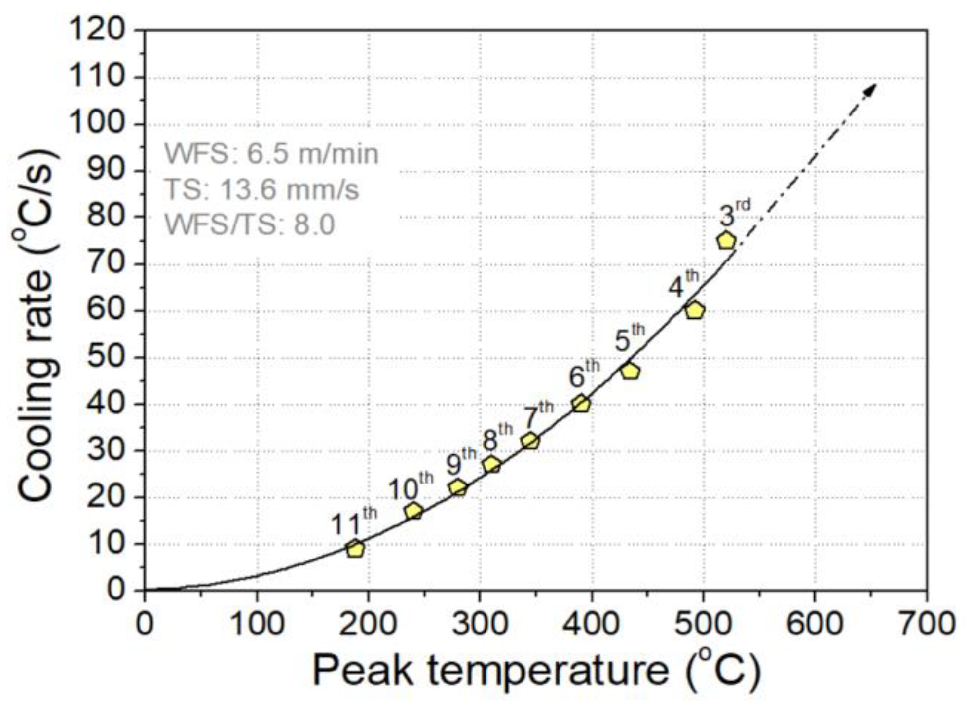
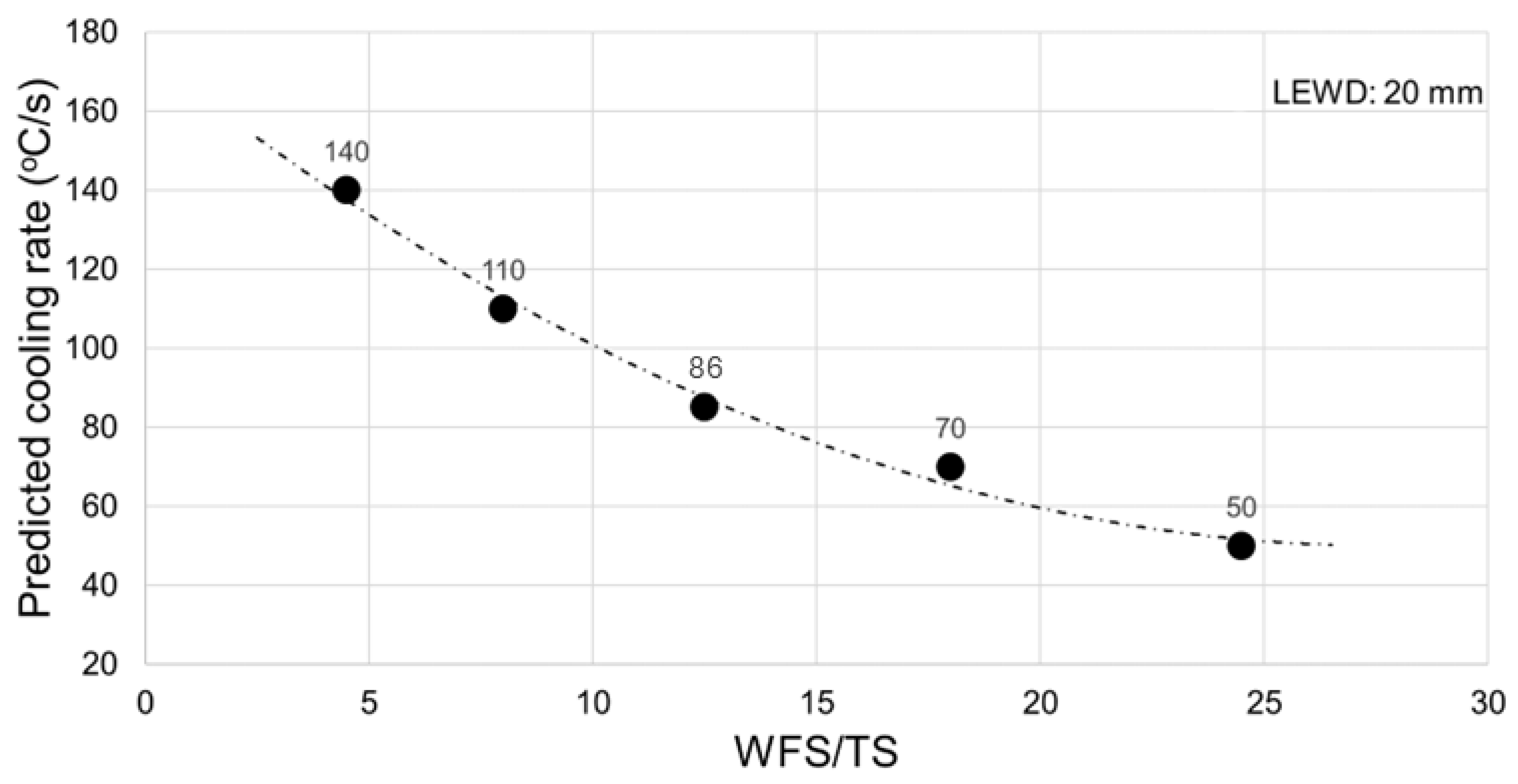
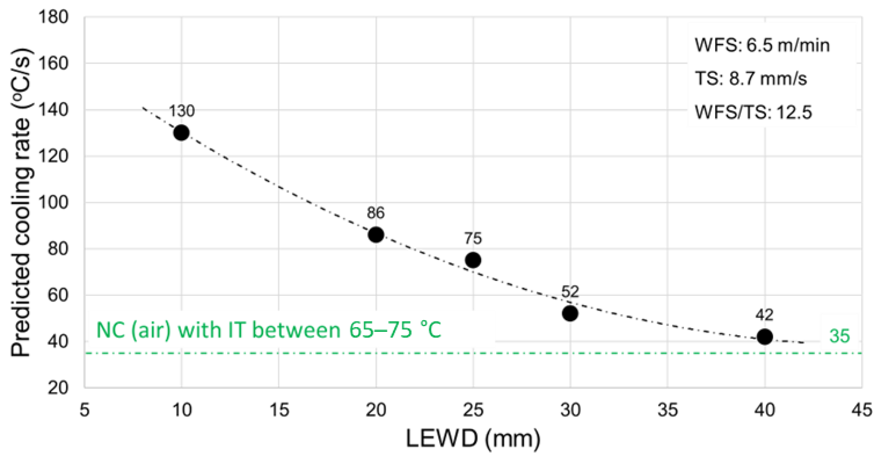
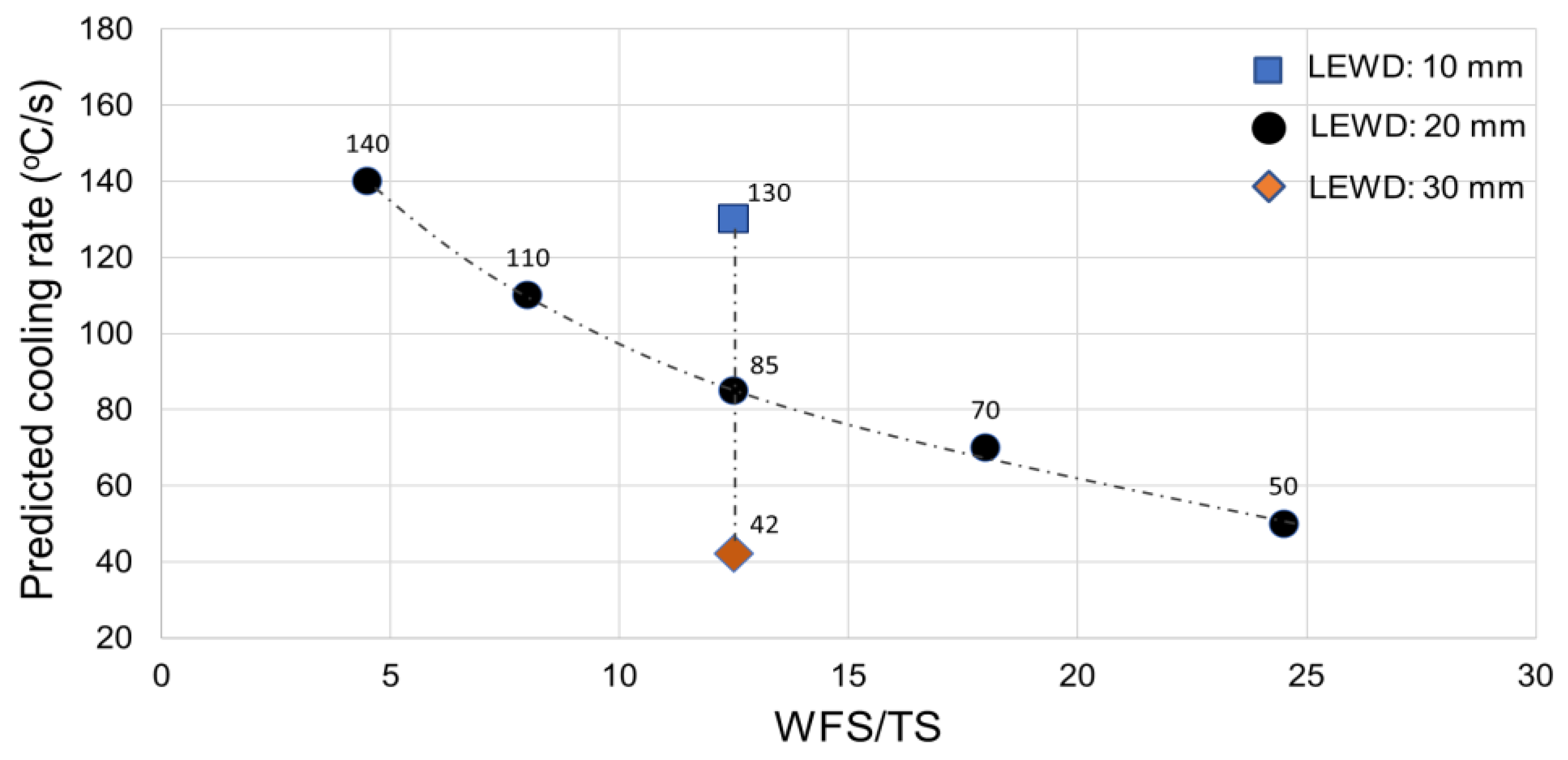
3.2.2. Cooling Rate Estimation
3.2.3. Resultant Cooling Rates
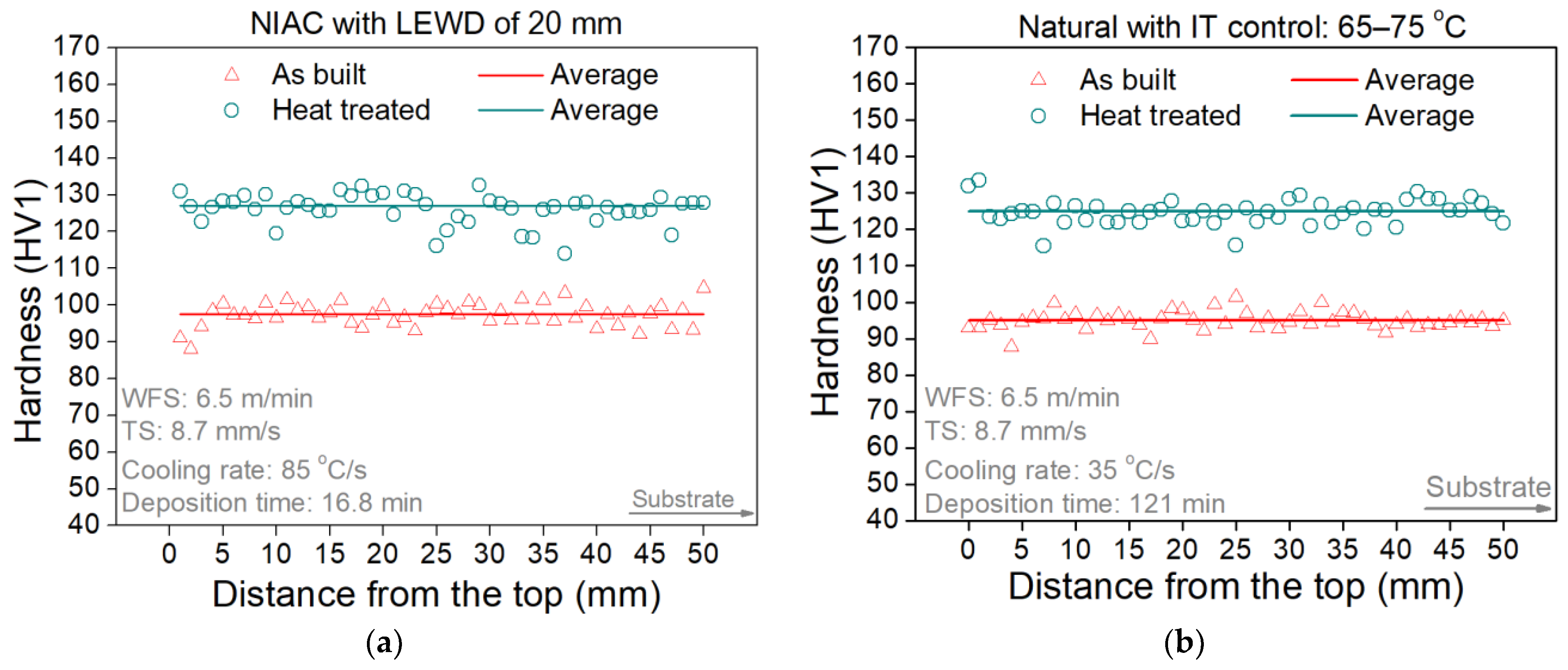
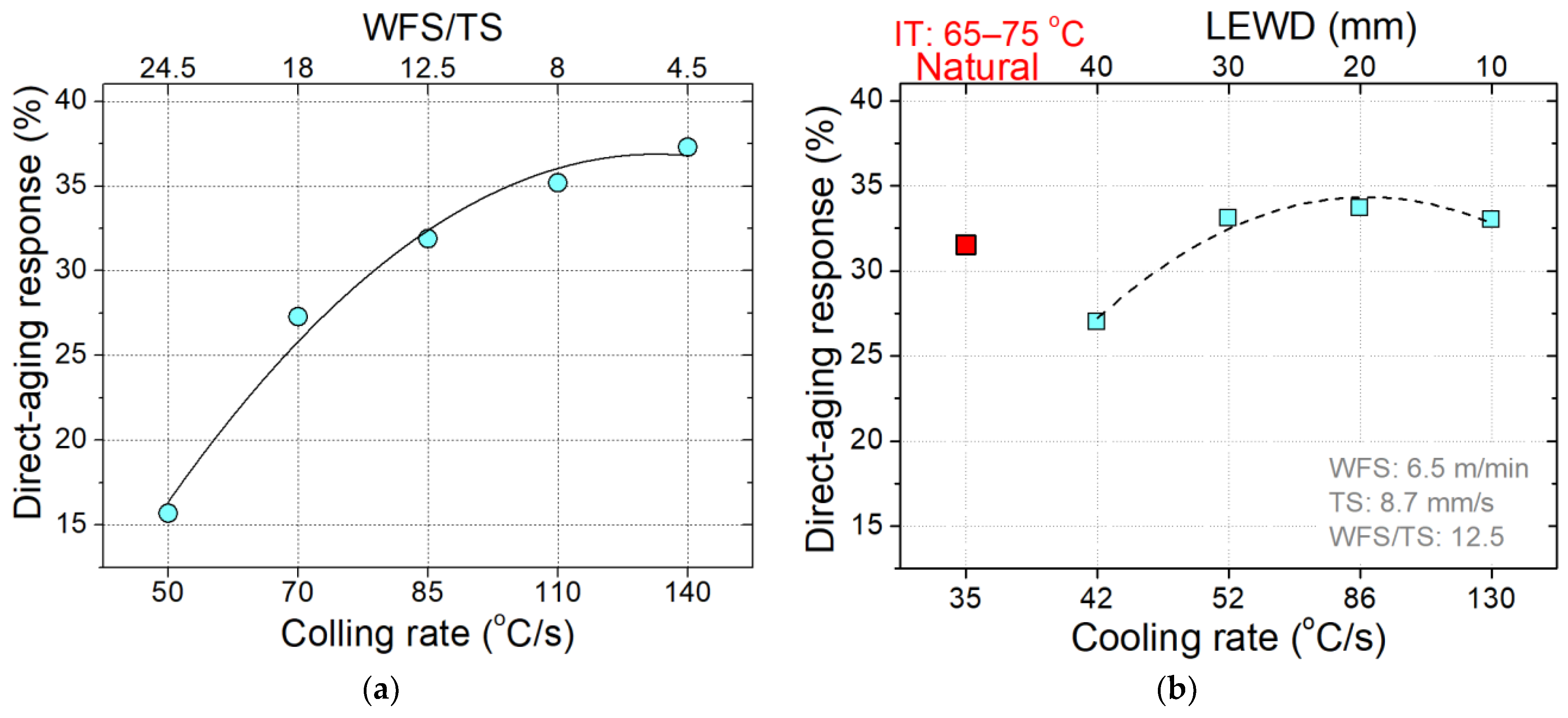
3.3. Results on Direct-Aging Response
4. Discussions
4.1. Discussions on Geometrical Features, Porosity, and Processing Time
4.2. Discussions on Thermal Features
4.3. Discussions on Direct-Aging Response
- (a)
- Variation in the hardness profile along the preform height: If a significant hardness level variation is observed along the preform height, it indicates that primary Al3(Sc,Zr) precipitation may have occurred to a varying extent during deposition due to the thermal history imposed by the WAAM process (the re-heating cycles and possible heat accumulation could change the hardness levels after each layer);
- (b)
- Positive direct-aging response: If the hardness level increases after direct age-hardening, it suggests that Sc may have remained in the supersaturated solid solution during deposition and that secondary Al3(Sc,Zr) precipitation was likely activated by the post-WAAM heat treatment. In this case, the direct-aging response result should be proportional, among other factors, to the fraction of Sc that remained in the supersaturated solid solution;
- (c)
- No direct-aging response: If the hardness level remains largely unchanged after the post-WAAM heat treatment, it indicates that the part may have been already exposed to overaging in the as-built state and therefore could not respond to the direct age-hardening procedure applied;
- (d)
- Negative direct-aging response: If the hardness level decreases after direct age-hardening, it implies that primary Al3(Sc,Zr) precipitation may have extensively occurred during the sequential depositions (likely not leaving any significant Sc content in the supersaturated solid solution), which could be driven to overaging by the post-WAAM heat treatment.
4.4. Industrial Impact and Practical Applications
5. Conclusions
- ➣
- The geometrical aspect of the parts was positive and similar despite the changes in thermal management, with the surface waviness ranging from 0.15 to 0.5 mm;
- ➣
- The porosity of the parts was not an issue and similar despite the changes in thermal management, with the relative density ranging from 96.1 to 98.5% (considering the Scalmalloy® feedstock material fully dense as reference);
- ➣
- The WAAM processing time could be reduced down to 16.8 min with the application of the NIAC technique against 121 min needed with the NC approach (an impressive 86% reduction);
- ➣
- The response to direct age-hardening was always positive, with the highest level of increase in hardness at 34% as a consequence of the fast cooling rates provided by the intrinsic (arc energy selection) and active (NIAC technique application) thermal management solution employed.
Author Contributions
Funding
Institutional Review Board Statement
Informed Consent Statement
Data Availability Statement
Acknowledgments
Conflicts of Interest
Abbreviations
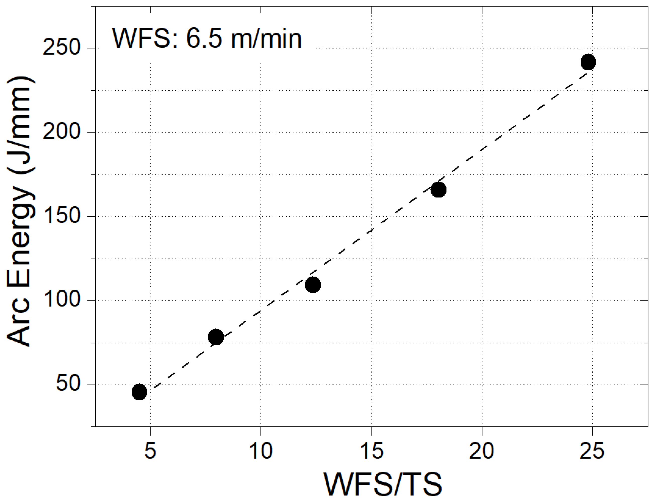
| AE | Arc energy per unit length of deposit |
| CMT | Cold metal transfer |
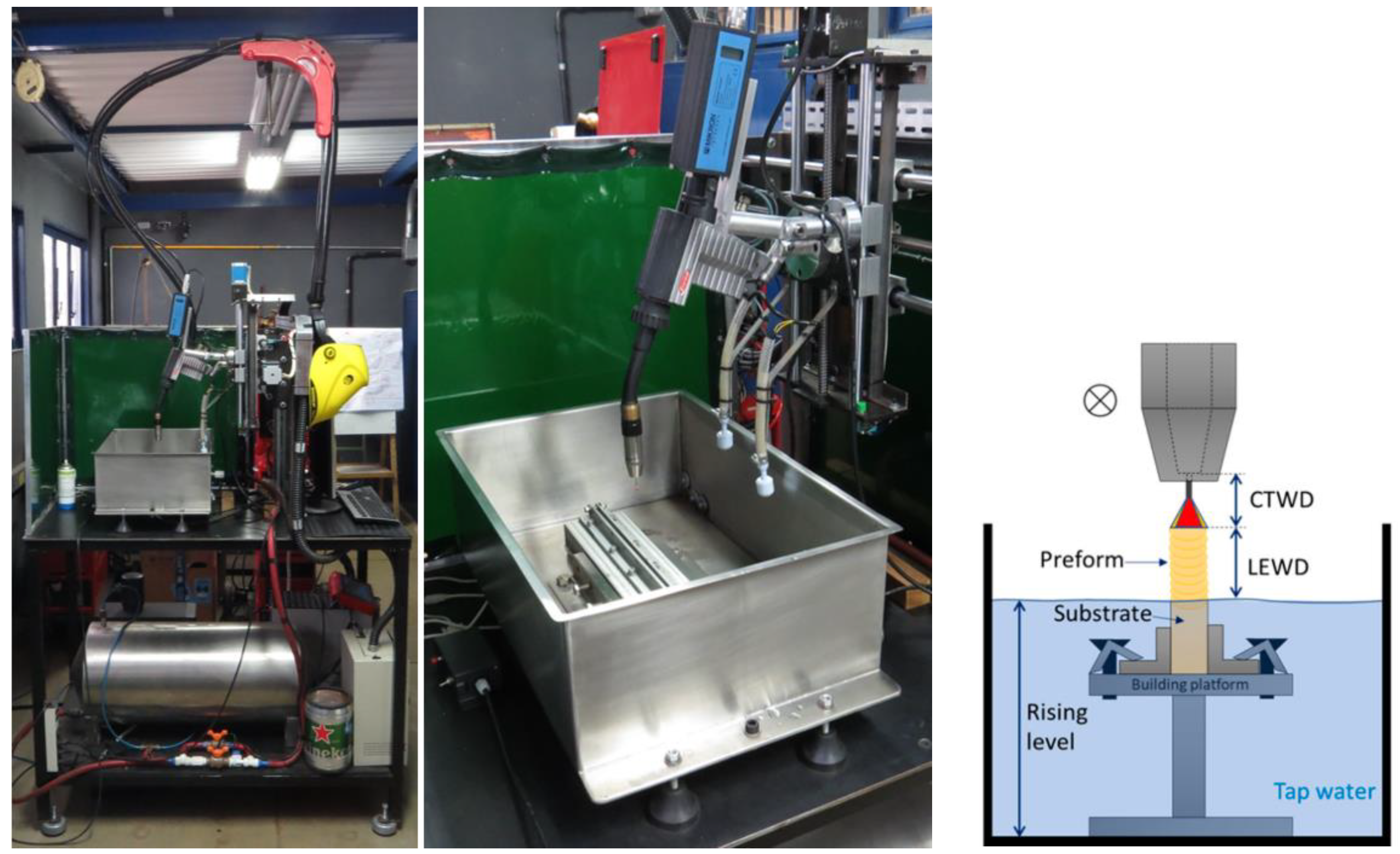
| CTWD | Contact tube to work distance |
| DAR | Direct-aging response |
| DED | Directed energy deposition |
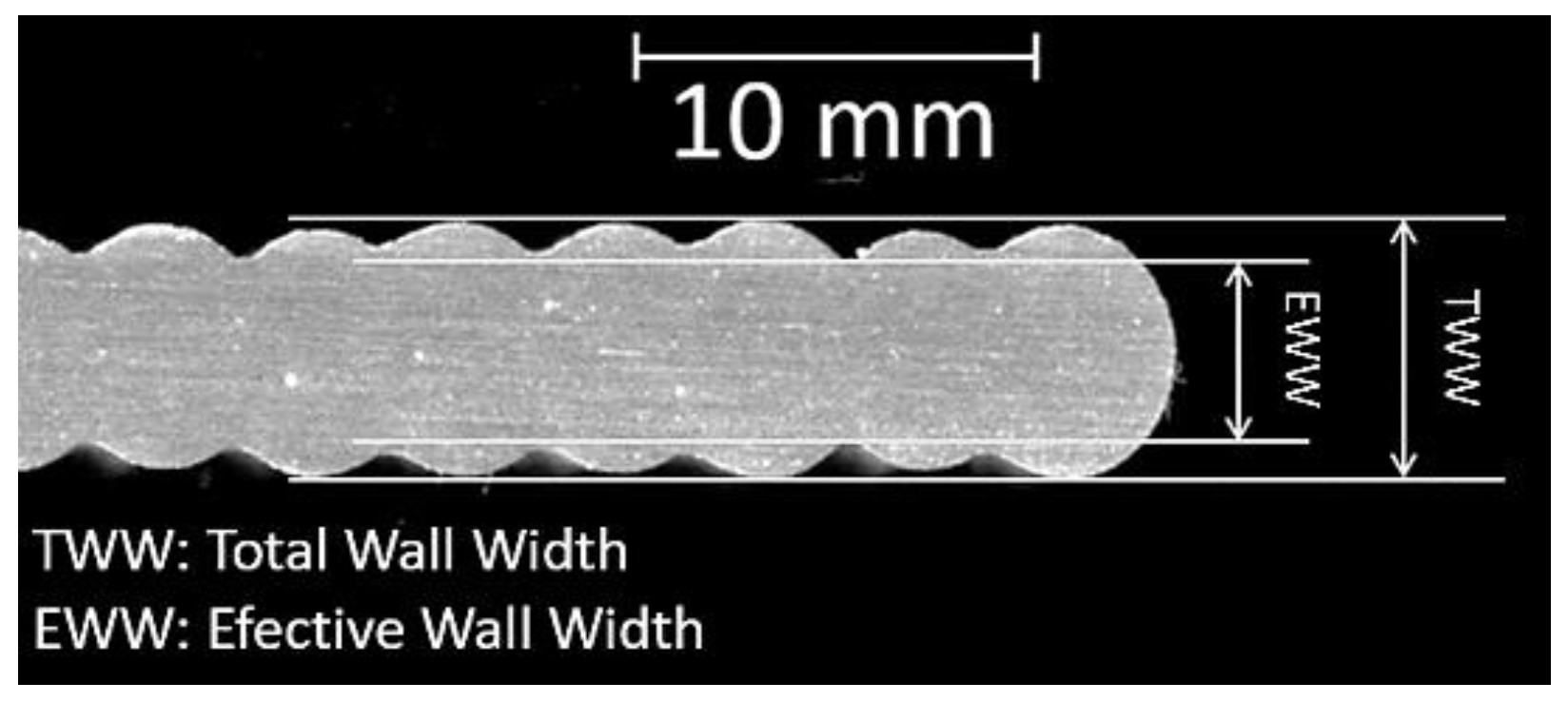
| EWW | Effective wall width |
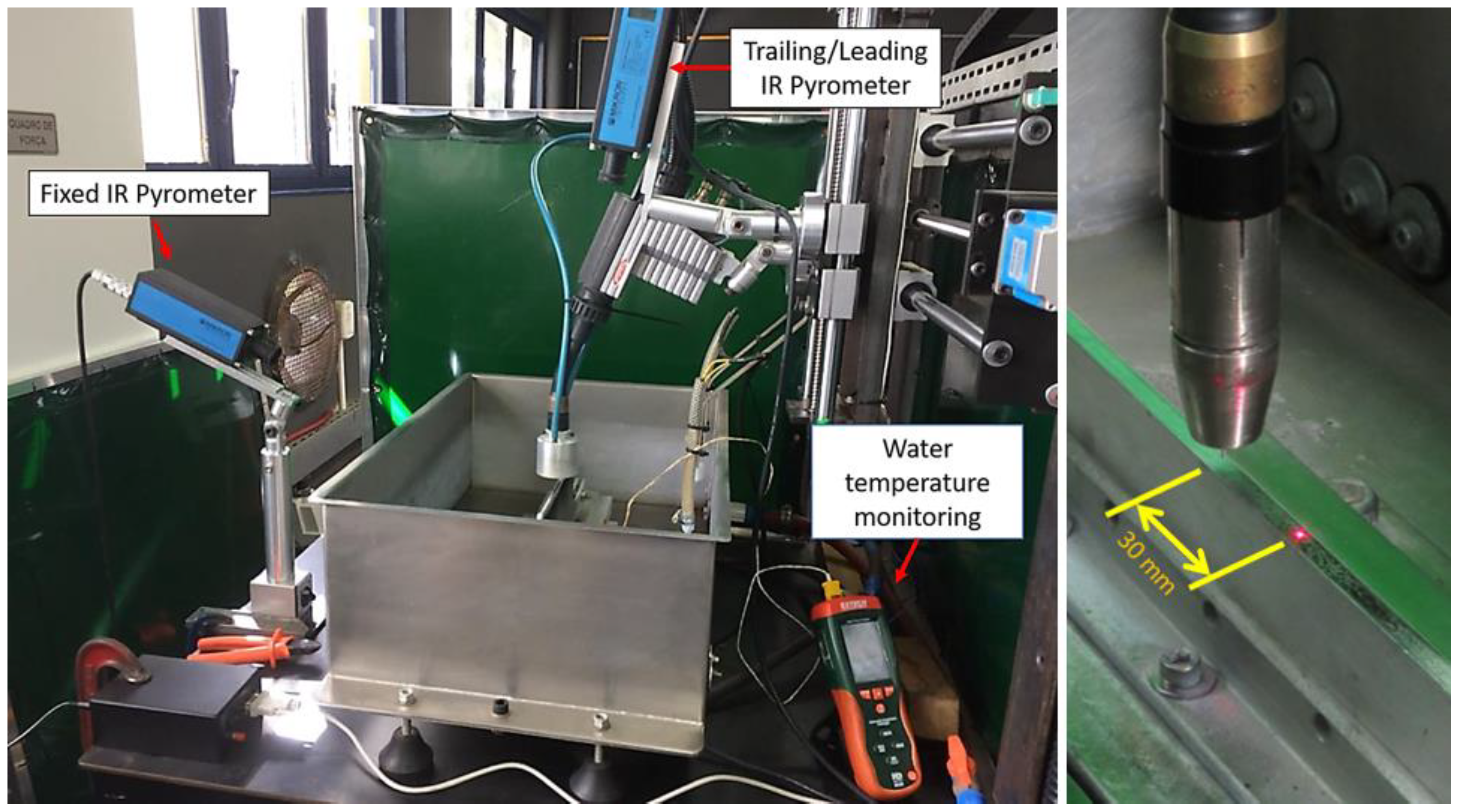
| IR | Infrared |
| IT | Interpass temperature |
| LEWD | Layer edge to water distance |
| LT | Layer thickness |
| NC | Natural cooling |
| NIAC | Near-immersion active cooling |
| NL | Number of layers |
| PT | Processing time |
| SW | Surface waviness |
| TS | Travel speed |
| TWW | Total wall width |
| WAAM | Wire arc additive manufacturing |
| WFS | Wire feed speed |
References
- Røyset, J.; Ryum, N. Scandium in Aluminium Alloys. Int. Mater. Rev. 2005, 50, 19–44. [Google Scholar] [CrossRef]
- Spierings, A.B.; Dawson, K.; Kern, K.; Palm, F.; Wegener, K. SLM-Processed Sc- and Zr-Modified Al-Mg Alloy: Mechanical Properties and Microstructural Effects of Heat Treatment. Mater. Sci. Eng. A 2017, 701, 264–273. [Google Scholar] [CrossRef]
- Kürnsteiner, P.; Bajaj, P.; Gupta, A.; Wilms, M.B.; Weisheit, A.; Li, X.; Leinenbach, C.; Gault, B.; Jägle, E.A.; Raabe, D. Control of Thermally Stable Core-Shell Nano-Precipitates in Additively Manufactured Al-Sc-Zr Alloys. Addit. Manuf. 2020, 32, 100910. [Google Scholar] [CrossRef]
- Wang, Z.; Lin, X.; Kang, N.; Chen, J.; Tang, Y.; Tan, H.; Yu, X.; Yang, H.; Huang, W. Directed Energy Deposition Additive Manufacturing of a Sc/Zr-Modified Al–Mg Alloy: Effect of Thermal History on Microstructural Evolution and Mechanical Properties. Mater. Sci. Eng. A 2021, 802, 140606. [Google Scholar] [CrossRef]
- Reis, R.P.; da Silva, L.J. Thermal Management Approaches for Arc Additive Manufacturing: A Comprehensive Review over a Decade of Developments and Applications. Int. J. Adv. Manuf. Technol. 2025, 136, 1805–1931. [Google Scholar] [CrossRef]
- e Silva, R.H.G.; Rocha, P.C.J.; Rodrigues, M.B.; Pereira, M.; Galeazzi, D. Analysis of Interlayer Idle Time as a Temperature Control Technique in Additive Manufacturing of Thick Walls by Means of CMT and CMT Pulse Welding Processes. Soldag. Insp. 2020, 25, e2501. [Google Scholar] [CrossRef]
- Zheng, Y.; Yu, Z.; Xie, J.; Chen, J.; Yu, C.; Xu, J.; Lu, H. A Numerical Model-Based Deposition Strategy for Heat Input Regulation during Plasma Arc-Based Additive Manufacturing. Addit. Manuf. 2022, 58, 102986. [Google Scholar] [CrossRef]
- Lu, X.; Zhou, Y.F.; Xing, X.L.; Shao, L.Y.; Yang, Q.X.; Gao, S.Y. Open-Source Wire and Arc Additive Manufacturing System: Formability, Microstructures, and Mechanical Properties. Int. J. Adv. Manuf. Technol. 2017, 93, 2145–2154. [Google Scholar] [CrossRef]
- Reisgen, U.; Sharma, R.; Mann, S.; Oster, L. Increasing the Manufacturing Efficiency of WAAM by Advanced Cooling Strategies. Weld. World 2020, 64, 1409–1416. [Google Scholar] [CrossRef]
- da Silva, L.J.; Ferraresi, H.N.; Araújo, D.B.; Reis, R.P.; Scotti, A. Effect of Thermal Management Approaches on Geometry and Productivity of Thin-Walled Structures of ER 5356 Built by Wire + Arc Additive Manufacturing. Coatings 2021, 11, 1141. [Google Scholar] [CrossRef]
- Hou, X.; Zhao, L.; Ren, S.; Peng, Y.; Ma, C.; Tian, Z.; Qu, X. A Comparative Study on Al-Mg-Sc-Zr Alloy Fabricated by Wire Arc Additive Manufacturing with Controlling Interlayer Temperature and Continuous Printing: Porosity, Microstructure, and Mechanical Properties. J. Mater. Sci. Technol. 2024, 193, 199–216. [Google Scholar] [CrossRef]
- Ponomareva, T.; Ponomarev, M.; Kisarev, A.; Ivanov, M. Wire Arc Additive Manufacturing of Al-Mg Alloy with the Addition of Scandium and Zirconium. Materials 2021, 14, 3665. [Google Scholar] [CrossRef] [PubMed]
- Xia, Y.; Cai, X.; Dong, B.; Lin, S. Wire Arc Additive Manufacturing of Al-Mg-Sc Alloy: An Analysis of the Effect of Sc on Microstructure and Mechanical Properties. Mater. Charact. 2023, 203, 113116. [Google Scholar] [CrossRef]
- Rometsch, P.A.; Zhong, H.; Nairn, K.M.; Wu, X. Characterization of a Laser-Fabricated Hypereutectic Al—Sc Alloy Bar. Scr. Mater. 2014, 87, 13–16. [Google Scholar] [CrossRef]
- da Silva, L.J.; Souza, D.M.; de Araújo, D.B.; Reis, R.P.; Scotti, A. Concept and Validation of an Active Cooling Technique to Mitigate Heat Accumulation in WAAM. Int. J. Adv. Manuf. Technol. 2020, 107, 2513–2523. [Google Scholar] [CrossRef]
- da Silva, L.J.; Teixeira, F.R.; Araújo, D.B.; Reis, R.P.; Scotti, A. Work Envelope Expansion and Parametric Optimization in Waam with Relative Density and Surface Aspect as Quality Constraints: The Case of Al5mg Thin Walls with Active Cooling. J. Manuf. Mater. Process. 2021, 5, 40. [Google Scholar] [CrossRef]
- Kuo, C.N.; Peng, P.C.; Liu, D.H.; Chao, C.Y. Microstructure Evolution and Mechanical Property Response of 3d-Printed Scalmalloy with Different Heat-Treatment Times at 325 °C. Metals 2021, 11, 555. [Google Scholar] [CrossRef]
- Wang, Y.; Li, J.; Xia, X.; Zou, L.; Yuan, T.; Liu, X.; Lai, D.; Deng, S.; Li, R. A Novel Al-Cr-Sc-Zr Alloy Additively Manufactured via Laser Directed Energy Deposition: Microstructure, Phase Analysis and Mechanical Properties. J. Mater. Process. Technol. 2023, 322, 118204. [Google Scholar] [CrossRef]
- Taendl, J.; Orthacker, A.; Amenitsch, H.; Kothleitner, G.; Poletti, C. Influence of the Degree of Scandium Supersaturation on the Precipitation Kinetics of Rapidly Solidified Al-Mg-Sc-Zr Alloys. Acta Mater. 2016, 117, 43–50. [Google Scholar] [CrossRef]
- Gierth, M.; Henckell, P.; Ali, Y.; Scholl, J.; Bergmann, J.P. Wire Arc Additive Manufacturing (WAAM) of Aluminum Alloy AlMg5Mn with Energy-Reduced Gas Metal Arc Welding (GMAW). Materials 2020, 13, 2671. [Google Scholar] [CrossRef]
- TWI. Which Is Important—Preheat or Interpass? Available online: https://www.twi-global.com/technical-knowledge/faqs/faq-which-is-important-preheat-or-interpass (accessed on 22 November 2024).
- Ren, L.; Gu, H.; Wang, W.; Wang, S.; Li, C.; Wang, Z.; Zhai, Y.; Ma, P. Effect of Sc Content on the Microstructure and Properties of Al–Mg–Sc Alloys Deposited by Wire Arc Additive Manufacturing. Met. Mater. Int. 2020, 27, 68–77. [Google Scholar] [CrossRef]
- Lohar, A.K.; Mondal, B.N.; Panigrahi, S.C. Influence of Cooling Rate on the Microstructure and Ageing Behavior of As-Cast Al–Sc–Zr Alloy. J. Mater. Process. Technol. 2010, 210, 2135–2141. [Google Scholar] [CrossRef]
- Shi, Y.; Yang, K.; Kairy, S.K.; Palm, F.; Wu, X.; Rometsch, P.A. Effect of Platform Temperature on the Porosity, Microstructure and Mechanical Properties of an Al—Mg—Sc—Zr Alloy Fabricated by Selective Laser Melting. Mater. Sci. Eng. A 2018, 732, 41–52. [Google Scholar] [CrossRef]


| TM | Natural | Intrinsic (process-based) | Passive | Active |
| Concepts [5] | Relies on convection, conduction, and radiation for heat dissipation, with cooling times between layers during fabrication | Adjusts deposition parameters (such as power, wire/powder feed rate, and travel speed) and/or deposition path to control heat input during fabrication | Acts over the substrate and/or building platform to modify heat dissipation from the parts via conduction during fabrication | Applies direct means to the parts, such as by liquids/gasses, for more efficient temperature control during fabrication |
| Examples | Silva et al. [6] controlled the interpass temperature by the cooling time between the layers during WAAM of parts made from an ER309LSi wire | Zheng at al. [7] controlled the heat input in PTA 1-DED parts made from Inconel 625 powder, improving geometrical accuracy and reducing deposition time and energy consumption | Lu at al. [8] used a water-cooled building platform to avoid heat accumulation and improve geometrical quality in WAAM from an ER70s-6 wire | Reisgen et al. [9] applied water bath and water aerosol to cool thin-walled structures produced by WAAM from an ER70s-6 wire |
| Arc AM equipment | Fronius CMT 1—TransPuls Synergic 5000 |
| Synergic line code | CMT 1070 |
| Shielding gas | Commercially pure Ar at 12 L/min |
| Wire | Scalmalloy® with 1.0 mm in diameter |
| Substrate | Al5052 (280 mm × 38.1 mm × 6.35 mm) |
| CTWD 2 | 12 mm |
| Preform geometry | Thin walls with 50 mm in height 3 and 250 mm in length |
| Building strategy | Single-pass multi-layer bidirectional depositions |
| Cooling liquid for NIAC | Tap water (20–30 °C) |
| Dwell time for NIAC | 5 s after/before each layer 4 |
| Run | WFS (m/min) | TS (mm/s) | WFS/TS | Z Increment (mm) | LEWD (mm) |
|---|---|---|---|---|---|
| 1 | 6.5 | 4.4 | 24.5 | 3.2 | 20 |
| 2 | 6.0 | 18.0 | 2.7 | ||
| 3 | 8.7 | 12.5 | 2.2 | ||
| 4 | 13.6 | 8.0 | 1.6 | ||
| 5 | 24.1 | 4.5 | 1.4 |
| Run | WFS (m/min) | TS (mm/s) | WFS/TS | Z Increment (mm) | LEWD (mm) |
|---|---|---|---|---|---|
| 6 | 6.5 | 8.7 | 12.5 | 2.2 | 10 |
| 7 1 | 20 | ||||
| 8 | 30 | ||||
| 9 | 40 | ||||
| 10 | NC 2 |
| Wire Spool | Mg | Sc | Zr | Ti | Al |
|---|---|---|---|---|---|
| 1 | 4.68 | 0.42 | 0.086 | 0.13 | Balance |
| 2 | 4.64 | 0.44 | 0.095 | 0.15 | Balance |
| IR pyrometers | Mikron MI-PE140 with focusable optics |
| Spectral range | 3–5 μm |
| Temperature range | 30–1000 °C |
| Spot size | Ø of 2.9 mm at a distance of 380 mm |
| Emissivity | 22% |
| Resolution | 0.1 °C |
| WFS/TS | TWW (mm) | EWW (mm) | SW (mm) | LT (mm) | RD (%) | PT (min) | NL |
|---|---|---|---|---|---|---|---|
| 24.5 | 6.6 | 5.6 | 0.5 | 3.5 | 98.4 | 18.8 | 16 |
| 18.0 | 5.9 | 5.3 | 0.3 | 2.8 | 98.3 | 18.4 | 20 |
| 12.5 | 5.3 | 4.9 | 0.2 | 2.2 | 98.5 | 16.8 | 24 |
| 8.0 | 4.8 | 4.0 | 0.4 | 1.7 | 98.0 | 15.5 | 30 |
| 4.5 | 3.5 | 3.2 | 0.15 | 1.2 | 97.1 | 14.9 | 44 |
| LEWD (mm) | TWW (mm) | EWW (mm) | SW (mm) | LT (mm) | RD (%) | PT (min) | NL |
|---|---|---|---|---|---|---|---|
| 10 | 5.2 | 4.8 | 0.2 | 2.25 | 98.1 | 16.8 | 24 |
| 20 | 5.3 | 5.12 | 0.2 | 98.5 | |||
| 30 | 5.4 | 5.12 | 0.15 | 98.1 | |||
| 40 | 5.2 | 4.9 | 0.15 | 96.1 | |||
| NC 1 | 5.5 | 5.1 | 0.2 | 96.2 | 121 |
| WFS/TS 24.5 | WFS/TS 18 | WFS/TS 12.5 | WFS/TS 8 | WFS/TS 4.5 | |
|---|---|---|---|---|---|
| IT (°C) | 104 | 108 | 67 | 33 | 39 |
| LEWD 10 mm | LEWD 20 mm | LEWD 25 mm | LEWD 30 mm | LEWD 40 mm | |
|---|---|---|---|---|---|
| IT (°C) | 59 | 67 | 101 | 114 | 124 |
| Ref. | Chemical Composition (Weight %) | Manufacturing Process | Thermal Management | Age-Hardening Treatment | Hardness (As-Built) | Hardness (Heat-Treated) | DAR (%) | |
|---|---|---|---|---|---|---|---|---|
| [4] | Al-4.86Mg-0.5Sc-0.21Zr-068Mn-0.20Si | L-DED | Passive | 325 °C | 4 h | 92 HV0.3 | 116 HV0.3 | 26 |
| [11] | Al-6.54Mg-0.36Sc-0.11Zr | WAAM (Arc-DED) | Natural | 325 °C | 6 h | 87 HV1 | 118 HV1 | 36 |
| [12] | Al-5.82Mg-0.42Mn-0.19Sc-0.23Cr | WAAM (Arc-DED) | Passive and Natural | 300 °C | 6 h | 89 HV1 | 118 HV1 | 33 |
| [14] | Al-0.9Sc | L-DED | - | 325 °C | 2 h | 34 HV5 | 65 HV5 | 48 |
| [19] | Al-4Mg-0.4Sc-0.12Zr | EB-Remelting 1 | - | 325 °C | 3 h | 64 HV0.1 | 110 HV0.1 | 42 |
| [23] | Al-0.3Sc-0.15Zr | Casting | - | 300 °C | 3 h | 44 HV10 | 71 HV10 | 38 |
| [24] | Al-3.4Mg-1.08Sc-0.23Zr-0.5Mn-0.5Cu | L-PBF | Passive | 300 °C | 12 h | 110 HV1 | 165 HV1 | 33 |
| Present work | Al-4.7Mg-0.43Sc-0.09Zr-0.14Ti 2 | WAAM (Arc-DED) | Intrinsic and Active (NIAC) | 325 °C | 4 h | 94 HV1 3 | 126 HV1 3 | 34 3 |
| Main Features Affected | Near-Immersion Active Cooling (In Water) | Natural Cooling (In Air) |
|---|---|---|
| Geometrical quality | Excellent | Excellent |
| Porosity level | Low | Low |
| Productivity for small–medium parts | High (continuous deposition) | Low (need of cooling intervals) |
| Productivity for medium–large parts | High (continuous deposition) | High (continuous deposition) |
| Direct-aging response | High | High |
| Key advantage for application | High productivity with the ability to tailor microstructure and mechanical properties | Easy implementation on any equipment, especially robot cells with positioners (moving tables) |
Disclaimer/Publisher’s Note: The statements, opinions and data contained in all publications are solely those of the individual author(s) and contributor(s) and not of MDPI and/or the editor(s). MDPI and/or the editor(s) disclaim responsibility for any injury to people or property resulting from any ideas, methods, instructions or products referred to in the content. |
© 2025 by the authors. Licensee MDPI, Basel, Switzerland. This article is an open access article distributed under the terms and conditions of the Creative Commons Attribution (CC BY) license (https://creativecommons.org/licenses/by/4.0/).
Share and Cite
da Silva, L.J.; Araújo, D.B.d.; Reis, R.P.; Palm, F.; Scotti, A. Wire Arc Additive Manufacturing of Scalmalloy® (Al-Mg-Sc-Zr): Thermal Management Effects on Direct Age-Hardening Response. Coatings 2025, 15, 237. https://doi.org/10.3390/coatings15020237
da Silva LJ, Araújo DBd, Reis RP, Palm F, Scotti A. Wire Arc Additive Manufacturing of Scalmalloy® (Al-Mg-Sc-Zr): Thermal Management Effects on Direct Age-Hardening Response. Coatings. 2025; 15(2):237. https://doi.org/10.3390/coatings15020237
Chicago/Turabian Styleda Silva, Leandro João, Douglas Bezerra de Araújo, Ruham Pablo Reis, Frank Palm, and Américo Scotti. 2025. "Wire Arc Additive Manufacturing of Scalmalloy® (Al-Mg-Sc-Zr): Thermal Management Effects on Direct Age-Hardening Response" Coatings 15, no. 2: 237. https://doi.org/10.3390/coatings15020237
APA Styleda Silva, L. J., Araújo, D. B. d., Reis, R. P., Palm, F., & Scotti, A. (2025). Wire Arc Additive Manufacturing of Scalmalloy® (Al-Mg-Sc-Zr): Thermal Management Effects on Direct Age-Hardening Response. Coatings, 15(2), 237. https://doi.org/10.3390/coatings15020237