Article

Heat-Stored Engineered Cementitious Composite Containing Microencapsulated n-Octadecane with Cenosphere Shell

1
State Key Laboratory of Silicate Materials for Architectures, Wuhan University of Technology, Wuhan 430070, China
2
School of Civil Engineering, Harbin Institute of Technology, Harbin 150090, China
3
School of Water Conservancy and Civil Engineering, Northeast Agricultural University, Harbin 150030, China
*
Authors to whom correspondence should be addressed.
Coatings 2025, 15(2), 135; https://doi.org/10.3390/coatings15020135
Submission received: 26 December 2024 / Revised: 21 January 2025 / Accepted: 23 January 2025 / Published: 24 January 2025
(This article belongs to the Special Issue Advanced Functional Cement-Based Materials for Smart Applications)

Abstract

:
In this study, a microencapsulated phase-change material (PCM) with an n-octadecane core and a fly ash cenosphere shell (ODE/FAC) was prepared and it was used to replace micro silica sand forming a novel kind of heat-stored engineered cementitious composite (HS-ECC). The influence of ODE/FAC content on the mechanical and thermal properties of the resulting HS-ECC was investigated. It turned out that the compressive strength, flexural strength, and tensile cracking strength of HS-ECC gradually decreased as the incorporation content of ODE/FAC increased, while the tensile strength and tensile strain capacity were enhanced. Moreover, the inclusion of ODE/FAC can obviously decrease the thermal conductivity of ECC, which indicates the elevated heat storage capacity. This work is significant because it provided new insights into the design of heat-stored ECC for synergistically improving the tensile properties and thermal energy storage performance.

1. Introduction

In recent years, the energy productivity and efficiency of buildings has become a trending topic worldwide. As one of the major energy-consuming sectors, the building industry plays a crucial role in energy conservation and emission reduction [1]. It is worth noting that most of the energy consumption is used to maintain the residential thermal comfort throughout the life cycle of the building [2]. Developing heat-stored functional building materials is crucial for reducing energy consumption and efficient energy utilization since the enhanced heat storage capacity can increase the thermal inertia of buildings.
There are three common types of thermal energy storage technologies used in buildings: sensible heat storage, latent heat storage, and chemical reaction heat storage [3]. Therein, the latent heat storage technique is highly praised, since a large amount of heat can be charged and discharged by phase-change materials (PCMs) during phase transitions at a nearly constant temperature [4,5], thus achieving multiple beneficial effects including tailoring indoor temperatures, saving energy and reducing carbon emission, etc. [6,7]. In addition, PCMs also have the prominent merits of high enthalpy and reusability [8]. The microencapsulation process of PCMs is usually necessary before incorporating them into building materials to prevent the leakage of melted PCMs. However, the introduction of the resulting microencapsulated PCMs universally has obvious negative effects on the mechanical properties of building materials (e.g., concrete, gypsum, and mortar) [9,10,11], which seriously limits the applications of heat-stored building materials with microencapsulated PCMs. The degraded mechanism of microencapsulated PCMs and their mechanical properties can be attributed to the main two reasons: (i) the intrinsic strength of microencapsulated PCMs is low [12] and (ii) the poor combining ability with the inorganic matrix of building materials due to the hydrophobic organic surface characteristics of microencapsulated PCMs [13].
Engineered cementitious composites (ECCs) are cement-based materials characterized by ultra-high ductility, with tensile strains typically exceeding 2%. ECCs are designed to address the low tensile deformability inherent in conventional concrete [14]. Consequently, ECCs exhibit a stress–strain curve that resembles that of metallic materials, with a ‘yield’ strength followed by tensile strain hardening. This characteristic has led to ECCs being called Strain-Hardening Cementitious Composites (SHCCs) [15]. The tensile strain-hardening behavior of ECCs is achieved through the tailored interaction between fibers, the matrix, and their interfaces. The development of micromechanical models for ECCs seeks to correlate the material’s microstructure with the composite’s tensile behavior, providing a theoretical foundation for the selection of composition and structural design to achieve the desired tensile properties. For instance, micromechanical modeling has been employed to determine optimal fiber types and sizes, adjust the size and distribution of matrix defects, and optimize the fiber–matrix interface to achieve the required tensile strain capacity. The tensile strain capacity of ECCs is typically two orders of magnitude higher than that of conventional concrete (200 to 1000 times greater), and ECCs also exhibit significantly improved ductility under cyclic [16], fatigue [17], and impact loading [18]. Due to their enhanced performance, ECCs have been successfully applied to improve the durability and resilience of buildings, transportation, and water infrastructure, contributing to safer, more sustainable, and durable built environments.
Although microencapsulated PCMs exhibit unsuitability in terms of mechanical properties among normal building materials, they seem to have promising application prospects when microencapsulated PCMs are incorporated into ECC. To be specific, the adverse situation of microencapsulated PCMs on mechanical strength could provide an opportunity to act as artificial flaws, which tailors the crack control capacity of ECC, thus promoting the probability of multiple cracking. It is expected that the introduction of microencapsulated PCMs not only endows ECC with superior heat storage capacity but also optimizes the flaw distribution within the ECC matrix, thus decreasing the fracture toughness.
Fly ash cenosphere (FAC) is a kind of solid waste generated from the burning of coal, and it has a thin-walled hollow structure. The internal cavity of FAC can provide abundant space for the loading of PCM. Moreover, FAC possesses a high-strength aluminosilicate shell, which can mitigate the adverse effect on the mechanical strength (mainly compressive strength) of ECC due to the soft matter. The FAC shell has sufficient strength; however, it can still construct a weak bond with the cement matrix after the impregnation of PCM, promoting the multiple cracking of ECC. Therefore, FAC can be considered an ideal carrier to encapsulate PCM used for preparing heat-stored ECC.
In this work, a novel microencapsulated PCM was proposed by immersing n-octadecane (ODE) into the perforated FAC. The flawed effect of forming ODE/FAC composite PCM on ECC was explored. Moreover, the influences of the ODE/FAC composite on the flexural strength, compressive strength, and uniaxial tensile properties of ECC were investigated in detail. Furthermore, the micromechanical analysis was carried out to reveal the influence mechanism of ODE/FAC on the tensile strength and tensile strain capacity. In addition, the thermal conductivity of the prepared heat-stored ECC with ODE/FAC was evaluated as well.

2. Materials and Methods
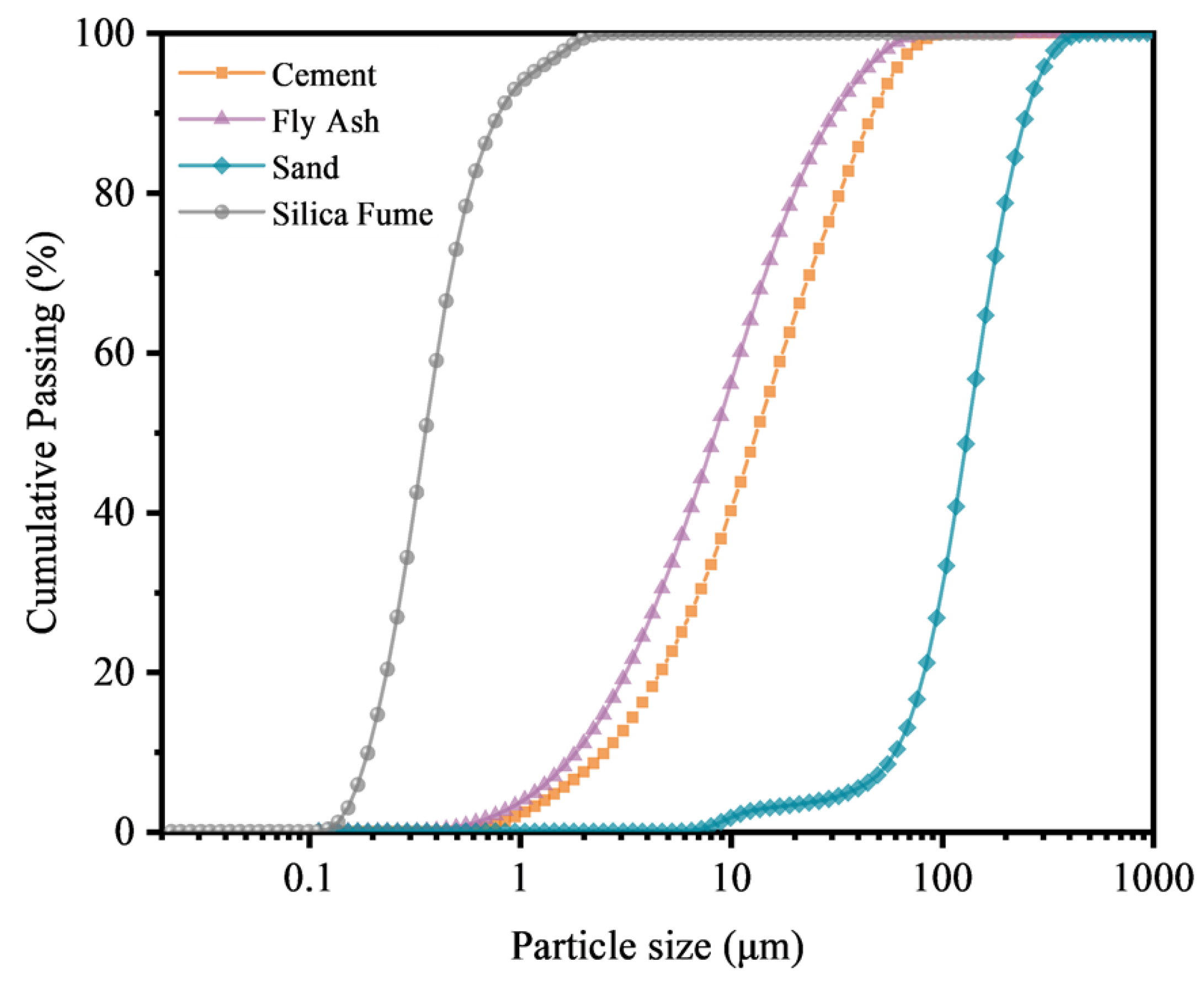
2.1. Raw Materials

The ordinary Portland cement (P.O.42.5) was from Yatai Group Harbin Cement Company, Harbin, China, fly ash (FA) was provided by a local power station, and silica fume (SF) was obtained from Elkem Asia (Mumbai, India). The chemical compositions of the cement, FA, and SF are presented in Table 1. The particle size distribution of the ingredients is shown in Figure 1. Shanghai Sunrise Polymer Material Co., Ltd., Shanghai, China, supplied polycarboxylate ether superplasticizer (SP, 40 wt. %). The particle size of silica sand was 60–150 μm. PE fibers were chosen, and their properties are detailed in Table 2. Sodium hydroxide (NaOH, analytical pure) was supplied by Xilong Scientific Group Co., Ltd., Chengdu, China. FAC was obtained from Henanborun Co., Ltd., Anyang, China. n-octadecane (ODE, industrial grade) was purchased from Shanghai Biyang Industrial Co., Ltd., Shanghai, China.

2.2. Preparation of ODE/FAC Composite PCM

The preparation process of ODE/FAC form-stable PCM was as follows (Figure 2). FAC was immersed in the NaOH solution and stood for 2 h. Then, FAC particles were transferred into a beaker containing deionized water for 4 h. Thereafter, it can be found that most of the FAC particles sank to the bottom of the beaker, which indicated the successful perforation of FAC. Subsequently, the perforated FAC particles were dried at 105 °C for 48 h in a drying oven. Then, the melted ODE was immersed into the cavity of the perforated FAC via the vacuum impregnation method at −0.08 mpa for 2 h. Lastly, ODE/FAC was obtained after suction filtration.

2.3. Mixed Proportion of Heat-Stored ECC

The mixed proportions of heat-stored ECC are presented in Table 3. ODE/FAC composite PCMs were incorporated into ECC by partially replacing the aggregate, and the replacement levels were 0 vol.%, 5 vol.%, 10 vol.%, and 20 vol.%, respectively. The specific preparation of heat-stored ECC was as follows. The cement, fly ash, silica fume, silica sand, and ODE/FAC were mixed in a mixer for 1 min. After the solid components were mixed well, the water and superplasticizer mixture was added slowly while mixing at a low speed (60 rpm) until the mixture showed a flow pattern, and then PE fibers were added slowly. The mixing was performed continuously at a slow speed (60 rpm) for 4 min from the start of water addition to fiber addition and then switched to a fast speed (120 rpm) for 6–7 min to prevent fiber agglomeration. The freshly mixed paste was molded, and the specimens were covered with cling film to prevent moisture loss. After 24 h of curing at room temperature of 20 ± 2 °C and with a relative humidity greater than 95%, the specimens were removed from the molds and placed in a steam oven at 60 °C for three days. At the end of the curing period, all specimens were removed and left in the laboratory for one day to prepare them for measurement.

2.4. Testing Methods

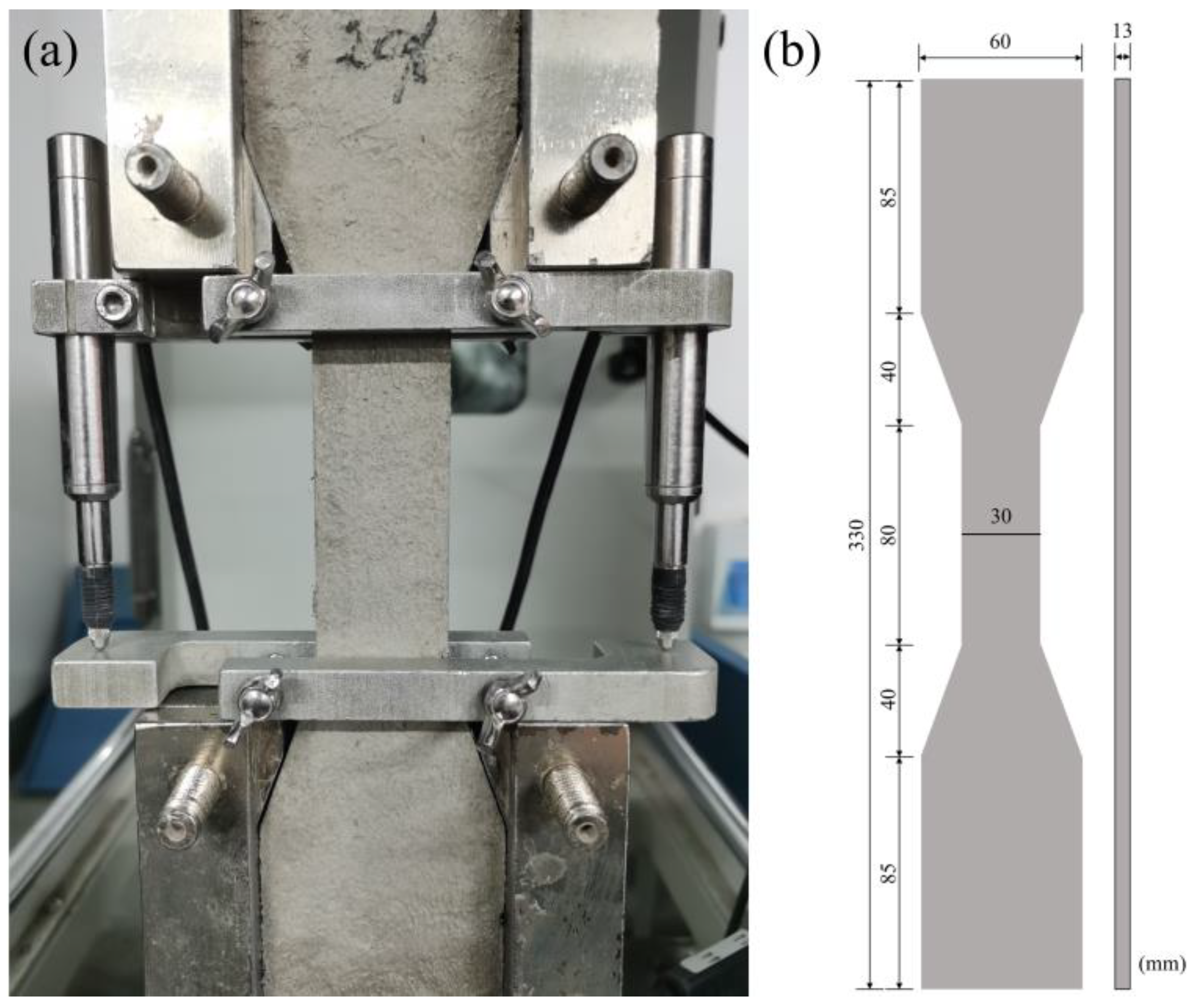
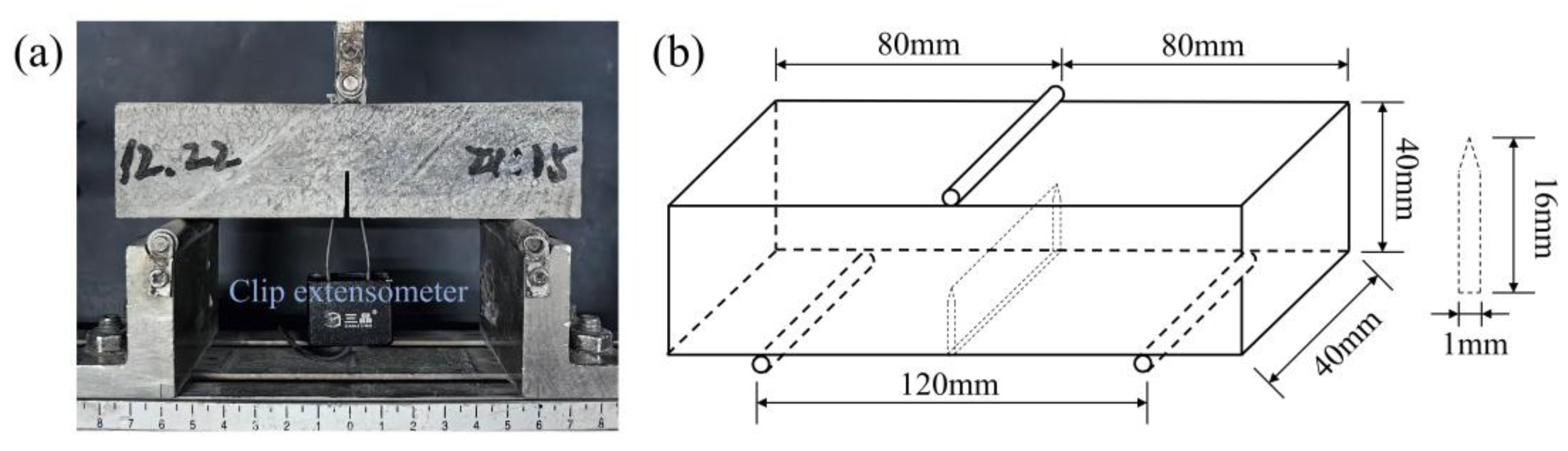
2.4.1. Mechanical Tests

For the flexural and compressive strength of heat-stored ECC specimens, three and six specimens were, respectively, used and tested using a microcomputer automatic cement compression and bending tester (YAW-300) at loading rates of 50 N/s and 2.4 kN/s, respectively, according to the Chinese National Standard GB/T 1346-2011 [19]. The dimensions of the flexural test specimens were 40 mm (W) × 40 mm (H) × 160 mm (L), and the dimensions of the compressive test specimens were cubes with a side length of 40 mm. The uniaxial tensile test of ECC specimens was carried out based on the dumbbell-type specimen recommended by JSCE [20]. The specimen dimensions and test setup are shown in Figure 3. The test was carried out on a universal material testing machine, and the loading mode was displacement loading with a loading rate of 0.5 mm/min. During the test, the system automatically recorded the tensile load, and the strain in the tensile zone of the specimen was collected by two linear variable differential transducers (LVDTs) fixed on the specimen. For each group, four specimens were tested.
The modulus of elasticity and fracture toughness of the matrix were assessed by three-point bending tests, as shown in Figure 4a. The specimen was a 40 mm (W) × 40 mm (H) × 160 mm (L) notched beam with a pre-notch cut at mid-span to a depth of 16 mm, as shown in Figure 4b. A hydraulic universal machine was used to load at a loading rate of 0.05 mm/s, and a clip extensometer recorded the crack mouth opening displacement (CMOD). The tests were performed according to the standard method for fracture testing (ASTM E399-ASTM E399-S) [21].
The modulus of elasticity Em and fracture toughness Km of the matrix can be calculated by the following Equations (1)–(3) [22]:
K m = 1.5 P max S a 0 t h 2 1.99 a 0 h ( 1 a 0 h ) 2.15 3.93 a 0 h + 2.7 a 0 h 2 ( 1 + 2 a 0 h ) ( 1 a 0 h ) 3 / 2  
E m = 1 t c i [ 3.70 + 32.60 t a n 2 ( π 2 a 0 + h 0 h + h 0 ) ]
c i = V i F i
where Pmax represents the peak load, S is the span of the notched specimen, t is the thickness of the specimen, h is the height of the specimen, h0 is the thickness of the thin steel plate at the knife edge of the clip extensometer, and a0 is the crack length. Ci represents the slope of the elastic phase of the test line. Calculated from any point in the straight-line segment of the ascending section of the test curve of the specimen, Vi and Fi are the crack width and load values at that point, respectively.

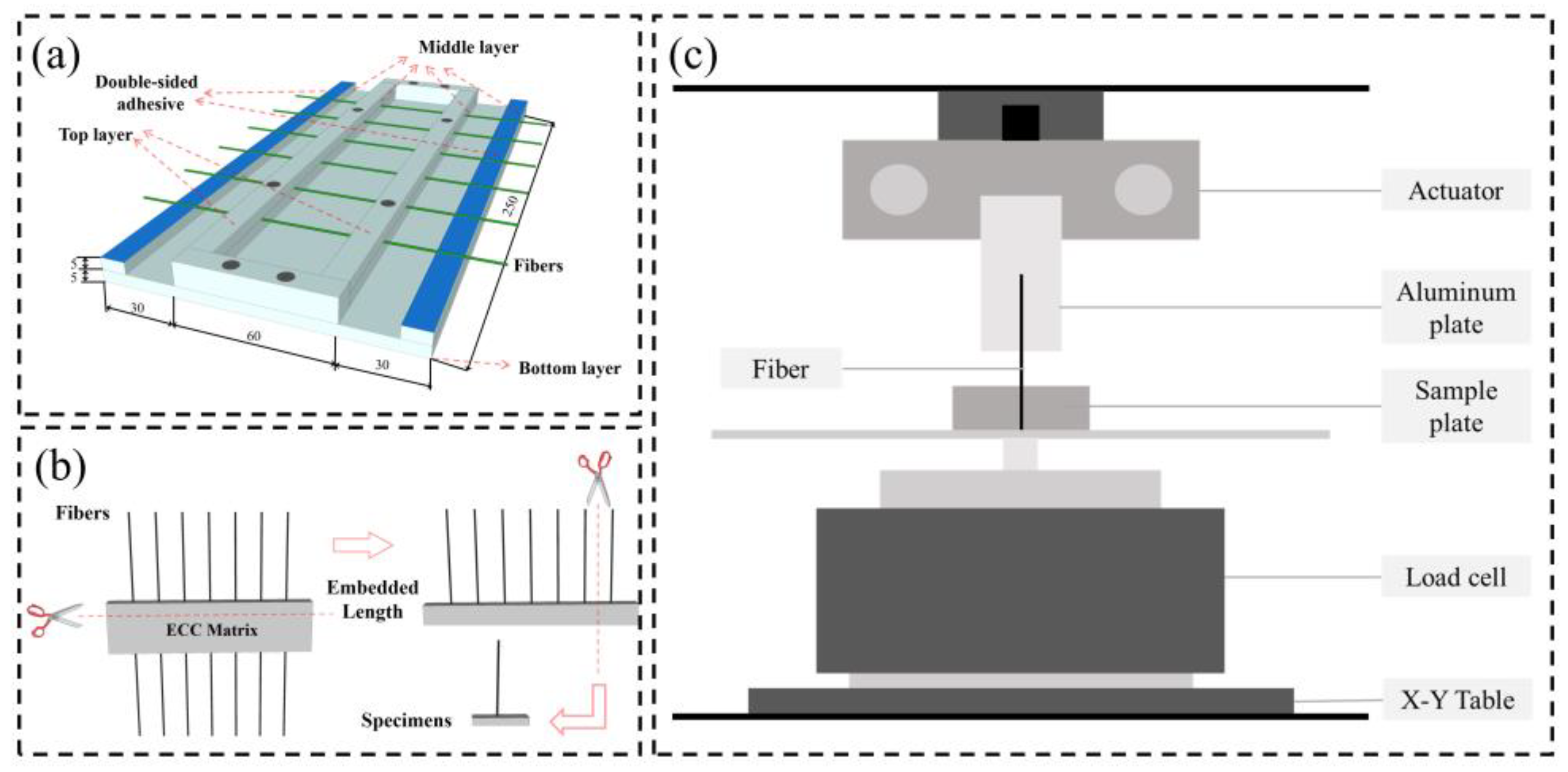
2.4.2. Single-Fiber Pullout Test

The frictional bond strength at the fiber–matrix interface was obtained by the single-fiber pullout test [23]. The mixing ratio of the specimens did not contain fibers, and the rest of the components were the same as the corresponding ECC. Figure 5a shows the mold used to prepare the single-fiber pullout specimens. During the preparation, long PE fibers were first glued onto the interlayer at equal intervals with double-sided adhesive. After fixing the fibers, a freshly mixed cement–mortar matrix without fibers was poured into the molds. The specimens were taken out of the molds after 24 h and transferred to a steam oven at 60 °C for 3 days. The cured specimens were cut using a precision cutter, as shown in Figure 5b. The embedding depth of the fibers was controlled to about 5 mm, and the embedding depth of the fibers in the specimen was equal to the thickness of the specimen. The cut specimens were tested using the device shown in Figure 5c. The test procedure started by gluing the specimen to the lower fixture fixed on the X-Y table. The free end of the fiber needed to be glued with high-strength glue to an aluminum plate fixed on the upper fixture, which was fixed on top of a transducer with a range of 10 N and an accuracy of 0.001 N. The test was conducted in the displacement-loading mode with a 0.5 mm/min loading speed. According to Equation (4), the interfacial frictional bond strength between the fibers and the matrix can be calculated [24].
τ 0 = P max / π d f L e
where τ0 is the fiber/matrix interface frictional bond strength, Pmax is the peak load, Le is the embedded length of the fiber, and df is the diameter of the fiber.

2.4.3. Characterization Methods

The thermal properties and microstructure of the forming-stable PCM samples were examined by differential scanning calorimetry (DSC, Netzsch, Selb, Germany, 200F3) and an environmental scanning electron microscope (SEM, FEI Co., Hillsboro, OR, USA, Quanta 200) analyses. The scanning rate of the DSC test from 5 °C to 55 °C is 5 K per minute. The thermal conductivity of heat-stored ECC was investigated by a laser thermal conductivity tester (Netzsch, Newsletter-LFA467) [25,26]. The thermal conductivity of heat-stored ECC specimens was evaluated by a hot-wire method via a measuring apparatus (Xi’an Xiatech, Xi’an, China, TC3000)

3. Results and Discussion

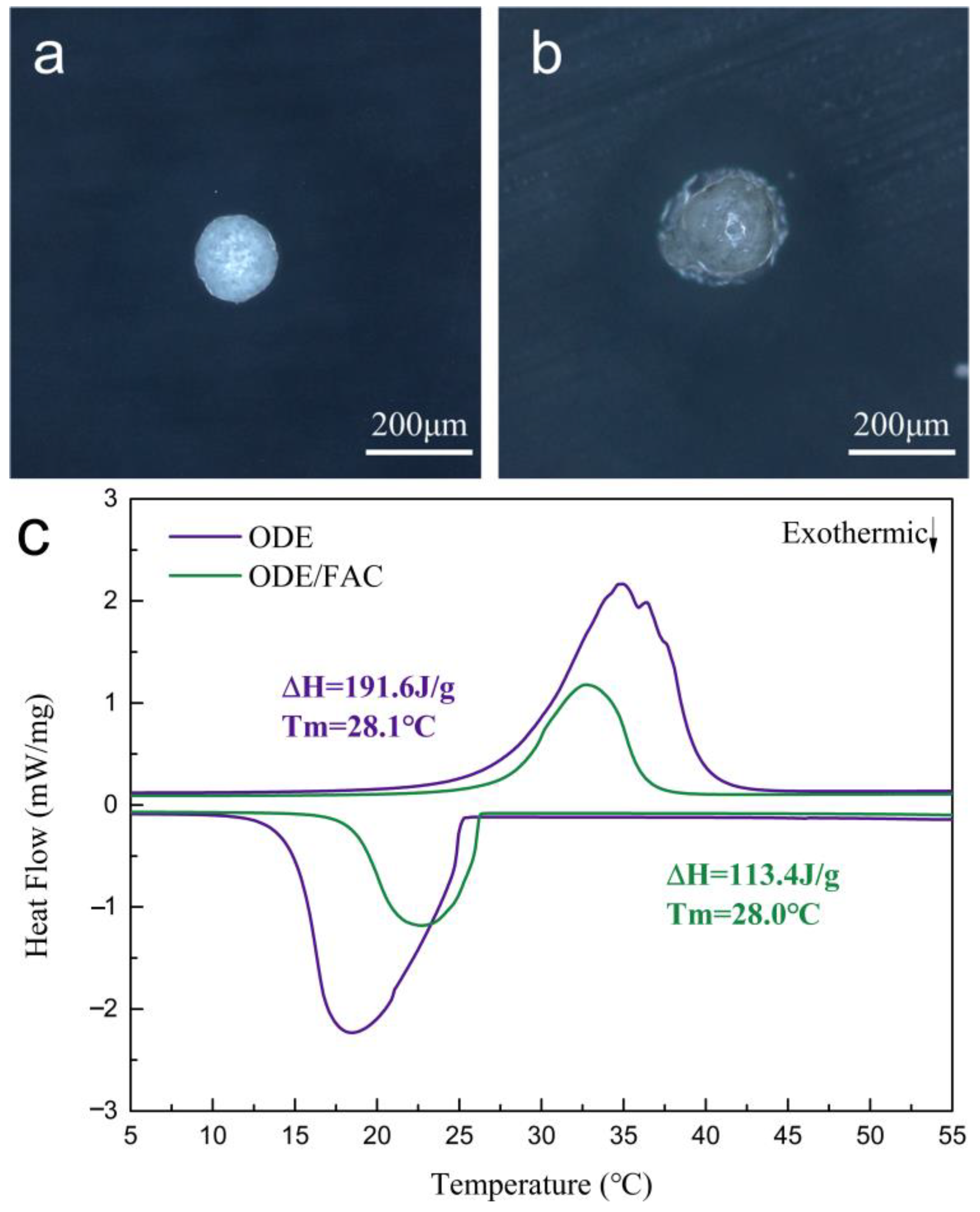
3.1. Micromorphology and Phase Transition Properties of ODE/FAC

Figure 6a,b presented the micromorphologies of the perforated FAC and ODE/FAC composite PCM. Clearly, the perforated FAC was a near-spherical shape and its appearance was white. After the impregnation of the melted ODE, partial ODE was injected into the cavity and the other part of ODE was wrapped around the surface of the FAC shell. Figure 5c shows the DSC curves of pure ODE and ODE/FAC composite PCM. There was a set of endothermic and exothermic peaks from the thermogram of ODE with a large latent heat of 191.6 J/g, and its melting temperature (i.e., phase transition temperature) was 28.1 °C, which was extremely suitable for building thermal management [27]. In contrast, the melting temperature of ODE/FAC (28.0 °C) was not much different from that of pure ODE. However, the melting enthalpy of ODE/FAC was decreased to 113.4 J/g, which can be attributed to the no latent heat storage capacity of FAC.

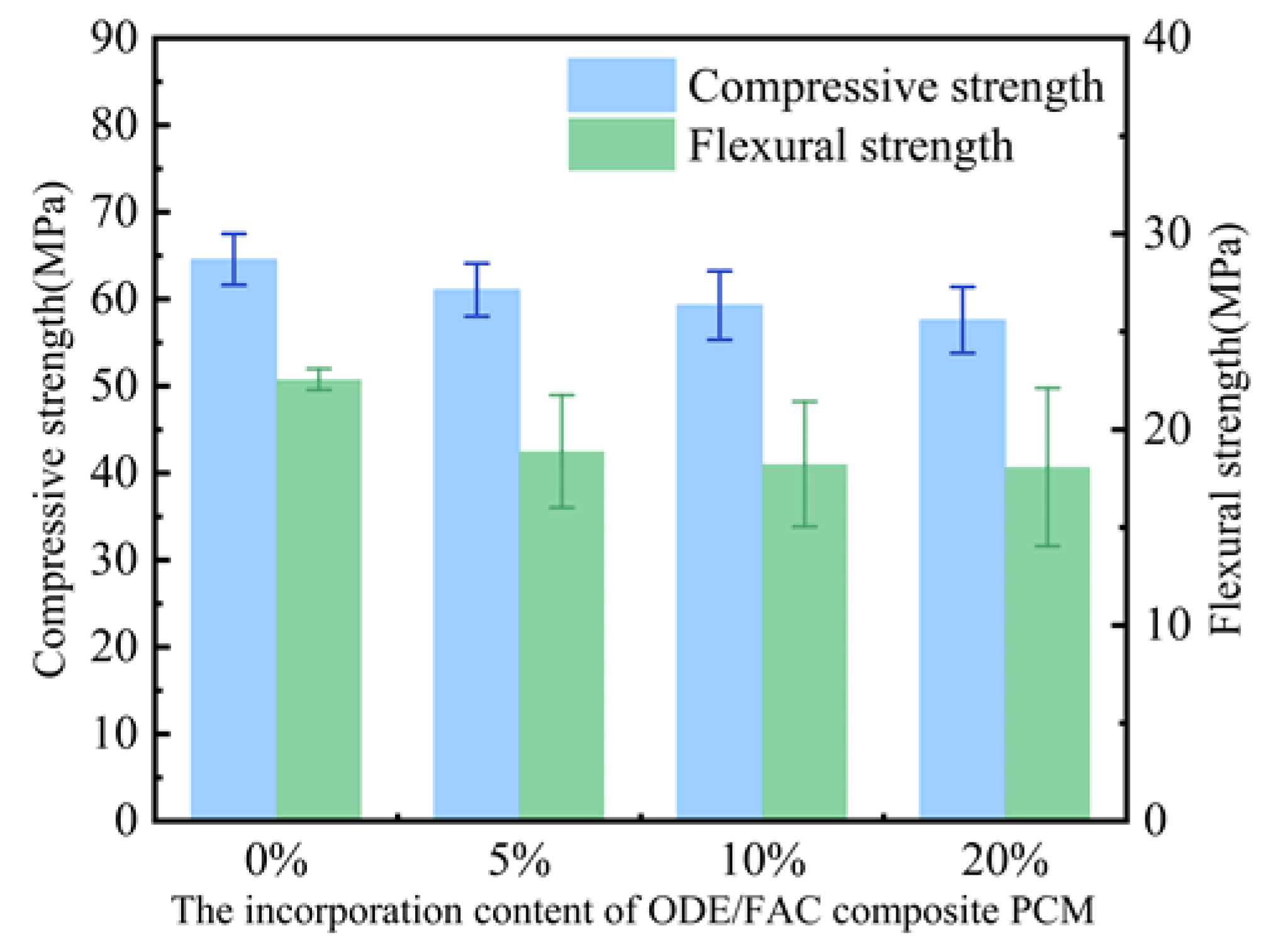
3.2. Flexural Strength and Compressive Strength of Heat-Stored ECC

Flexural and compressive strength tests were conducted at room temperature to evaluate the influence of ODE/FAC composite PCM on the mechanical properties of heat-stored ECCs. As shown in Figure 7, the compressive strength of heat-stored ECC decreased continuously with the increasing addition of ODE/FAC composite PCM. Compared to the control group (i.e., pure ECC), the compressive strengths of heat-stored ECC with 5 vol.%, 10 vol.%, and 20 vol.% ODE/FAC composite PCM decreased from 64.56 MPa to 61.06 MPa, 59.28 MPa and 57.59 MPa, respectively. The flexural strengths of heat-stored ECC also decreased with the increase in the amount of ODE/FAC composite PCM. The flexural strengths of heat-stored ECC specimens with different ODE/FAC composite PCM dosages were 18.88 MPa, 18.23 MPa, and 18.08 MPa, respectively, compared to the 22.56 MPa of the control group. This contradicted the traditional view that there was a loss of mechanical properties when microencapsulation was added to cement-based materials. The two main reasons for the loss of mechanical properties of conventional cement materials were the following: (1) microencapsulated PCMs usually exhibit low strength; (2) microencapsulated PCMs act as pores or defects in the cement matrix, and the overall porosity of cement composites increases with the increase in PCM content. However, the incorporation of fibers might play an important role in preventing the drastic decrease in mechanical properties and obtaining high-performance structural composites. The added fibers bound the matrix material around the particles at the microscopic scale and provided resistance under tensile strain by load transfer in adjacent fibers, increasing the fiber bridging along cracks, which resulted in a triaxial compression state. This results in significant compensation for the loss of compressive strength of traditional cement-based materials with the addition of microencapsulated PCM, highlighting the unique advantages of ECC.

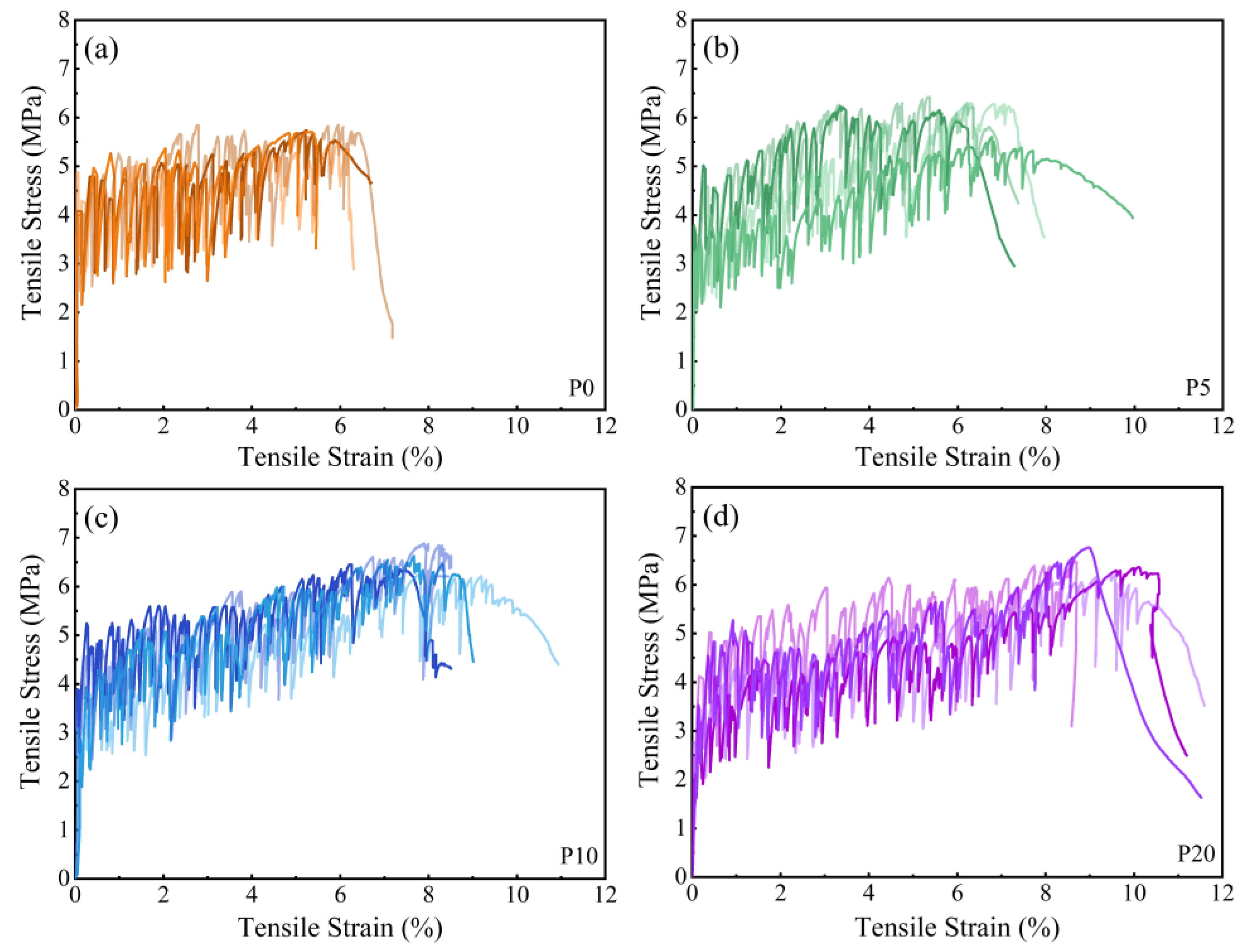
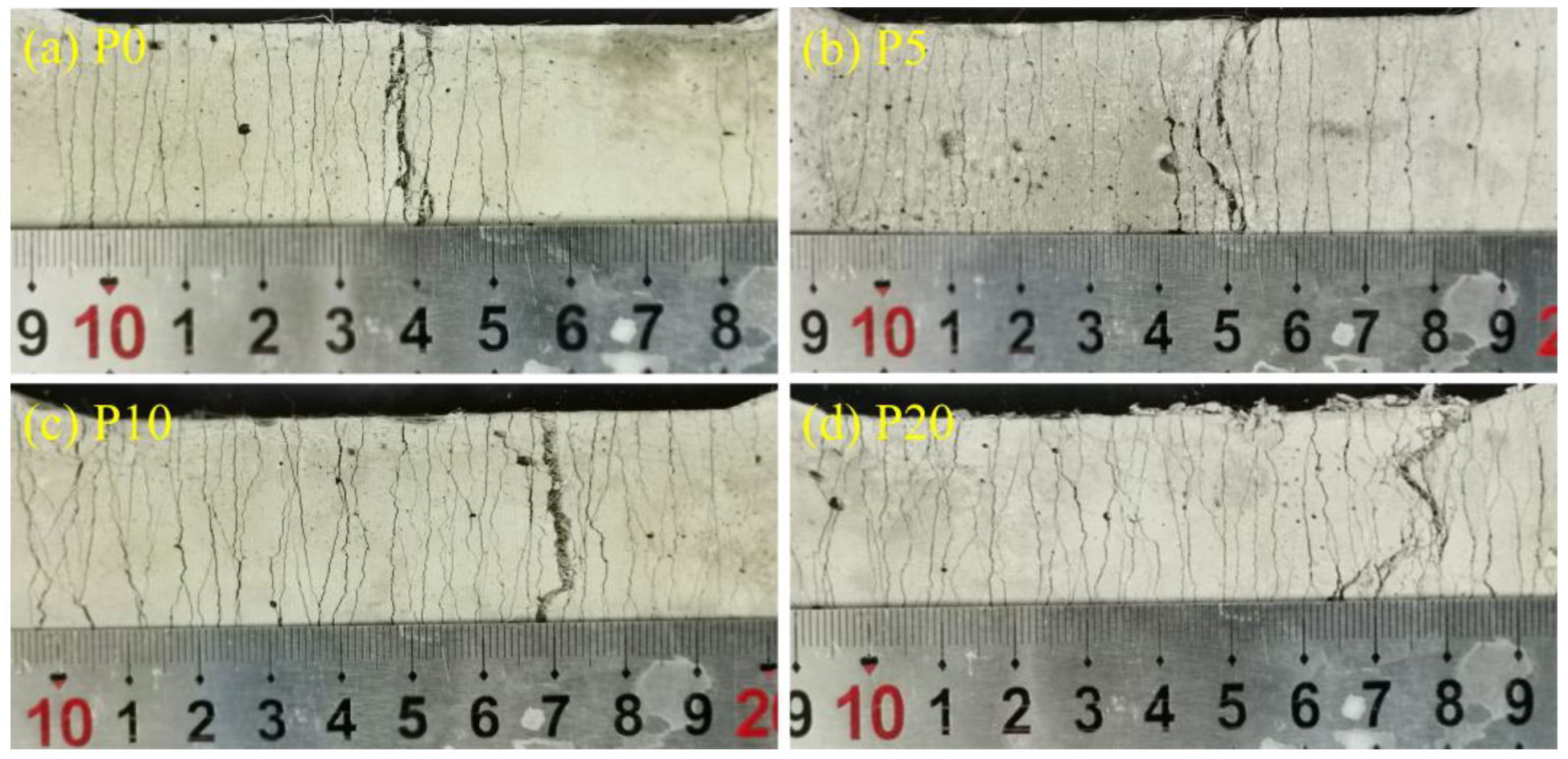
3.3. Uniaxial Tensile Properties

The uniaxial tensile stress–strain curves of heat-stored ECC specimens with different contents of ODE/FAC composite are shown in Figure 8. The curves consisted of three main stages, as shown in Figure 9. The first stage was the elasticity stage, in which the stress of the tensile specimen increased sharply with the increase in strain, and the stress–strain curve was linear until the specimen produced the first crack when it ended and entered the next stage. The second stage was the strain-hardening stage. The first crack appeared on the surface of the specimen. The stress–strain curve showed a decreasing trend for the first time and then rose again, at which time the stress value was the initial cracking strength. After the bridging fiber was subjected to an external load, the number of cracks in the specimen increased with the increase in external load, the crack spacing decreased gradually, and the stress–strain curve showed a high-frequency fluctuation curve. The stress continued to increase with strain until the external load exceeded the maximum capacity of the bridging fibers. At this point, the maximum stress corresponded to the ultimate tensile strength, and the corresponding strain was the ultimate tensile strain. The third stage was the strain-softening phase, during which no new cracks formed. As the tensile strain increased, the weakest crack surfaces with the least fiber-bridging capacity continued to open, causing tensile stress to decrease continuously until failure. All specimens in the test exhibited the full three-stage behavior, demonstrating tensile strain hardening and a damage mode characterized by multiple cracking. The slope of the strain hardening stage of the specimens without ODE/FAC composite PCM was small, indicating a low degree of strain hardening. With the amount of ODE/FAC composite PCM dosage, the slope of the strain-hardening stage of the curve increased significantly, and the addition of ODE/FAC composite PCM promoted the strain-hardening behavior of the ECC specimens.
From the results of uniaxial tensile tests in Table 4, it can be seen that the cracking strength of ECC specimens decreased with the increase in ODE/FAC composite PCM content. The cracking strength of specimen P0 was 4.24 MPa, while specimens P5 and P20 were 3.28 MPa and 2.69 MPa, with decreases of 22.64% and 36.56%, respectively. The tensile strength of the specimens increased with the increase in the dosage of ODE/FAC composite PCM. The tensile strength of specimen P0 was 5.70 MPa, whereas the tensile strength of specimens P5 and P20 were 6.08 MPa and 6.46 MPa, with an increase of 6.67% and 13.33%, respectively. The tensile strain of the heat-stored ECC specimens increased significantly with the increase in ODE/FAC composite PCM content. The tensile strain of pure ECC was 5.62%, while the maximum value of heat-stored ECC was 9.34%, when the ODE/FAC composite content was 20 vol.%. The tensile strain of the specimen was affected by the number of cracks and crack width of ECC. Clearly, the number of cracks in ECC increased significantly with the increase in ODE/FAC composite content, which was the main reason for the increase in the strain of the specimen. As shown in Figure 10, the number of cracks increased significantly with the increase in PCM content, the crack spacing decreased significantly, and the crack width also became considerably smaller.

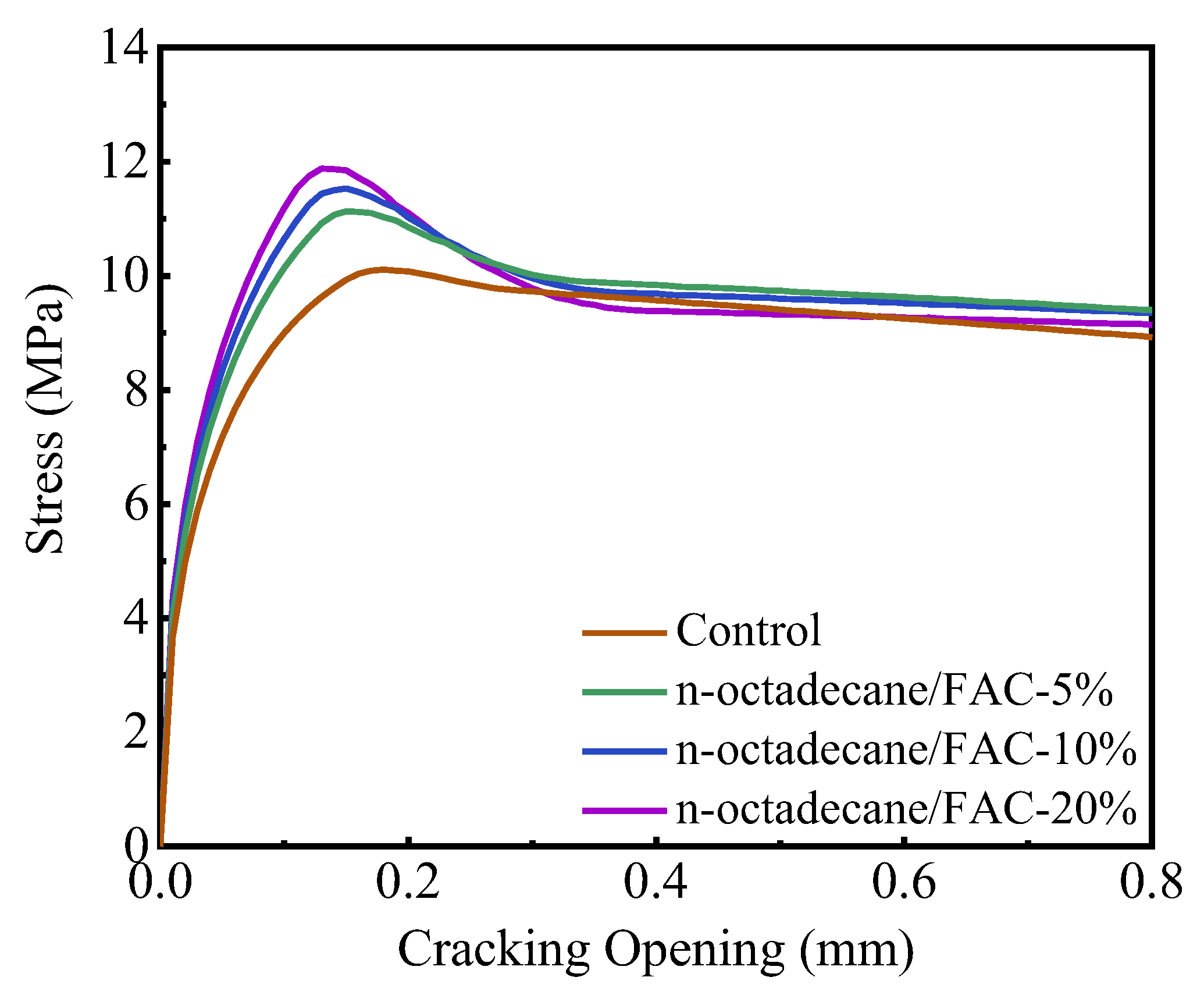
3.4. Micromechanical Analysis

Three-point bending tests on prismatic specimens with notches were carried out to measure the modulus of elasticity and fracture toughness of heat-stored ECC. The calculated results of the fracture toughness and modulus of elasticity are demonstrated in Figure 11. The fracture toughness and Young’s matrix modulus of heat-stored ECC were decreased with the increase in ODE/FAC composite content. The fracture toughness and Young’s modulus of heat-stored ECC decreased by 18.68% and 20.73%, when ODE/FAC composite content was increased from 0 to 20 vol.%. This was similar to the results for compressive strength.
The effect of ODE/FAC composite PCM content on the interfacial properties of PE fibers and cement matrix was analyzed by monofilament pullout tests, the results are shown in Figure 12. Figure 12 shows that the load of fibers at similar burial depths increased with the increase in ODE/FAC composite PCM content, which indicated that the friction at the interface was increasing.
The interfacial friction in the monofilament pullout tests with different ODE/FAC composite content was calculated and shown in Table 5. It can be seen that ODE/FAC composite significantly improved the interfacial friction between fiber and cement matrix; the friction coefficient between the matrix and the fiber without ODE/FAC composite addition was 1.098 MPa, while the interfacial friction coefficient between the matrix and the fiber with 5 vol.% ODE/FAC composite content was 1.199 MPa, which was improved by 9.20%. The interfacial friction was 1.385 MPa when the ODE/FAC composite content was 20 vol.%, which was improved by 26.02% compared to the specimen without ODE/FAC composite. This was due to the fact that the micro-filler effect of ODE/FAC, which filled the pores and cracks in the transition zone, resulted in a reduction in the gaps and cracks in the transition zone between the fiber and the matrix. Therefore, increasing the densification of the interfacial transition zone can increase the interfacial friction. The micro-filler effect is a phenomenon in gelled composites in which fine particles (e.g., fly ash, silica fume, or other fillers) help to fill the voids and pores in the ITZ, resulting in a tighter and stronger bond between the matrix and the fibers [28,29,30,31]. Secondly, like rubber, a material with similar surface properties, PCM can connect cracks and act as a bridging element for cracks, preventing the expansion of micro-cracks [32].
The micromechanical parameters used as inputs in modeling the σ-δ relationship are given in Table 6, including matrix, fiber, and interface parameters. According to the experimental results, the interfacial friction, matrix cracking strength, and modulus of elasticity were changed with the ODE/FAC composite content. However, according to the previous literature all other parameters were shown to be unaffected and hence the parameters were considered as constants. Based on the obtained frictional bond strength τ0 at the fiber/matrix interface and the other parameters that were listed in Table 6, the process of fiber pullout at both ends was simulated by numerical analysis, and the bridging stress–crack opening displacement curves of the fibers were obtained [33,34]. Considering the fiber pullout at both ends, the crack opening distance δ is jointly contributed by the pullout distance of the fiber at the longer end of the embedment depth (δl) and the pullout distance of the fiber at the shorter end of the embedment depth (δs). For a given δ, the values of δl and δs are calculated for each step based on the fiber’s internal force balance. Then, by increasing the value of σ through repeated iterations, the monofilament pullout curve considering fiber pullout at both ends can be calculated. According to the probability density function of fiber angle and burial depth, the number of fibers with different angles of burial depth can be calculated when the fiber volume fraction is fixed. Finally, the final fiber bridging curve can be obtained by accumulating the internal forces of all fibers together as shown in Figure 13. The fiber crack bridging behavior depended on the interaction between the fiber, matrix, and interface properties. Considering the same fibers prepared, the shape of the σ-δ curve was mainly influenced by the matrix and interface properties. From the curves in Figure 13, it can be seen that with the increase in ODE/FAC composite content, there was a tendency for the crack opening displacement to decrease under the compound effect of increased interfacial bonding and weakened matrix while the bridging stress increases.
Based on the ECC micromechanical design model, the ability of ECC to achieve the multi-seam cracking and strain-hardening behavior required the satisfaction of a strength criterion and an energy criterion based on Equations (5)–(7) [37]. These were the strength criterion that required the initial crack strength σfc to be less than the maximum bridge stress σ0, which the bridging fibers can provide, and the energy criterion that requires the required complementary energy to be greater than the fracture toughness of the crack tip, respectively. Based on the basis of the design criterion, two pseudo-strain-hardening (PSH) indices were defined to describe the potential for the strain hardening of the specimen quantitatively, PSHstrength and PSHenergy, as shown in Equations (8) and (9) [38]. Thus, these two criteria quantitatively evaluated the strain-hardening potential of heat-stored ECC at different ODE/FAC composite content.
σ 0 > σ f c
J b σ 0 δ 0 0 δ 0 σ δ d δ > J t i p
J t i p = K m 2 E m
P S H s t r e n g t h = σ 0 / σ f c
P S H e n e r g y = J b / J t i p
where δ0 is the crack opening at the maximum bridging stress σ0.
Based on the above model, the calculated maximum bridge stress, initial crack strength, crack tip fracture toughness, compensatory energy, and PSH index of the obtained heat-stored ECC specimens are shown in Table 7. The strain-hardening index was greater than 1, which was the critical condition for the ability of materials to produce strain-hardening. The essential values of PSHstrength and PSHenergy for pureECC to be able to saturate cracking were 1.2 and 3, respectively. The values were much larger than the value of heat-stored ECC, so all the specimens were able to show a saturated multi-seam cracking mode. The results showed that the increase in ODE/FAC composite content can significantly increase the value of the PSH index. When the content of the ODE/FAC composite gradually increased from 0 vol.% to 20 vol.%, the PSHstrength gradually increased from 2.38 to 4.42, and the value of the PSHenergy gradually increased from 22.46 to 31.71. Therefore, the possibility of saturation cracking of heat-stored ECC increased with increasing ODE/FAC composite contents, corresponding to an increase in tensile strain capacity.

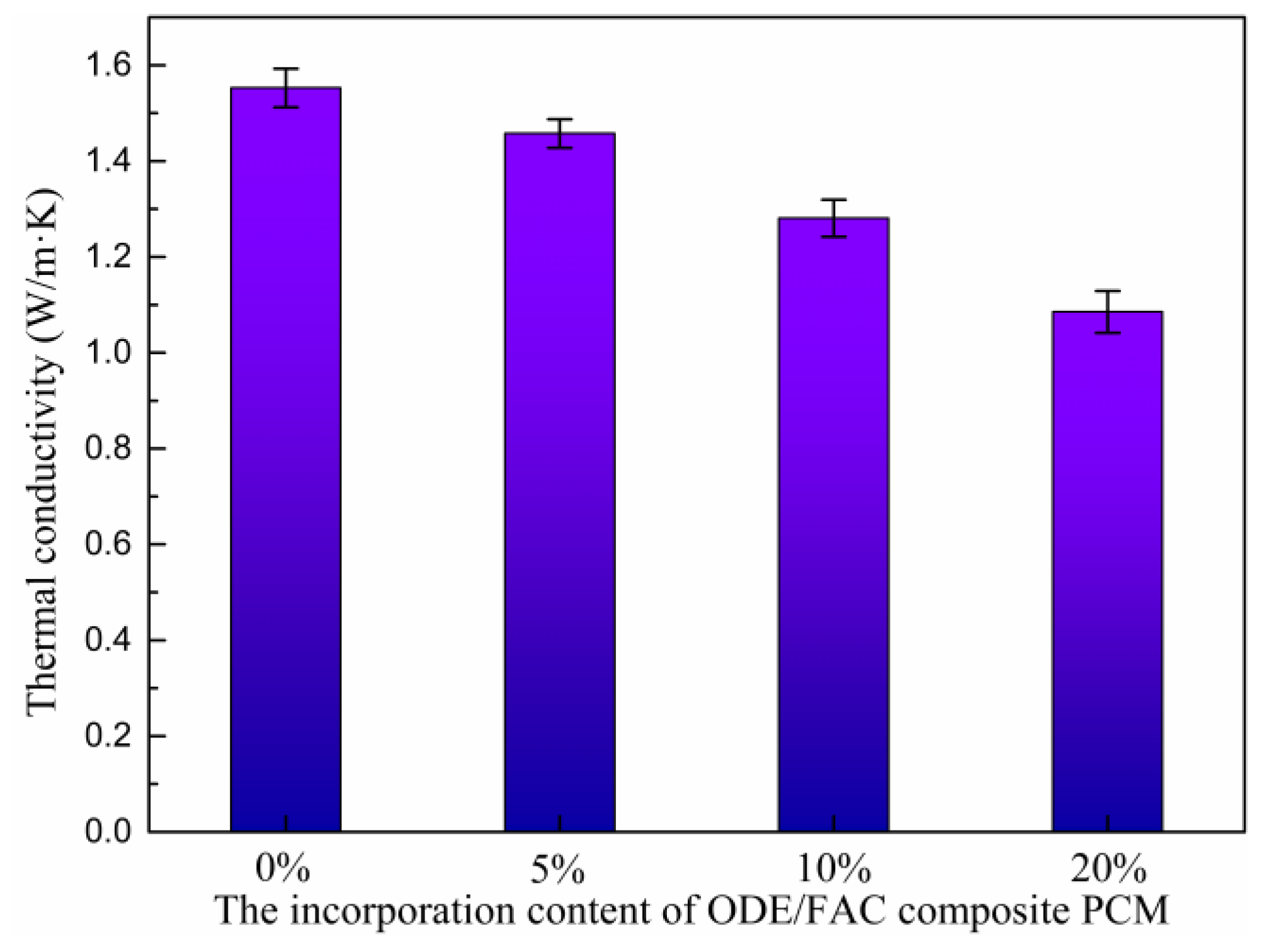
3.5. Thermal Conductivity of Heat-Stored ECC

Figure 14 presents the thermal conductivities of heat-stored ECC with different ODE/FAC composite PCM contents. It can be seen that the thermal conductivity of heat-stored ECC exhibited a gradually decreased trend as the incorporation content of ODE/FAC composite PCM increased. To be specific, the thermal conductivities of heat-stored ECCs with 0 vol.%, 5 vol.%, 10 vol.%, and 20 vol.% were 1.5525 W/m·k, 1.4574 W/m·k, 1.2806 W/m·k, and 1.08533 W/m·k, respectively. The results were widespread in the previous literature about heat-stored building materials with PCM [10,39]. Obviously, the decreased heat-transfer performance indicated the enhanced thermal energy storage capacity of heat-stored ECC.

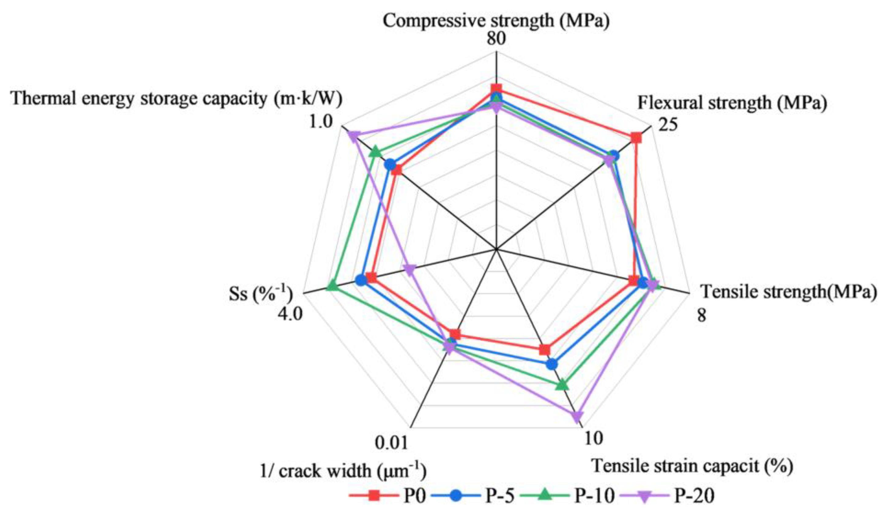
3.6. Evaluating the Effect of ODE/FAC Composite PCM on the Performance of Heat-Stored ECC

For ECC, strength indicators, such as compressive, flexural, and tensile strength, and ductility indicators, such as tensile strain capacity, are important mechanical properties indicators. These indicators provide insight into the ability of the material to withstand loads and resist cracking or failure. Therefore, in order to have a comprehensive understanding of the effect of ODE/FAC composite PCM contents on the mechanical and thermal storage properties of ECC, a seven-dimensional radar chart was used for a comprehensive evaluation. As shown in Figure 15, the seven dimensions are compressive strength, flexural strength, tensile strength, tensile strain resistance, inverse of crack width, inverse of standard deviation of tensile strain (Ss), and thermal storage capacity. Among them, the inverse of crack width and the inverse of the standard deviation of tensile strain are crucial for the durability performance of ECC [40]. Specifically, they reflect the material’s ability to limit crack propagation and prevent the ingress of hazardous materials, thereby improving the long-term durability of the structure. Meanwhile, smaller Ss are more favorable to the self-repairing performance and stability of ECC against multiple cracking. The thermal storage capacity is then reflected by the reciprocal of the thermal conductivity, with a decrease in heat transfer properties indicating an increase in the thermal storage capacity of the thermal storage ECC. The normalized area results of the seven-dimensional radargrams for evaluating the overall performance of ECCs are shown in Table 8. Overall, the overall performance of the material was maximized as the ODE/FAC composite PCM contents increased from 0% to 10%. However, the radar plot area decreased with a further increase in the ODE/FAC composite PCM contents. Therefore, the optimum value of the ODE/FAC composite PCM contents is selected as 10% considering all the properties of the material.

4. Conclusions

In this study, a novel microencapsulated PCM with an ODE core and a FAC shell was developed and it was used as an ultrafine aggregate to replace silica sand to produce heat-stored ECC. Based on the testing of mechanical properties including flexural strength, compressive strength, and tensile properties, the increase in ODE/FAC composite PCM content reduced the compressive strength, flexural strength, and tensile cracking strength of heat-stored ECC, and the tensile strength and tensile strain showed an increasing trend. The addition of ODE/FAC composite PCM also increased the number of cracks and reduced the crack width of heat-stored ECC in the uniaxial tensile test. The overall performance of heat-stored ECC was still better than that of the low-content group, although the dispersion was higher when the ODE/FAC composite PCM dosage reached 20% due to uneven distribution. Adding ODE/FAC composite PCM increased the interfacial friction between the fibers and the cement matrix, and the specimen with 20 vol.% ODE/FAC composite PCM content increased the interfacial friction by 26.02% as compared to the specimen without ODE/FAC composite PCM. The micromechanical model analysis showed that the strength PSH index and energy PSH index of the heat-stored ECC specimens increased with increasing the amount of ODE/FAC composite PCM. This indicated that adding ODE/FAC composite PCM can improve the steady-state cracking and tensile strain-hardening ability of specimens with multiple cracks. In addition, the prepared heat-stored ECC also exhibited a good thermal energy storage capacity due to the decreased heat transfer performance.
Further research will explore the long-term durability and self-healing behavior of heat-stored ECC under varying thermal and mechanical loading conditions will be critical to ensuring its suitability for real-world applications. The integration of heat-stored ECC into diverse structural elements, such as building facades, pavements, and other critical infrastructure, has the potential to significantly enhance the energy efficiency and sustainability of construction systems. By improving the material’s ability to regulate temperature and reduce energy consumption, this approach could contribute to more environmentally friendly and cost-effective building solutions. In addition, future studies will also focus on the scalability of this approach and the cost-effectiveness of incorporating ODE/FAC into large-scale ECC production.

Author Contributions

Conceptualization, H.S., K.Y. and Y.L.; methodology, K.Y. and Y.L.; software, H.S.; validation, M.J., Z.W. and Y.Y.; formal analysis, M.J.; investigation, Z.W.; resources, M.J. and Z.W.; data curation, H.S.; writing—original draft preparation, H.S.; writing—review and editing, K.Y. and Y.L.; visualization, K.Y.; supervision, Y.L. and Y.Y.; project administration, Y.L.; funding acquisition, Y.L. All authors have read and agreed to the published version of the manuscript.

Funding

This research was funded by State Key Laboratory of Silicate Materials for Architectures (Wuhan University of Technology, grant number SYSJJ2023-02) and National Natural Science Foundation of China (grant number 51902068).

Institutional Review Board Statement

Not applicable.

Informed Consent Statement

Not applicable.

Data Availability Statement

The data presented in this study are available on request from the corresponding author.

Conflicts of Interest

The authors declare that there are no conflicts of interest regarding the publication of this paper.

References

  1. Ma, M.; Ma, X.; Cai, W.; Cai, W. Carbon-dioxide mitigation in the residential building sector: A household scale-based assessment. Energy Convers. Manag. 2019, 198, 111915. [Google Scholar] [CrossRef]
  2. Yu, K.; Jia, M.; Tian, W.; Yang, Y.; Liu, Y. Enhanced thermo-mechanical properties of cementitious composites via red mud-based microencapsulated phase change material: Towards energy conservation in building. Energy 2024, 290, 130301. [Google Scholar] [CrossRef]
  3. Xu, B.; Li, Z. Performance of novel thermal energy storage engineered cementitious composites incorporating a paraffin/diatomite composite phase change material. Appl. Energy 2014, 121, 114–122. [Google Scholar] [CrossRef]
  4. Yu, K.; Jia, M.; Liu, Y.; Yang, Y. Binary decanoic acid/polyethylene glycol as a novel phase change material for thermal energy storage: Eutectic behaviors and energy conservation evaluation. J. Energy Storage 2023, 68, 107663. [Google Scholar] [CrossRef]
  5. Mohtasim, M.S.; Das, B.K. MXene based composite phase change materials for thermal energy storage applications: Featuring bio-mimic approaches. Renew. Sustain. Energy Rev. 2025, 207, 114952. [Google Scholar] [CrossRef]
  6. Yu, K.; Liu, C.; Li, L.; Tian, W.; Yang, Y.; Liu, Y. Carbon-negative heat-stored limestone calcined clay cement mortar containing form-stable phase change materials. J. Clean. Prod. 2024, 437, 140703. [Google Scholar] [CrossRef]
  7. Yu, K.; Liu, Y.; Jia, M.; Wang, C.; Yang, Y. Thermal energy storage cement mortar containing encapsulated hydrated salt/fly ash cenosphere phase change material: Thermo-mechanical properties and energy saving analysis. J. Energy Storage 2022, 51, 104388. [Google Scholar] [CrossRef]
  8. Wong, W.P.; Kagalkar, A.; Patel, R.; Patel, P.; Dharaskar, S.; Walvekar, R.; Khalid, M.; Gedam, V.V. Nano-enhanced phase change materials for thermal energy storage: A comprehensive review of recent advancements, applications, and future challenges. J. Energy Storage 2023, 74, 109265. [Google Scholar] [CrossRef]
  9. Junaid, M.F.; Rehman, Z.U.; Ijaz, N.; Farooq, R.; Khalid, U.; Ijaz, Z. Performance evaluation of cement-based composites containing phase change materials from energy management and construction standpoints. Constr. Build. Mater. 2024, 416, 135108. [Google Scholar] [CrossRef]
  10. Li, M.; Shi, J. Review on micropore grade inorganic porous medium based form stable composite phase change materials: Preparation, performance improvement and effects on the properties of cement mortar. Constr. Build. Mater. 2019, 194, 287–310. [Google Scholar] [CrossRef]
  11. Lee, J.; Wi, S.; Yun, B.Y.; Yang, S.; Park, J.H.; Kim, S. Development and evaluation of gypsum/shape-stabilization phase change materials using large-capacity vacuum impregnator for thermal energy storage. Appl. Energy 2019, 241, 278–290. [Google Scholar] [CrossRef]
  12. Drissi, S.; Mo, K.H.; Falchetto, A.C.; Ling, T.-C. Understanding the compressive strength degradation mechanism of cement-paste incorporating phase change material. Cem. Concr. Compos. 2021, 124, 104249. [Google Scholar] [CrossRef]
  13. Jia, M.; Yu, K.; Liu, Y.; Yang, Y. Enabling superior thermo-mechanical performance of hydrated salt-based phase change energy storage cementitious composite using graphene oxide reinforced micro-interface. J. Build. Eng. 2023, 76, 107166. [Google Scholar] [CrossRef]
  14. Zhang, D.; Yu, J.; Wu, H.; Jaworska, B.; Ellis, B.R.; Li, V.C. Discontinuous micro-fibers as intrinsic reinforcement for ductile Engineered Cementitious Composites (ECC). Compos. Part B Eng. 2020, 184, 107741. [Google Scholar] [CrossRef]
  15. Yu, J.; Yao, J.; Lin, X.; Li, H.; Lam, J.Y.K.; Leung, C.K.Y.; Sham, I.M.L.; Shih, K. Tensile performance of sustainable Strain-Hardening Cementitious Composites with hybrid PVA and recycled PET fibers. Cem. Concr. Res. 2018, 107, 110–123. [Google Scholar] [CrossRef]
  16. Yu, J.; Chen, Y.; Leung, C.K.Y. Mechanical performance of Strain-Hardening Cementitious Composites (SHCC) with hybrid polyvinyl alcohol and steel fibers. Compos. Struct. 2019, 226, 111198. [Google Scholar] [CrossRef]
  17. Huang, B.-T.; Li, Q.-H.; Xu, S.-L.; Zhou, B.-M. Tensile fatigue behavior of fiber-reinforced cementitious material with high ductility: Experimental study and novel P-S-N model. Constr. Build. Mater. 2018, 178, 349–359. [Google Scholar] [CrossRef]
  18. Mechtcherine, V.; Millon, O.; Butler, M.; Thoma, K. Mechanical behaviour of strain hardening cement-based composites under impact loading. Cem. Concr. Compos. 2011, 33, 1–11. [Google Scholar] [CrossRef]
  19. Zhang, H.; Liang, Q.; Shao, M.; Jiang, N.; Ma, W.; Ge, Z.; Šavija, B. Optimization of low-carbon lightweight foamed concrete using ground circulating fluidized bed fly ash. J. Clean. Prod. 2025, 489, 144697. [Google Scholar] [CrossRef]
  20. Yokota, H.; Rokugo, K.; Sakata, N. JSCE recommendations for design and construction of high performance fiber reinforced cement composite with multiple fine cracks. In High Performance Fiber Reinforced Cement Composites; Springer: Tokyo, Japan, 2008. [Google Scholar]
  21. ASTM E399-19; Standard Test Method for Plane-Strain Fracture Toughness KIc of Metallic Materials. ASTM International: West Conshohocken, PA, USA, 2019.
  22. Huang, B.-T.; Wu, J.-Q.; Yu, J.; Dai, J.-G.; Leung, C.K. High-Strength Seawater Sea-Sand Engineered Cementitious Composites (SS-ECC): Mechanical Performance and Probabilistic Modeling. Cem. Concr. Compos. 2020, 114, 103740. [Google Scholar] [CrossRef]
  23. Huang, Z.; Liang, T.; Huang, B.; Zhou, Y.; Ye, J. Ultra-lightweight high ductility cement composite incorporated with low PE fiber and rubber powder. Constr. Build. Mater. 2021, 312, 125430. [Google Scholar] [CrossRef]
  24. Curosu, I.; Muja, E.; Ismailov, M.; Ahmed, A.H.; Liebscher, M.; Mechtcherine, V. An Experimental-Analytical Scale-Linking Study on the Crack-Bridging Mechanisms in Different Types of SHCC in Dependence on Fiber Orientation. Cem. Concr. Res. 2022, 152, 106650. [Google Scholar] [CrossRef]
  25. Cheng, F.; Zhang, X.; Wen, R.; Huang, Z.; Fang, M.; Liu, Y.; Wu, X.; Min, X. Thermal Conductivity Enhancement of Form-Stable Tetradecanol/Expanded Perlite Composite Phase Change Materials by Adding Cu Powder and Carbon Fiber for Thermal Energy Storage. Appl. Therm. Eng. 2019, 156, 653–659. [Google Scholar] [CrossRef]
  26. Yousefi, A.; Tang, W.; Khavarian, M.; Fang, C. Development of Novel Form-Stable Phase Change Material (PCM) Composite Using Recycled Expanded Glass for Thermal Energy Storage in Cementitious Composite. Renew. Energy 2021, 175, 14–28. [Google Scholar] [CrossRef]
  27. Zhu, N.; Li, S.; Hu, P.; Wei, S.; Deng, R.; Lei, F. A Review on Applications of Shape-Stabilized Phase Change Materials Embedded in Building Enclosure in Recent Ten Years. Sustain. Cities Soc. 2018, 43, 251–264. [Google Scholar] [CrossRef]
  28. Lin, C.; Kanstad, T.; Jacobsen, S.; Ji, G. Bonding Property between Fiber and Cementitious Matrix: A Critical Review. Constr. Build. Mater. 2023, 378, 131169. [Google Scholar] [CrossRef]
  29. Gürbüz, E.; Erdem, S. Development and Thermo-Mechanical Analysis of High-Performance Hybrid Fibre Engineered Cementitious Composites with Microencapsulated Phase Change Materials. Constr. Build. Mater. 2020, 263, 120139. [Google Scholar] [CrossRef]
  30. Erdem, S.; Gürbüz, E. Influence of Microencapsulated Phase Change Materials on the Flexural Behavior and Micromechanical Impact Damage of Hybrid Fibre Reinforced Engineered Cementitious Composites. Compos. Part B Eng. 2019, 166, 633–644. [Google Scholar] [CrossRef]
  31. Zhang, Z.; Shen, Q.; Qin, F.; Abdalla, J.A.; Hawileh, R.A.; Xiong, Y. Expanded Vermiculite Acting as Artificial Flaws to Enhance the Tensile Properties of High-Strength Engineered Cementitious Composites. Constr. Build. Mater. 2024, 447, 138081. [Google Scholar] [CrossRef]
  32. Hou, M.; Xu, K.; Monteiro, P.J.M.; Li, V.C. Rubber Particle Bridging Effect on Crack Width Control of Low Carbon Engineered Cementitious Composites (ECC). Cem. Concr. Compos. 2023, 140, 105106. [Google Scholar] [CrossRef]
  33. Li, J.; Qiu, J.; Weng, J.; Yang, E.-H. Micromechanics of Engineered Cementitious Composites (ECC): A Critical Review and New Insights. Constr. Build. Mater. 2023, 362, 129765. [Google Scholar] [CrossRef]
  34. Lu, C.; Leung, C.K.Y. A New Model for the Cracking Process and Tensile Ductility of Strain Hardening Cementitious Composites (SHCC). Cem. Concr. Res. 2016, 79, 353–365. [Google Scholar] [CrossRef]
  35. Yang, E.-H.; Wang, S.; Yang, Y.; Li, V.C. Fiber-bridging constitutive law of engineered cementitious composites. J. Adv. Concr. Technol. 2008, 6, 181–193. [Google Scholar] [CrossRef]
  36. Ranade, R.; Li, V.C.; Stults, M.D.; Rushing, T.S.; Roth, J.; Heard, W.F. Micromechanics of high-strength, high-ductility concrete. ACI Mater. J. 2013, 110, 375. [Google Scholar]
  37. Li, V.C.; Leung, C. Steady-State and Multiple Cracking of Short Random Fiber Composites. J. Eng. Mech. 1992, 118, 2246–2264. [Google Scholar] [CrossRef]
  38. Kanda, T.; Li, V.C. Multiple Cracking Sequence and Saturation in Fiber Reinforced Cementitious Composites. Concr. Res. Technol. 1998, 9, 19–33. [Google Scholar] [CrossRef]
  39. Drissi, S.; Ling, T.-C.; Mo, K.H.; Eddhahak, A. A review of microencapsulated and composite phase change materials: Alteration of strength and thermal properties of cement-based materials. Renew. Sustain. Energy Rev. 2019, 110, 467–484. [Google Scholar] [CrossRef]
  40. Huang, B.-T.; Wu, J.-Q.; Yu, J.; Dai, J.-G.; Leung, C.K.Y.; Li, V.C. Seawater Sea-Sand Engineered/Strain-Hardening Cementitious Composites (ECC/SHCC): Assessment and Modeling of Crack Characteristics. Cem. Concr. Res. 2021, 140, 106292. [Google Scholar] [CrossRef]
Figure 1. Particle size distribution of the ingredients.
Coatings 15 00135 g001
Figure 2. Schematic illustration of preparing ODE/FAC composite PCM.
Coatings 15 00135 g002
Figure 3. Uniaxial tensile test: (a) the device and (b) the specimen dimensions.
Coatings 15 00135 g003
Figure 4. Fracture toughness test: (a) the device and (b) the specimen size.
Coatings 15 00135 g004
Figure 5. Single-fiber pullout test: (a) the mold, (b) the specimens, and (c) the device.
Coatings 15 00135 g005
Figure 6. Micromorphologies of (a) the perforated FAC and (b) ODE/FAC composite PCM, as well as (c) DSC curves of pure ODE and ODE/FAC composite PCM.
Coatings 15 00135 g006
Figure 7. Influence of ODE/FAC content on the flexural strength and compressive strength of heat-stored ECC.
Coatings 15 00135 g007
Figure 8. Tensile stress–strain curves of heat-stored ECC with different contents of ODE/FAC: (a) 0, (b) 5 vol.%, (c) 10 vol.%, and (d) 20 vol.%.
Coatings 15 00135 g008
Figure 9. ECC specimen crack propagation process under uniaxial tensile loading.
Coatings 15 00135 g009
Figure 10. Cracking morphology of heat-stored ECC specimens with different contents of ODE/FAC: (a) 0%, (b) 5 vol.%, (c) 10 vol.%, and (d) 20 vol.%.
Coatings 15 00135 g010
Figure 11. Fracture toughness and Young’s modulus of heat-stored ECC with different content of ODE/FAC composite.
Coatings 15 00135 g011
Figure 12. Single-fiber pullout curve of heat-stored ECC with different contents of ODE/FAC: (a) 0, (b) 5 vol.%, (c) 10 vol.%, and (d) 20 vol.%.
Coatings 15 00135 g012
Figure 13. Simulated σ-δ curves for ECC with different contents of ODE/FAC composite.
Coatings 15 00135 g013
Figure 14. Thermal conductivities of heat-stored ECC with different contents of ODE/FAC composite.
Coatings 15 00135 g014
Figure 15. Seven-dimensional analysis radar plot of ECC with different ODE/FAC composite PCM content.
Coatings 15 00135 g015
Table 1. Chemical compositions of cement, silica fume, and FA (wt. %).
IngredientsSiO2Al2O3CaOFe2O3K2OMgONa2OSO3
SAC21.45.4564.483.50.231.460.222.64
FA49.2227.83.141.291.060.860.920.16
SF95.10.50.60.454.120.71.310.50
Table 2. Physical and mechanical properties of PE fiber.
Type of
Fiber
Diameter (μm)Length (mm)Tensile Strength (MPa)Elastic Modulus (GPa)Density (g/cm3)
PE201838001130.97
Table 3. Mixed proportions of ECC in this study (kg/m3).
Mix IDCementFly AshSilica FumeWaterAggregateSPODE/FACPE Fiber
(1.5 vol.%)
P0533.2733.1566.65359.91479.885014.7
P5533.2733.1566.65359.91455.8958.8114.7
P10533.2733.1566.65359.91431.59517.6314.7
P20533.2733.1566.65359.91383.90535.2514.7
Table 4. Uniaxial tensile of heat-stored ECC.
Mixture IDFirst Cracking Strength
(MPa)
Tensile Strength
(MPa)
Ultimate Strain (%)Crack NumbersAverage Crack Spacing
(mm)
Residual Crack Width
(μm)
P04.24 ± 0.635.70 ± 0.215.62 ± 0.4821.50 ± 4.503.72209.12
P53.28 ± 0.506.08 ± 0.486.44 ± 0.8627.25 ± 4.252.94189.06
P103.23 ± 0.476.53 ± 0.357.64 ± 0.4933.25 ± 3.252.48183.82
P202.69 ± 0.846.46 ± 0.329.34 ± 1.0341.00 ± 5.001.95182.24
Table 5. The fiber/matrix interface’s frictional bond strength in heat-stored ECC.
SpecimenP0P5P10P20
τ 0 (MPa)1.098 ± 0.2121.199 ± 0.1151.289 ± 0.1621.385 ± 0.291
Table 6. Micromechanical parameters.
Micromechanical ParametersP0P5P10P20
FiberFiber length, Lf (mm)18 a18 a18 a18 a
Fiber diameter, df (μm)20 a20 a20 a20 a
Fiber elastic modulus, Ef (GPa)113 a113 a113 a113 a
Fiber strength, σfu (MPa)3800 a3800 a3800 a3800 a
Fiber strength reduction factor, f’0.33 b0.33 b0.33 b0.33 b
InterfaceInterfacial chemical bond, Gd (J/m2)0 b0 b0 b0 b
Interfacial frictional bond, τ0 (MPa)1.098 c1.199 c1.289 c1.385 c
Slip-hardening coefficient, β0 b0 b0 b0 b
Subbing coefficient, f0.59 b0.59 b0.59 b0.59 b
MatrixElastic modulus, Em (MPa)33.39 c29.77 c27.99 c26.47 c
Cracking strength, σfc (MPa)4.24 c3.28 c3.23 c2.69 c
Note: a Nominal properties from Table 2; b these values were assumed according to Refs [35,36]; c test results in this study.
Table 7. Uniaxial tensile of ECC.
Mixture IDσfc (MPa)σ0 (MPa)PSHstrengthJb’ (J/m2)Jtip (J/m2)PSHenergy
P04.2410.112.38385.1017.1522.46
P53.2811.133.39432.8914.8629.13
P103.2311.533.57446.4714.5430.71
P202.6911.884.42453.7014.3131.71
Table 8. Normalized areas of seven-dimensional assessment.
SpecimenP0P5P10P20
Normalized areas1.2171.3471.5701.467
Disclaimer/Publisher’s Note: The statements, opinions and data contained in all publications are solely those of the individual author(s) and contributor(s) and not of MDPI and/or the editor(s). MDPI and/or the editor(s) disclaim responsibility for any injury to people or property resulting from any ideas, methods, instructions or products referred to in the content.

