Article

Performance Reinforcement of Basalt Fiber–Reinforced Polymer by Guiding  Hierarchical Aramid/Zirconia Hybrid Fiber

1
Shock and Vibration of Engineering Materials and Structures Key Lab of Sichuan Province, School of Materials and Chemistry, Southwest University of Science and Technology, No. 59 Middle Section of Qinglong Avenue, Fu Cheng District, Mianyang 621010, China
2
Department of Plasticity, Lomonosov Moscow State University, Moscow 119991, Russia
3
Department of Technological Machinery and Equipment, Fergana State Technical University, Fergana 150100, Uzbekistan
4
School of Aerospace Engineering, Tsinghua University, Beijing 100084, China
5
School of Mechanical Engineering, University of Western Australia, Perth 6009, Australia
*
Authors to whom correspondence should be addressed.
Coatings 2025, 15(11), 1356; https://doi.org/10.3390/coatings15111356
Submission received: 16 October 2025 / Revised: 11 November 2025 / Accepted: 18 November 2025 / Published: 20 November 2025

Abstract

Hierarchical aramid/zirconia hybrid fibers were introduced into the interlayers of basalt fiber–reinforced polymer (BFRP) composites to optimize their interlaminar properties. The reinforcing effect of micro/nano aramid short fiber (MNASF) and zirconia fiber (ZF) on BFRP composites at different mass ratios was investigated through three-point bending (3PB) tests and compression tests. The results demonstrated that the BFRP composites incorporating 2 wt.% MNASF and 2 wt.% ZF exhibited the most significant property enhancement. The 3PB tests revealed increases in flexural strength and modulus of 119.2% and 62.6%, respectively, compared to the unreinforced BFRP composites. Compression tests showed that this specific formulation enhanced the compressive strength and modulus by 257.7% and 121.6%, respectively. Scanning electron microscopy and optical microscopy observations indicated that the incorporation of MNASF and ZF effectively reduced the volume fraction of resin-rich regions in the interlaminar regions, and the dominant failure mode transitioned from delamination to shear failure. Overall, the introduction of MNASF and ZF effectively combined the reinforcing effects of the two fibers, improving the mechanical properties of BFRP composites.

1. Introduction

Carbon fiber–reinforced polymer (CFRP) is a lightweight, high-strength, corrosion-resistant, fatigue-resistant, and highly tailorable composite material [1,2,3], with widespread applications in aerospace, rail transit, and construction engineering. However, the sophisticated production process and costly raw materials of carbon fiber (CF) lead to high manufacturing costs. Therefore, in civilian applications with low structural strength requirements, the use of CFRP composites provides properties that exceed the actual requirements, making it a less preferred material choice.
Basalt fiber–reinforced polymer (BFRP) is an environmentally friendly, high-property composite consisting of a polymer matrix and basalt fiber (BF) [4,5,6]. It exhibits excellent properties, including lightweight, high strength, high-temperature resistance, corrosion resistance, and good designability [7,8,9,10,11]. BF is produced from widely available and inexpensive raw materials, resulting in a production cost significantly lower than that of CF. This inherent cost advantage makes BFRP a more cost-effective material than CFRP. These characteristics position BFRP as an excellent, cost-effective substitute for CFRP in civilian applications with moderate property demands, suggesting considerable potential for widespread adoption.
The fiber surfaces in laminated composites are often chemically inert, resulting in insufficient adhesion at the interface between the fiber layers and the polymer matrix [12,13]. These poorly bonded interfaces consequently act as structural defects and stress concentration points. Furthermore, the brittle resin-rich region is typically prevalent in the interlaminar areas of the composite. Under an applied load, microcracks therefore tend to initiate from these critical sites of weakness.
To address the delamination of laminated composites under external load, various methods have been proposed, such as stitching [14], tufting [15], 3D weaving [16], and Z-pinning [17]. However, these techniques often involve complex manufacturing processes and high costs. Furthermore, these processes may cause mechanical damage that impairs the mechanical properties of the composites. Therefore, introducing fibers into the interlayers of laminated composites to mitigate interlayer defects is a widely used toughening strategy. Sohn et al. [18] proposed introducing randomly distributed short fibers into the interlayer to improve the delamination resistance of laminated composites. In their work, they introduced 5 mm to 7 mm long aramid fibers into the interlayer of CF/epoxy resin composites. Experiments showed that the model II interlaminar fracture toughness (GIIC) increased approximately twofold. Zheng et al. [19] introduced three different types of short fibers, namely CF, flax fiber, and aramid fiber, into the interlayer of CF/epoxy resin composites. They investigated the effect of different chopped fibers on the model I interlaminar fracture toughness (GIC) of composites. The results showed that short-cut aramid fibers had the best toughening effect, with GIC increasing by 94.8%.
However, introducing a single type of fiber to reinforce composites raises the following issues: (1) This results in a low proportion of Z-directional fibers between layers, making it difficult to construct effective Z-directional fiber-bridging structures and leading to poor through-thickness reinforcement. (2) The morphology and dimensions of a single fiber are monotonous, resulting in an interlayer reinforcement structure that lacks multi-scale protection capability and has limited resistance to microcrack propagation. To overcome these limitations, researchers have introduced two or more toughening materials into the interlayers of laminated composites in a hybrid fiber toughening strategy to explore their synergistic mechanisms [20,21,22,23]. Saghaf et al. [24] simultaneously applied polyvinylidene fluoride (PVDF) and polysulfone (PSF) in the form of nanofibers to CFRP. The results of the study indicate that when two single-component fibers were introduced separately, GIIC increased by 57% and 7%, respectively. When the PVDF/PSF hybrid fiber was introduced, GIIC increased by 75%. When PSF and PVDF are used as hybrid toughening agents, the microcracks that are generated need to overcome the effects of both fibers simultaneously, causing the crack path to deviate, achieving a synergistic toughening effect. Li et al. [25] also used electrospinning to introduce multi-walled carbon nanotubes-epoxy (MWNTS-EP) and PSF in the form of nanofibers into CF/epoxy composites. Experiments show that the introduced hybrid nanofibers exhibit a clear preferential orientation. Phase separation of mixed nanofibers promotes the formation of network structures. These network structures are conducive to load transfer, crack bridging, crack deflection, and crack pinning.
The experiments conducted by the above researchers demonstrated the advantages of introducing mixed fibers for interlayer toughening: (1) the introduction of multiple fibers can optimize Z-directional distribution through size complementarity and morphological integration, enabling the construction of multi-scale Z-directional fiber-bridging structures that significantly enhance the through-thickness reinforcement; (2) the various fibers introduced can be combined at the micron and even nanometer scale to form multi-scale fiber-network structures due to their differentiated sizes. This fiber network can resist microcrack propagation at the multi-scale, enhancing the ability of composites to inhibit microcrack initiation and propagation. The introduction of multiple fibers can combine the reinforcing effects of different fibers while improving several key mechanical properties of composites. Introducing two or more fibers to reinforcing laminated composites is an effective composite reinforcement [26,27,28,29,30,31].
Micro/nano aramid short fiber (MNASF) is a nanoscale polymer fiber composed of para-aromatic polyamide molecular chains. It shares the same molecular formula as conventional aramid fiber, thereby inheriting its excellent properties, including high strength, high modulus, and chemical corrosion resistance [32]. The length of MNASF is approximately 1–3 mm, and the diameter of the main trunk is about 20 µm, as shown in Figure 1. MNASF consists of a disordered distribution of main branches and tree-like side branches. The mechanical claw structure formed by it can effectively embed into the fiber layer to form a fiber bridging, thereby reinforcing the material properties of the composites [33,34]. Zirconia fiber (ZF) is a high-property fiber made from zirconium, which has many excellent properties such as acid resistance, alkali resistance, and corrosion resistance [35,36,37,38]. The length of ZF is approximately 1–2 mm, and the diameter of the main trunk is about 10 µm, as shown in Figure 1. When embedded into the fiber layers, ZF forms multidirectional flexible pins [39] that act as reinforcements by constructing fiber-bridging structures between interlaminar regions. The two fibers are incorporated into BFRP composites to create a multi-scale network structure, which effectively reduces the volume of the resin-rich region. Under molding pressure, the unique micro–nano structure of MNASF expands and embeds into the basalt fiber layers via mechanical interlocking. Simultaneously, ZF penetrates the resin-rich regions and interfaces to form pinned connections. The synergistic effect between these fibers effectively suppresses microcrack initiation and propagation, leading to a significant enhancement in the interlaminar properties of the BFRP composites.
This study investigates the influence of MNASF and ZF proportions on BFRP composites by evaluating flexural and compressive properties through three-point bending and compression tests. Optical microscopy (OM) and scanning electron microscopy (SEM) are employed to analyze the interlayer fiber distribution and fracture surface morphology, investigating the reinforcement mechanism of the hierarchical aramid/zirconia hybrid fibers.

2. Composite Design, Manufacture, and Characterization

2.1. Design Concept of Hierarchical Aramid/Zirconia Hybrid Fiber-Reinforced BFRP Composites

This study seeks to optimize the interlayer structure of BFRP composites and enhance their interfacial bonding properties. To achieve this, MNASF and ZF with varying mass ratios were incorporated into the BFRP composite interlayers. The distributed hierarchical aramid/zirconia hybrid fibers between the fiber layers effectively alleviated interlayer defects through three primary mechanisms. Firstly, mechanical interlocking between MNASF and ZF resulted in the formation of a multi-scale fiber network within the resin layer. This network enhanced the load transfer efficiency, reduced the volume of the resin-rich region, and mitigated the brittleness of the resin. Secondly, the embedment of fine MNASF branch fibers and ZF pins into the BF layer surfaces enabled the formation of Z-directional fiber bridging within the interfacial transition region. Thirdly, the penetration of MNASF through one or two BF layers promoted multi-level deflection of microcrack propagation paths, thereby altering the microcrack trajectory from horizontal to vertical. These mechanisms collectively enhanced the mechanical properties of the BFRP composites.
The content of MNASF and ZF must be controlled within an optimal range. An insufficient fiber content was ineffective in reducing the volume fraction of the resin-rich region or facilitating the formation of effective bridging structures, which consequently compromised the mechanical properties. Conversely, excessive fiber content led to a resin deficiency, resulting in incomplete fiber impregnation and the formation of defects.

2.2. Major Raw Materials and Preparation

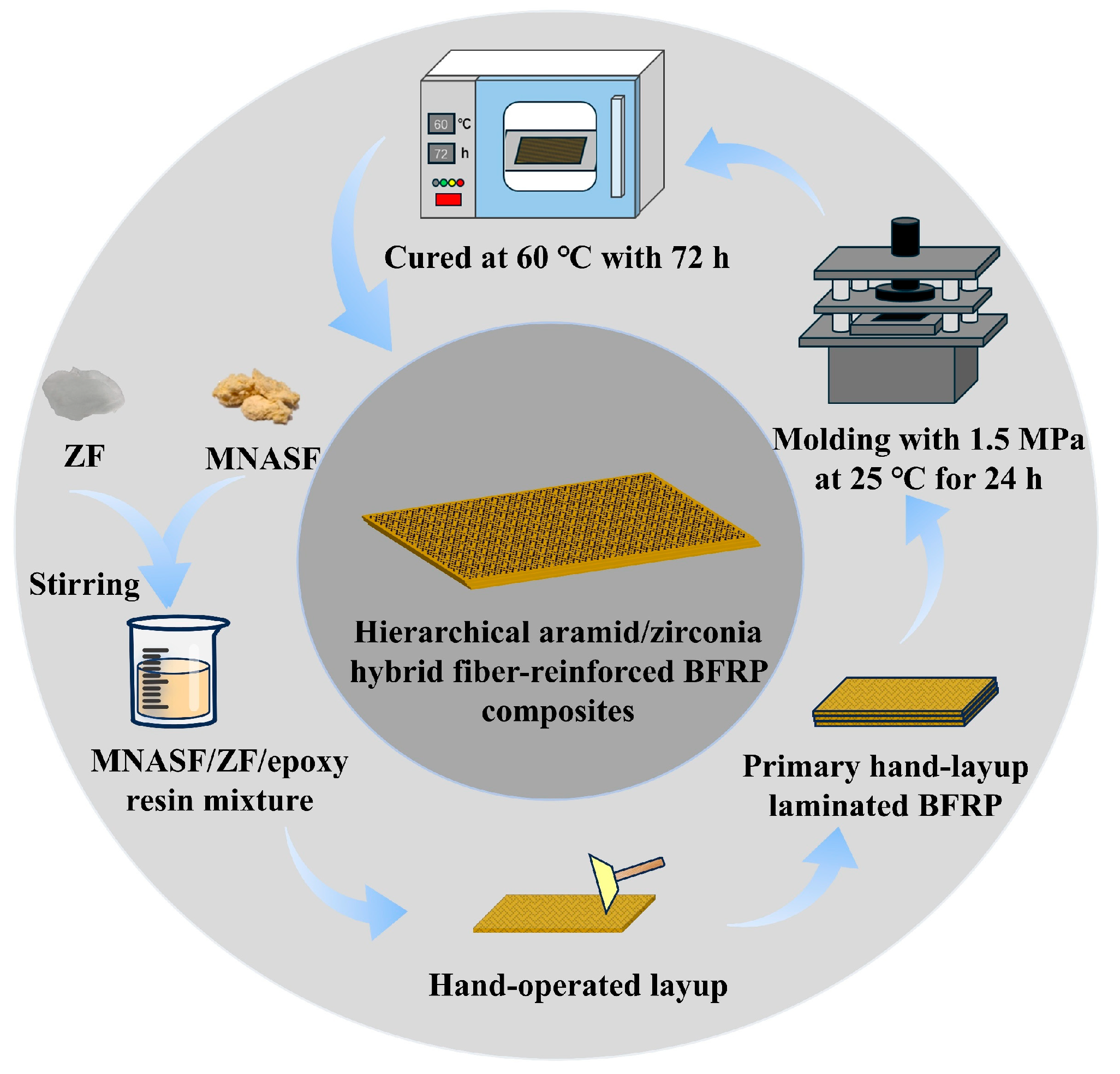
The main characteristics of the experimental starting materials, including their names, physical forms, main features, and suppliers, were summarized in Table 1. The BFRP composites reinforced by hierarchical aramid/zirconia hybrid fibers were prepared as shown in Figure 2.
MNASF and ZF were weighed until the total mass was equivalent to 4 wt.% (80 g) of the resin. The mass ratios of MNASF to ZF were designed as 0/4, 1/3, 2/2, 3/1, and 4/0. Subsequently, each sample was mixed with acetone and stirred continuously for 30 min. The resulting dispersion was blended thoroughly with 80 g of epoxy resin. Afterwards, the mixture was placed in a fume hood until the acetone evaporated completely, yielding a uniform MNASF/ZF/epoxy mixture.
According to the specified mass ratio of 5/1 for the resin and hardener, the hardener was added proportionally to the MNASF/ZF/epoxy mixture with different mass ratios. After mixing thoroughly, a uniform MNASF/ZF/epoxy/hardener mixture was achieved. The resulting mixture was then evenly applied onto the surface of pre-cut BF fabric using the hand lay-up technique. Subsequently, through repeated stacking of the basalt fiber fabrics and multiple coating applications using the hand lay-up technique, a layered BFRP composite preform containing 10 layers of BF was eventually fabricated.
The compression molding process parameters were set with a molding temperature of 20 °C, and the molding pressure was set to 1.5 MPa. After compression molding for 24 h, incompletely cured hierarchical aramid/zirconia hybrid fiber-reinforced BFRP composites were obtained. Following demolding, the specimen was placed in an oven at 60 °C for a 72 h post-curing process. The final products were the fully cured hierarchical aramid/zirconia hybrid fiber-reinforced BFRP composites. Their detailed information was provided in Table 2.

2.3. Tests and Characterizations of Composites

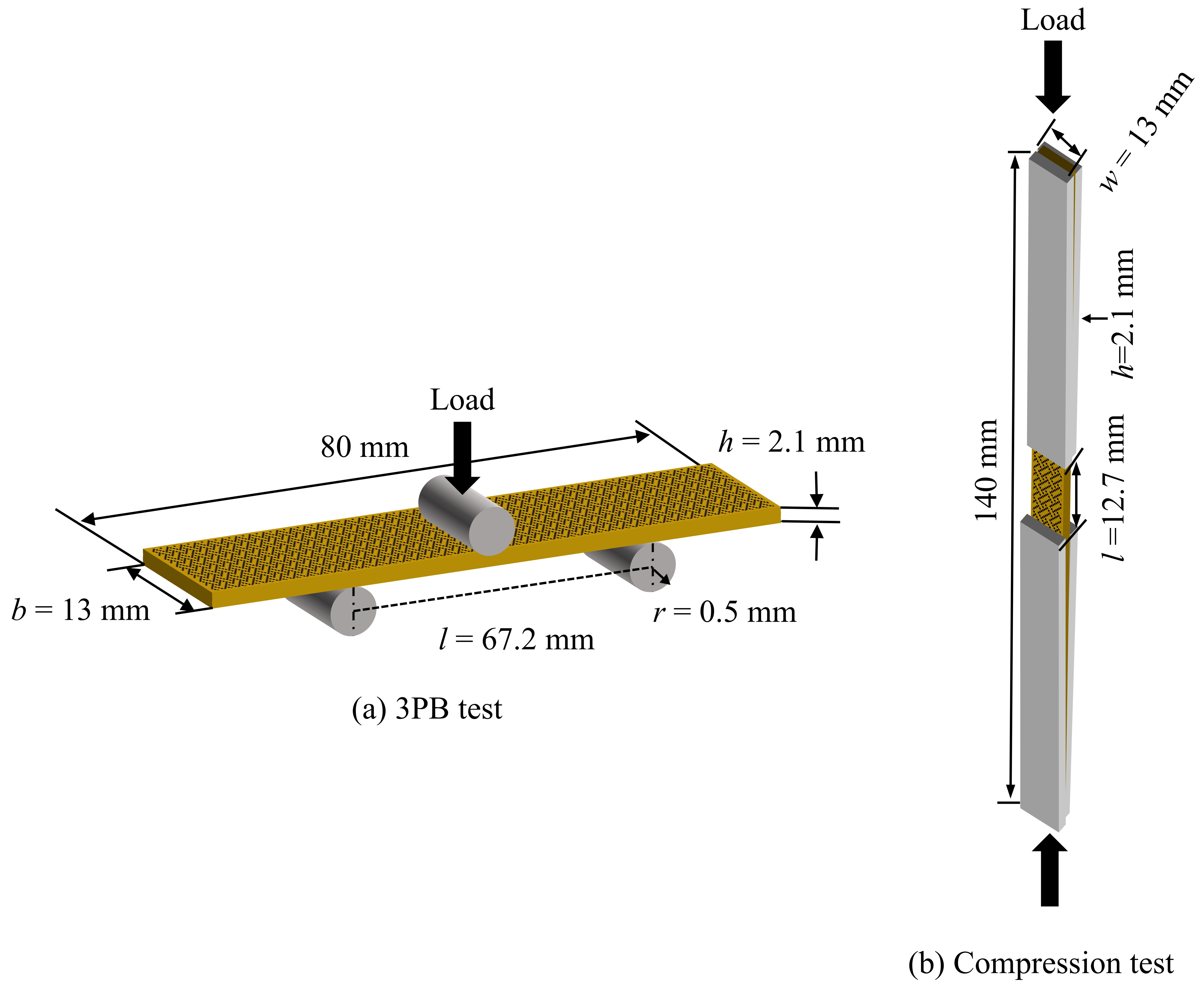
3PB tests were conducted using an MTS CMT4104 universal testing machine equipped with a 10 kN load cell. As shown in Figure 3a. The BFRP specimens were fabricated into standard dimensions specified for corresponding sizes. The support span was determined in accordance with ASTM D7264 [40]. A set of six specimens was tested for each group. The loading nose was displaced at a constant crosshead speed of 2 mm/min. The test was terminated upon a sudden drop in the load, indicating the complete failure of the specimen. The flexural stress (r) and strain (e) were calculated by Equations (1) and (2).
σ f = 3 P L 2 b h 2
ε f = 6 δ h L 2
where P is the applied force; L and δ are the support span and mid-span deflection; b and h are the width and thickness of the specimen. The span/thickness ratio was 32, with the specific thickness provided in Table 2.
The standard-sized composite material specimens with a length of 140 mm and a width of 13 mm were fabricated in accordance with the ASTM D6641 standard [41], the compression tests were performed on an ETM105D universal testing machine, as shown in Figure 3b. The tests were conducted under displacement control at a constant crosshead speed of 1 mm/min. The test was terminated automatically upon a sudden drop in the load, indicating specimen failure. The compressive strength could be calculated using Equation (3), and the modulus after compression could be calculated using Equation (4):
F c u = P f w h
E = P 3000 P 1000 ( ε 1000 ε 3000 ) A
In this equation, Fcu represents compressive strength; Pf represents compressive load force; w represents the width of the specimen; h represents the thickness of the specimen; E is the effective compressive modulus; P1000 and P3000 are the forces corresponding to 1000 and 3000 microstrains, respectively; ε1000 and ε3000 are the recorded strain values closest to 1000 and 3000 microstrains, respectively; A is the cross-sectional area.
The interfacial structure of the BFRP composites and the distribution morphology of the MNASF and ZF within the interlayer were characterized using OM (WUMO WMJ-9590, Shanghai WUMO Optical Instrument Co., Ltd., Shanghai, China). The distribution of the two fibers was examined to determine the impact on the properties of BFRP composites.
SEM (ZEISS Gemini 300, Carl Zeiss GmbH, Oberkochen, Germany) was used to observe the microstructure of the fracture surface of failed BFRP specimens and to investigate the reinforcing mechanism of MNASF and ZF at the interface.

3. Results and Discussion

3.1. Interlayer Fiber Distribution Structure

Figure 4 illustrates the interlayer structures of the unreinforced, MNASF-reinforced, and ZF-reinforced BFRP composites, as observed by OM. Figure 4a–c displayed the interlayer structure of the unreinforced BFRP composites. These images revealed a distinct sandwich structure, which consisted of a BF layer–resin layer–BF layer sequence. The major defect of this structure was found to be that it was prone to microcracks under external loading. The main reason was identified as that when BFRP composites were prepared, excessive amounts of resin were added to fully saturate the fibers, resulting in the introduction of excessive amounts of resin between the fiber interlayers and the formation of the resin-rich region. Figure 4b clearly showed that the thickness of the resin-rich region was approximately 50 µm. Due to the inherent brittleness of the resin, microcracks were easily generated under external force, and these microcracks were found to propagate along the interlayer, ultimately leading to delamination failure of BFRP [13]. Figure 4d–f presented the interlayer structure of the BFRP composites following the introduction of MNASF. In comparison with the unreinforced composites, the incorporation of MNASF into the interlayer significantly reduced the volume fraction of the resin-rich region, suppressed the initiation of microcracks, and hindered their propagation. Furthermore, direct contact was established between some MNASFs and the adjacent BF layers. These embedded MNASFs contributed to the formation of fiber bridging across the interface. These mechanisms collectively enhanced the structural stability and mechanical properties of the composite.
The interlayer structure of the ZF-reinforced BFRP composites was presented in Figure 4g–i. The incorporation of ZF also decreased the volume fraction of the resin-rich region and mitigated the inherent brittleness of the resin matrix. A fraction of the ZF became embedded within the BF layers, forming quasi-Z-directional fiber bridging between the interlayers. This reinforcement mechanism strengthened the physical connection between the fiber and resin layers, thereby suppressing the initiation and propagation of microcracks. Consequently, the efficiency of interfacial stress transfer was enhanced, which in turn prevented localized stress concentration under external loading. The two-dimensional and three-dimensional views in Figure 4f,i, illustrated the distribution patterns of the MNASF and ZF within the composite interlayer. In the two-dimensional view, the fiber cross-sections exhibited both circular and elongated oval shapes. The distinct morphologies of the MNASF and ZF observed in the interlayer indicated that the fibers were distributed in a multidirectional manner at multiple angles between the layers of the composites. These multiangle fiber distributions were conducive to the construction of fiber bridging, and at the same time made it easy for the two types of fibers to form a multi-scale fiber network structure, enhancing the interlaminar properties of BFRP composites.

3.2. Flexural Properties Analysis

The results of the 3PB tests were summarized in Table 3 and presented graphically in Figure 5. The load–displacement curves were presented in Figure 5a, while Figure 5b–d quantified the average flexural strength, flexural modulus, and energy absorption, respectively. A one-way analysis of variance (ANOVA) was conducted for each property, followed by a post hoc test, to determine statistically significant differences among the groups.
The force-displacement curves of the 3PB tests of BFRP composites incorporating MNASF and ZF are illustrated in Figure 5a. The higher the slope in the figure, the stronger the composite’s resistance to bending deformation was indicated. The figure clearly showed that the BFRP composite reinforced with 2 wt.% MNASF and 2 wt.% ZF exhibited the highest resistance to flexural deformation among all the tested samples. The average flexural strength of the BFRP composites incorporating MNASF and ZF was presented in Figure 5b. It was observed that the introduction of fibers demonstrated a highly significant and powerful effect on flexural strength (F = 78.44, p < 0.001, partial η2 = 0.929). Among them, the BFRP composites with 2 wt.% MNASF and 2 wt.% ZF performed the best, with an increase of 119.2% (95% CI = 270.14–306.84), which is higher than that reported in other published research on BFRP composites [42,43,44].
Figure 5c illustrates the average flexural modulus of BFRP specimens reinforced with MNASF and ZF at different mass ratios. A similar significant effect was observed for flexural modulus (F = 292.64, p < 0.001, partial η2 = 0.980). As detailed in Figure 5c, the BFRP composites reinforced with 4 wt.% ZF and the BFRP composites with 2 wt.% MNASF and 2 wt.% ZF exhibited the highest modulus, which was 66.6% (95% CI = 22.84–24.30) and 62.6% (95% CI = 22.18–23.72), respectively. Crucially, the post hoc analysis revealed no statistically significant difference between these two top-performing groups (p > 0.05). However, the other bending resistance properties of the BFRP composites with 2 wt.% MNASF and 2 wt.% ZF, such as bending strength and energy absorption, were significantly higher than those of BFRP composites reinforced with 4 wt.% ZF. This evidence suggested that the introduction of aramid/zirconia hybrid fiber-reinforced BFRP composites effectively combined the reinforcing effects of the two types of reinforcing fibers, resulting in a significant synergistic effect.
For energy absorption, the ratio of two fibers was again identified as a significant factor (F = 84.04, p < 0.001, partial η2 = 0.933), as shown in Figure 5d. The BFRP composites with 2 wt.% MNASF and 2 wt.% ZF demonstrated the highest energy absorption, which was 126.7% (95% CI = 0.31–0.37). The post hoc analysis confirmed that its energy absorption was statistically superior to all other groups (p < 0.05). This remarkable improvement was attributed to the unique multi-scale fiber network structure formed by the synergistic effect of MNASF and ZF. This multi-scale fiber network structure enhanced the efficiency of load transfer, impeded the propagation of microcracks, and increased the energy consumed during fiber fracture.

3.3. Compressive Properties Analysis

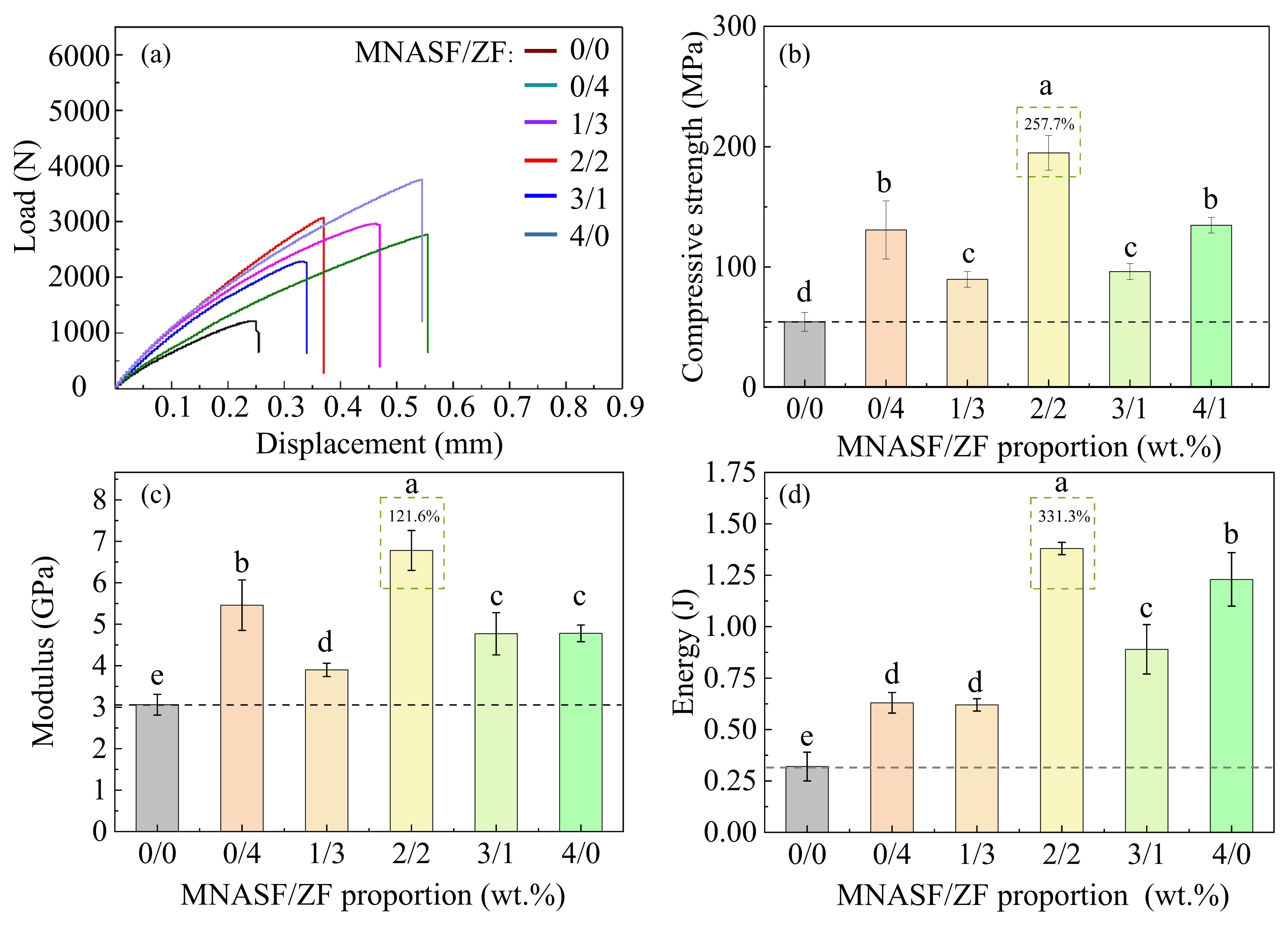
The results of the compression tests were summarized in Table 4 and graphically represented in Figure 6. The load–displacement curves of the compression tests of BFRP composites reinforced with MNASF and ZF at different mass ratios were shown in Figure 6a. The slope could be used to determine the BFRP specimen resistance to deformation under compression. The BFRP composite reinforced with a hybrid of 2 wt.% MNASF and 2 wt.% ZF exhibited the highest load bearing capacity among all tested groups. Figure 6b illustrated the average compressive strength of BFRP composites reinforced with MNASF and ZF at different mass ratios. It was observed that the introduction of fibers demonstrated a highly significant and powerful effect on compression strength (F = 71.19, p < 0.001, partial η2 = 0.937). Among them, the BFRP composites with 2 wt.% MNASF and 2 wt.% ZF achieved the best compressive strength, representing a 257.7% (95% CI = 177.01–212.77) increase over the unreinforced BFRP composites. Post hoc analysis confirmed that the compressive strength of the BFRP composites with 2 wt.% MNASF and 2 wt.% ZF was statistically superior to all other configurations (p < 0.05), as indicated by the lettering in the figure.
The introduction of MNASF and ZF with different mass ratios significantly enhanced the average compressive modulus of BFRP composites (F = 49.63, p < 0.001, partial η2 = 0.912), as illustrated in Figure 6c. Similarly to the strength results, the BFRP composites with 2 wt.% MNASF and 2 wt.% ZF demonstrated the most pronounced enhancement, achieving a 121.6% (95% CI = 6.18–7.38) increase in average compressive modulus. Post hoc analysis verified that this value was also statistically superior to all other groups (p < 0.05). As evidenced in Figure 6d, all hierarchical aramid/zirconia hybrid fiber-reinforced BFRP composites exhibited significantly higher compressive energy absorption values than the unreinforced BFRP composites (F = 119.87, p < 0.001, partial η2 = 0.961). Among these, the BFRP composites with 2 wt.% MNASF and 2 wt.% ZF demonstrated the most optimal properties, achieving a 331.3% (95% CI = 1.34–1.42) increase in energy absorption. The post hoc analysis confirmed that its energy absorption was statistically superior to all other groups (p < 0.05), further reinforcing its optimal synergistic performance under compressive loads. In summary, the incorporation of MNASF and ZF effectively enhanced the compressive properties of the BFRP composites.

3.4. Failure Model Analysis

The fracture surfaces of the BFRP specimens were photographed using OM following the 3PB tests to investigate their failure modes and fractured characteristics. Figure 7 illustrates images of the failure areas of the unreinforced BFRP composites and the hierarchical aramid/zirconia hybrid fiber-reinforced BFRP composites after 3PB tests. The crack propagation paths resulting from interlayer damage were highlighted by red and blue lines. In the unreinforced BFRP specimens, microcracks primarily propagated horizontally along the resin-rich region and the interfacial transition region, resulting in a delamination failure mode. This phenomenon demonstrated that the resin-rich region and the interfacial transition region of BFRP composites constituted weak points when subjected to external forces. In contrast, within the reinforced BFRP specimens, the crack propagation path was altered from horizontal expansion along the resin-rich region to vertical propagation through multiple BF layers. This change demonstrated that the multi-scale fiber network formed by MNASF and ZF effectively suppressed horizontal crack propagation, thereby altering the dominant failure mode of the composites. Overall, the incorporation of the two fibers led to a significant improvement in the mechanical properties of the BFRP composites.

3.5. Damaged Interlayer Microstructure of BFRP Composites with Various Masses of MNASF and ZF

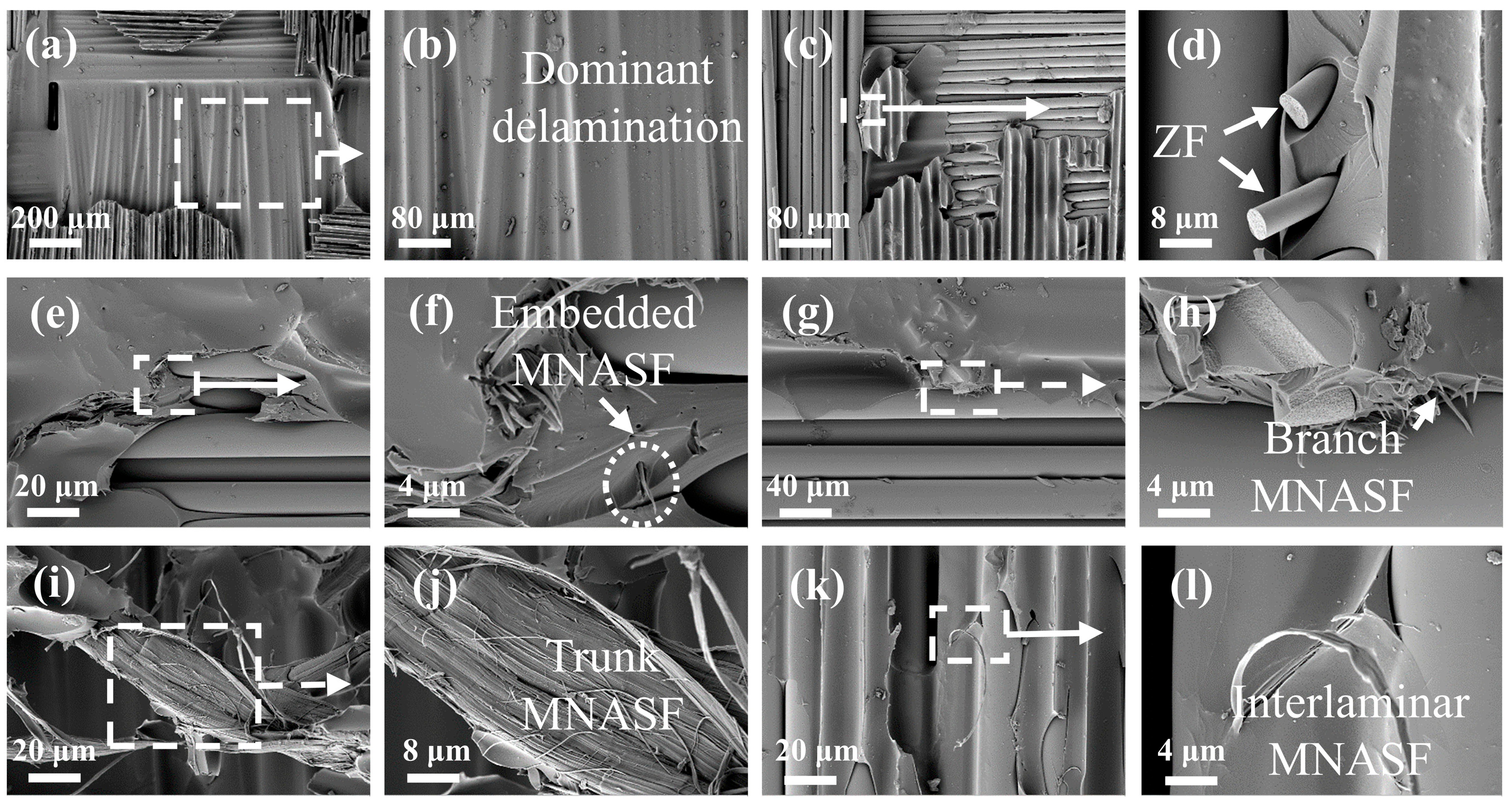
Figure 8 illustrates SEM images of the fracture surfaces for both unreinforced and hierarchical aramid/zirconia hybrid fiber-reinforced BFRP composites fabricated with different mass ratios. Figure 8a,b presents the fracture morphology of the unreinforced BFRP composites. Fracture was found to occur predominantly at the interface between the resin matrix and the fiber layers. These observations indicated that the dominant failure mode was interfacial delamination. Therefore, it was concluded that delamination in the unreinforced BFRP composites was initiated by microcracks propagating along the interlaminar plane. The fracture surface morphology of the ZF-reinforced BFRP composites was shown in Figure 8c,d. ZF could be seen embedded in the fiber layers. This confirmed that the incorporated ZF were embedded within the fiber layers, thereby enhancing stress transfer between fibers and mitigating stress concentration under external loading.
Figure 8e–l illustrates the microstructural morphology of MNASF within the fracture surfaces of BFRP composites. In Figure 8e–h, MNASF could be observed being pulled out from the resin matrix. This observation indicated that when the BFRP specimens were subjected to external loading, a portion of the energy was dissipated through the debonding and pull-out of MNASF from the matrix. Consequently, the MNASF effectively hindered the propagation of microcracks within the resin matrix. The main trunk and branches of the MNASF could be clearly observed in Figure 8i–l. Some branch fibers could be seen embedded within the BF layer, forming fiber-bridging structures between the fiber layers. These fiber-bridging structures enhanced interlayer adhesion and facilitated stress distribution and transfer, thereby effectively mitigating stress concentration. The incorporation of MNASF and ZF effectively optimized the interlayer structure of the BFRP composites, leading to a significant enhancement in mechanical properties.

3.6. Contribution of MNASF and ZF on Improving BFRP Composites

Figure 9 illustrates the proposed reinforcement mechanisms of MNASF and ZF in BFRP composites. The microstructure of the unreinforced BFRP composites was schematically illustrated in Figure 9a. It could be observed that a distinct resin-rich region existed between the fiber interlayers. Owing to the inherent brittleness of the resin, this region was highly susceptible to microcrack formation under external loading. Under continuous loading, these microcracks propagated along the interfacial transition region between the resin and fiber layers, leading to delamination failure.
Figure 9b schematically represents the reinforcement mechanism following the incorporation of MNASF and ZF into the BFRP composites. Following the introduction of MNASF and ZF, the two fibers were combined to form a multi-scale fiber network structure, thereby reducing the volume fraction of the resin-rich region. The inherent brittleness of the resin was effectively mitigated, reducing the likelihood of microcracks being formed in the resin-rich region under external stress. Simultaneously, ZF pins penetrated the resin-rich region and interfacial transition region, embedding at the BF interlayer surfaces. In parallel, the MNASF was embedded within the BF layers, establishing multidirectional mechanical anchoring points. The fiber-bridging structure formed by the two types of fibers and the multi-scale fiber network structure was able to suppress and deflect the propagation of microcracks in the resin-rich region and the interfacial transition region. These mechanisms altered the dominant failure mode of the BFRP composites, significantly reducing the propensity for delamination.

4. Conclusions

In this study, MNASF and ZF were incorporated into the interlayers of BFRP composites to form a multi-scale fiber network structure, which effectively enhanced the flexural and compressive properties of the BFRP composites. Some conclusions reached were as follows.
(1)
The introduction of MNASF and ZF effectively optimized the interlayer microstructure of the BFRP composites. The incorporation of the two fibers reduced the volume fraction of the resin-rich regions and mitigated resin brittleness, while the fibers were simultaneously embedded within the basalt fiber layers, which confirmed the fiber-bridging structure.
(2)
BFRP composites with 2 wt.% MNASF and 2 wt.% ZF content demonstrated the best properties. Compared to unreinforced BFRP composites, the reinforced BFRP composites exhibited a 119.2% increase in flexural strength and a 62.6% increase in modulus. Additionally, the compressive strength and modulus increased by 257.7% and 121.6%.
(3)
MNASF and ZF formed fiber-bridging structures between the fiber layers, and the combination of the two fibers created a multi-scale fiber network structure, which transformed microcrack propagation from horizontal expansion to vertical expansion. This caused the dominant failure mode of the BFRP composites to transition from delamination failure to shear failure.
The prepared hierarchical aramid/zirconia hybrid fiber-reinforced BFRP composites exhibited significantly enhanced properties compared to conventional BFRP composites. It has been proven that introducing two types of fibers for interlayer reinforcement was a viable reinforcement method.

Author Contributions

Conceptualization, F.C. and X.H.; Methodology, Z.Z., S.S. and R.T.; Software, E.L., D.B. and H.L.; Validation, J.H., X.Y. and P.Z.; Formal analysis, B.Y.; Investigation, Z.Z.; Resources, E.L. and H.L.; Data curation, J.H.; Writing—original draft, Z.Z.; Writing—review & editing, F.C.; Visualization, X.Y.; Supervision, X.H.; Funding acquisition, F.C. All authors have read and agreed to the published version of the manuscript.

Funding

This work was supported financially by the Natural Science Foundation of Sichuan Province, China (No. 2025HJRC0019, 2025ZNSFSC1253 and 2025ZNSFSC0844).

Institutional Review Board Statement

Not applicable.

Informed Consent Statement

Not applicable.

Data Availability Statement

Data is contained within the article.

Acknowledgments

The authors extend their gratitude from Scientific Compass (www.shiyanjia.com) for providing invaluable assistance with the SEM analysis. The authors also sincerely thank the editors and reviewers for offering revision suggestions.

Conflicts of Interest

The authors declare no conflict of interest.

References

  1. Zheng, H.; Zhang, W.J.; Li, B.W.; Zhu, J.J.; Wang, C.H.; Song, G.J.; Wu, G.S.; Yang, X.P.; Huang, Y.D.; Ma, L.C. Recent advances of interphases in carbon fiber-reinforced polymer composites: A review. Compos. Pt. B Eng. 2022, 233, 19. [Google Scholar] [CrossRef]
  2. Ni, X.C.; Furtado, C.; Kalfon-Cohen, E.; Zhou, Y.; Valdes, G.A.; Hank, T.J.; Camanho, P.P.; Wardle, B.L. Static and fatigue interlaminar shear reinforcement in aligned carbon nanotube-reinforced hierarchical advanced composites. Compos. Pt. A Appl. Sci. Manuf. 2019, 120, 106–115. [Google Scholar] [CrossRef]
  3. Zhang, J.; Lin, G.; Vaidya, U.; Wang, H. Past, present and future prospective of global carbon fibre composite developments and applications. Compos. Pt. B Eng. 2023, 250, 19. [Google Scholar] [CrossRef]
  4. Lefeuvre, A.; Garnier, S.; Jacquemin, L.; Pillain, B.; Sonnemann, G. Anticipating in-use stocks of carbon fiber reinforced polymers and related waste flows generated by the commercial aeronautical sector until 2050. Resour. Conserv. Recycl. 2017, 125, 264–272. [Google Scholar] [CrossRef]
  5. Dhand, V.; Mittal, G.; Rhee, K.Y.; Park, S.J.; Hui, D. A short review on basalt fiber reinforced polymer composites. Compos. Pt. B Eng. 2015, 73, 166–180. [Google Scholar] [CrossRef]
  6. Jagadeesh, P.; Rangappa, S.M.; Siengchin, S. Basalt fibers: An environmentally acceptable and sustainable green material for polymer composites. Constr. Build. Mater. 2024, 436, 27. [Google Scholar] [CrossRef]
  7. Lu, G.J.; Wang, W.H.; Shen, S.J. Mechanical Properties of Wood Flour Reinforced High Density Polyethylene Composites with Basalt Fibers. Mater. Sci.-Medzg. 2014, 20, 464–467. [Google Scholar] [CrossRef]
  8. Kim, S.H.; Lee, J.H.; Kim, J.W.; Lee, S.Y.; Park, S.J. Interfacial Behaviors of Basalt Fiber-Reinforced Polymeric Composites: A Short Review. Adv. Fiber Mater. 2022, 4, 1414–1433. [Google Scholar] [CrossRef]
  9. Banibayat, P.; Patnaik, A. Variability of mechanical properties of basalt fiber reinforced polymer bars manufactured by wet-layup method. Mater. Des. 2014, 56, 898–906. [Google Scholar] [CrossRef]
  10. Li, X.; Li, G.M.; Su, X.H. NanoSiO2, strengthens and toughens epoxy resin/basalt fiber composites by acting as a nano-mediator. J. Polym. Eng. 2019, 39, 10–15. [Google Scholar] [CrossRef]
  11. Alaimo, G.; Valenza, A.; Enea, D.; Fiore, V. The durability of basalt fibres reinforced polymer (BFRP) panels for cladding. Mater. Struct. 2016, 49, 2053–2064. [Google Scholar] [CrossRef]
  12. Yang, G.M.; Cheng, F.; Zuo, S.H.; Zhang, J.H.; Xu, Y.; Hu, Y.S.; Hu, X.Z.; Wei, Y.; Gou, G.J. Constructing quasi-vertical fiber bridging behaviors of aramid pulp at interlayer of laminated basalt fiber reinforced polymer composites to improve flexural performances. Chin. J. Aeronaut. 2023, 36, 477–488. [Google Scholar] [CrossRef]
  13. Hu, Y.S.; Han, G.; Cheng, F.; Hu, X.Z. Thickness effect on flexural strengths of laminar carbon fibre composites. Thin-Walled Struct. 2023, 186, 8. [Google Scholar] [CrossRef]
  14. Yoshimura, A.; Nakao, T.; Yashiro, S.; Takeda, N. Improvement on out-of-plane impact resistance of CFRP laminates due to through-the-thickness stitching. Compos. Pt. A Appl. Sci. Manuf. 2008, 39, 1370–1379. [Google Scholar] [CrossRef]
  15. Hui, C.; Wang, P.; Legrand, X. Improvement of tufting mechanism during the advanced 3-dimensional tufted composites manufacturing: To the optimisation of tufting threads degradation. Compos. Struct. 2019, 220, 423–430. [Google Scholar] [CrossRef]
  16. Huang, T.; Wang, Y.L.; Wang, G. Review of the Mechanical Properties of a 3D Woven Composite and Its Applications. Polym.-Plast. Technol. Eng. 2018, 57, 740–756. [Google Scholar] [CrossRef]
  17. Knopp, A.; Scharr, G. Effect of z-pin surface treatment on delamination and debonding properties of z-pinned composite laminates. J. Mater. Sci. 2014, 49, 1674–1683. [Google Scholar] [CrossRef]
  18. Sohn, M.-S.; Hu, X.-Z. Comparative study of dynamic and static delamination behaviour of carbon fibre/epoxy composite laminates. Composites 1995, 26, 849–858. [Google Scholar] [CrossRef]
  19. Zheng, H.; Li, Y.; Tu, H.Y. Research on interlayer properties of short fiber intercalated carbon fiber/epoxy composites. Acta Mater. Compos. Sin. 2022, 39, 3674–3683. [Google Scholar]
  20. Sathishkumar, T.P.; Naveen, J.; Satheeshkumar, S. Hybrid fiber reinforced polymer composites—A review. J. Reinf. Plast. Compos. 2014, 33, 454–471. [Google Scholar] [CrossRef]
  21. Wong, D.W.Y.; Zhang, H.; Bilotti, E.; Peijs, T. Interlaminar toughening of woven fabric carbon/epoxy composite laminates using hybrid aramid/phenoxy interleaves. Compos. Pt. A Appl. Sci. Manuf. 2017, 101, 151–159. [Google Scholar] [CrossRef]
  22. Gupta, M.K.; Srivastava, R.K. Mechanical Properties of Hybrid Fibers-Reinforced Polymer Composite: A Review. Polym.-Plast. Technol. Eng. 2016, 55, 626–642. [Google Scholar] [CrossRef]
  23. Dikshit, V.; Bhudolia, S.K.; Joshi, S.C. Multiscale Polymer Composites: A Review of the Interlaminar Fracture Toughness Improvement. Fibers 2017, 5, 38. [Google Scholar] [CrossRef]
  24. Saghafi, H.; Palazzetti, R.; Heidary, H.; Brugo, T.M.; Zucchelli, A.; Minak, G. Toughening Behavior of Carbon/Epoxy Laminates Interleaved by PSF/PVDF Composite Nanofibers. Appl. Sci.-Basel 2020, 10, 5618. [Google Scholar] [CrossRef]
  25. Li, P.; Liu, D.W.; Zhu, B.; Li, B.; Jia, X.L.; Wang, L.L.; Li, G.; Yang, X.P. Synchronous effects of multiscale reinforced and toughened CFRP composites by MWNTs-EP/PSF hybrid nanofibers with preferred orientation. Compos. Pt. A Appl. Sci. Manuf. 2015, 68, 72–80. [Google Scholar] [CrossRef]
  26. Feng, P.F.; Ma, L.C.; Wu, G.S.; Li, X.R.; Zhao, M.; Shi, L.L.; Wang, M.Y.; Wang, X.J.; Song, G.J. Establishment of multistage gradient modulus intermediate layer between fiber and matrix via designing double “rigid-flexible” structure to improve interfacial and mechanical properties of carbon fiber/resin composites. Compos. Sci. Technol. 2020, 200, 8. [Google Scholar] [CrossRef]
  27. Johnson, R.K.; Zink-Sharp, A.; Renneckar, S.H.; Glasser, W.G. Mechanical properties of wetlaid lyocell and hybrid fiber-reinforced composites with polypropylene. Compos. Part A Appl. Sci. Manuf. 2008, 39, 470–477. [Google Scholar] [CrossRef]
  28. Zhang, J.; Lin, T.; Wang, X.G. Electrospun nanofibre toughened carbon/epoxy composites: Effects of polyetherketone cardo (PEK-C) nanofibre diameter and interlayer thickness. Compos. Sci. Technol. 2010, 70, 1660–1666. [Google Scholar] [CrossRef]
  29. Bovicelli, F.; Saghafi, H.; Brugo, T.M.; Belcari, J.; Zucchelli, A.; Minak, G. On consideration the mode I fracture response of CFRP composite interleaved by composite nanofibers. In Proceedings of the 20th European Conference on Fracture (ECF), Norwegian Univ Sci Technol, Trondheim, Norway, 30 June–4 July 2014; pp. 1316–1321. [Google Scholar]
  30. Zhang, Z.S.; Fu, K.K.; Li, Y. Improved interlaminar fracture toughness of carbon fiber/epoxy composites with a multiscale cellulose fiber interlayer. Compos. Commun. 2021, 27, 6. [Google Scholar] [CrossRef]
  31. Lan, B.W.; Liu, Y.; Mo, S.; He, M.H.; Zhai, L.; Fan, L. Interlaminar Fracture Behavior of Carbon Fiber/Polyimide Composites Toughened by Interleaving Thermoplastic Polyimide Fiber Veils. Materials 2021, 14, 2695. [Google Scholar] [CrossRef]
  32. Yuan, B.Y.; Tan, B.; Hu, Y.S.; Shaw, J.; Hu, X.Z. Improving impact resistance and residual compressive strength of carbon fibre composites using un-bonded non-woven short aramid fibre veil. Compos. Pt. A Appl. Sci. Manuf. 2019, 121, 439–448. [Google Scholar] [CrossRef]
  33. Nasser, J.; Lin, J.J.; Steinke, K.; Sodano, H.A. Enhanced interfacial strength of aramid fiber reinforced composites through adsorbed aramid nanofiber coatings. Compos. Sci. Technol. 2019, 174, 125–133. [Google Scholar] [CrossRef]
  34. Yang, G.M.; Lyu, Y.N.; Cheng, F.; He, J.X.; Zuo, S.H.; Huang, W.Y.; Hu, Y.S.; Hu, X.Z.; Chen, X. A low-cost and high-strength basalt/carbon fiber reinforced polymer improved by imitating tree-root micro/nano aramid short fiber. Chin. J. Aeronaut. 2024, 37, 526–538. [Google Scholar] [CrossRef]
  35. Azizi, H.; Eslami-Farsani, R. Study of mechanical properties of basalt fibers/epoxy composites containing silane-modified nanozirconia. J. Ind. Text. 2021, 51, 649–663. [Google Scholar] [CrossRef]
  36. Xu, Z.; Wang, F.; Yin, X.; Cheng, L.D.; Yu, J.Y.; Liu, Y.T.; Ding, B. Recent advances in ZrO2 nanofibers: From structural design to emerging applications. Sci. China-Mater. 2023, 66, 421–440. [Google Scholar] [CrossRef]
  37. Jia, Y.J.; Ajayi, T.D.; Ramakrishnan, K.R.; Negi, A.; Liu, J.; Ekkad, S.; Xu, C.Y. A skin layer made of cured polysilazane and yttria stabilized zirconia for enhanced thermal protection of carbon fiber reinforced polymers (CFRPs). Surf. Coat. Technol. 2020, 404, 8. [Google Scholar] [CrossRef]
  38. Zhang, X.X.; Wang, F.; Dou, L.Y.; Cheng, X.T.; Si, Y.; Yu, J.Y.; Ding, B. Ultrastrong, Superelastic, and Lamellar Multiarch Structured ZrO2-Al2O3 Nanofibrous Aerogels with High-Temperature Resistance over 1300 °C. ACS Nano 2020, 14, 15616–15625. [Google Scholar] [CrossRef] [PubMed]
  39. He, J.X.; Lyn, Y.; Cheng, F.; Yuan, X.; Yang, G.M.; Liang, X.L.; Shi, S.Y.; Jiang, H.Y.; Hu, X.Z.; Chen, X. Flexural and flexural-after-impact strength of basalt fiber reinforced polymer improved by ultra-thin zirconia fiber/epoxy films. Compos. Pt. B Eng. 2025, 303, 14. [Google Scholar] [CrossRef]
  40. ASTM D7264; Standard Test Method for Flexural Properties of Polymer Matrix Composite Materials. ASTM International: West Conshohocken, PA, USA, 2007.
  41. ASTM D6641; Standard Test Method for Compressive Properties of Polymer Matrix Composite Materials Using a Combined Loading Compression (CLC) Test Fixture. ASTM International: West Conshohocken, PA, USA, 2012.
  42. Liu, H.; Sun, Y.; Yu, Y.; Zhang, M.; Li, L.; Ma, L. Effect of Nano-SiO2 Modification on Mechanical and Insulation Properties of Basalt Fiber Reinforced Composites. Polymers 2022, 14, 3353. [Google Scholar] [CrossRef] [PubMed]
  43. Chen, C.; Li, P.; Xiang, D.; Liu, L.; Sun, H.; Wu, Y.; Mu, M.; Wang, B.; Zhao, C.; Li, H. Study on Mechanical Properties and Acid Corrosion Resistance of Basalt Fiber/Epoxy Resin Composites Modified by Silicon Nanowires. J. Mater. Eng. Perform. 2025, 34, 22784–22794. [Google Scholar] [CrossRef]
  44. Jiang, L.; Yang, Y.H.; Sheng, J.; Li, Y.Z.; Huang, Z.Q.; Li, J.Q.; Geng, T. Effects of different nano-SiO2/silane coupling agent “rigid-flexible” hybrid interfaces on the mechanical performance of basalt fiber/epoxy composites. Polym. Compos. 2025, 46, 6956–6969. [Google Scholar] [CrossRef]
Figure 1. The microstructure of the fibers: (a) MNASF; (b) ZF.
Coatings 15 01356 g001
Figure 2. Schematic diagram of the manufacture of hierarchical aramid/zirconia hybrid fiber-reinforced BFRP composites.
Coatings 15 01356 g002
Figure 3. Schematic drawings of BFRP composites: (a) 3PB test; (b) compression test.
Coatings 15 01356 g003
Figure 4. OM images of interlayer distribution: (a,b) unreinforced BFRP composites; (d,e) MNASF-reinforced BFRP composites; (g,h) ZF-reinforced BFRP composites; (c,f,i) interlayer fiber distribution modes.
Coatings 15 01356 g004
Figure 5. 3PB testing results of unreinforced and hierarchical aramid/zirconia hybrid fiber-reinforced BFRP composites: (a) load–displacement curves; (b) average flexural strength; (c) average flexural modulus; (d) energy absorption, different letters (e.g., a, b, c) above the bars indicate statistically significant differences between groups.
Coatings 15 01356 g005
Figure 6. Compression testing result of hierarchical aramid/zirconia hybrid fiber-reinforced composites: (a) load–displacement curves; (b) average compressive strength; (c) average compressive modulus; (d) energy absorption, different letters (e.g., a, b, c) above the bars indicate statistically significant differences between groups.
Coatings 15 01356 g006
Figure 7. Crack propagation path of the BFRP specimen.
Coatings 15 01356 g007
Figure 8. SEM photographs of BFRP composite failure specimens after 3PB testing: (a,b) unreinforced BFRP composites; (c,d) ZF-reinforced BFRP composites; (el) MNASF-reinforced BFRP composites.
Coatings 15 01356 g008
Figure 9. Reinforcing mechanisms of MNASF and ZF in BFRP composites.
Coatings 15 01356 g009
Table 1. Physical properties and suppliers of major starting materials. [34].
Major Raw MaterialPhysical FormMain FeatureSupplier
Basalt fiber fabrics0°/90° woven fiberDensity 2.63–2.65 g/cm3, tensile strength 3000–4800 MPa, and modulus 91–110 GPaHaining Anjie composites Ltd., Haining, China
MNASFMicro/nano aramid short fiberDiameter 200 nm to 10 µm, tensile strength 3.5 GPa, and modulus 130 GPaHubei Jiateng Fangzhi Ltd., Xianning, China
ZFPolycrystalline refractory fiberDensity 5.6–5.9 g/cm3, melting point up to 2715 °C, tensile strength 3 GPa, modulus 100–250 GPaLaboratory preparation
Epoxy resinTransparent liquid105 epoxy resin, toxic (boiling point higher than 204 °C)West System, Ltd., Bay City, MI, USA
HardenerYellow206 slow hardener, toxic (boiling point higher than 204 °C)
AcetoneColorless liquidAR, toxic, boiling point 56 °CChengdu Kelong Chemical Ltd., Chengdu, China
Table 2. Detailed information on BFRP composites under various conditions.
Number of Specimen GroupsMass of MNASF and ZF in Mixture (wt.%)Areal Mass of MNASF in Each Interlayer (g/m2)Areal Mass of ZF in Each Interlayer (g/m2)Thickness (mm)
Plain BFRP0/0001.78
1-MNASF/ZF0/404.882.21
2-MNASF/ZF1/31.223.662.16
3-MNASF/ZF2/22.442.442.21
4-MNASF/ZF3/13.661.222.14
5-MNASF/ZF4/04.8801.98
Table 3. Detailed 3PB testing results of laminated BFRP composites with various mass proportions of MNASF and ZF at the interlayer.
MNASF Mass Proportion (wt.%)001234
ZF Mass Proportion (wt.%)043210
Flexural strength (MPa)Average131.62198.28150.62288.49156.26208.74
Standard deviation4.7924.519.7617.499.538.81
Coefficients of variation (%)3.64%12.36%13.12%6.06%6.10%4.22%
Elasticity modulus (GPa)Average14.1523.5713.8822.9513.1716.19
Standard deviation0.470.700.990.730.520.49
Coefficients of variation (%)3.322.977.133.183.953.03
Energy absorption (J)Average0.150.180.170.340.100.19
Standard deviation0.020.020.030.030.010.01
Coefficients of variation (%)13.3311.1117.658.8210.005.26
Per unit volume energy absorption (kJ/m−3)Average79.6475.7269.77140.6742.0890.32
Standard deviation10.678.3913.0112.584.385.37
Coefficients of variation (%)13.4011.0818.658.9410.415.95
Table 4. Detailed compression testing results of laminated BFRP composites with various mass proportions of MNASF and ZF at the interlayer.
MNASF Mass Proportion (wt.%)001234
ZF Mass Proportion (wt.%)043210
Compressive strength (MPa)Average54.49130.8489.75194.8996.23134.74
Standard deviation7.8524.176.5114.406.676.50
Coefficients of variation (%)14.4118.477.257.396.934.82
Elasticity modulus (GPa)Average3.065.463.906.784.774.78
Standard deviation0.250.610.160.480.510.20
Coefficients of variation (%)8.1711.174.107.0810.694.18
Energy absorption (J)Average0.320.630.621.380.891.23
Standard deviation0.070.050.030.030.120.13
Coefficients of variation (%)21.887.934.384.8413.4810.57
Per unit volume energy absorption (kJ/m−3)Average107.99165.05162.82327.04216.71312.35
Standard deviation12.6715.6318.2925.6720.9518.64
Coefficients of variation (%)11.739.4711.237.849.675.97
Disclaimer/Publisher’s Note: The statements, opinions and data contained in all publications are solely those of the individual author(s) and contributor(s) and not of MDPI and/or the editor(s). MDPI and/or the editor(s) disclaim responsibility for any injury to people or property resulting from any ideas, methods, instructions or products referred to in the content.