Article

Slurry Aluminizing of Nickel Electroless Coated Nickel-Based Superalloy

1
Laboratoire des Sciences de l’Ingénieur pour l’Environnement (LaSIE)—UMR CNRS 7356, La Rochelle University, Avenue Michel Crépeau, Cedex 1, 17042 La Rochelle, France
2
INSTM Reference Laboratory for Engineering of Surface Treatments, Department of Chemical Engineering, Materials, Environment, Sapienza University of Rome, Via Eudossiana 18, 00184 Rome, Italy
*
Author to whom correspondence should be addressed.
Coatings 2025, 15(11), 1337; https://doi.org/10.3390/coatings15111337
Submission received: 27 October 2025 / Revised: 9 November 2025 / Accepted: 14 November 2025 / Published: 17 November 2025
(This article belongs to the Section Ceramic Coatings and Engineering Technology)

Abstract

Nickel-based superalloys require protective low-activity aluminide coatings to withstand high-temperature oxidation and corrosion in turbine applications. As opposed to conventional gas processes, this study investigates the mechanisms of formation of alternative low-activity nickel aluminide coatings on the René N5 superalloy through electroless nickel pre-deposition followed by slurry aluminizing. Different thicknesses of electroless nickel layers (5, 10, 25 μm) were deposited and subsequently aluminized with varying slurry amounts (5–16 mg/cm2) under controlled heat treatments at 700–1080 °C with heating rates of 5 and 20 °C/min. Without electroless pre-deposition, high-activity coatings with refractory element precipitates formed. With electroless nickel, a precipitate-free low-activity coating developed, with thickness increasing linearly from 15 to 40 μm proportional to the initial electroless layer. An increasing slurry amount raised the overall coating thickness from 27 to 67 μm. Kirkendall porosity formed exclusively during the δ-Ni2Al3 to β-NiAl phase transformation at elevated temperature. Reducing the heating rate from 20 to 5 °C/min significantly decreased void formation by promoting more balanced Ni-Al interdiffusion. This work demonstrates that combining electroless nickel with slurry aluminizing provides an efficient route for producing low-activity coatings with controlled microstructure and minimal porosity.

1. Introduction

Nickel-based superalloys are mainly used in aircraft turbine components due to their adequate mechanical properties at elevated temperatures [1,2,3]. However, their resistance against corrosion/oxidation is limited, and thus protective aluminide coatings are often applied on the surface [4,5,6,7]. Many processes are commonly employed to elaborate protective aluminum diffusion coatings, like CVD, pack cementation, hot dipping or slurry [8]. In CVD or pack cementation, aluminizing occurs by the adsorption of an Al-containing gas precursor molecule, which is then hydrolyzed or reduced. Al atoms are finally incorporated into the bulk by solid-state diffusion. For these processes, both the microstructure and the composition are controlled by the activity of aluminum, leading to high-activity (HA) or low-activity (LA) coatings [9]. The differences in the diffusion layer are that in low-activity (LA) coatings, the aluminide grains are larger; there are fewer diffusion paths along grain boundaries; and the substrate elements, mainly chromium, titanium, tungsten, molybdenum, rhenium and hafnium, do not precipitate at the external part of the coatings. These differences contribute to an improvement in the protective properties against oxidation and corrosion and avoid the early spallation of the oxide scale. However, the heat treatment time required by gas-phase processes to obtain a low-activity coating is relatively long, and as a result, the process energy required is significant.
Alternatively, Al diffusion coatings can be obtained from slurries without activators that form very quickly because of the self-propagating high-temperature synthesis reactions occurring upon annealing at high temperatures [10,11]. As for the hot dipping process, slurry aluminide coatings typically involve high-activity (HA) coatings, and consequently, the oxidation resistance of such coatings is generally lower than that of their low-activity counterparts [12,13].
In view of improving oxidation resistance, various studies were conducted to change slurry coatings from high- to low-activity ones. For instance, Montero et al. [14] and Grégoire et al. demonstrated the formation of low-activity coatings by mixing aluminum and chromium powders, i.e., by controlling the activity in the powder mixture of the slurry [15,16]. Alternatively, a change in microstructure can also be achieved through the application of metal coatings between the slurry and the substrate. For instance, Montero et al. successfully obtained nickel aluminide coatings on P92 (iron-based alloy) by slurry-aluminizing a 10 µm thick electroplated nickel layer [17]. Indeed, nickel aluminides exhibit higher stability and oxidation resistance than iron aluminides as demonstrated in the work of Cheng and co-authors, who studied the effect of the nickel preplating (30 µm thick) of a hot-dipped aluminide formed on a steel substrate [18]. Surface modification by preplating has also been investigated on Ni-based superalloys to avoid the precipitation of refractory elements from the substrate, which are detrimental to aluminide coatings. For example, Safari et al. investigated the pack aluminizing of a preplated nickel layer (25 ± 5 µm thick) onto the Rene 80 alloy and demonstrated that the external layer of the coating is free of precipitates despite the use of high-activity aluminizing [19]. Masoumi Balashadehi et al. aluminized pure Ni and Ni-Co electrodeposited layers on a Ni-based superalloy (Hastelloy-X) and found little incorporation of the substrate elements into the coatings, in particular with the Ni electroplated layer [20,21]. Sarraf and collab. electroplated a Co coating on IN-738 prior to slurry aluminizing [22]. They found that a critical thickness of about 10 µm of the Co preplated layer was needed to obtain homogeneous Co-modified aluminide coatings and that thicker Co deposits resulted in Kirkendall porosity. However, electrodeposition is often employed to preplate the surface, even though electroless plating allows for a more uniform coating of complex geometries through chemical reactions [23]. With this in mind, Genova et al. investigated the application of up to 20 µm of Ni electroless layers on the Rene 108DS superalloy for turbine blade applications. After a pack aluminizing process, no Kirkendall porosity was observed [24] as opposed to the electroplating process [22]. Instead, the interdiffusion zone was dramatically reduced with increasing electroless thickness, leading to much greater oxidation resistance in air at 1050 °C than that for conventional pack aluminide coatings [24].
Although the mechanisms of slurry aluminization are well known, the optimization of parameters combining electroless nickel deposition followed by slurry aluminization has never been addressed in the literature. It is unknown whether the slurry process may induce Kirkendall porosity and whether such porosity can be avoided by tailoring the thickness of the coating layers and the annealing treatments or the heating rate, which is the main purpose of this work.

2. Materials and Methods

The single-crystal René N5 nickel-based superalloy was selected for this study. The nominal composition of the substrate is given in Table 1.
The samples were cut from a <001> solidified bar in coupons of 10 mm diameter and 1.5 mm thickness. Before nickel electroless deposition, N5 substrates were ground with SiC P180 paper and rinsed with deionized water and then with ethanol. The nickel electroless coatings were deposited from a bath whose composition and experimental details can be found in Ref. [25].
The Ni electroless plated samples were then aluminized with a slurry composed of 43 wt.% Al powders (2–5 µm, 99.9% purity, Hermillon, France) mixed in 57 wt.% of an aqueous binder (PVA/water with a mass ratio 1/10) [10,26]. All heat treatments were conducted under high-purity argon atmosphere (Alphagaz 1 grade from Air Liquide, Bagneux, France 99.999% purity, residual O2 < 3 ppm, H2O < 3 ppm) in a thermobalance (TGA-92, SETARAM, Caluire, France). The TGA chamber was systematically purged for 30 min at 20 mL·min−1 before each treatment to minimize oxygen contamination. The amount of slurry deposited on each sample was determined by weighing the samples before and after spraying using an analytical balance with a precision of ±0.1 mg. The amount of slurry sprayed was then calculated as the mass gain divided by the sample surface area and expressed in mg·cm−2 with the uncertainties reported in Table 2. The slurry residue left on the aluminized surface after annealing was manually grit-blasted with alumina particles (220 mesh, pressure 1 bar) in a SANDMASTER FG-94 (Tangerang, Indonesia) apparatus. Blasting was performed at the grazing angle to ensure the uniform removal of the slurry residue without damaging the underlying coating. Cross-sectional observations confirmed that this grit-blasting procedure did not cause any surface damage to the aluminide coatings.
Table 2 gathers the reference name of the samples according to the thickness of the electroless nickel layer (“Ni” in µm), then the amount of slurry deposit (“Al” in mg/cm2) followed by the letter “R” corresponding to the heating rate (in °C/min) used and finally by the letter “T” associated with the temperature of the dwell for the aluminizing heat treatment. The dwell temperatures (700 and 1080 °C) are the typical ones used in the literature depending on the activity coating [10,26]. Note that some parameters were fixed to study the specific influence of the Ni electroless thickness and of the heating ramp leading to Kirkendall porosity.
The crystalline phases of the coatings were determined by X-Ray Diffraction (XRD) using a Bruker AXS D8 Advance (Karlsruhe, Germany) set-up (Cu Kα radiation, λ= 0.15418 nm) in the symmetric θ-θ mode, from 20 to 90° (2θ). The database used to identify the phases from XRD is PDF-2 2004. The cross-sections were observed under an FEI Quanta 200F (Hillsboro, OR, USA) scanning electron microscope (SEM). Chemical analyses were conducted with an EDAX detector (Mahwah, NJ, USA) with a Si drift detector (SDD) coupled to the SEM using EDAX GENESIS software (revision 4.5).

3. Results

3.1. Nickel Electroless Layer

After two hours of the electroless deposition of Ni on the René N5 superalloy, the surface of the samples was analyzed by XRD and observed in the cross-section, as shown in Figure 1. The XRD pattern (Figure 1a) presents four peaks; the ones indexed as (111), (200) and (220) correspond to the planes of the fcc-Ni phase as also observed on similar Ni electroless coatings on the Rene 108DS substrate [27]. In contrast, the peak at 50.9° (2θ) is attributed to the René N5 substrate, which indicates that the X-rays probed the whole 20 µm thick, dense and homogeneous electroless layer (Figure 1b).

3.2. Effect of Slurry Amount

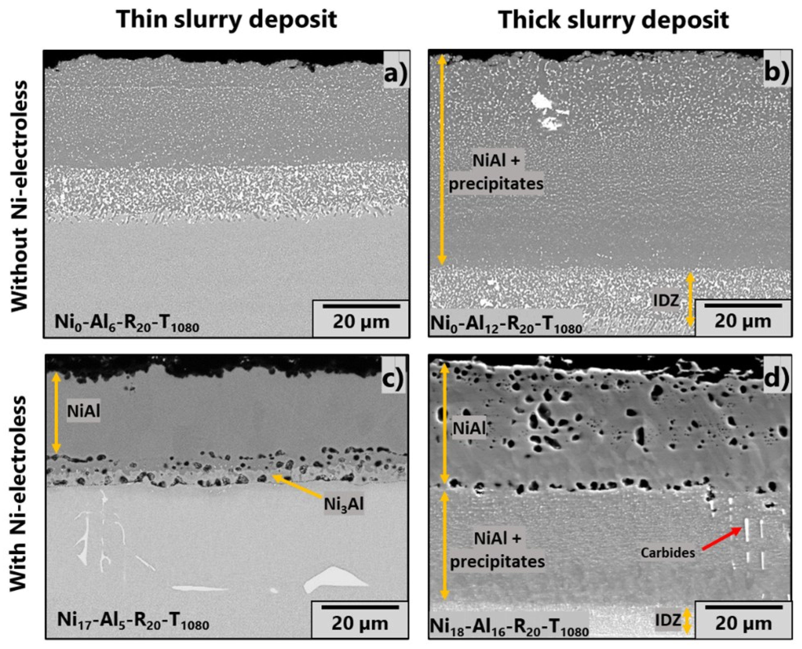
Figure 2 shows the effect of the amount of the slurry deposit (5 vs. 14 mg/cm2) on the thickness and microstructure of the coatings obtained for a similar heat treatment with and without the 18 µm thick electroless Ni pre-deposit. It can be noted that the thickness of the aluminide coatings increases with the amount of slurry deposited, for René N5 without (Figure 2a,b) or with the nickel pre-deposit (Figure 2c,d). For René N5 with the Ni electroless layer before aluminizing, the overall thickness of the coatings is around 27 µm and 67 µm for an amount of slurry deposit of 5 and 16 mg/cm2, respectively. A similar evolution in the thicknesses of the coatings is observed for the samples without the electroless deposit, which increase from 38 µm to 68 µm with a slurry deposit of 6 and 12 mg/cm2, respectively. These results are in agreement with other works investigating the influence of the slurry amount for aluminizing purposes [27,28,29] and demonstrate that the Ni electroless coatings do not appear to modify the slurry aluminizing mechanisms [17]. In contrast, the microstructure of the coatings with and without electroless coatings is quite different. Aluminizing the raw substrate (Figure 2a,b) results in a high-activity coating characterized by the presence of precipitates in a β-NiAl matrix. These precipitates appear bright due to the chemical contrast of the backscattered electrons and correspond to the refractory elements from the substrate, especially W, Ta, Mo, Re and Cr, which also form topologically close-packed (TCP) phases at the interface with the substrate [30,31,32]. Another specificity of the high-activity microstructure is that carbides from the substrate are embedded in the coatings (Figure 2b). It can be noticed that the thickness of the interdiffusion zone layer (IDZ) is similar (around 13 µm) for both the thin and thick slurry coatings on the raw N5 substrate.
In contrast to the above, the pre-deposition of a Ni electroless layer results in the formation of an external aluminide layer free of precipitates and carbides, exhibiting a microstructure similar to that of a low-activity coating [9] and of Ni or Co electroplated Ni-based alloys after pack or slurry aluminizing [17,20,22,24]. However, the microstructure of both coatings depends on the amount of slurry sprayed under the same heat treatment conditions (i.e., 1080 °C for 1 h). With a lower amount of slurry (Figure 2c), the aluminide coating consists of a main outermost layer of the β-NiAl phase and a thin layer of Ni3Al. Pores were observed at the NiAl/Ni3Al and Ni3Al/substrate interfaces. The increase in slurry amount (Figure 2d) results in the same thickness of the outermost β-NiAl layer free of precipitates than with the low-amount counterpart. However, a thick NiAl layer containing precipitates develops between the outermost NiAl layer and the substrate, and it resembles that of the precipitate-free aluminide coatings (Figure 2a,b). It thus appears that upon the saturation of the outermost NiAl layer with additional Al, the latter diffuses into the substrate, since its diffusivity is higher in the Al-rich NiAl phase, resulting in an inward-grown microstructure [9]. The row of Kirkendall pores observed between the two NiAl layers, as well as the pores distributed within the precipitate-free outermost NiAl layer, will be discussed later.

3.3. Effect of Initial Thickness of the Nickel Electroless Layer

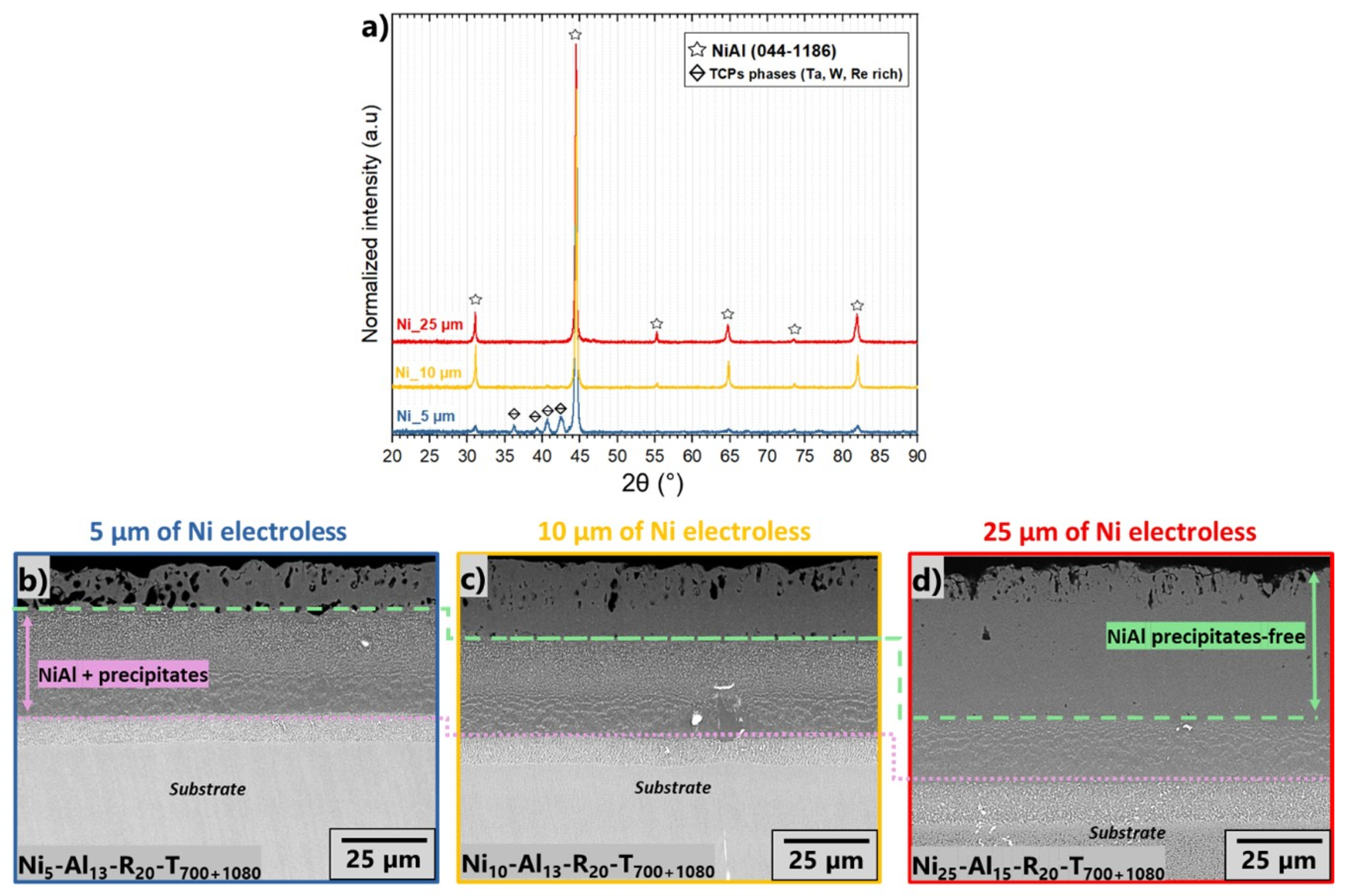
Figure 3a shows the X-ray patterns of three different thicknesses of the Ni electroless layer deposited on René N5 after aluminizing with the same quantity of slurry and the same heat treatment. The three coatings display the same peaks corresponding to the β-NiAl phase with similar intensity for coatings with 10 or 25 µm of the Ni pre-deposit. Additional peaks are identified for the coating with the thinnest Ni electroless deposit, i.e., 5 µm, which corresponds to TCP precipitates like those observed for the un-modified coatings (Figure 2).
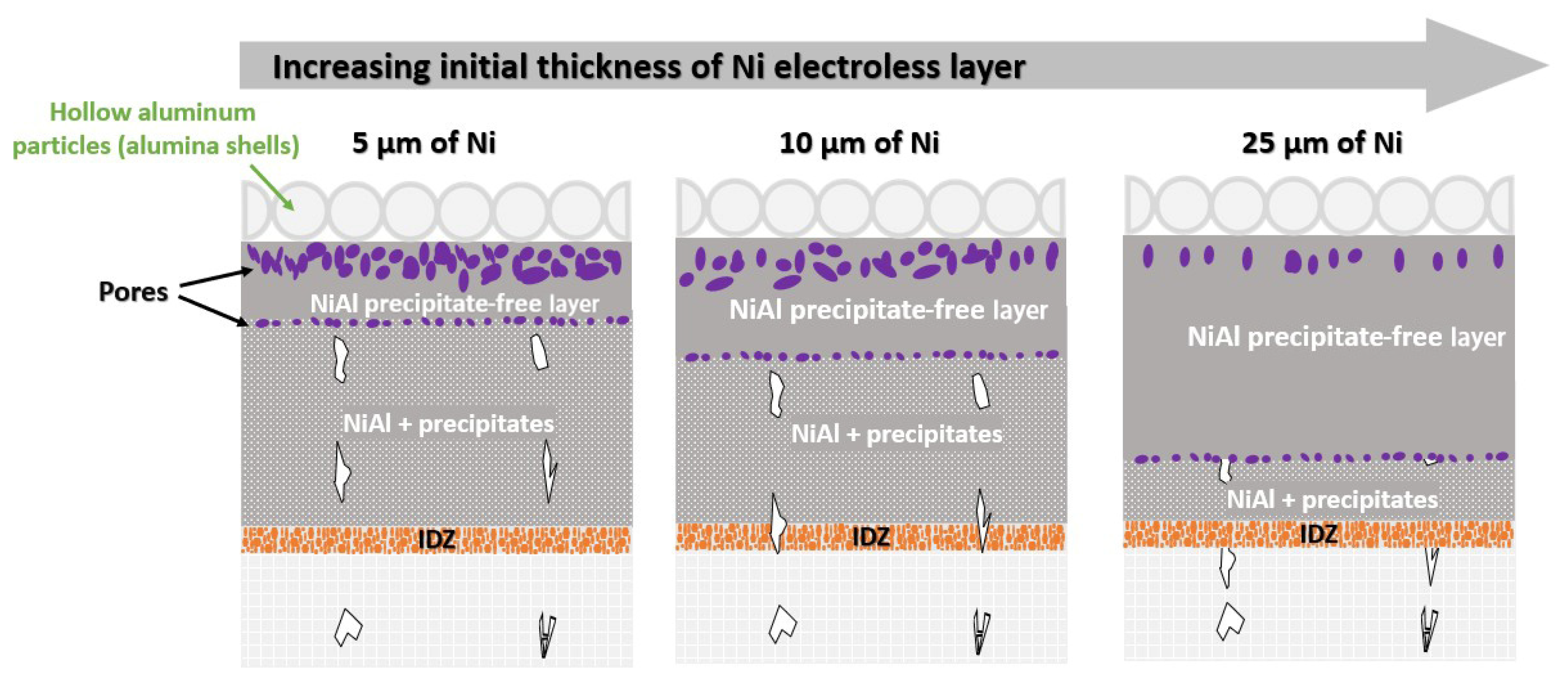
The corresponding cross-sections are gathered in Figure 3b–d. All the coatings exhibit the same microstructure consisting of an external layer of NiAl without precipitates, an intermediate layer of NiAl containing bright precipitates and an interdiffusion zone (IDZ). As the thickness of the nickel electroless layer increases, the thickness of the precipitate-free NiAl layer also increases. Conversely, the thickness of the NiAl layer with precipitates decreases. However, the thickness of the IDZ remains the same. Such observations have also been reported by Sarraf et al. on electroplated Co layers subsequently aluminized by a slurry, who attribute the outer precipitate-free zone to the direct reaction between Al and Co, while the intermediate zone appears from inward Al diffusion, and the interfacial area results from the outward diffusion of Ni [22]. It can also be noticed that the pores in all coatings are only observed within the precipitate-free layer and at the interface between this layer and the one with precipitates, as will be discussed later. In addition, the number of pores is lower with the two-step aluminizing heat treatment (700 °C/1 h + 1080 °C/1 h in Figure 3) than with a single aluminizing step (1080 °C/1.5 h in Figure 2d).

3.4. Influence of Heat Treatment

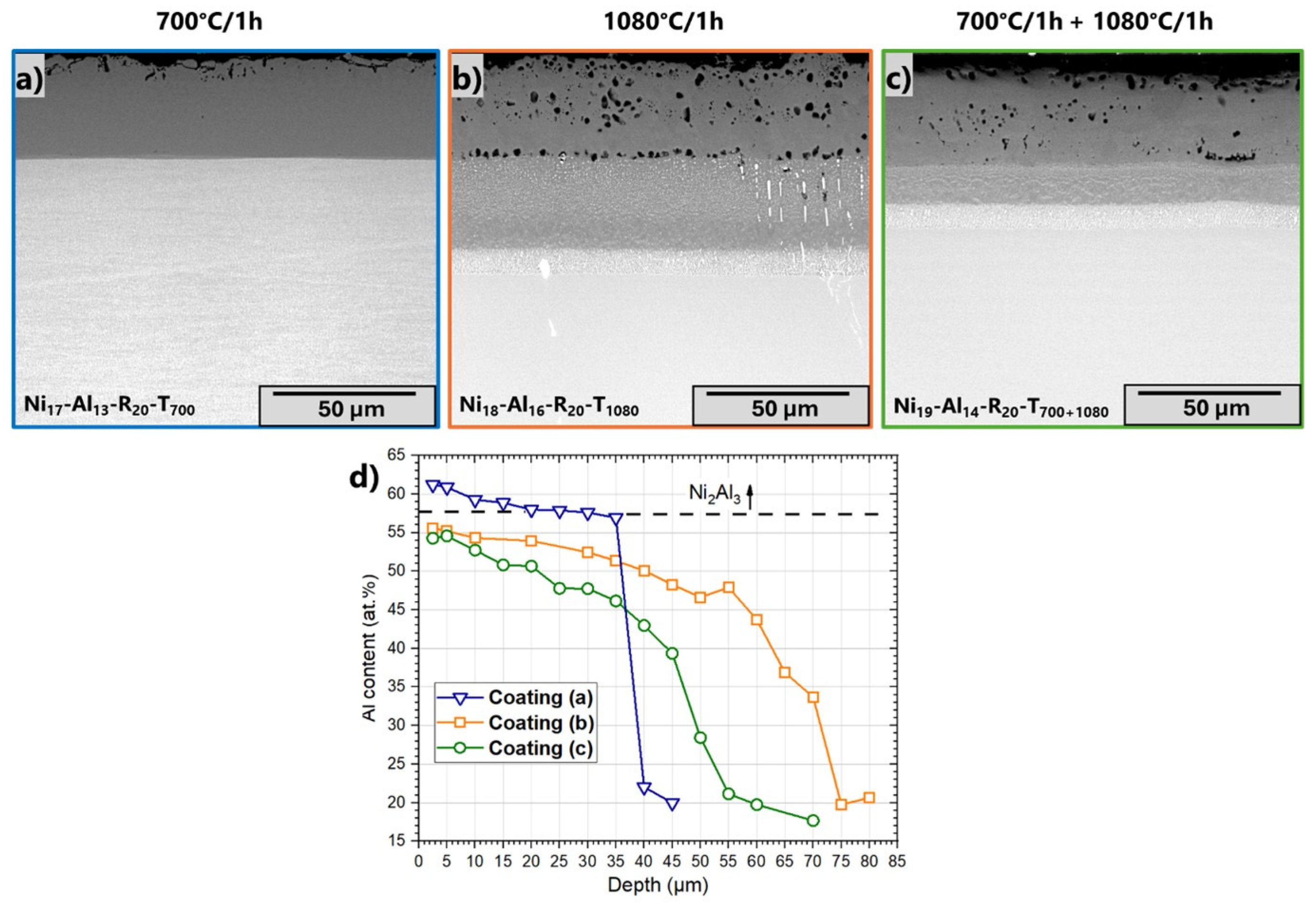
To better understand the formation of pores in the precipitate-free β-NiAl layer, aluminizing processes at both low and high temperatures were investigated. Figure 4a–c show the cross-sections of the coatings obtained after aluminizing 18 µm of the Ni electroless layer on the René N5 superalloy with 15 mg/cm2 of slurry at 700 °C for 1 h (Figure 4a), at 1080 °C for 1 h (Figure 4b) and at 700 °C/1 h and a subsequent step at 1080 °C/1 h (Figure 4c). The former presents only very few pores close to the surface of the coating compared to the two others heated up to 1080 °C. The microstructure obtained at 700 °C is completely free of precipitates and consists of a unique layer of 35 µm thick Ni2Al3 identified by XRD and confirmed by the EDS elemental analysis shown in the profile of Figure 4d.
Increasing the temperature up to 1080 °C enhances the reactivity of Al and Ni and induces diffusion and phase transformation from Ni2Al3 to β-NiAl according to the XRD (Figure 3a) and EDS measurements (Figure 4d). Interestingly, the thickness of the layer free of precipitates for the coatings formed at 1080 °C (Figure 4b,c) is the same as that obtained at 700 °C (Figure 4c). However, the interdiffusion layer growing underneath shows a different microstructure and thickness between the single step at 1080 °C and the two steps at 700 °C + 1080 °C. In the former, the interdiffusion zone is thicker, and the precipitates are finely distributed, which is very much in line with the mechanisms proposed by Sarraf et al., whereby Ni diffuses outwardly [22]. In the latter, the interdiffusion zone is thinner, and the precipitates segregate parallel to the coating, suggesting that the Ni2Al3 formed at 700 °C melts with increasing temperature [11], as will be further described later.
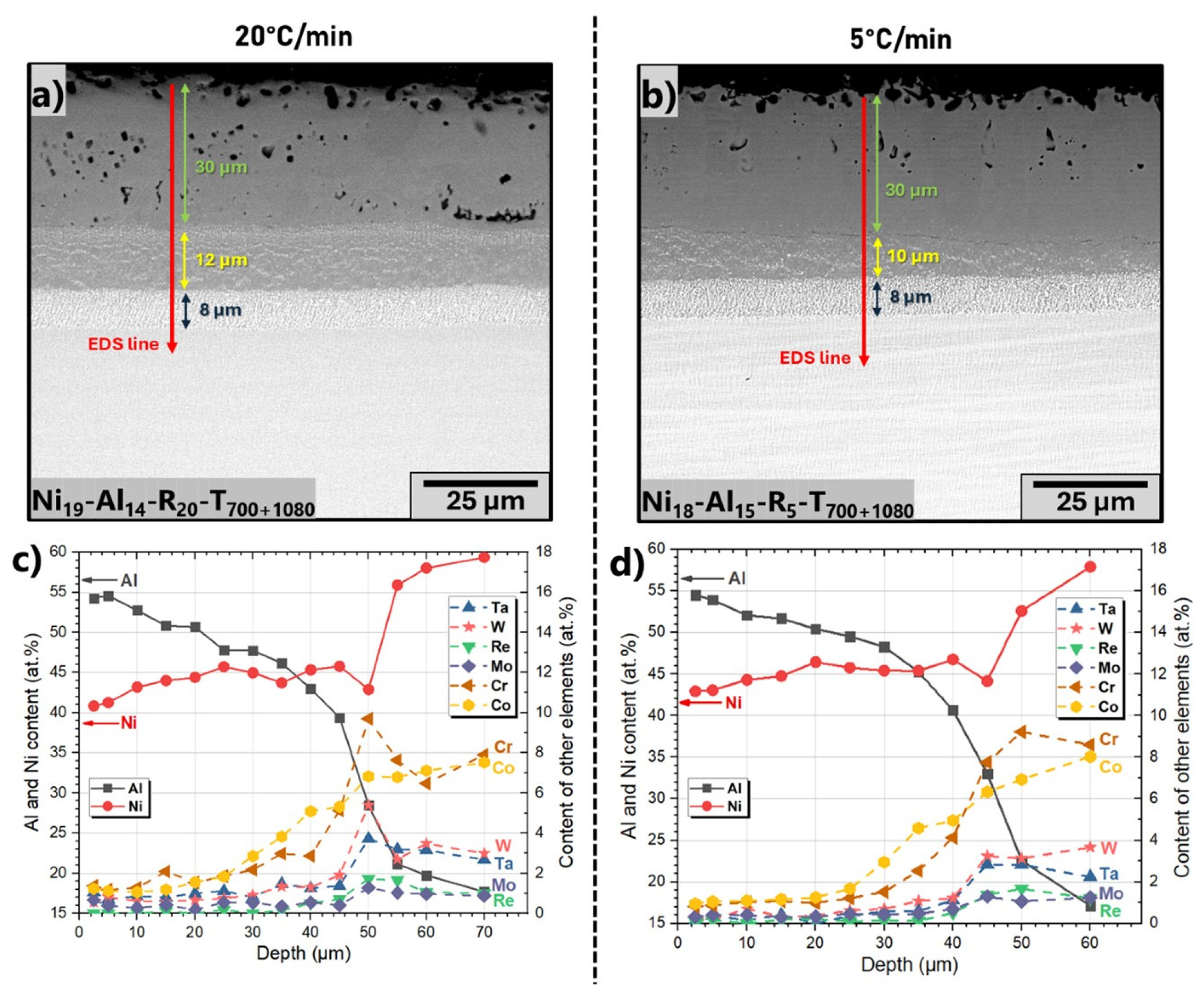
The pores observed in the precipitate-free NiAl layer are very likely Kirkendall-type, as shown in Figure 5. Indeed, reducing the heating rate from 20 to 5 °C/min, respectively, Figure 5a,b, decreases the number and size of pores. Therefore, the formation of porosity is driven by unbalanced diffusion. Figure 5c,d show the EDS diffusion profiles corresponding to Figure 5a,b, respectively. Decreasing the heating rate does not change the chemical composition of the coatings, which cover the wide range of the β-NiAl phase. Moreover, it can be noticed that in the outermost 25 µm of the coatings, the amount of each refractory element does not exceed 2 at.% (scale on the right Y axis) after aluminizing the pure nickel electroless deposit. Beyond a depth of 25 µm, both cobalt and chromium content increases, matching with the formation of the aluminide layer in the René N5 substrate. The local increase in chromium content at 50 µm in Figure 5c can be related to a TCP phase because the content of other refractory elements also increases, especially that of tungsten and of tantalum. In essence, the EDS profiles of both Al and Ni exhibit notable differences between the two heating rates in the outermost 20 µm of the coating, while the profiles of the other alloying elements (W, Re, Mo, Co, Cr and Ta) remain quite similar. Indeed, both Al and Ni display steeper concentration gradients upon heating at 20 °C/min compared to the softer slopes observed with the 5 °C/min heating ramp. This indicates that a slower heating ramp ensures more balanced interdiffusion between Ni and Al, resulting in more gradual compositional transitions.

4. Discussion

The mechanisms of slurry aluminizing without activators have already been described for bulk pure nickel and Ni-based superalloys [10,26,33,34]. It was demonstrated that once the melting point of Al is reached, the dissolution of Ni generates an exothermic reaction, called combustion or self-propagating high-temperature synthesis [35,36,37]. The first intermetallic compound formed by the reaction between Ni and molten Al is NiAl3 according to the Al-Ni binary diagram [38].
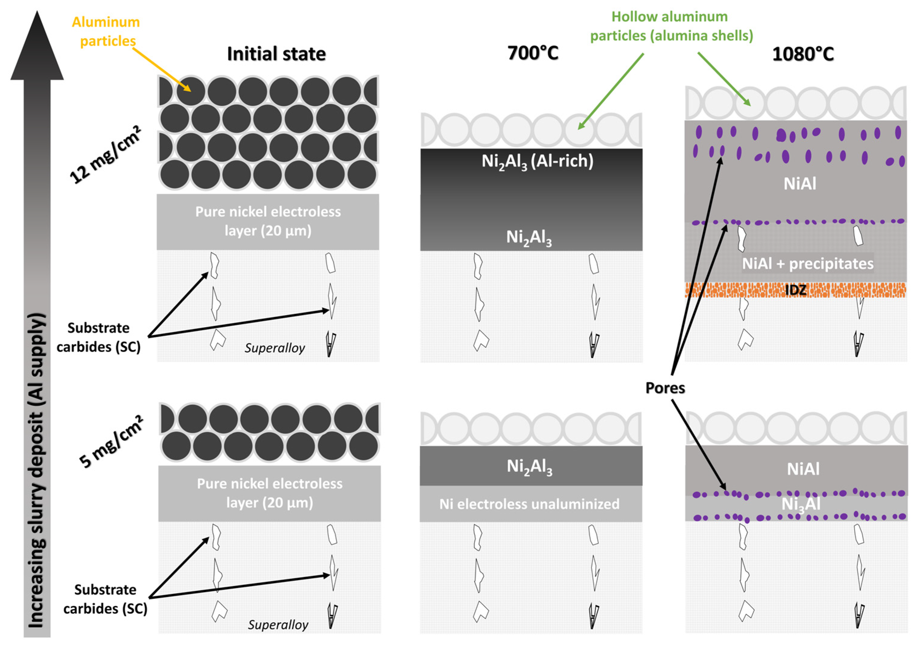
Figure 6 schematically illustrates the different mechanisms proposed as a function of aluminum activity, which depends on the amount of slurry sprayed, which is the limiting reagent. In the case of a low slurry amount (5 mg/cm2), the thickness of the electroless layer is higher than that of aluminum, making aluminum powder the limiting reagent. Once all aluminum has reacted to form the NiAl3 phase, the evolution of the coating is controlled by solid-state diffusion. Because of the chemical potential gradient, two diffusion fronts are established. Aluminum diffuses to the substrate (inward diffusion), while nickel diffuses to the surface (outward diffusion). As the amount of aluminum is limited, nickel diffusion predominates, leading to the very rapid formation of the Ni2Al3 phase. Subsequently, increasing the temperature promotes nickel outward diffusion, and the coating composition evolves towards a precipitate-free β-NiAl phase. As the diffusion rate of nickel from the unreacted nickel deposit is faster than that of aluminum from the coating [39], Kirkendall-type porosity appears at the interface due to the unbalanced flow of outward Ni atoms.
For a higher slurry amount, e.g., 12 mg/cm2, the electroless nickel now becomes the limiting reagent. In this case, the amount of aluminum is sufficiently high to react with the overall thickness of nickel. At 700 °C, the coating consists of the δ-Ni2Al3 phase with a chemical gradient of Al, the higher content being at the surface. In contrast to the previous case, the Al content remains high, and Al diffuses inwardly towards the superalloy, with which it reacts to form nickel aluminides and the refractory element precipitates. The porosity observed at the NiAl/(NiAl + precipitates) interface most likely corresponds to the original interface between the nickel deposit and the substrate, whereas the pores observed in the precipitate-free NiAl coating result from the difference in Al and Ni diffusion rates leading to Kirkendall porosity [40,41,42,43].
Kirkendall porosity is frequently observed in Ni-Al diffusion couples [42,44] or in the case of the aluminization of pure nickel [34,45,46]. Since few pores form in the Ni2Al3 phase, they are necessarily formed during the δ-Ni2Al3 → β-NiAl transition. The β structure consists of two simple cubic sub-lattices, that of Al and that of Ni. However, the range of existence of the β-NiAl phase and different atomic arrangements are observed as a function of the deviation from stoichiometry [47]. In the over-stoichiometric condition, nickel vacancies are present, whereas in the under-stoichiometric condition, nickel is located in the anti-site (in the Al sub-lattice). The intrinsic diffusion of Al and Ni varies according to stoichiometry [48,49,50]. A pronounced difference is observed in the Al-rich NiAl phase, which exhibits a much greater intrinsic diffusion of Al than Ni [50], generating a higher concentration of vacancies [51]. As a result, increasing the heating rate (between 700 and 1080 °C) accelerates Al diffusion, which generates numerous vacancies that the counterdiffusion of Ni cannot balance. The accumulation of these vacancies is at the origin of the significant porosity observed in our case and explains why the number of pores decreases with the heating ramp at 5 °C/min (Figure 5).
Figure 7 schematically shows the evolution of the microstructures of the aluminide coatings depending on the initial thickness of the Ni electroless layer. The drawing corresponds to the results described in Figure 3. The final thickness of the NiAl layer without precipitates (outermost zone) increases linearly with the initial nickel thickness, as demonstrated in Figure 8. The results obtained for the Ni electroless layer aluminized by the slurry are in agreement with those of Tan et al. [52] and Safari et al. [19], in which Ni electroplated deposits were aluminized by a high-activity pack cementation process. These authors attributed the change in thickness to the volume expansion induced by the incorporation of Al into Ni, accompanied by the formation of intermetallic phases such as δ-Ni2Al3. Since the Al amount is fixed in our case by the amount of slurry deposited, the increase in the thickness of the precipitate-free NiAl coating occurs at the expense of the precipitate-containing NiAl phase, whose thickness decreases.

5. Conclusions

This study showed that applying a nickel electroless pre-layer enables the formation of low-activity nickel aluminide coatings on nickel-based superalloys using a water-based slurry. The nickel electroless layer promotes a precipitate-free aluminide structure, while its absence leads to high-activity coatings characterized by refractory element precipitates in the aluminide layer.
The thickness of the precipitate-free NiAl layer increases linearly with the initial thickness of the nickel electroless (5, 10, 25 μm), which is attributed to the volumetric change from Ni to the δ-Ni2Al3 phase. Adjustments in the thickness of the nickel electroless pre-deposit and the quantity of slurry allow us to control the overall coating thickness.
Kirkendall porosity was identified as occurring only upon the δ-Ni2Al3 to β-NiAl phase transformation. This porosity is known to result from unbalanced interdiffusion, with Al diffusing faster than Ni in Al-rich NiAl. The results demonstrate that reducing the heating rate from 20 to 5 °C/min significantly decreases void formation. The slower heating rate ensures more balanced interdiffusion between Ni and Al, as evidenced by softer compositional gradients in the outermost coating region.

Author Contributions

Conceptualization, T.K., V.G. and F.P.; methodology, T.K., V.G. and F.P.; validation, T.K., G.B., G.P. (Giulia Pedrizzetti), V.G., G.P. (Giovanni Pulci), C.B. and F.P.; formal analysis, T.K., V.G. and F.P.; investigation, T.K., G.P. (Giulia Pedrizzetti), V.G. and F.P.; resources, F.P.; data curation, T.K.; writing—original draft preparation, T.K.; writing—review and editing, T.K., G.B., G.P. (Giulia Pedrizzetti), V.G., G.P. (Giovanni Pulci), C.B. and F.P.; visualization, T.K. and F.P.; supervision, G.B. and F.P.; project administration, F.P.; funding acquisition, F.P. All authors have read and agreed to the published version of the manuscript.

Funding

This research received no external funding.

Institutional Review Board Statement

Not applicable.

Informed Consent Statement

Not applicable.

Data Availability Statement

Data will be made available on request.

Acknowledgments

We sincerely thank Safran Aircraft Engines (M. Mondet) for supplying the investigation substrates and partially funding this work.

Conflicts of Interest

All the authors of this paper hereby declare no conflicts of interest.

Abbreviations

The following abbreviations are used in this manuscript:
CVDChemical vapor deposition
IDZInterdiffusion zone
TCPTopologically close-packed phases

References

  1. Sims, C.T.; Stoloff, N.S.; Hagel, W.C. Superalloys II; John Wiley & Sons: New York, NY, USA, 1987. [Google Scholar]
  2. Reed, R.C. The Superalloys: Fundamentals and Applications; Cambridge University Press: New York, NY, USA, 2006. [Google Scholar]
  3. Cailletaud, G.; Eggeler, G.; Nazé, L.; Cormier, J.; Maurel, V. Nickel Base Single Crystals Across Length Scales; Elsevier: Amsterdam, The Netherlands, 2021. [Google Scholar]
  4. Mevrel, R.; Pichoir, R. Les revêtements par diffusion. Mater. Sci. Eng. 1987, 88, 1–9. [Google Scholar] [CrossRef]
  5. Patnaik, P.C. Intermetallic coatings for high temperature applications—A review. Mater. Manuf. Proc. 1989, 4, 133–152. [Google Scholar] [CrossRef]
  6. Goward, G.W. Progress in coatings for gas turbine airfoils. Surf. Coat. Technol. 1998, 108–109, 73–79. [Google Scholar] [CrossRef]
  7. Caron, P.; Khan, T. Evolution of Ni-based superalloys for single crystal gas turbine blade applications. Aerosp. Sci. Technol. 1999, 3, 513–523. [Google Scholar] [CrossRef]
  8. Galetz, M.C. Coatings for Superalloys. In Superalloys; Aliofkhazraei, M., Ed.; InTech: London, UK, 2015. [Google Scholar] [CrossRef]
  9. Goward, G.W.; Boone, D.H. Mechanisms of formation of diffusion aluminide coatings on nickel-base superalloys. Oxid. Met. 1971, 3, 475–495. [Google Scholar] [CrossRef]
  10. Bonnet, G.; Mollard, M.; Rannou, B.; Balmain, J.; Pedraza, F.; Montero, X.; Galetz, M.; Schütze, M. Initial aluminizing steps of pure nickel from Al micro-particles. Defect Diff. Forum 2012, 323–325, 381–386. [Google Scholar] [CrossRef]
  11. Montero, X.; Demler, I.; Kuznetsov, V.; Galetz, M.C. Factors governing slurry aluminization of steels. Surf. Coat. Technol. 2017, 309, 179–186. [Google Scholar] [CrossRef]
  12. Nicholls, J.R. Designing oxidation-resistant coatings. JOM 2000, 52, 28–35. [Google Scholar] [CrossRef]
  13. Angenete, J.; Stiller, K. Comparison of inward and outward grown Pt modified aluminide diffusion coatings on a Ni based single crystal superalloy. Surf. Coat. Technol. 2002, 150, 107–118. [Google Scholar] [CrossRef]
  14. Montero, X.; Galetz, M.C.; Schütze, M. Low-activity aluminide coatings for superalloys using a slurry process free of halide activators and chromates. Surf. Coat. Technol. 2013, 222, 9–14. [Google Scholar] [CrossRef]
  15. Grégoire, B.; Bonnet, G.; Pedraza, F. Reactivity of Al-Cr microparticles for aluminizing purposes. Intermetallics 2017, 81, 80–89. [Google Scholar] [CrossRef]
  16. Grégoire, B.; Bonnet, G.; Pedraza, F. Mechanisms of formation of slurry aluminide coatings from Al and Cr microparticles. Surf. Coat. Technol. 2019, 359, 323–333. [Google Scholar] [CrossRef]
  17. Montero, X.; Galetz, M.C.; Schütze, M. Slurry coated Ni-plated Fe-base alloys: Investigation of the influence of powder and substrate composition on interdiffusional and structural degradation of aluminides. Surf. Coat. Technol. 2013, 236, 465–475. [Google Scholar] [CrossRef]
  18. Cheng, W.-J.; Liao, Y.-J.; Wang, C.-J. Effect of nickel pre-plating on high-temperature oxidation behavior of hot-dipped aluminide mild steel. Mater. Charact. 2013, 82, 58–65. [Google Scholar] [CrossRef]
  19. Safari, M.; Shahriari Nogorani, F. Formation mechanism of high activity aluminide coating on Ni-CeO2 coated Rene 80 alloy. Surf. Coat. Technol. 2017, 329, 218–223. [Google Scholar] [CrossRef]
  20. Masoumi Balashadehi, M.; Nourpour, P.; Sabour Rouh Aghdam, A.; Allahyarzadeh, M.H.; Heydarzadeh, A.; Hamdi, M. The formation, microstructure and hot corrosion behaviour of slurry aluminide coating modified by Ni/Ni-Co electrodeposited layer on Ni-base superalloy. Surf. Coat. Technol. 2020, 402, 126283. [Google Scholar] [CrossRef]
  21. Zakeri, A.; Masoumi Balashadehi, M.R.; Sabour Rouh Aghdam, A. Development of hybrid electrodeposition/slurry diffusion aluminide coatings on Ni-based superalloy with enhanced hot corrosion, resistance. J. Compos. Cmpd. 2021, 3, 14115–14143. [Google Scholar] [CrossRef]
  22. Sarraf, S.; Rastegari, S.; Soltanieh, M. Deposition of a low-activity type cobalt-modified aluminide coating by slurry aluminizing of a pre-Co-electroplated Ni-based superalloy, (IN738LC). J. Mater. Res. Technol. 2024, 30, 183–1193. [Google Scholar] [CrossRef]
  23. Delaunois, F.; Vitry, V.; Bonin, L. (Eds.) Electroless Nickel Plating: Fundamentals to Applications; CRC Press: Boca Raton, FL, USA, 2019. [Google Scholar] [CrossRef]
  24. Genova, V.; Pedrizzetti, G.; Paglia, L.; Marra, F.; Bartuli, C.; Pulci, G. Diffusion aluminide coating modified via electroless nickel plating for Ni-based superalloy protection. Surf. Coat. Technol. 2022, 439, 128452. [Google Scholar] [CrossRef]
  25. Genova, V.; Paglia, L.; Marra, F.; Bartuli, C.; Pulci, G. Pure thick nickel coating obtained by electroless plating: Surface characterization and wetting properties. Surf. Coat. Technol. 2019, 357, 595–603. [Google Scholar] [CrossRef]
  26. Rannou, B.; Mollard, M.; Bouchaud, B.; Balmain, J.; Bonnet, G.; Kolarik, V.; Pedraza, F. On the influence of a heat treat for an aluminizing process based on Al microparticles slurry for model Ni and Ni20Cr. Experimental and theoretical approaches. Defect Diff. Forum 2012, 323–325, 373–379. [Google Scholar] [CrossRef]
  27. Bermejo Sanz, J.; Roussel García, R.; Kolarik, V.; Juez Lorenzo, M.M. Influence of the slurry thickness and heat treatment parameters on the formation of aluminium diffusion coating. Oxid. Met. 2017, 88, 179–190. [Google Scholar] [CrossRef]
  28. Li, Z.; Wang, C.; Ding, X.; Li, X.; Yu, J.; Li, Q.; Qu, Y. Effect of slurry thickness on the quality of aluminized coatings. Materials 2022, 15, 6758. [Google Scholar] [CrossRef] [PubMed]
  29. Rae, C.M.F.; Hook, M.S.; Reed, R.C. The effect of TCP morphology on the development of aluminide coated superalloys. Mater. Sci. Eng. A 2005, 396, 231–239. [Google Scholar] [CrossRef]
  30. Matuszewski, K.; Rettig, R.; Rasiński, M.; Kurzydłowski, K.J.; Singer, R.F. The three-dimensional morphology of topologically close packed phases in a high rhenium containing nickel-based superalloy. Adv. Eng. Mater. 2014, 16, 171–175. [Google Scholar] [CrossRef]
  31. Wilson, A.S.; Christofidou, K.A.; Evans, A.; Hardy, M.C.; Stone, H.J. Comparison of methods for quantification of topologically close-packed phases in Ni-based superalloys. Metall. Mater. Trans. A 2019, 50, 5925–5934. [Google Scholar] [CrossRef]
  32. Mehrer, H.; Divinski, S. Diffusion in Metallic Elements and Intermetallics. Defect Diff. Forum 2009, 289–292, 15–38. [Google Scholar] [CrossRef]
  33. Rasmussen, A.J.; Agüero, A.; Gutierrez, M.; Østergård, M.J.L. Microstructures of thin and thick slurry aluminide coatings on Inconel 690. Surf. Coat. Technol. 2008, 202, 1479–1485. [Google Scholar] [CrossRef]
  34. Kepa, T.; Pedraza, F.; Rouillard, F. Intermetallic formation of Al-Fe and Al-Ni phases by ultrafast slurry aluminization (flash aluminizing). Surf. Coat. Technol. 2020, 397, 126011. [Google Scholar] [CrossRef]
  35. Deevi, S.C.; Sikka, V.K. Nickel and iron aluminides: An overview on properties, processing, and applications. Intermetallics 1996, 4, 357–375. [Google Scholar] [CrossRef]
  36. Gedevanishvili, S.; Deevi, S.C. Processing of iron aluminides by pressureless sintering through Fe+Al elemental route. Mater. Sci. Eng. A 2002, 325, 163–176. [Google Scholar] [CrossRef]
  37. Siemiaszko, D.; Mościcki, R. Kinetics study on the SHSreaction in massive samples with high heating rate in the Fe–Al, system. J. Alloys Compd. 2015, 632, 335–342. [Google Scholar] [CrossRef]
  38. Okamoto, H. Al-Ni (aluminium-nickel). J. Phase Equilib Diffus. 2004, 25, 394. [Google Scholar] [CrossRef]
  39. Brossard, J.M.; Panicaud, B.; Balmain, J.; Bonnet, G. Modelling of aluminized coating growth on nickel. Acta Mater. 2007, 55, 6586–6595. [Google Scholar] [CrossRef]
  40. Seitz, F. On the porosity observed in the Kirkendall effect. Acta Metall. 1953, 1, 355–369. [Google Scholar] [CrossRef]
  41. Paul, A. The Kirkendall Effect in Solid State Diffusion. Ph.D. Thesis, Technische Universiteit Eindhoven, Eindhoven, The Netherlands, 2004. [Google Scholar] [CrossRef]
  42. Mehrer, H. Diffusion in Solids; Springer: Berlin/Heidelberg, Germany, 2007. [Google Scholar] [CrossRef]
  43. Pieraggi, B. Diffusion and solid state reactions. In Developments in High Temperature Corrosion and Protection of Materials; Series in Metals and Surface Engineering; Woodhead Publishing: London, UK, 2008; pp. 9–35. [Google Scholar] [CrossRef]
  44. Janssen, M.M.P. Diffusion in the nickel-rich part of the Ni-Al system at 1000 °C to 1300 °C; Ni3Al layer growth; diffusion coefficients, and interface concentrations. Metall. Trans. 1973, 4, 1623–1633. [Google Scholar] [CrossRef]
  45. Thevand, A.; Poize, S.; Crousier, J.-P.; Streiff, R. Aluminization of nickel-formation of intermetallic phases Ni2Al3, coatings. J. Mater. Sci. 1981, 16, 2467–2479. [Google Scholar] [CrossRef]
  46. Shiomi, S.; Miyake, M.; Hirato, T.; Sato, A. Aluminide coatings fabricated on nickel by aluminium electrodeposition from DMSO2 based electrolyte and subsequent annealing. Mater. Trans. 2011, 52, 1216–1221. [Google Scholar] [CrossRef]
  47. Kogachi, M.; Haraguchi, T. Point defects in B2-type intermetallic compounds. Mater. Sci. Eng. A 2001, 312, 189–195. [Google Scholar] [CrossRef]
  48. Frank, S.; Divinski, S.V.; Södervall, U.; Herzig, C. Ni tracer diffusion in the B2-compound NiAl: Influence of temperature and composition. Acta Mater. 2001, 49, 1399–1411. [Google Scholar] [CrossRef]
  49. Divinski, S.V.; Herzig, C. Ni tracer self-diffusion, interdiffusion and diffusion mechanisms in NiAl. Defect Diff. Forum 2002, 203–205, 177–192. [Google Scholar] [CrossRef]
  50. Paul, A.; Kodentsov, A.A.; van Loo, F.J.J. On diffusion in the β-NiAl, phase. J. Alloys Compd. 2005, 403, 147–153. [Google Scholar] [CrossRef]
  51. Chang, Y.A.; Neumann, J.P. Thermodynamics and defect structure of intermetallic phases with the B2 (CsCl) structure. Prog. Solid State Chem. 1982, 14, 221–301. [Google Scholar] [CrossRef]
  52. Tan, X.; Peng, X.; Wang, F. The mechanism for self-formation of a CeO2 diffusion barrier layer in an aluminide coating at high temperature. Surf. Coat. Technol. 2013, 224, 62–70. [Google Scholar] [CrossRef]
Figure 1. (a) X-ray pattern of pure Ni electroless layer after 2 h of deposition on René N5 superalloy and (b) the associated cross-section SEM image (BSE). The yellow line shows the initial surface of the substrate.
Coatings 15 01337 g001
Figure 2. Cross-section SEM images (BSE) of coatings obtained after aluminization at 1080 °C of René N5 superalloy without (a,b) and with (c,d) pre-deposit of 18 ± 1 µm electroless nickel layer for 5 ± 1 mg/cm2 (a,c) and 14 ± 2 mg/cm2 (b,d) of slurry sprayed.
Coatings 15 01337 g002
Figure 3. (a) X-ray patterns after slurry-aluminizing three different thicknesses of Ni electroless layers on René N5 and corresponding SEM cross-sections (BSE mode): (b) 5 µm of Ni, (c) 10 µm of Ni and (d) 25 µm of Ni. N.B.: Amount of slurry is fixed at 14 ± 2 mg/cm2, and heat treatment consists of double steps at 700 and 1080 °C for 1 h each with heating rate at 20 °C/min.
Coatings 15 01337 g003
Figure 4. Cross-section SEM images (BSE) of coatings obtained after aluminizing (15 ± 2 mg/cm2 of slurry) of electroless nickel pre-deposit of 18 ± 1 µm on René N5 superalloy with different heat treatments, (a) 700 °C/1 h, (b) 1080 °C/1 h and (c) 700 °C/1 h + 1080 °C/1 h, and (d) corresponding EDS diffusion profiles of Al. N.B.: Heating rate is fixed at 20 °C/min.
Coatings 15 01337 g004
Figure 5. Cross-section SEM images (BSE) of coatings obtained after aluminization (14 ± 1 mg/cm2 of slurry) of electroless nickel pre-deposit of 18 ± 1 µm deposited on René N5 superalloy with heat treatment comprising first stage at 700 °C/1 h and second stage at 1080 °C/1 h for heating ramp of (a) 20 °C/min and (b) 5 °C/min. (c,d) represent EDS diffusion profiles corresponding to (a,b), respectively.
Coatings 15 01337 g005
Figure 6. Mechanisms of formation of coatings modified by nickel electroless pre-deposit as function of quantity of slurry deposited (5 and 12 mg/cm2) and temperatures of heat treatment with heating rate of 20 °C/min.
Coatings 15 01337 g006
Figure 7. Mechanisms of formation of coatings as function of initial thickness of Ni electroless layer. Note: The amount of slurry is fixed at 14 ± 1 mg/cm2, and heat treatment consists of two steps at 700 and 1080 °C for 1 h each with rate of 20 °C/min.
Coatings 15 01337 g007
Figure 8. Evolution of thickness of NiAl precipitate-free layer as function of initial thickness of Ni deposited. The works of Safari et al. [19] and of Tan et al. [52] are included in the graph for comparison purposes.
Coatings 15 01337 g008
Table 1. The nominal composition of the René N5 single-crystal superalloy.
NiCrCoMoWTaAlHfRe
wt. %61.6782576.20.23
at. %63.58.18.21.31.62.313.90.061
Table 2. The reference names of the samples according to the parameters studied.
Name of SampleThickness of
Electroless Layer (µm)
Slurry Sprayed (mg/cm2)Heating Rate (°C/min)Dwell
Influence of slurry amount
Ni0-Al6-R20-T1080None6 ± 1201080 °C/1.5 h
Ni0-Al12-R20-T108012 ± 1
Ni17-Al5-R20-T108018 ± 25 ± 11080 °C/1 h
Ni20-Al16-R20-T108016 ± 1
Influence of Ni electroless thickness
Ni5-Al13-R20-T700+10805 ± 114 ± 120700 °C/1 h
+1080 °C/1 h
Ni10-Al13-R20-T700+108010 ± 1
Ni25-Al15-R20-T700+108025 ± 1
Influence of heating rate for Kirkendall porosity
Ni17-Al13-R20-T70018 ± 115 ± 220 700 °C/1 h
Ni18-Al16-R20-T10801080 °C/1 h
Ni19-Al14-R20-T700+1080700 °C/1 h
+1080 °C/1 h
Ni18-Al15-R5-T700+10805
Disclaimer/Publisher’s Note: The statements, opinions and data contained in all publications are solely those of the individual author(s) and contributor(s) and not of MDPI and/or the editor(s). MDPI and/or the editor(s) disclaim responsibility for any injury to people or property resulting from any ideas, methods, instructions or products referred to in the content.