Article

Oxidation-Resistant Ni-AlSi12 Composite Coating with Strong Adhesion on Ti-6Al-4V Alloy Substrate via Mechanical Alloying and Subsequent Laser Cladding

1
School of Intelligent Manufacturing, Huanghuai University, Zhumadian 463000, China
2
School of Materials Science and Engineering, Dalian University of Technology, Dalian 116024, China
3
Zhumadian City Key Laboratory of High-Performance Magnesium Alloy Research and Development, Huanghuai University, Zhumadian 463000, China
4
School of Materials Science and Engineering, Nanchang Hangkong University, Nanchang 330063, China
5
College of Automation Engineering, Nanjing University of Aeronautics and Astronautics, Nanjing 210016, China
*
Authors to whom correspondence should be addressed.
Coatings 2025, 15(11), 1329; https://doi.org/10.3390/coatings15111329
Submission received: 23 September 2025 / Revised: 5 November 2025 / Accepted: 10 November 2025 / Published: 14 November 2025
(This article belongs to the Special Issue Advances in Surface Welding Techniques for Metallic Materials)

Abstract

Two Ni-AlSi12 coatings were prepared using mechanical alloying (MA) and mechanical alloying followed by laser cladding (LC), respectively. Phase composition and microstructure variations caused by powder weight ratio and laser-specific energy were thoroughly analyzed in this study. Mechanical properties and oxidation behavior are markedly improved by subsequent laser cladding. The MA-LC coating, characterized by high densification and crack-free properties, presents a homogeneous microstructure with refined features. Microhardness testing reveals a marked superiority of the MA-LC coating over the conventional MA coating. The nano-hardness of MA-LC coating is 9.79 GPa, exhibiting that it is 6.84 times the nano-hardness of the MA sample. Owing to metallurgical bonding, the MA-LC coating possesses excellent scratch bonding performance. The MA-LC coating shows favorable oxidation behavior, due to the following three reasons: Firstly, oxygen diffusion can be effectively blocked by the compact Al2O3 oxide layer developed on the MA-LC coating surface, which reduces the oxidation velocity. Secondly, the coating’s mean grain dimensions demonstrate an increasing tendency after oxidation, which reduces the grain boundary serving as the oxygen diffusion channel. This enhancement significantly improves the coating’s oxidation resistance. Thirdly, analysis of the coating’s respective kernel average misorientation (KAM) map revealed a significant release of internal stress following 100 h oxidation, which can improve the coating’s resistance to spallation.

1. Introduction

Recently, the integration of corrosion resistance, superior specific strength, and favorable ductility has led to Ti-6Al-4V’s wide application in aviation, medical, petrochemical, and shipbuilding sectors [1,2,3]. However, the significant defects of Ti-6Al-4V alloy are that it has inferior ablation resistance and that it is easy to oxidize at elevated temperatures [4,5]. Consequently, enhancing the elevated-temperature performance of Ti-6Al-4V constitutes a critical technological imperative. So far, to confront these difficulties, two protection schemes exist in the literature. The first is composition modification, which incorporates a variety of beneficial substances similar to Mo, Nb, and Ta, among others [6]. Through mechanical alloying and spark plasma sintering (SPS) processing, Xiao et al. [7] systematically investigated the microstructural and mechanical effects of Ta addition in Ti-Al-Nb alloys. Owing to the homogeneous distribution of chemical composition caused by the mechanical alloying process, the sample exhibits superior Vickers hardness relative to Ti-Al alloys. After the SPS process, the alloy has a fine-grained structure, inhibiting grain growth, which leads to high fracture toughness [8]. But it may impact on other properties of the alloy as well as reduce its useful life. The second category is surface modification approaches; among these, coating fabrication has been widely adopted to enhance the oxidation resistance of Ti-6Al-4V alloy at elevated temperatures due to its cost-effectiveness and feasibility [9,10,11,12].
A key approach for the production of novel high-performance materials, Mechanical Alloying (MA) is a solid-state powder processing technique. [13]. Materials fabricated via the MA process exhibit homogeneous and fine microstructures, and excellent mechanical properties [14]. However, insufficient adhesive strength between the coating and substrate renders it challenging to achieve coatings with superior high-temperature performance solely via the MA method [15,16,17]. As an innovative surface modification approach, laser cladding (LC) demonstrates remarkable effectiveness. The cladding layer has a low dilution rate, strong bonding strength, and dense structure. Through metallurgical bonding with the substrate, the technique substantially enhances the substrate’s resistance to wear, corrosion, and oxidation. [18,19,20]. It follows that laser cladding technology demonstrates extremely wide application prospects. Zhang et al. [21] laser cladded NiCrBSi coatings with distinct Si addition on Ti-6Al-4V substrate. Particular emphasis was placed on the oxidation mechanism evolution as Si content increased. Outstanding mechanical properties and favorable oxidation behavior can be obtained simultaneously with suitable Si addition. Carrullo et al. [22] produced a Ti48Al2Cr2Nb coating on Ti-6Al-4V substrate via laser cladding. The results demonstrated superior high-temperature performance of the protective coating compared to the substrate. Liu et al. [23] examined the oxidation resistance of TiN/Ti3Al coatings prepared by laser cladding on Ti-6Al-4V alloy substrates under conditions of 600 °C and 800 °C. Their study demonstrated that the outstanding oxidation resistance at elevated temperatures mainly stemmed from the production of TiN, Al2O3, and TiO2. Nevertheless, the disadvantages of laser cladding technology cannot be ignored. Specifically, it tends to generate splashes, cracks, and pores during processing, and thus an inhomogeneous microstructure develops, especially in the composite coating. Consequently, an innovative approach combining mechanical alloying with laser cladding has been developed. The high-performing coating was obtained via a freshly designed mechanical alloying process combined with laser cladding.
Owing to the excellent comprehensive properties, metal matrix composite (MMC) coatings find extensive application as protective coatings across various industrial sectors [24,25,26]. To enhance the properties of MMC coatings, a series of research work has been completed. There are two ways to implant ceramic reinforced particles into the MMC coatings. One is to add ceramic particles directly, the other is to generate reinforced phases in situ [27,28]. Nevertheless, many problems constantly arise in the practical application process. These mainly include micro defects (microcracks and micropores), non-uniform dispersion of reinforcement particles, and inadequate interfacial bonding with the metal matrix [29,30]. These shortcomings of ceramic particle-reinforced MMC coatings are mainly caused by two aspects. On the one hand, the inadequate wettability and reliability of the metal matrix, particularly in cases with high ceramic reinforcement particles content, impede the further increase in reinforcement phase content. On the other hand, coating properties are degraded by severe interfacial reactions and obvious interface defects between the metal matrix and reinforcement particles [31]. Thus, Ni-AlSi12 composite coating was considered as the candidate. Owing to the low melting temperature, AlSi12 alloy has great filling performance to avoid microcrack initiation and propagation. And during the oxidation process, the AlSi12 can react with oxygen rapidly, synthesizing the compact Al2O3 film to suppress oxygen diffusion, which is favorable to oxidation resistance [32]. In terms of the Ni coating, owing to its exceptional hardness and superior corrosion resistance, this material has found widespread applications [33]. Ying-Kang Wei et al. [34] deposited a thick, dense 150 μm Ni coating on the surface of AZ31B magnesium alloy substrates. The findings demonstrate that cold spraying’s high-velocity particle impacts enable Ni particle penetration into the AZ31B substrate, resulting in exceptional coating adhesion exceeding 65.4 MPa. The Ni coating exhibits good corrosion resistance.
In this paper, initially, mechanical alloying was employed to fabricate the Ni-AlSi12 composite coating on Ti-6Al-4V alloy. The influence of varying Ni-AlSi12 powder mass ratios on coating surface topography and transverse microstructure evolution was studied. Then, the coatings were subsequently processed by laser cladding. Likewise, the influence of laser-specific energy on surface morphologies, cross-sectional microstructures, and microhardness values was studied. Subsequently, the optimal coating was selected based on parameter optimization. The comparative study on the microstructure, microhardness, nano indentation, scratch test, and oxidation resistance of the coatings between coatings subjected to subsequent laser cladding and untreated ones demonstrates significant enhancements in microstructure and mechanical properties post-treatment. The coating’s oxidation mechanism was also suggested.

2. Experimental Details

2.1. Sample Preparation

Firstly, a Fritsch Pulverisette six planetary mono-mill from germany was utilized for mechanical alloying. The investigation utilized Ti-6Al-4V alloy substrates with dimensions of 12 mm × 12 mm × 3 mm. During this experiment, Ni particles with diameters between 20 and 40 μm were employed alongside AlSi12 powder of approximately 25 μm. Figure 1 displays the scanning electron microscopy (SEM, Japan) morphologies of both Ni and AlSi12 powders. The milling duration was 5 h. A ball-to-powder ratio (BPR) of 15:1 was maintained, with a rotational speed set at 350 rpm. In this process, the powder mixture was simultaneously synthesized and deposited onto the substrate via in situ cold-welding induced by the high-energy ball–powder–substrate collisions. The effect of different Ni–AlSi12 powder weight ratios on coating quality was investigated. Powder weight ratios of Ni–AlSi12 of 30:70, 35:65, 40:60, and 45:55 were investigated. Then, the coating with Ni-60AlSi12 was selected for subsequent laser cladding processing. A Germany Tru Disk 2003-disc type laser system (λ = 1030 nm) was applied for laser cladding, and the experimental process parameters are tabulated in Table 1. To prevent coating oxidation during the cladding process, Ar shielding gas was employed. For ease of analysis, the laser-clad and non-laser-clad coatings were designated as MA-LC and MA coatings, respectively.

2.2. Microstructural Characterization

Phase composition analysis was conducted using a RIGAKU D/max-RB X-ray diffractometer(Japan) with Cu Kα radiation (λ = 0.15406 nm), operated at 40 kV and 40 mA by a continuous scan mode with the rate of 5°/min, range from 20° to 90°. Energy dispersive X-ray spectroscopy (EDX) was employed to analyze the chemical compositions, elemental distributions, and line scanning profiles of the coatings. Microstructural characterization of coating surfaces and cross-sections was performed with a Hitachi S-4800 field emission scanning electron microscope (FESEM) system. Investigations into the crystallographic orientation and phase composition of unoxidized and oxidized coatings were performed via electron backscattered diffraction (EBSD).

2.3. Properties Testing

Microhardness profiling was employed across the coating cross-section using a HXS-1000 A Vickers tester (Germany), spanning from the coating exterior to the substrate interior. Measurements were conducted under a 200 g applied load and 15 s holding time. Three replicate measurements were performed per region to ensure measurement reliability and obtain representative average values. Nano-indentation testing was performed using a UNHTL+MCT nano indenter (Switzerland) with 3 mN load and 10 s hold time to obtain load–displacement curves for both MA and MA-LC coatings. A CSM micro scratch tester (Switzerland) was employed to measure the coating bonding behavior. The testing conditions were as follows: 100 μm stylus radius, 15 N constant normal load, 0.8 mm scratch length, and 1.2 mm/min stylus speed. At 850 °C with 10 × 10 h cycles, cyclic oxidation experiments were carried out in a box resistance furnace under laboratory air. Using an analytical balance (accuracy: 0.0001 g), the oxidized samples’ weight gain was recorded at 10 h intervals. Three parallel experiments were performed to obtain the mass gain results.

3. Results and Discussion

3.1. Microstructure and Phases

For clarity in subsequent discussion, the coating fabricated through mechanical alloying is designated as MA coating. And the coating fabricated through the integration of mechanical alloying and laser cladding, the resulting coating is designated as MA-LC coating. Figure 2 presents the surface morphology of MA coatings with varying Ni-AlSi12 weight ratios. When the content of AlSi12 alloy powder as binder is higher in the original Ni-AlSi12 powder system, that is, MA-70AlSi12 (in Figure 2a) and MA-65AlSi12 (in Figure 2b) coatings, as the ductile phase, the work-hardening phenomenon is significant during ball milling, resulting in a large number of work-hardening particles. It also leads to loose and porous surface morphology of the coating. For the MA-60AlSi12-coated sample, due to the appropriate amount of AlSi12, its surface morphology is relatively dense and presents the characteristics of sheet structure. As illustrated in Figure 2d, since Ni exists as a brittle phase in the original powder system, too much Ni tends to accumulate on the coating surface. Therefore, the MA-55AlSi12 coating’s surface morphology consists of both porous areas and highly dense zones.
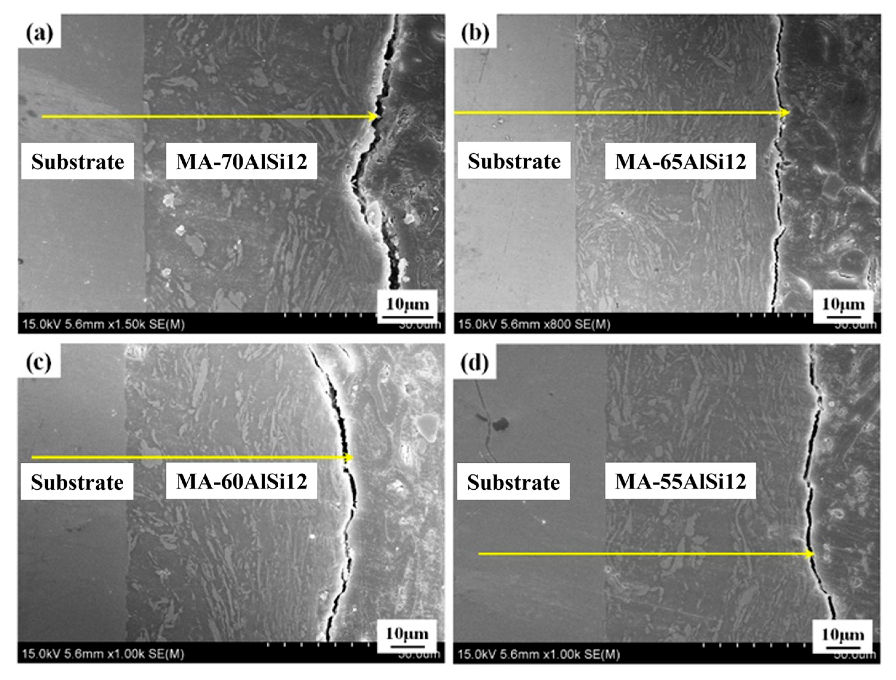
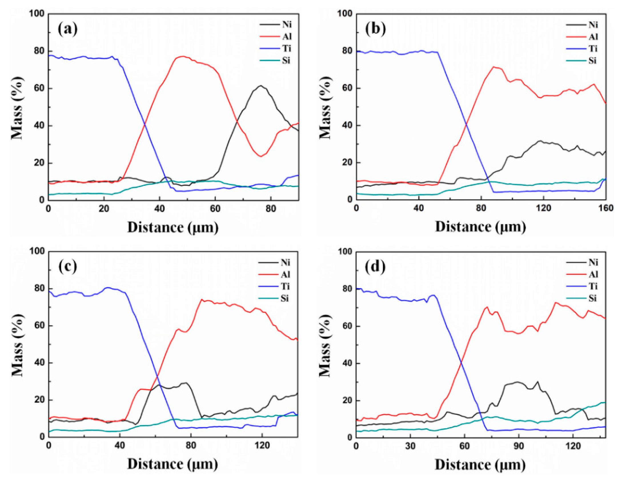
Figure 3 presents the cross-sectional microstructural features of MA coatings fabricated with varying Ni-AlSi12 weight ratios. Coating thickness shows a gradual increase with decreasing AlSi12 content. The coating reaches its maximum thickness (~125 μm) when the original powder contains 60 wt% AlSi12. This is because the reduction in AlSi12 alleviates the work hardening phenomenon during ball milling. When AlSi12 is further reduced, the coating thickness decreases. This is caused by the reduction in AlSi12 as an adhesive. Due to the proper mass ratio of Ni-AlSi12 powder, MA-60AlSi12 has uniform and fine microstructure, and Ni particles are evenly distributed within the matrix phase of AlSi12 alloy. Figure 4 presents the EDS line scanning profiles of MA coatings fabricated with varying powder weight ratios. All MA coatings are mechanically adhered to the substrate without metallurgical bonding. Fluctuations in elemental composition demonstrate the composite nature of the coating. However, the MA-60AlSi12 coating shows more uniform elemental distribution, which also reveals that the MA-60AlSi12 coating sample has a uniform and fine microstructure.
During the ball milling process, the ductile powder AlSi12 undergoes micro-forging, flattening, and fracture, while the brittle Ni powder is broken [32]. The first stage is the crushing process. The repeated collisions between grinding balls and powders flattens the plastic AlSi12 powders and deposits them on the surface of the substrate, forming a seamless interface, while the brittle Ni powders are crushed. In the second stage, ductile AlSi12 powders undergo plastic deformation and are cold-welded as adhesives due to continuous ball collision; the hard and brittle Ni particles are welded with AlSi12 powders on the surface of Ti-6Al-4V substrate to form an inner layer coating with a composite structure. And during this period, the Ni particles are large and unevenly distributed. In the third stage, as the ball milling process continues, the inner coating is compacted, and the defects in the inner coating are reduced significantly. The Ni particles are broken and refined, and eventually dispersed in AlSi12 to form the outer coating. The formation of the coating has two processes of particle peeling and deposition. In the early stage, the deposition of powders occurs on the surface of the substrates. By extending milling time, the peeling and deposition of particles would reach a dynamic equilibrium, resulting in a constant thickness of the coating.
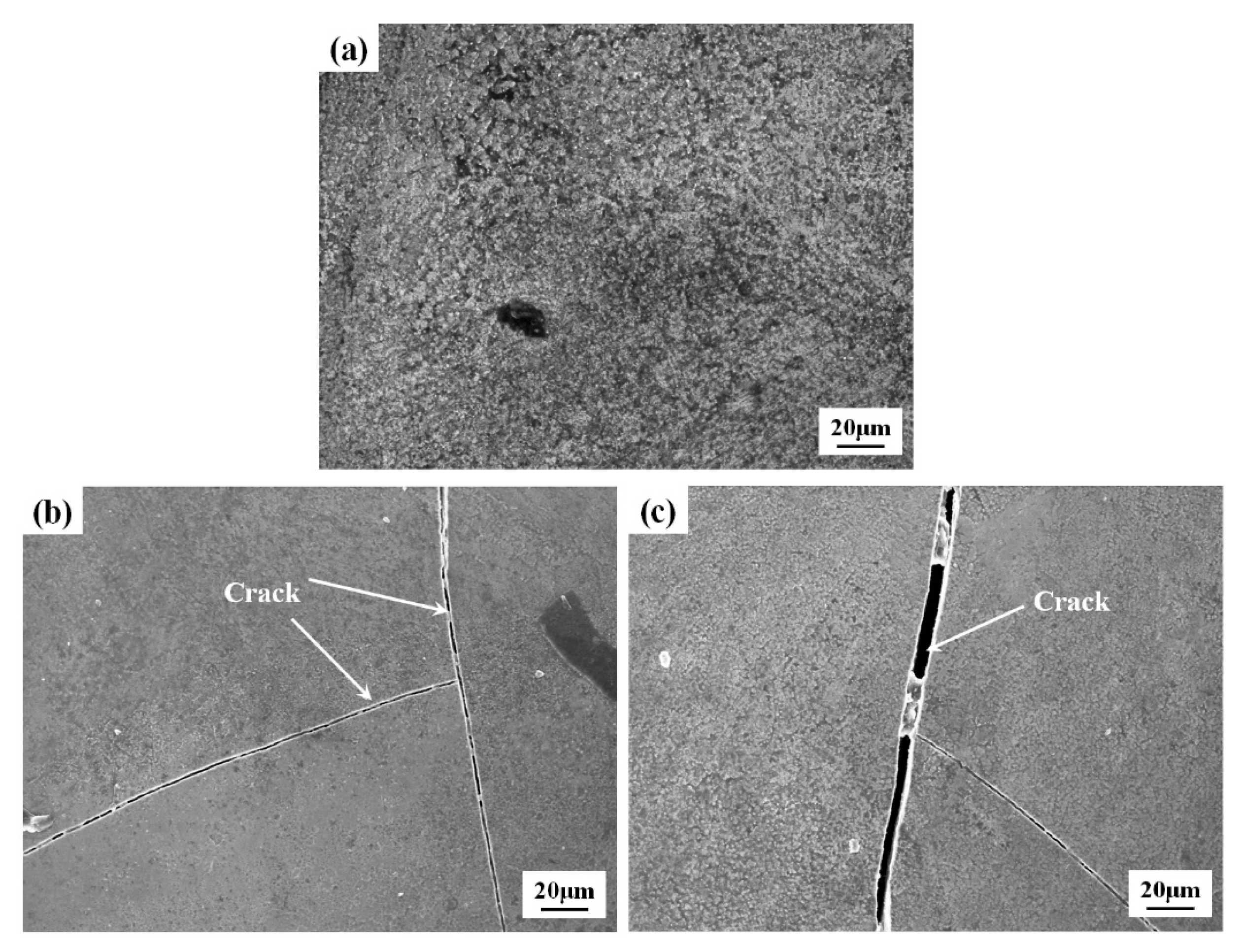
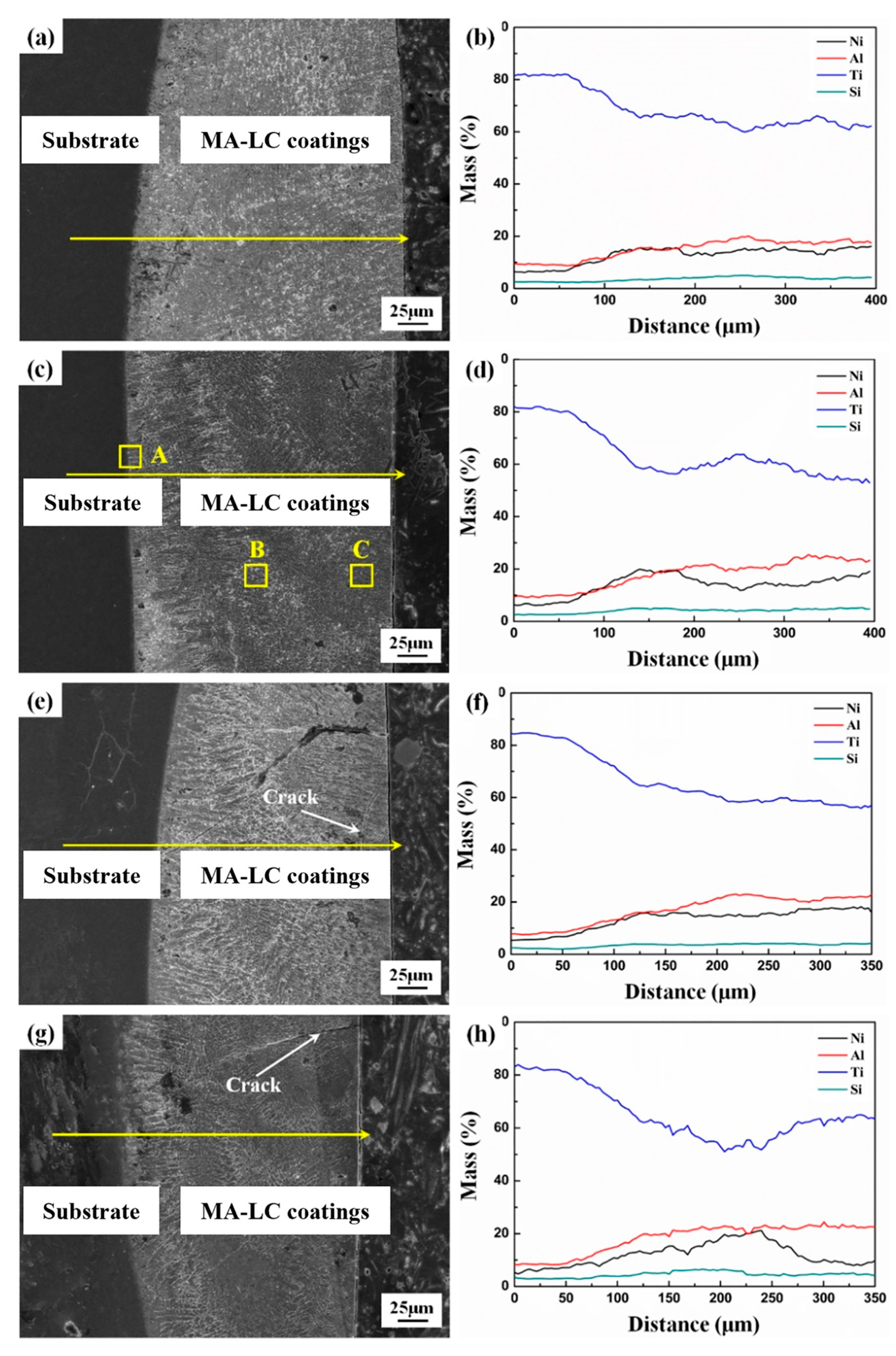
The surface topography of MA-LC coatings processed with varying parameters is presented in Figure 5. The coating demonstrates a defect-free, dense surface morphology at 16.7 J/mm2 laser-specific energy. As the laser-specific energy increases, cracks progressively emerge on the coating surface (Figure 5b,c). The reason lies in the fact that high laser-specific energy means high heat input, which is prone to lead to crack generation and propagation. Figure 6 presents cross-sectional microstructures and associated EDS line scans of MA-LC coatings fabricated at various laser energy densities. The laser-specific energy corresponds to the heat input. At low laser energy density (13.3 J/mm2, Figure 6a), reduced heat input results in shorter molten pool duration and lower processing temperatures [35]. Therefore, the residual gas cannot be discharged in time, leading to the formation of pores at the coating–substrate interface. Under high laser-specific energy conditions, as demonstrated in Figure 6e,g, the cooling rate is excessively high due to the high molten pool temperature, which induces the generation and propagation of cracks. At an appropriate laser-specific energy of 16.7 J/mm2, defects are hardly detectable in the coating’s cross-section, and the coating has a refined microstructure. EDS line scan results of all coated samples are presented in Figure 6b,d,f, and h, respectively. The formation of metallurgical bonds at the coating–substrate interface markedly enhances bonding performance. The coating has a homogeneous chemical composition.
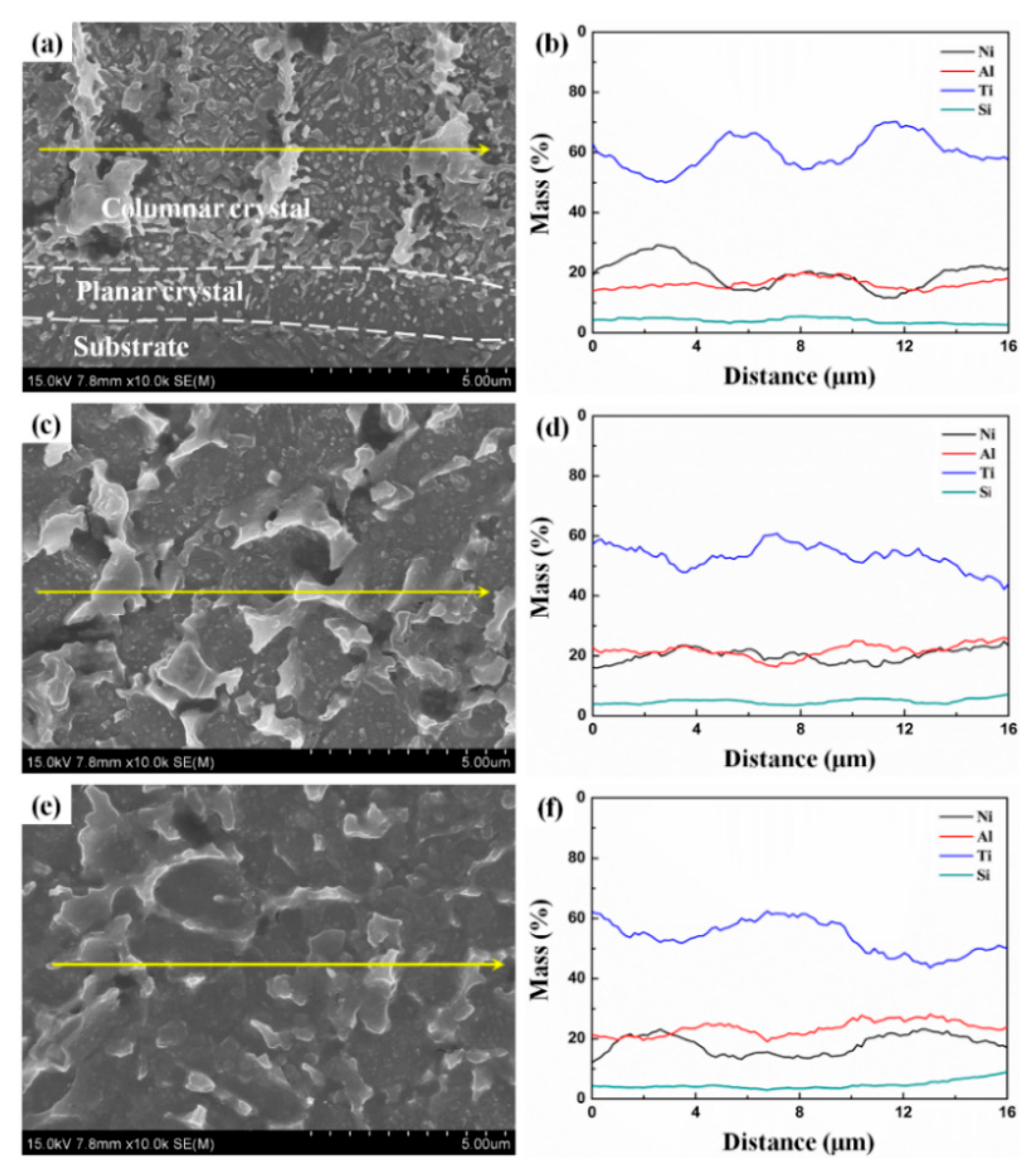
The typical zones A–C from the MA-LC coating (S2) in Figure 6c are further characterized in Figure 7a,c,e. Figure 7b,d,f show the respective EDS line scan results. Figure 7a reveals that the MA-LC coating’s bottom region comprises substrate material, columnar crystals, and planar crystals. As illustrated in Figure 7b, the element fluctuations indicate that there is a great difference in chemical composition between intergranular and intragranular columnar crystals. The central zone of the MA-LC coating (Figure 7c) predominantly displays dendritic crystals. The EDS line scan result (in Figure 7d) suggests that there are also obvious discrepancies between dendrite crystals and inter-dendrites. A high-magnification SEM image characterizing the cross-sectional top area of the MA-LC coating’s cross-section is documented in Figure 7e. It is observed that the coating contains a significant population of refined equiaxed grains. In Figure 7f, the element fluctuation in the top region is gentler. Interestingly, the grain types show a directional change from planar, columnar, and dendritic crystals to equiaxed crystals with increasing cladding layer height. And the grain size exhibits a corresponding reduction, which is mainly dominated by temperature differential and growth speed [36]. In the bottom region, at the interface of the substrate and cladding layer, the temperature gradient is abnormally large, and there is almost no component supercooling. At this time, the crystal grows into the molten pool in a planar manner, so the planar crystal is formed. As the crystal continues to grow into the melt, the temperature gradient decreases, forming a small component supercooling zone, and finally forming columnar crystals [37]. In the middle region, because the temperature gradient becomes gentle, the composition is supercooled to a great extent, and the crystals grow in a dendritic manner. Finally, dendrites are formed in this region [38,39]. In the top region, the temperature gradient is almost nonexistent, and the melt pool temperature is extremely high, resulting in a high cooling rate during solidification [40]. Thus, fine equiaxed crystals are formed.
The XRD results in Figure 8 include MA coatings with different Ni-AlSi12 compositions and their corresponding MA-LC coatings. The MA coatings primarily consist of Al9Si and Ni phases. With the decrease in AlSi12 addition, the intensity of Al9Si peak decreases, while the intensity of Ni peak increases. No significant alloying occurs due to the low temperature maintained during ball milling. Ti peaks are scarcely detectable in the MA coating’s XRD patterns owing to the development of a thick, continuous coating on the Ti-6Al-4V surface. Laser treatment with suitable parameters leads to alloying in the MA-LC coating, resulting in abundant intermetallic formation (NiTi, TiSi, Al3Ti), as revealed in XRD patterns.
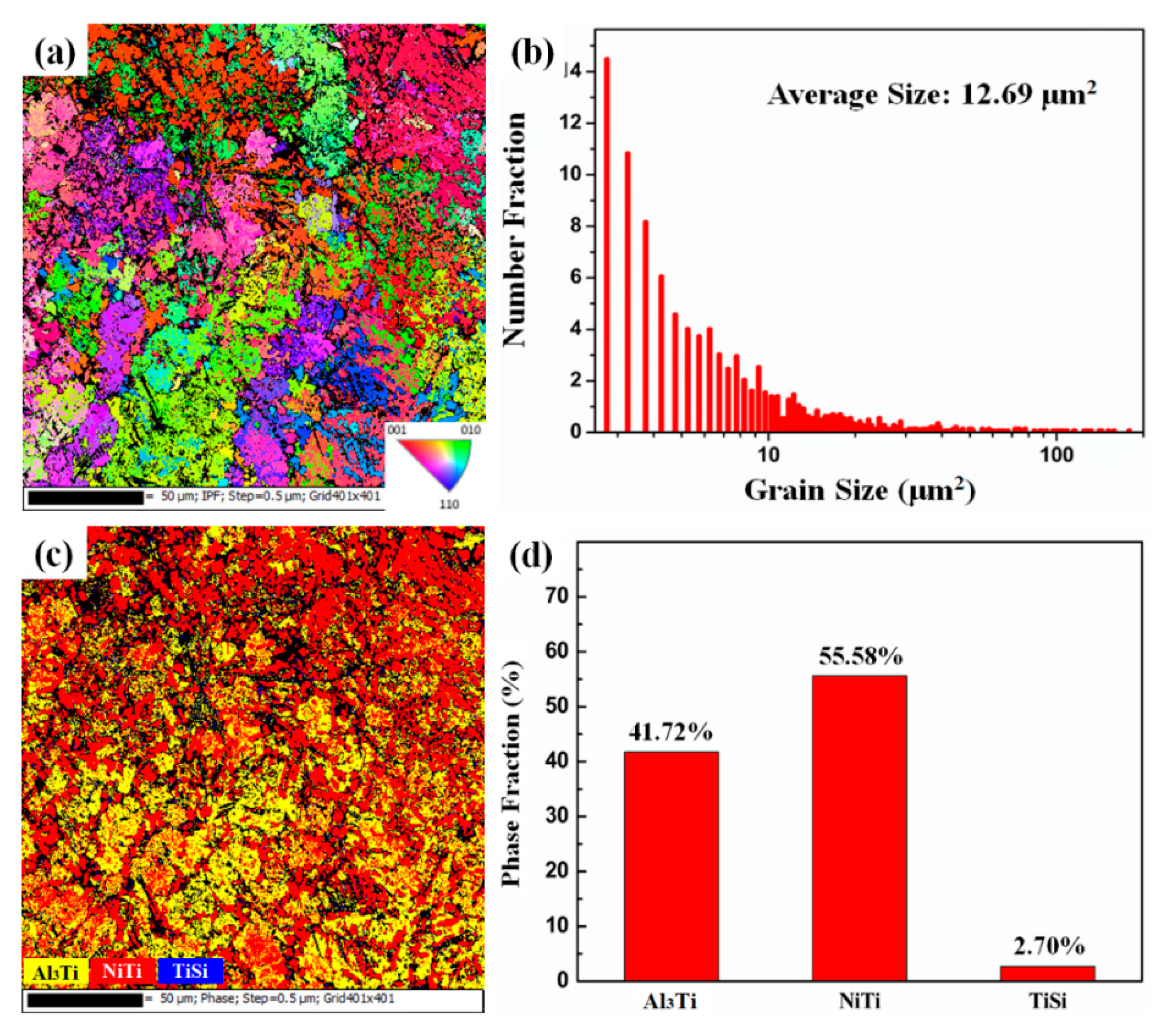
Figure 9a presents the EBSD inverse pole figure (IPF) of the coating after laser treatment. It primarily consists of elongated grains. As illustrated in Figure 9b, the average grain size is 12.69 μm2. Figure 9c,d show the EBSD phase distribution diagram of the coating and the histogram of each comparative example in the coating. It contains three major phases: Al3Ti, NiTi, and minor amounts of TiSi; yellow represents the Al3Ti phase, red represents the NiTi phase, and blue represents the TiSi phase. The proportions of each phase are 41.72%, 55.58%, and 2.70%, respectively.

3.2. Mechanical Properties

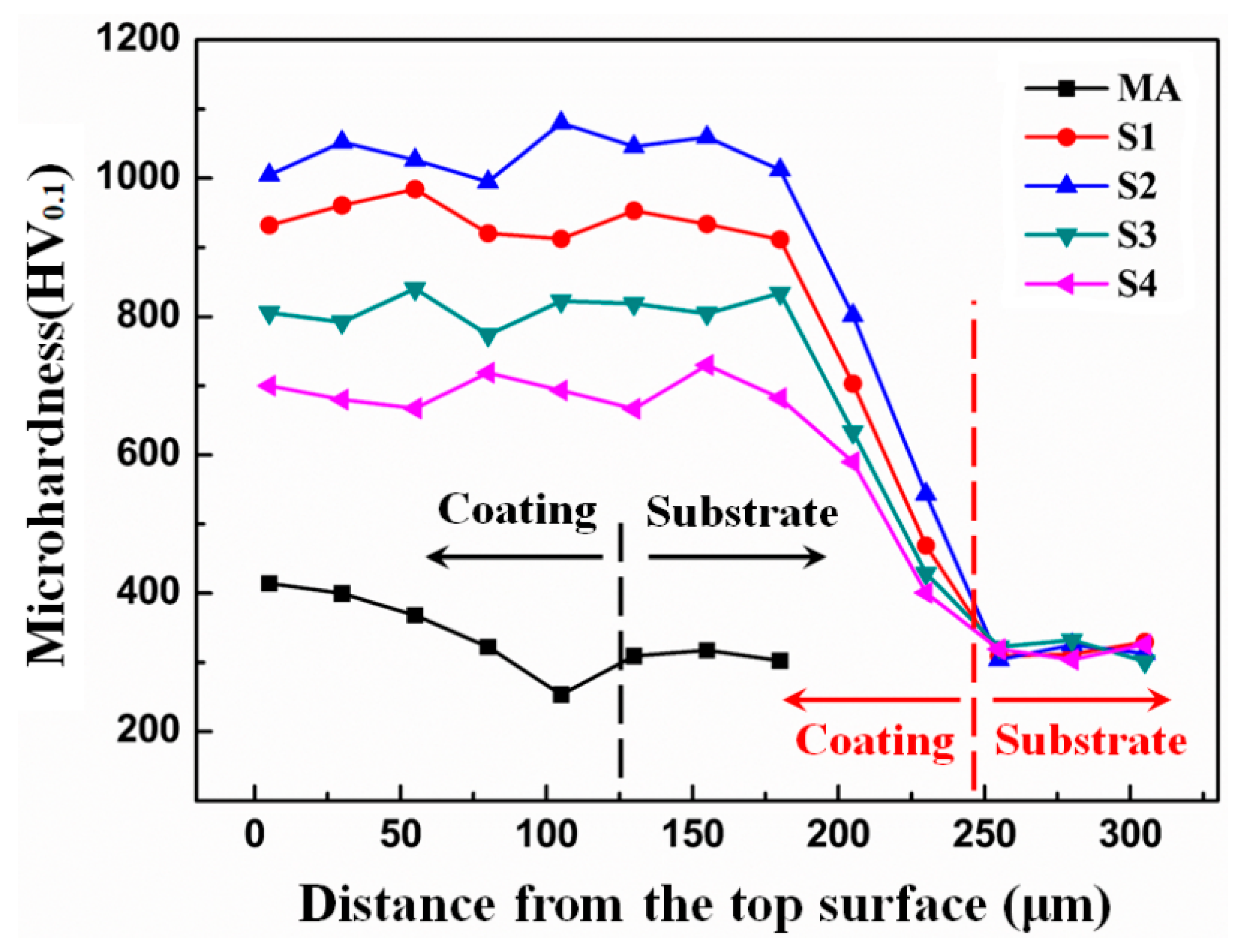
The microhardness distribution from coating surface to substrate is displayed in Figure 10. After laser treatment, significant microhardness enhancement is demonstrated in the coatings compared to the MA coating. When the specific energy of the laser is low, i.e., 13.3 J/mm2, the heat input to the cladding layer is low, the residence time of the melt pool at high temperature is too short, and the gas and slag in the cladding layer cannot be discharged in time, resulting in the formation of pores, which significantly decrease the microhardness of the coating. When Es = 16.7 J/mm2, a large number of Al-Ti and Ni-Ti intermetallic compound particles are formed in the cladding layer. These hard phase particles as the reinforcing phase can efficiently improve the coating’s microhardness. At the same time, owing to the appropriate high temperature residence time of the molten pool, these hard particles do not have sufficient time to coarsen, so the coating can obtain a fine microstructure, which is also conducive to the improvement of its microstructure. Higher laser-specific energy leads to reduced coating microhardness. This is primarily due to the coating’s microstructural coarsening induced by increased laser-specific energy. At the same time, the tendency to produce cracks becomes larger when the intermetallic compound particles are coarse. Therefore, the excessive laser-specific energy density adversely affects the microhardness of the cladding layer.
Figure 11 presents the nano indentation load–displacement curves for both MA and MA-LC coatings. Table 2 summarizes the relevant mechanical property data. The MA-LC coating exhibits a nano-hardness of 9.79 GPa and an elastic modulus of 159.76 GPa, showing significant increases compared to the MA coating. The WEr parameter was calculated using the formula WEr% = [(hm − hp)/hm] × 100%. To a certain extent, it reflects the material’s elastic recovery capability. H3/E2 represents the material’s capacity to resist plastic deformation. For the MA and MA-LC coating systems, the WEr and H3/E2 values were calculated. The MA-LC coating exhibits approximately three times the WEr value (39.66) of the MA coating (12.55), and the MA-LC coating exhibits a H3/E2 100 times greater than its MA counterpart. The H3/E2 exhibits a direct proportionality to coating cohesion strength [41], which can efficiently enhance the coating’s spalling resistance under combined stress and oxidation at elevated temperatures. Conversely, WEr displays an inverse relationship with crack sensitivity [42]; it can effectively suppress crack initiation and propagation during sliding and oxidation. Simultaneously, it could enhance both the coating’s bonding strength and its oxidation resistance at elevated temperatures.
Figure 12 illustrates the optical microscopy images of scratch tracks and corresponding test data for MA and MA-LC coating systems. Figure 12a displays the scratch on the MA coating. Notably, the coating–substrate interface exhibits clear crack formation, thereby confirming adhesive failure in the MA coating during scratch testing. Additionally, as can be observed, porosity is present within the coating. Figure 12b presents the MA coating’s test results, including the 3D surface topography, along with Fz, Fx, and friction coefficient variations versus scratch direction distance. Because of the occurrence of fracture failure in the coating, the scratch depth increases significantly. With Fz preset to 15 N, a sharp Fz increment appears in the coating region. The Fx and the friction coefficient exhibit synchronous fluctuations during scratching, and both exhibit drastic fluctuations on the coating, primarily attributed to the detachment of hard Ni particles from the coating surface. As illustrated in Figure 12c, the MA-LC coating exhibits minimal evidence of cohesive failure or adhesive failure in scratch testing. The MA-LC coating demonstrates outstanding bonding performance. The scratches on the MA-LC coating (Figure 12d) are shallower and narrower than those on the MA coating. The cone depth of the MA coating, as documented in Table 3, is significantly greater compared to the MA-LC coating. The peak Fz attained is 15.75 N, showing a significant increase compared to that of the MA coating. Deformation resistance capacity is quantitatively reflected by Fx values, where higher magnitudes indicate superior performance. This indicates excellent wear performance in the MA-LC coating. Furthermore, the comparative analysis of the projected cone areas (yellow triangles) reveals enhanced scratch bonding performance in the MA-LC coating compared to the MA coating.
In general, coating scratch failure primarily manifests through two distinct modes: one type of failure, where cone-shaped fractures occur along the coating–substrate interface, is referred to as adhesive failure; the other, which occurs through internal coating fractures, is called cohesive failure. Coating bonding performance primarily depends on bonding strength, yet direct characterization of the coating’s bonding strength remains challenging. Thus, optical microscopy images of the scratch are employed to elucidate the failure mode of the coating. Adhesive failure occurs between the MA coating and the substrate under proper load, as evidenced by microcrack formation in scratch testing. Furthermore, the observed holes within scratch tracks confirm the occurrence of cohesive failure in the MA coating. After the scratch test, no defects are observed either within the MA-LC coating or its interfacial region with the substrate. Therefore, during the test, the MA-LC coating exhibits no failure. The mismatch in thermophysical performance between the coating and the substrate is the main cause of adhesive failure. The MA coating and Ti-6Al-4V substrate exhibit mechanical interlocking. Their chemical compositions differ significantly, leading to poor adhesion strength and a severe mismatch in thermal expansion coefficients, which makes adhesive failure highly likely. In parallel, the MA-LC coating forms a metallurgical bond with the substrate, which features stronger bonding force and is less susceptible to adhesive failure. And the coating’s cohesive failure is intimately correlated with its deformation resistance. The MA-LC coating exhibits superior deformation resistance, as evidenced by microhardness and nano-indentation measurements. Thus, the MA-LC coating possesses higher cohesive strength than the MA coating, enabling its effective resistance to cohesive failure. All in all, the bonding properties of the coating can be remarkably boosted through laser treatment.

3.3. High-Temperature Oxidation Resistance

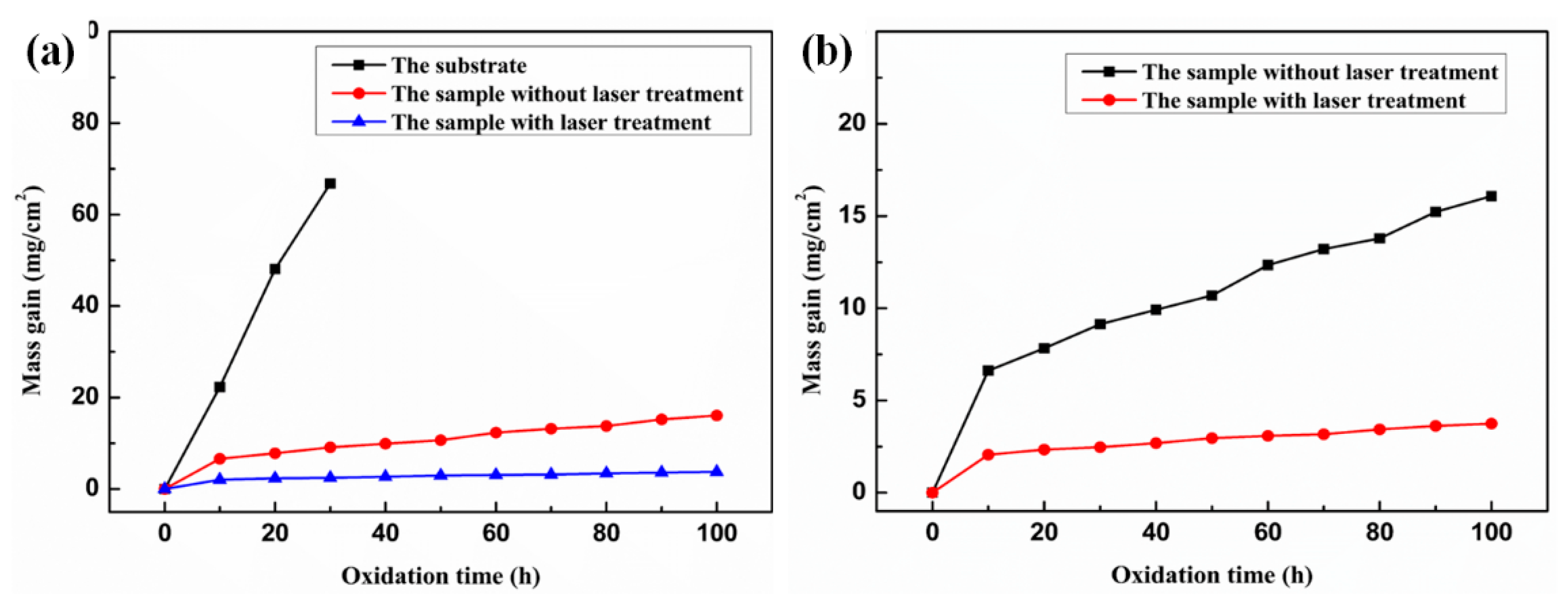
Figure 13a shows oxidation kinetics curves for the substrate, laser-treated coated samples, and untreated coated samples. This demonstrates the correlation between mass gain (MG) per unit area and oxidation duration. A sharp increase in MG value was observed for the Ti-6Al-4V substrate during oxidation. After undergoing 3 × 10 h cyclic oxidation, the oxide layer on the substrate surface peeled off, resulting in failure of the Ti-6Al-4V substrate. Thus, preparing coatings on Ti-6Al-4V substrates is essential for their elevated-temperature oxidation resistance. In comparison to the substrate, both MA-and MA-LC-coated samples show significantly lower mass gain (MG) values. Oxidation kinetics details of coatings produced under various processing conditions are illustrated in Figure 13b. The oxidation kinetics curves of both MA and MA-LC coatings represent a similar tendency. In the initial stage, the coating surface comes into direct contact with air and reacts with oxygen, leading to significant weight gain due to oxidation. Thereafter, the change in MG value of the coating tends to stabilize. At this stage, a compact and dense oxide film develops on the coating surface during prior oxidation, significantly inhibiting further oxidation progression. Therefore, oxygen atoms can only enter the coating through the diffusion channel, so the MG value at this stage is determined by diffusion. In the MA coating, the relatively loose structure provides more channels for oxygen atom diffusion and accelerates the oxidation of the coating at the later stage of oxidation [32]. Therefore, the MA coating demonstrates higher MG values compared to the MA-LC coating, which shows superior elevated-temperature oxidation resistance.
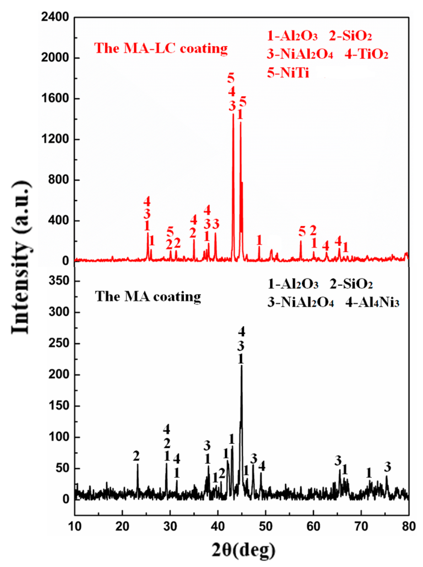
Figure 14 exhibits the X-ray diffraction patterns of MA and MA-LC coatings following 100 h oxidation at 850 °C in air. The results indicate that the MA coating’s oxidation products are primarily composed of Al2O3, SiO2, NiAl2O4, and Al4Ni3 phases. The MA coating undergoes severe oxidation, and during this process, Al4Ni3 is formed by alloying. The XRD pattern revealed that the 100 h oxidized MA-LC coating mainly contains the phases of Al2O3, SiO2, NiAl2O4, TiO2, and a large amount of NiTi. The NiTi matrix phase could be easily detected, suggesting that the oxide film is very thin and easily penetrated by X-rays, which reveals the expected oxidation resistance of the MA-LC coating. During the oxidation process, the formation of oxidation products is extremely complex. It is mainly determined by thermodynamics. In order to predict whether or not the oxidation reaction will happen, the second law of thermodynamics was given, with the corresponding equation as follows:
ΔG = ΔH − TΔS
In this expression, ΔG represents the standard Gibbs free energy variation, ΔH indicates the standard enthalpy variation, T stands for temperature, and ΔS corresponds to the standard entropy variation. In accordance with the second law of thermodynamics, a reaction proceeds spontaneously if its ΔG is less than zero. Hence, the main reactions and associated standard Gibbs free energy of the oxidation process at 850 °C (1123 K) are depicted as follows [43]:
4/3Al(s) + O2(g) = 2/3Al2O3(s) ΔG = −863.67 KJ/mol
Ti(s) + O2(g) = TiO2(s) ΔG = −714.86 KJ/mol
Si(s) + O2(g) = SiO2(s) ΔG = −664.50 KJ/mol
2Ni(s) + O2(g) = 2NiO(s) ΔG = −636.44 KJ/mol
Ni(s) + Ti(s) = NiTi(s) ΔG = −163.58 KJ/mol
Notably, all chemical reactions (reactions (2)–(6)) exhibit negative standard Gibbs free energy values. From a thermodynamic perspective, this suggests that these chemical reactions will happen. Furthermore, among the oxidation products, Al2O3 exhibits the most negative standard Gibbs free energy of formation (ΔGAl2O3). Thus, Al undergoes preferential oxidation under the same reaction. Interestingly, ΔG NiO = −318.44 KJ/mol is also less than zero. However, NiO is barely detectable in the XRD patterns, and NiAl2O4 is the substitute. The reason for this is that the NiO reacts with Al2O3 to produce NiAl2O4 at 850 °C (1123 K); the reaction and corresponding standard Gibbs free energy were illustrated as follows [43,44]:
NiO(s) + Al2O3(s) = NiAl2O4(s) ΔG = −516.95 KJ/mol
Based on reaction (7), the value of ΔGNiAl2O4(s) is negative, which shows that NiAl2O4 oxidation products can grow spontaneously in thermodynamics.
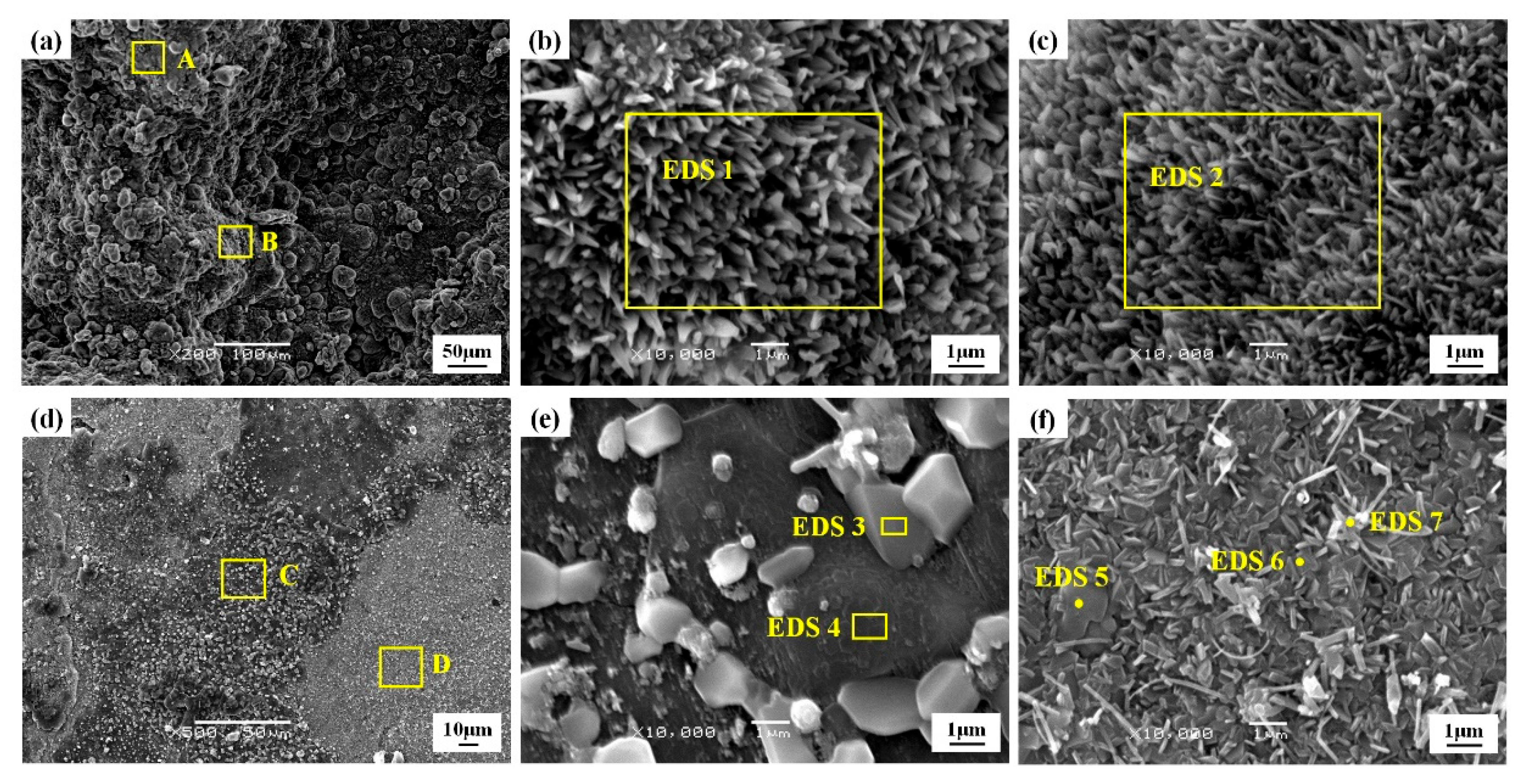
Figure 15 presents the oxidized surface features exhibited by MA and MA-LC coatings after exposure at 850 °C for 100 h. Figure 15a reveals that the MA coating’s surface morphology has a rugged and undulating morphological structure. Meanwhile, the MA-LC coating after oxidation shows a comparatively flat and dense morphological structure (in Figure 15d). Figure 15b,c exhibit the morphological characteristics labeled as areas A and B in Figure 15a, which displays a relatively loose cluster structure. Also, Figure 15e,f present the typical oxidized regions of the MA-LC coating following 100 h oxidation, marked as zones C and D, respectively. And EDS analysis identifies the chemical composition of typical phases on the oxidized coating surface. Table 4 presents the corresponding EDS results. It is clear that the surface of the MA coating suffers severe oxidation owing to the high oxygen content, which mainly consisted of Al2O3 and NiAl2O4. The oxidized MA-LC coating surface mainly includes two characteristic regions: one is an oxidized region (region C in Figure 15d), and the other is an alloyed region (region D in Figure 15d). Region C contains two types of phases, as shown in Figure 15e. One is the white particles (area 3 in Figure 15e), the other is the dark matrix phase (area 4 in Figure 15e). The chemical composition of the white particles is 43.91 at% O, 41.04 at% Al, 7.32 at% Si, 5.29 at% Ni, and 2.44 at% Ti. While the chemical composition of dark matrix phase is 53.96 at% O, 44.00 at% Al, 0.16 at% Si, 1.48 at% Ni, and 0.40 at% Ti. As for the alloyed region (in Figure 15f), it contains a dark mass phase (point 5 in Figure 15f), a dark strip phase (point 6 in Figure 15f), and a gray phase (point 7 in Figure 15f). Relatively, the oxygen content of these three phases is at a low level. This amounts to 31.11 at% O, 36.08 at% Al, 7.61 at% Si, 3.55 at% Ni, and 21.65 at% Ti in point 5; 23.86 at% O, 49.25 at% Al, 6.38 at% Si, 6.99 at% Ni, and 13.53 at% Ti in point 6; and 14.34 at% O, 56.58 at% Al, 4.40 at% Si, 18.40 at% Ni, and 6.28 at% Ti in point 7. Comparing the chemical compositions of these three phases, the existence of Ni and Al is beneficial to inhibit the rise in oxygen content. Thus, the Ni-AlSi12 coating’s original composition significantly improves the Ti-6Al-4V substrate’s elevated-temperature oxidation resistance.
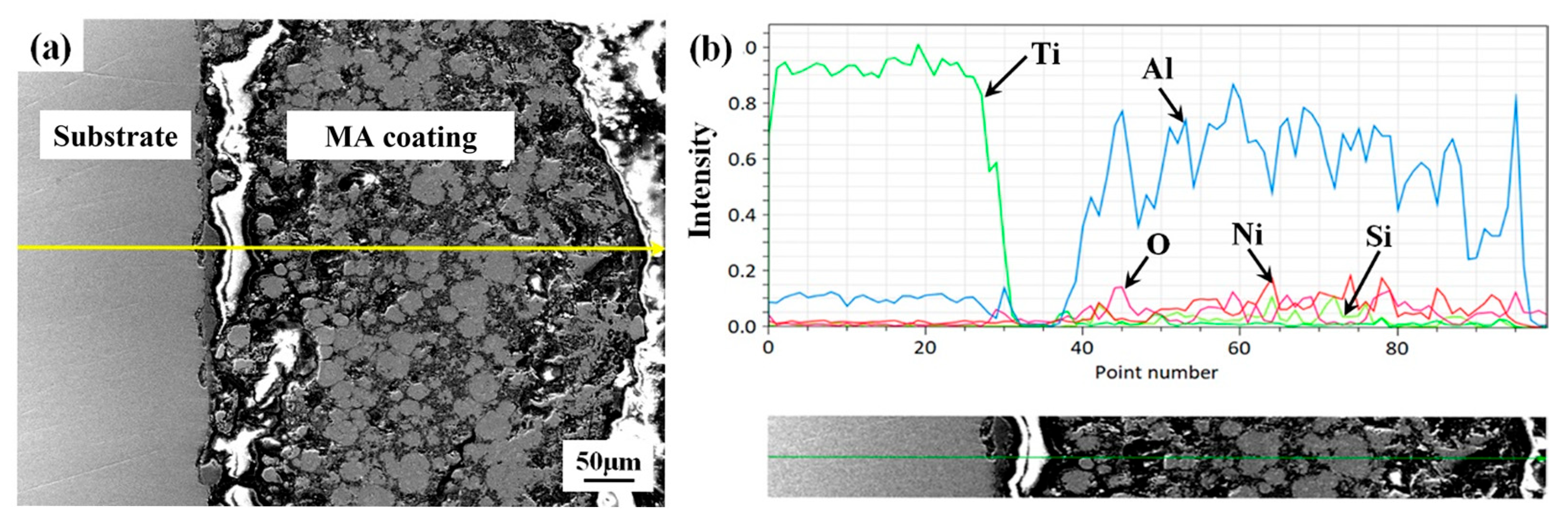
Figure 16 shows the microstructural details of the MA coating following 100 h of oxidation. The cross-section of the oxidized coating in Figure 16a exhibits visible cracks. Following severe oxidation, the coating fails. As demonstrated by the EDS line scanning profile in Figure 16b, oxygen content maintains consistently high levels from the coating exterior to the interior substrate.
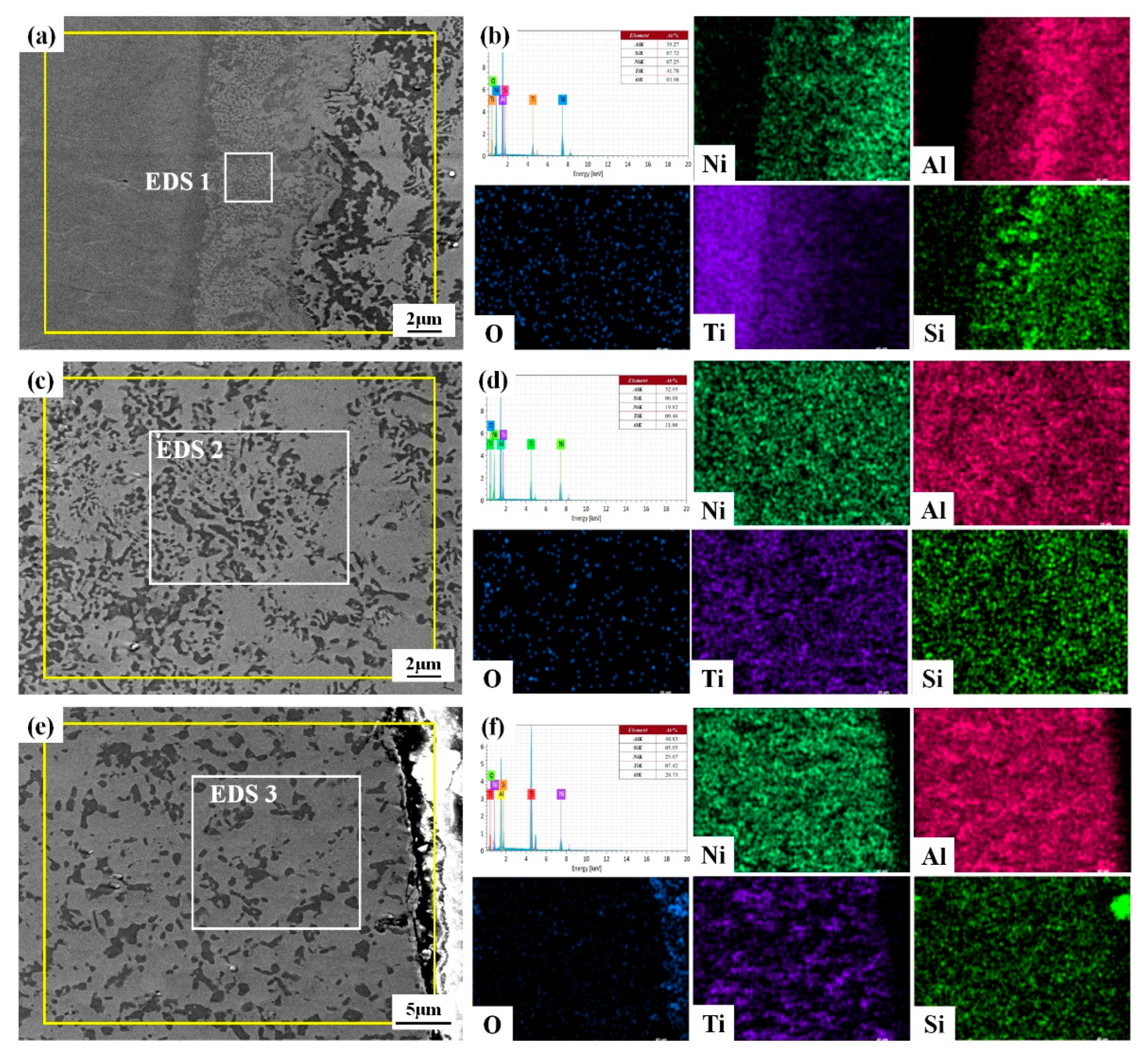
Figure 17 exhibits the microstructural characteristics of the MA-LC coating cross-section following 100 h oxidation. As depicted in Figure 17a, it is hard to observe defects in oxidized coating. As indicated by the EDS line scanning analysis in Figure 17b, the oxygen content in the coating remains low after oxidation, with a sharp increase observed in the top surface layer. The high-magnification SEM image in Figure 18a reveals the bottom region’s layered structure comprising substrate, transition layer, and coating. The relevant EDS results are presented in Figure 18b. The transition layer primarily consists of Al-Ti intermetallic compounds in its chemical composition. A substantial quantity of Si migrates at the interface of the coating and the transition layer, forming a Si-rich interlayer. The microstructure details of the middle region and the top zone are, respectively, exhibited in Figure 18c,e, along with the corresponding EDS data, shown in Figure 17a. In the middle region, a homogeneous microstructure is obtained, which is mainly composed of a dark-gray mass serving as a reinforced phase and a light-gray mass serving as matrix phase. Compared with the XRD patterns in Figure 14, the dark-gray mass is composed of TiO2 and SiO2. The light-gray mass is composed of NiTi, Al2O3 and NiAl2O4. As for the top region, the dark-gray mass is gradually dissolved after being oxidized. Based on the EDS results (1–3), the oxygen concentration exhibits a gradual decrease from the surface region toward the inner substrate. Thus, excellent oxidation resistance at elevated temperatures is observed in the MA-LC coating.
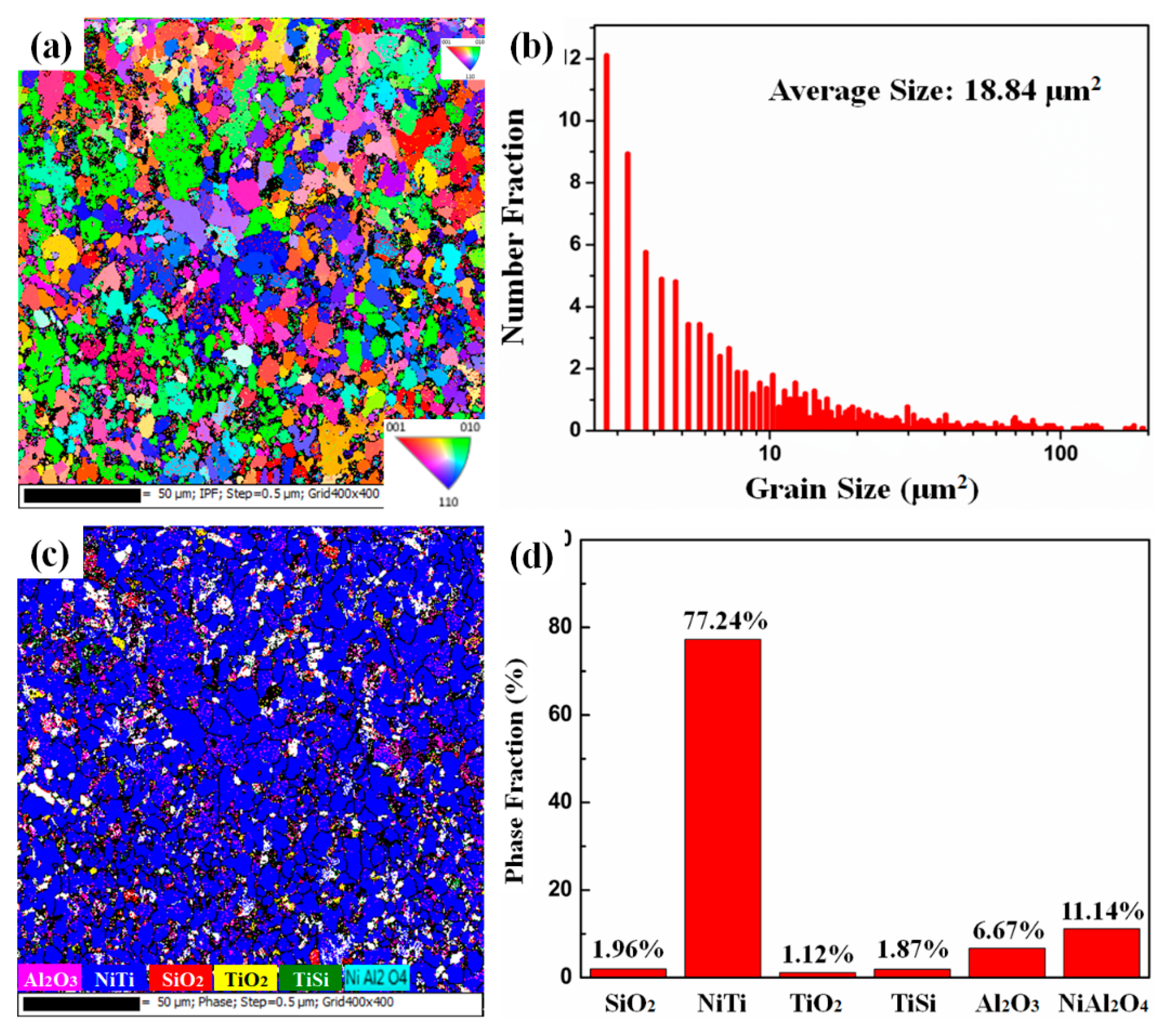
The EBSD reverse polarity diagram of the coating after 100 h of oxidation is displayed in Figure 19a, which is predominantly composed of equiaxed crystals. Through the process of peroxidation, the grains are first oxidized and decomposed, and then grow. Eventually, the grains become coarser, reaching 18.84 μm2 (as depicted in Figure 19b). The reduction in the grain boundary reduces the oxygen diffusion channel, thus reducing the oxidation rate [32]. Figure 19c,d show the EBSD phase distribution of the oxidized coating and the histogram of each comparative example in the coating. The coating is primarily composed of SiO2, NiTi, TiO2, TiSi, Al2O3, and NiAl2O4. Compared with the coating before oxidation, the proportion of the NiTi phase increases, because the oxidation process proceeds simultaneously with alloying, which facilitates the generation of the NiTi intermetallic phase. Excellent plasticity, toughness, and high-temperature oxidation resistance are exhibited by the NiTi phase. The coating’s high-temperature oxidation resistance is enhanced, while crack formation and propagation during repeated heating and cooling are effectively suppressed. However, Al2O3 and NiAl2O4 have a dense structure, which restricts oxygen from permeating further through the coating [45].
As is well-known, in the high-temperature oxidation process, the coating’s microstructure experiences recovery, recrystallization, and grain growth. Figure 20 presents the respective kernel average misorientation (KAM) maps of the coatings before and after oxidation. The literature [46] has shown that the stress distribution of the material is positively correlated with the KAM maps. After oxidizing for 100 h, the stress distribution inside the grain is clearly improved, and the stress is reduced significantly. The stress state at the grain boundary has hardly changed, and there are a lot of stress concentrations at the grain boundary. Owing to recovery recrystallization, the inter-grain stress decreases significantly. However, the decreasing trend of the stress at the grain boundary is rather slow. There are two main reasons for this: First, the grain boundary itself is a defect, and there are other defects at the grain boundary. Second, during high-temperature oxidation, other heterogeneous atoms migrate to the grain boundary, which intensifies the stress concentration. After recrystallization, a noticeable decline in coating defects is accompanied by enhanced material density. The channel of oxygen atoms invading the coating is reduced, which is favorable to enhancing the coating’s oxidation resistance.

4. Conclusions

The surface-modified coatings were prepared via using mechanical alloying with or without subsequent laser cladding on a Ti-6Al-4V substrate. This study investigated how subsequent laser cladding affects the mechanical properties, microstructure, phase composition, and oxidation performance of the mechanically alloyed Ni-AlSi12 composite coating. This study yielded the following key conclusions:
(1)
The coating–substrate interface achieves metallurgical bonding after laser cladding treatment. Also, the MA-LC coating is highly dense and crack-free. It mainly contains Al3Ti and NiTi phases. The average grain size is significantly refined, only 12.69 μm2. The coating exhibits a refined and homogeneous microstructure.
(2)
Owing to the subsequent laser cladding process, the MA-LC coating displays superior mechanical performance in comparison with the MA coating. In comparison to its MA counterpart, the MA-LC coating shows a marked enhancement in microhardness. The nano-hardness of MA-LC coating is 9.79 GPa, exhibiting that it is 6.84 times the nano-hardness of the MA sample. Due to metallurgical bonding, the MA-LC coating exhibits excellent scratch bonding properties.
(3)
During the oxidation process, the MA-LC coating shows desirable oxidation behavior. In the initial oxidation stage, the post-laser-cladding coating shows an elevated oxidation rate, which later declines as a dense Al2O3 oxide layer develops. Post-oxidation analysis reveals a grain coarsening phenomenon in the coating, with the average size increasing from 12.69 μm2 to 18.84 μm2. This reduces the grain boundaries that serve as oxygen diffusion channels. Consequently, the coating demonstrates improved resistance to oxidation. Simultaneously, the corresponding kernel average misorientation (KAM) map of the coating reveals a significant release of internal stress in the coating following 100 h oxidation, which can improve the spallation resistance of the coating.

Author Contributions

Conceptualization, H.X. and H.S.; Methodology, L.X., H.S., H.H. and R.F.; Validation, J.J. and H.H.; Investigation, J.J. and R.F.; Writing—original draft, L.X.; Writing—review and editing, H.X.; Funding acquisition, H.X. All authors have read and agreed to the published version of the manuscript.

Funding

This research was financially supported by the Science and Technology Tackling Project of Henan Province (No. 252102230067 and No. 252102310441) and the Key Scientific Research Project of Higher Education Institutions in Henan Province (No. 25A430040).

Institutional Review Board Statement

Not applicable.

Informed Consent Statement

Not applicable.

Data Availability Statement

Data are contained within the article.

Conflicts of Interest

The authors declare no conflicts of interest.

References

  1. Ezugwu, E.O.; Wang, Z.M. Titanium alloys and their machinability—A review. J. Mater. Process. Technol. 1997, 68, 262–274. [Google Scholar] [CrossRef]
  2. Okulov, I.V.; Volegov, A.S.; Attar, H.; Bönisch, M.; Ehtemam-Haghighi, S.; Calin, M.; Eckert, J. Composition optimization of low modulus and high-strength TiNbbased alloys for biomedical applications. J. Mech. Behav. Biomed. 2017, 65, 866–871. [Google Scholar] [CrossRef]
  3. Okulov, I.V.; Wendrock, H.; Volegov, A.S.; Attar, H.; Kühn, U.; Skrotzki, W.; Eckert, J. High strength beta titanium alloys: New design approach. Mater. Sci. Eng. A 2015, 628, 297–302. [Google Scholar] [CrossRef]
  4. Tian, Y.; Chen, C.; Chen, L.; Huo, Q. Wear and oxidation resistance of composite coatings fabricated on Ti-6Al-4V by laser alloying with nitrogen and silicon. J. Phys. D 2005, 38, 4217–4221. [Google Scholar] [CrossRef]
  5. Zhou, W.; Zhao, Y.; Li, W.; Qin, Q.; Tian, B.; Hu, S. Al-Si coating fused by Al + Si powders formed on Ti–6Al–4V alloy and its oxidation resistance. Mater. Sci. Eng. A 2006, 430, 142–150. [Google Scholar] [CrossRef]
  6. Zhou, Q.; Ren, Y.; Du, Y.; Han, W.; Hua, D.; Zhai, H.; Huang, P.; Wang, F.; Wang, H. Identifying the significance of Sn addition on the tribological performance of Ti-based bulk metallic glass composites. J. Alloys Compd. 2019, 780, 671–679. [Google Scholar] [CrossRef]
  7. Xiao, C.; Zhang, H.; Davoodi, D.; Miri, R.; Tayebi, M. Microstructure evolutions of Ti-Al-Nb alloys with different Ta addition, produced by mechanical alloying and spark plasma sintering. Mater. Lett. 2022, 323, 132568. [Google Scholar] [CrossRef]
  8. Duan, Q.; Luan, Q.; Liu, J.; Peng, L. Microstructure and mechanical properties of directionally solidified high-Nb containing Ti–Al alloys. Mater. Des. 2010, 31, 3499–3503. [Google Scholar] [CrossRef]
  9. Maestro, C.A.R.; Moreto, J.A.; Chiaramonte, T.; Gelamo, R.V.; Oliveira, C.F.; Santos, M.M.; Silva, M.V.; Bueno, A.H.S.; Balestra, R.M.; Malafaia, A.M.S. Corrosion behavior and biological responses of a double coating formed on the Ti-6Al-4V alloy surface by using thermal oxidation and biomimetic deposition of bismuth-doped CaP. Surf. Coat. Technol. 2021, 425, 127717. [Google Scholar] [CrossRef]
  10. Xu, J.; Ding, G.; Li, J.; Yang, S.; Fang, B.; Sun, H.; Zhou, Y. Zinc-ion implanted and deposited titanium surfaces reduce adhesion of Streptococccus mutans. Appl. Surf. Sci. 2010, 256, 7540–7544. [Google Scholar] [CrossRef]
  11. Lei, J.; Shi, C.; Zhou, S. Enhanced corrosion and wear resistance properties of carbon fiber reinforced Ni-based composite coating by laser cladding. Surf. Coat. Technol. 2018, 334, 274–285. [Google Scholar] [CrossRef]
  12. Blanco, D.; Viesca, J.L.; Mallada, M.T. Wettability and corrosion of [NTf2] anionbased ionic liquids on steel and PVD (TiN, CrN, ZrN) coatings. Surf. Coat. Technol. 2016, 302, 13–21. [Google Scholar] [CrossRef]
  13. Suryanarayana, C. Mechanical alloying and milling. Prog. Mater. Sci. 2001, 46, 1–184. [Google Scholar] [CrossRef]
  14. Groza, J.R. Nanocrystalline powder consolidation method. In Nanostructured Materials-Processing, Properties and Potential Applications, 2nd ed.; Koch, C.C., Ed.; William Andrews Publication: New York, NY, USA, 2006. [Google Scholar]
  15. Chen, C.; Feng, X.; Shen, Y. Synthesis of Al–B4C composite coating on Ti–6Al–4V alloy substrate by mechanical alloying method. Surf. Coat. Technol. 2017, 321, 8–18. [Google Scholar] [CrossRef]
  16. Lu, C.; Tian, Y.; Shen, Y.; Feng, X.; Jiang, J. Thermal shock resistance and thermal conductivity of diamond-Cu composite coatings on Cu substrate via mechanical milling method. Surf. Coat. Technol. 2018, 352, 529–540. [Google Scholar] [CrossRef]
  17. Chen, C.; Feng, X.; Shen, Y. Effects of annealing treatment and pre-refinement of raw material on microstructures and properties of mechanically alloyed Cr–Al composite coatings on Ti–6Al–4V alloy. Mater. Character. 2016, 120, 97–108. [Google Scholar] [CrossRef]
  18. Wang, D.; Tian, Z.; Shen, L.; Huang, Y. Research status and development of laser cladding technology. Appl. Laser 2012, 32, 538–544. [Google Scholar]
  19. Liu, J.; Song, M.; Chen, C.; Liu, H. Research progress on laser cladding technology of titanium alloy surface. Heat Treat. Met. 2019, 44, 87–96. [Google Scholar]
  20. Chakraborty, R.; Raza, M.S.; Datta, S.; Saha, P. Synthesis and characterization of nickel free titanium–hydroxyapatite composite coating over nitinol surface through in-situ laser cladding and alloying. Surf. Coat. Technol. 2019, 358, 539–550. [Google Scholar] [CrossRef]
  21. Zhang, Y.L.; Li, J.; Zhang, Y.Y.; Kang, D.N. Evolution in microstructure and high-temperature oxidation behaviors of the laser-cladding coatings with the Si addition contents. J. Alloys Compd. 2020, 827, 154131. [Google Scholar] [CrossRef]
  22. Carrullo, J.C.Z.; Falcon, J.C.P.; Borras, V.A. Influence of process parameters and initial microstructure on the oxidation resistance of Ti48Al2Cr2Nb coating obtained by laser metal deposition. Surf. Coating. Technol. 2019, 358, 114–124. [Google Scholar] [CrossRef]
  23. Liu, H.X.; Zhang, X.W.; Jiang, Y.H.; Zhou, R. Microstructure and high temperature oxidation resistance of in-situ synthesized TiN/Ti3Al intermetallic composite coatings on Ti6Al4V alloy by laser cladding process. J. Alloys Compd. 2016, 670, 268–274. [Google Scholar] [CrossRef]
  24. Diao, Y.H.; Zhang, K.M. Microstructure and corrosion resistance of TC2 Ti alloy by laser cladding with Ti/TiC/TiB2 powders. Appl. Surf. Sci. 2015, 352, 163–168. [Google Scholar] [CrossRef]
  25. Tan, H.; Luo, Z.; Li, Y.; Yan, F.; Duan, R.; Huang, Y. Effect of strengthening particles on the dry sliding wear behavior of Al2O3-M7C3/Fe metal matrix composite coatings produced by laser cladding. Wear 2015, 324, 36–44. [Google Scholar] [CrossRef]
  26. Akbari, M.K.; Baharvandi, H.R.; Shirvanimoghaddam, K. Tensile and fracture behavior of nano/micro TiB2, particle reinforced casting A356 aluminum alloy composites. Mater. Des. 2015, 66, 150–161. [Google Scholar] [CrossRef]
  27. Zhou, S.F.; Dai, X.Q. Laser induction hybrid rapid cladding of WC particles reinforced NiCrBSi composite coating. Appl. Surf. Sci. 2010, 256, 4708–4714. [Google Scholar] [CrossRef]
  28. Yu, T.; Deng, Q.L.; Zheng, J.F.; Dong, G.; Yang, J.G. Microstructure and wear behaviour of laser clad NiCrBSi + Ta composite coating. Surf. Eng. 2013, 28, 357–363. [Google Scholar] [CrossRef]
  29. Wang, X.H.; Zhang, M.; Du, B.S.; Li, S. Microstructure and wear properties of laser clad (TiB2 + TiC)/Fe composite coating. Surf. Rev. Lett. 2012, 19, 1250052. [Google Scholar] [CrossRef]
  30. Ma, Q.S.; Li, Y.J.; Wang, J.; Liu, K. Microstructure evolution and growth control of ceramic particles in wide-band laser clad Ni60/WC composite coatings. Mater. Des. 2016, 92, 897–905. [Google Scholar]
  31. Peng, Y.; Zhang, W.; Li, T.; Zhang, M.; Liu, B.; Liu, Y.; Wang, L.; Hu, S. Effect of WC content on microstructures and mechanical properties of FeCoCrNi high-entropy alloy/WC composite coatings by plasma cladding. Surf. Coat. Technol. 2020, 385, 125326. [Google Scholar] [CrossRef]
  32. Jiang, J.; Feng, X.; Shen, Y.; Lu, C.; Tian, Y. Oxidation behavior of Cr-AlSi12 composite coatings on Ti-6Al-4V alloy substrate fabricated via high-energy mechanical alloying method. Surf. Coat. Technol. 2019, 367, 212–224. [Google Scholar] [CrossRef]
  33. Sun, S.; Liu, J.-G.; Yan, C.-W.; Wang, F.-H. A novel process for electroless nickel plating on anodized magnesium alloy. Appl. Surf. Sci. 2008, 254, 5016–5022. [Google Scholar] [CrossRef]
  34. Wei, Y.K.; Li, Y.J.; Zhang, Y.; Luo, X.T.; Li, C.J. Corrosion resistant nickel coating with strong adhesion on AZ31B magnesium alloy prepared by an in-situ shot-peening-assisted cold spray. Corros. Sci. 2018, 138, 105–115. [Google Scholar] [CrossRef]
  35. Liu, J.; Shi, Y. Microstructure and wear behavior of laser-cladded Ni-based coatings decorated by graphite particles. Surf. Coat. Technol. 2021, 412, 127044. [Google Scholar] [CrossRef]
  36. Morawiec, M.; Rozanski, M.; Grajcar, A.; Stano, S. Effect of dual beam laser welding on microstructure–property relationships of hot-rolled complex phase steel sheets. Arch. Civ. Mech. Eng. 2017, 17, 145–153. [Google Scholar] [CrossRef]
  37. Dinda, G.P.; Dasgupta, A.K.; Mazumder, J. Laser aided direct metal deposition of Inconel 625 superalloy: Microstructural evolution and thermal stability. Mater. Sci. Eng. A 2009, 509, 98–104. [Google Scholar] [CrossRef]
  38. Torres, H.; Slawik, S.; Gachot, C.; Prakash, B.; Ripoll, M.R. Microstructural design of self-lubricating laser claddings for use in high temperature sliding applications. Surf. Coat. Technol. 2018, 337, 24–34. [Google Scholar] [CrossRef]
  39. Zheng, C.; Liu, Z.; Chen, S.; Liu, C. Corrosion behavior of a Ni-Cr-Mo alloy coating fabricated by laser cladding in a simulated sulfuric acid dew point corrosion environment. Coatings 2020, 10, 849. [Google Scholar] [CrossRef]
  40. Ren, L.; Ding, Y.; Cheng, Y.; Nong, J.; Wang, S.; Wang, S.; Zhang, D.; Qin, Q.; Si, J.; Shoji, T.; et al. The microstructure evolving and element transport of Ni-based laser-cladding layer in supercritical water. Corros. Sci. 2022, 198, 110112. [Google Scholar] [CrossRef]
  41. Luo, X.X.; Yao, Z.J.; Zhang, P.Z.; Gu, D.D.; Chen, Y. Laser cladding Fe-Al-Cr coating with enhanced mechanical properties. J. Wuhan Univ. Technol.-Mater. Sci. Ed. 2019, 34, 1197–1204. [Google Scholar] [CrossRef]
  42. Cao, S.; Liang, J.; Wang, L.; Zhou, J. Effects of NiCr intermediate layer on microstructure and tribological property of laser cladding Cr3C2 reinforced Ni60A-Ag composite coating on copper alloy. Opt. Laser Technol. 2021, 142, 106963. [Google Scholar] [CrossRef]
  43. Barin, I. Thermochemical Data of Pure Substance, 3rd ed.; Wiley-VCH: Weinheim, Germany, 1995. [Google Scholar]
  44. Tang, J.J.; Bai, Y.; Zhang, J.C.; Liu, K.; Liu, X.Y.; Zhang, P.; Wang, Y.; Zhang, L.; Liang, G.Y.; Gao, Y.; et al. Microstructural design and oxidation resistance of CoNiCrAlY alloy coatings in thermal barrier coating system. J. Alloys Compd. 2016, 688, 729–741. [Google Scholar] [CrossRef]
  45. Li, W.; Zhang, W.L.; Li, T.; Pen, X.; Sun, J.; Wang, T.G.; Jiang, S.M.; Gong, J.; Sun, C. Improvement of cyclic oxidation resistance of a β-(Ni,Pt)Al coating by the addition of Ni/Ni-Re layer at 1150 °C. Corros. Sci. 2022, 207, 110486. [Google Scholar] [CrossRef]
  46. Calcagnotto, M.; Ponge, D.; Demir, E.; Raabe, D. Orientation gradients and geometrically necessary dislocations in ultrafine grained dual-phase steels studied by 2D and 3D EBSD. Mater. Sci. Eng. A 2010, 527, 2738–2746. [Google Scholar] [CrossRef]
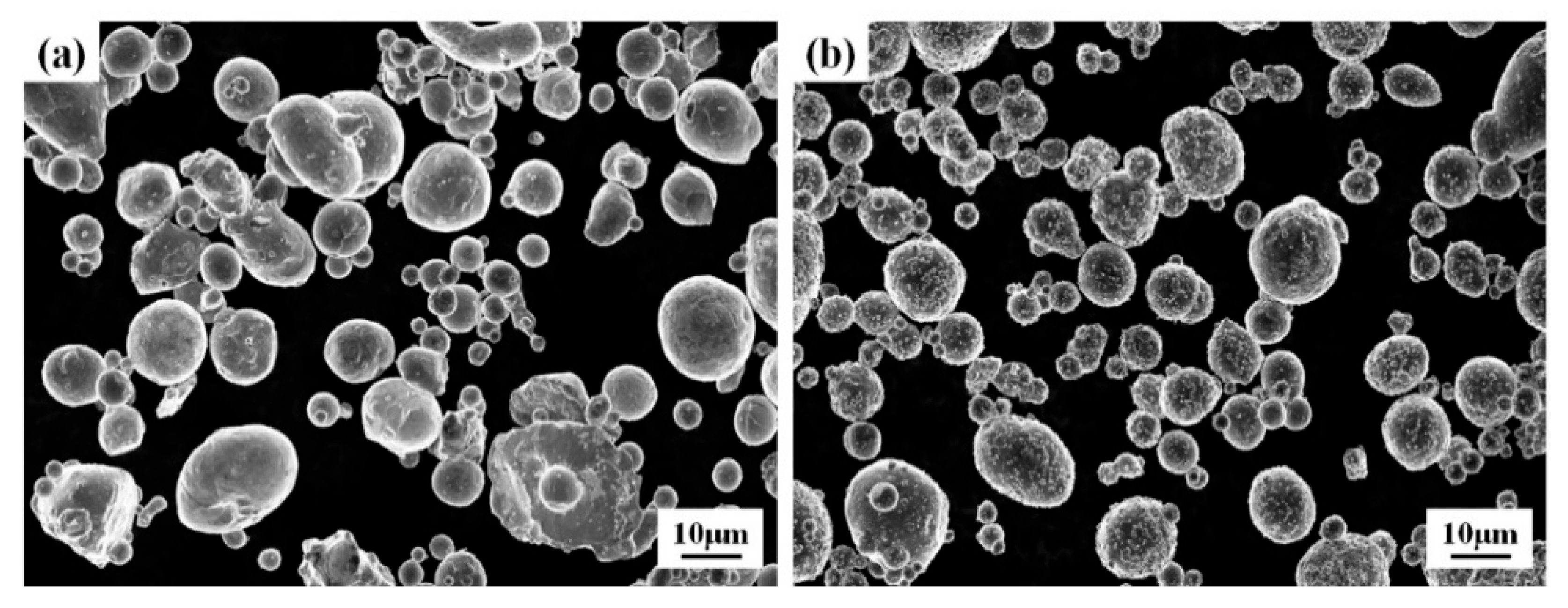
Figure 1. The morphological characteristics of the starting powders: (a) Ni powder; (b) AlSi12 alloy powder.
Coatings 15 01329 g001
Figure 2. MA coating surface morphology at varying Ni-AlSi12 powder weight ratios: (a) 30:70, (b) 35:65, (c) 40:60, (d) 45:55.
Coatings 15 01329 g002
Figure 3. Cross-sectional SEM images of mechanically alloyed (MA) coatings deposited on Ti-6Al-4V substrate with varying Ni-AlSi12 powder weight ratios: (a) 30:70, (b) 35:65, (c) 40:60, (d) 45:55.
Coatings 15 01329 g003
Figure 4. The EDS line scanning profiles acquired along the arrow-marked paths in Figure 3a–d, corresponding to (ad), respectively.
Coatings 15 01329 g004
Figure 5. Surface morphologies of MA-LC coatings processed with distinct parameters are shown in panels (ac): (a) S2, (b) S3, and (c) S4.
Coatings 15 01329 g005
Figure 6. Microstructural cross-section features and matching EDS line scan findings of MA-LC coatings fabricated under varied laser cladding conditions: (a) cross-section microstructure of S1 sample; (b) EDS line scan results of S1 sample; (c) cross-section microstructure of S2 sample; (d) EDS line scan results of S2 sample; (e) cross-section microstructure of S3 sample; (f) EDS line scan results of S3 sample; (g) cross-section microstructure of S4 sample; (h) EDS line scan results of S4 sample.
Coatings 15 01329 g006
Figure 7. Microstructural features in Figure 6c are designated as zones A–C (shown in (a,c,e), while corresponding elemental profiles are presented in (b,d,f) through EDS line scanning.
Coatings 15 01329 g007
Figure 8. The XRD results of the MA coatings fabricated with distinct Ni-AlSi12 weight ratios and the MA-LC coating.
Coatings 15 01329 g008
Figure 9. EBSD analysis of MA-LC coating: (a) inverse pole figure (IPF) map, (b) grain size histograms, (c) EBSD phase maps, (d) phase histograms.
Coatings 15 01329 g009
Figure 10. Distribution of coating microhardness from the coating exterior to the substrate.
Coatings 15 01329 g010
Figure 11. Nano-indentation results for MA and MA-LC coatings.
Coatings 15 01329 g011
Figure 12. Optical microscopy (OM) images display the scratch tracks on the MA coating (a) and MA-LC coating (c), while 3D surface profiles and corresponding scratch test data are presented for the MA (b) and MA-LC (d) coatings.
Coatings 15 01329 g012
Figure 13. Oxidation kinetics comparison: substrate vs. coated samples (with/without laser treatment) (a); coated samples under varied processing conditions (b).
Coatings 15 01329 g013
Figure 14. The XRD patterns of MA and MA-LC coatings following 100 h of oxidation.
Coatings 15 01329 g014
Figure 15. Surface morphology of the MA (a) and MA-LC (d) coatings after 100 h oxidation; (b,c) show the elevated-magnification microstructure of regions A and B in (a), while (e,f) display the elevated-magnification microstructure of areas C and D in (d).
Coatings 15 01329 g015
Figure 16. Cross-sectional characterization of 100 h oxidized MA coating: (a) microstructure, (b) EDS line scanning profile.
Coatings 15 01329 g016
Figure 17. Cross-sectional characterization of 100 h oxidized MA-LC coating: (a) microstructure, (b) EDS line scanning profile.
Coatings 15 01329 g017
Figure 18. The SEM image of the bottom area in the coating (a), the EDS result of zone 1 and corresponding EDS mapping of bottom area (b); the SEM result of the middle area in the coating (c); the EDS result of zone 2 and corresponding EDS mapping of middle area (d); the SEM result of the coating’s surface region (e); the EDS result of zone 3 and corresponding EDS mapping of top area (f).
Coatings 15 01329 g018
Figure 19. EBSD analysis of MA-LC coating after 100 h oxidation: (a) inverse pole figure (IPF) map, (b) grain size histograms, (c) EBSD phase maps, (d) phase histograms.
Coatings 15 01329 g019
Figure 20. The respective kernel average misorientation (KAM) maps of MA-LC coatings: (a) as-received; (b) post-oxidation.
Coatings 15 01329 g020
Table 1. Processing parameters and laser energy density in laser cladding.
CoatingsLaser Power P (W)Scanning Speed v (mm/s)Laser Beam Diameter D (mm)Laser-Specific Energy Es (J/mm2)
S1200101.513.3
S2300121.516.7
S330081.525.0
S4450101.530.0
Table 2. Mechanical properties of the MA and MA-LC coatings.
Mechanical PropertiesMA CoatingMA-LC Coating
Nanohardness H (GPa)1.519.79
Elastic modulus E (GPa)96.51159.76
WEr (%)12.5539.66
H3/E20.000370.03676
Table 3. Test results of the coatings’ average scratch bond strength.
CoatingCone Depth (µm)Projected Cone Perimeter (µm)Projected Cone Area (µm2)Type of Failure
MA7.685457.410,059Adhesive/Cohesive
MA-LC6.285339.34951No failure
Table 4. Elemental composition analysis (EDS) of oxidized coating surfaces (at.%).
ElementArea 1Area 2Area 3Area 4Area 5Area 6Area 7
OK48.1842.3943.9153.9631.1123.8614.34
AlK36.0441.1041.0444.0036.0849.2556.58
SiK3.551.887.320.167.616.384.40
NiK12.2414.635.291.483.556.9918.40
TiK--2.440.4021.6513.536.28
Disclaimer/Publisher’s Note: The statements, opinions and data contained in all publications are solely those of the individual author(s) and contributor(s) and not of MDPI and/or the editor(s). MDPI and/or the editor(s) disclaim responsibility for any injury to people or property resulting from any ideas, methods, instructions or products referred to in the content.