1. Introduction
The diversification of transportation media and the complexity of transportation environments have put forward higher requirements for the strength, corrosion resistance, and high temperature resistance of pipelines. Bimetallic composite pipes were born to meet the above requirements. The base pipe (outer pipe) uses cheaper steel for strength support, while the liner pipe (inner pipe) uses metals or alloys with good corrosion and wear resistance to resist corrosion or wear. Therefore, it combines the advantages of both base pipe and liner pipe materials and has been widely used in the petroleum and natural gas industry [
1,
2].
Bimetallic composite pipes can achieve metallurgical bonding (such as hot rolling [
3], hot extrusion, explosive welding [
4], solid–liquid casting and rolling [
5,
6], and centrifugal casting [
7]) or mechanical bonding (such as spinning [
7], cold rolling, and hydraulic bulging [
8]) between the inner wall of the base pipe and the outer wall of the liner pipe through certain processing methods. With the development of green manufacturing and lightweight technology, the demand for hydraulic-formed bimetallic composite pipes will continue to increase due to their advantages such as uniform contact pressure distribution, and no scratches or mechanical damage on the lining surface [
8]. Therefore, studying the hydraulic forming process of bimetallic composite pipes has important practical significance.
In recent years, scholars both domestic and abroad have conducted extensive research on the hydraulic forming process of bimetallic composite pipes. A.R. Akisanya et al. [
9] established a relationship between bulging pressure, geometric dimensions of the tube, and residual contact pressure using elastic and plastic theories. With the rise and increasing maturity of finite element numerical simulation methods, many scholars both domestically and internationally have employed this approach to study hydraulic bulging processes. Olabi and Alaswad [
7] developed a finite element model for the hydraulic bulging of bimetallic tubes using ANSYS LS-DYNA preprocessors and solvers, investigating two failure modes during the bulging process. By comparing forming performance under different loading paths, they identified the optimal loading path. A.R. Akisanya et al. [
9] also established a nonlinear finite element model for the hydraulic bulging of bimetallic tubes, with computational results showing good agreement with experimental findings. Sun Xianjun et al. [
10] utilized the finite element software Marc2007 to study the hydraulic bulging process of composite tubes, demonstrating that adjusting friction coefficients and internal pressure levels can effectively control the forming quality of Fe/Al bimetallic composite tubes. Bi Zongyue et al. [
11] employed ABAQUS finite element software to calculate and determine residual contact stress under maximum bulging pressure, but the obtained residual contact stress values were higher than experimental results. However, previous research has mostly been limited to the analysis of theoretical models, and there has been relatively little research on numerical simulations.
In summary, although scholars at home and abroad have conducted some research on the hydraulic forming of bimetallic composite pipes, there is a lack of systematic and in-depth research on the influence of bulging pressure on the deformation, rebound, and residual contact stress of the composite pipe during hydraulic bulging of bimetallic composite pipes. Therefore, based on ABAQUS finite element software, this article establishes a finite element model for the hydraulic forming of bimetallic composite pipes. Based on this model, the influence of bulging pressure on the deformation, rebound, and residual contact stress of bimetallic composite pipes is studied and revealed. This has certain theoretical significance and application value for accurately determining bulging pressure and optimizing hydraulic forming process parameters.
2. Establishment of Finite Element Model for Hydraulic Forming of Bimetallic Composite Pipes
During hydraulic bulging of bimetallic composite pipes, liquid pressure is applied to the lining pipe, causing plastic deformation of the lining pipe and a tight fit with the base pipe. The base pipe undergoes elastic or even slight plastic deformation under the pressure of the lining pipe. When the pressure reaches a certain value, pressure relief begins. Due to the rebound of the base pipe being greater than that of the liner pipe, the base pipe tightly holds onto the liner pipe, resulting in a bimetallic composite pipe with two pipes tightly bonded together.
Due to the influence of many factors on the hydraulic forming of bimetallic composite pipes, improper selection of process parameters can lead to defects such as insufficient bonding strength, bulging instability, and expansion cracking. Therefore, studying the impact of key parameters on forming quality is an urgent issue that needs to be addressed. The traditional solution of using multiple trial productions has a high cost and a long improvement cycle. The finite element simulation method can complete large-scale analysis of complex engineering problems, truly reflecting the deformation of composite pipes in the entire hydraulic forming process, which can save the cost of improving the process and effectively shorten the improvement cycle. In this study, X70 pipeline steel was selected as the base pipe material, and 316L stainless steel was selected as the lining pipe material. X70 is a needle shaped ferrite pipeline steel with high toughness and strength. 316L is a low-carbon microalloyed steel with high strength, toughness, and resistance to CO2 and H2S corrosion. The chemical composition and mechanical properties of X70/316L bimetallic composite pipes are shown in
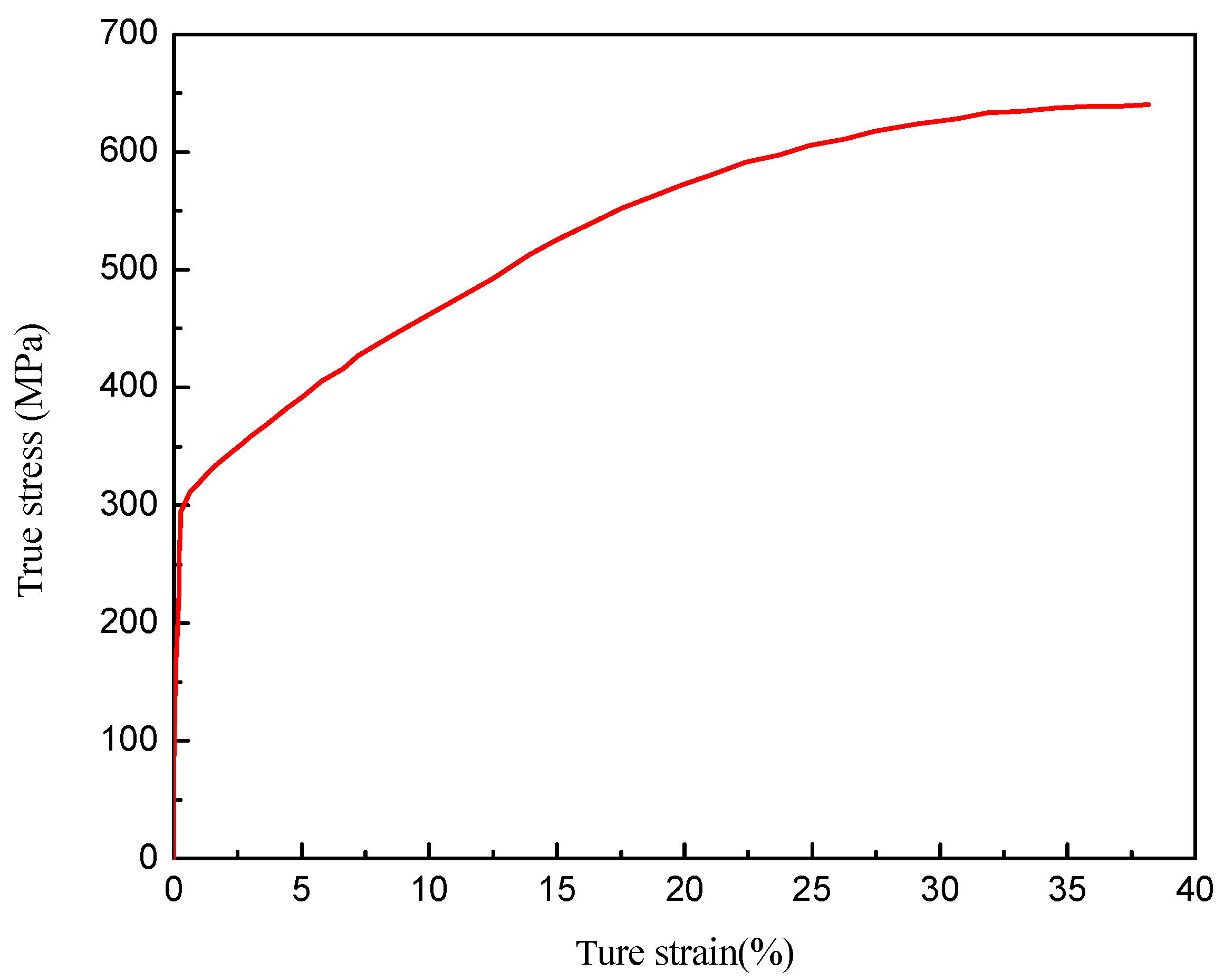
Table 1, and the true stress–strain curve of 316L is shown in
Figure 1.
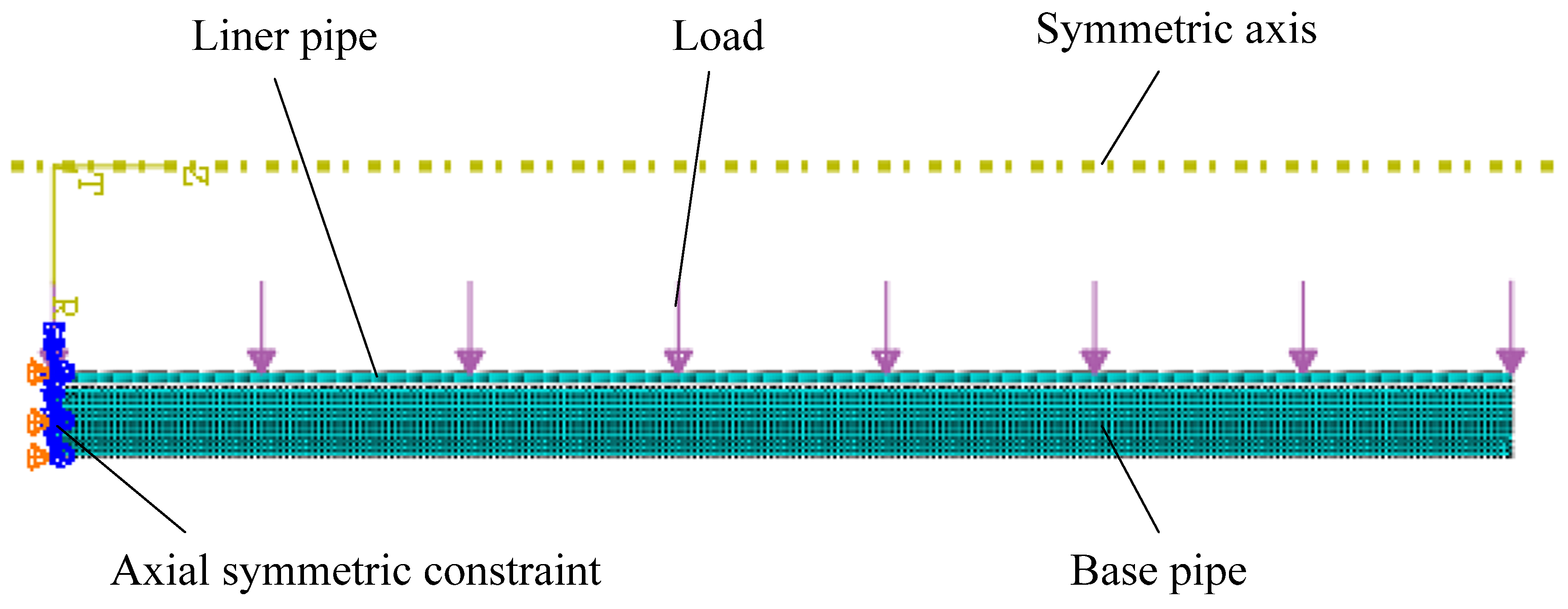
In the finite element modeling of hydraulic forming, based on the central axis symmetry characteristics of pipe structure and pressure distribution, it is simplified into a two-dimensional axisymmetric problem during finite element calculation; meanwhile, since the billet and bulging pressure are also symmetrical along the axis direction, only half of them are simulated in the axial direction. The constraint conditions are applied to the axial symmetry plane, and the axial displacement is constrained by the axial symmetry plane (i.e., the half model section). We apply constraint conditions to the axisymmetric plane, which constrains its axial displacement. The computational efficiency is improved through half model simulation; both the liner and base pipes use bilinear reduced integral axisymmetric quadrilateral elements (CAX4R). This unit type can effectively suppress the hourglass effect while ensuring calculation accuracy, and is suitable for analyzing large contact deformations of this type. In order to balance computational efficiency and accuracy, a differentiated grid density strategy was implemented: the base pipe basically only produces elastic deformation or a small amount of plastic deformation, and the grid is relatively sparse, with a global element size of about 2 mm; the liner pipe undergoes large plastic deformation, and the grid needs to be fine enough to capture the deformation gradient and contact state, so it is densified with a grid size of about 1 mm. Grid independence verification was carried out before and after modeling to confirm that the change in key output results (such as combining interface pressure) under the current grid density is small enough, and the grid partitioning scheme is reasonable. The Coulomb friction model is used to describe the friction behavior between the inner wall of the base pipe and the outer wall of the liner pipe. The contact property is tangential, the friction directionality is isotropic, and the friction coefficient value is 0.3. To verify the rationality of this value, parameter sensitivity analysis was conducted. The results showed that when the friction coefficient fluctuates within the range of 0.2 to 0.5, it has minimal impact on the prediction of residual contact stress, proving that the simulation results are insensitive to the friction coefficient value. The current setting is reasonable; the rebound analysis during the unloading phase uses a static implicit algorithm to ensure the accuracy of deformation prediction. The finite model established is shown in
Figure 2, and the debugged and optimized model is created for calculation.
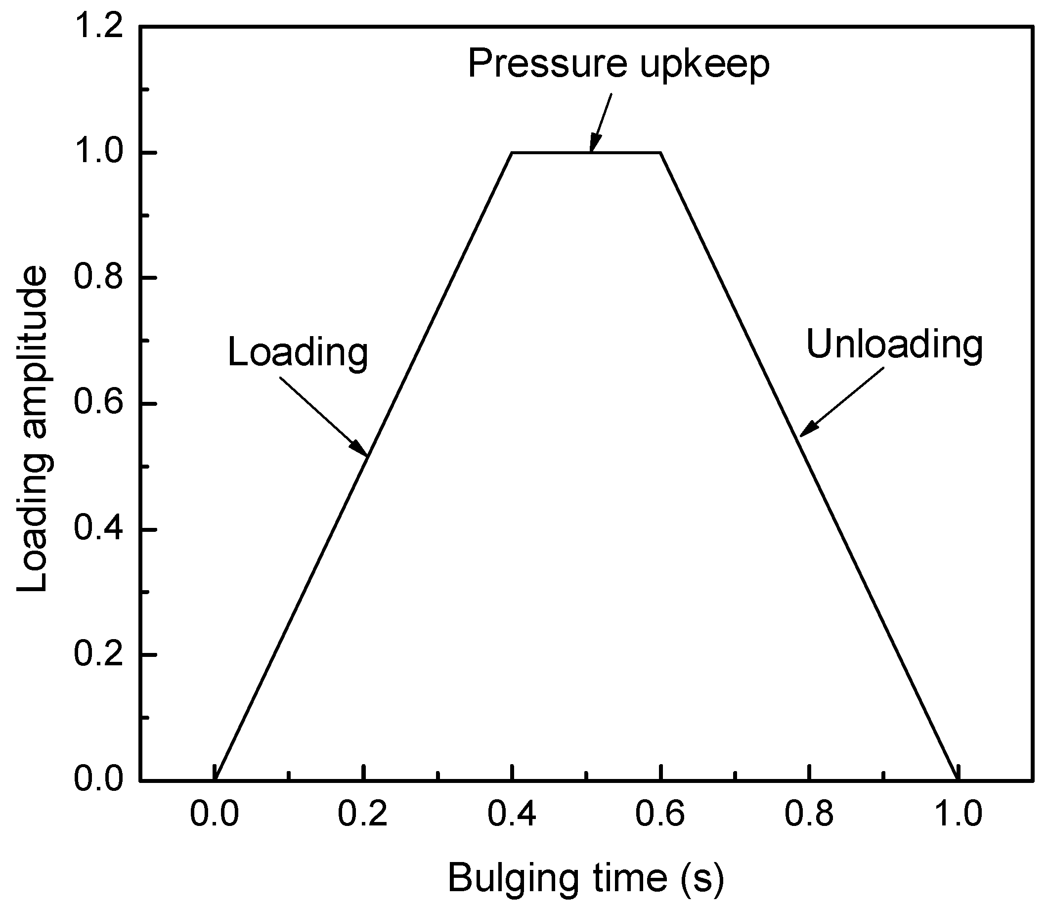
The loading path of bulging pressure (as shown in
Figure 3) during the bulging process. In the figure, the loading process is from 0 to 0.4 s, and the bulging pressure increases linearly with time; 0.4~0.6 s is the pressure holding process, and the pressure remains constant at the maximum bulging pressure; 0.6~1 s is the unloading process, and the bulging pressure linearly decreases from the maximum bulging pressure to 0, completing the unloading. The maximum bulging pressure during the experiment is 120 MPa. The pressure during the pressure holding stage is the maximum pressure during the bulging process, and the actual bulging pressure borne by the inner wall of the liner at a certain moment is the product of the amplitude at that moment and the maximum pressure.
To verify the effectiveness of the model proposed in this paper, the finite element simulation results were compared with experimental values [
13] (experimental verification based on a single reference dataset also has certain limitations). The lining pipe is a 316L stainless steel pipe with a diameter of 148 × 3 × 1000 mm, and the base pipe is an X70 steel pipe with a diameter of 200 × 24 × 1000 mm. The initial gap between the lining pipe and the base pipe is 2 mm. The mechanical properties of the pipe are shown in
Table 1.
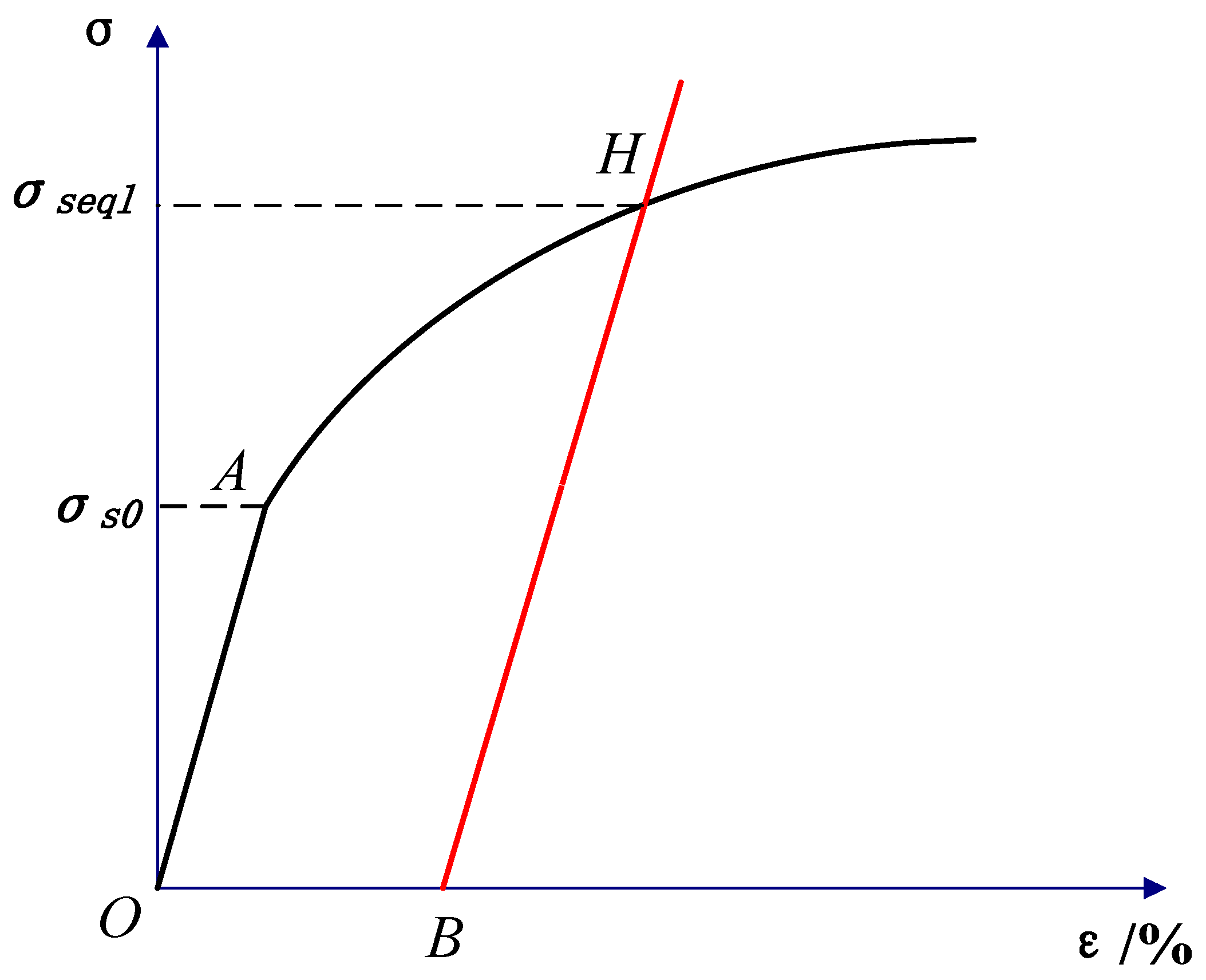
The graphical method for equivalent yield strength based on the true stress–strain curve of the material is shown in
Figure 4. Curve O-A-H represents the true stress–strain curve of the liner, point A represents the yield strength of the liner material, and a straight line passing through point B (strain
, where δ is the initial gap between the liner and the base pipe, and ro is the outer diameter of the liner) with a slope of the elastic modulus E1 of the liner intersects with curve O-A-H at point H. The stress value at point
H is taken as the equivalent yield strength
σseql of the liner. The true stress–strain curve of 316L is shown in
Figure 3.
Figure 5 and
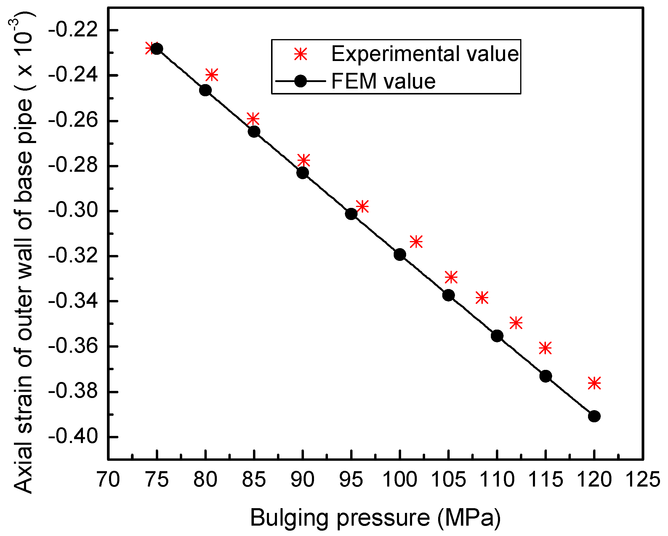
Figure 6 show the variation curves of axial strain and circumferential strain of the outer wall of the base pipe obtained under the aforementioned bulging conditions during the loading process. Obviously, the finite element simulation values are very close to the experimental values, with maximum relative errors of 3.89% and 1.77%, respectively. It can be seen that the finite element model of bimetallic tube hydraulic bulging established in this article is effective and fully meets the needs of engineering applications.
3. The Influence of Bulging Pressure on Hydraulic Forming of Bimetallic Composite Pipes
3.1. Determination of the Selection Range of Bulging Pressure
According to the theoretical derivation in reference [
14], the minimum bulging pressure
Pmin of bimetallic composite pipes is as follows:
The ultimate bulging pressure
Pemax at which only elastic deformation occurs in the base pipe is
The ultimate bulging pressure Ppmax for slight plastic deformation of the base pipe is
In the formula, El and Eb are the elastic modulus of the lining pipe and the base pipe; t is the wall thickness of the lining tube; that is,
, where Rbo and Rbi are the outer radius and inner radius of the base pipe; μL and μb are the Poisson’s ratios of the liner and base pipes, respectively; σsb the yield strength of the base pipe.
In this study, except for the bulging pressure, other model parameters are based on the data in
Section 2. According to the solution method for equivalent yield strength in the previous section, combined with
Figure 1 and
Figure 4, the equivalent yield strength of the liner tube
σseql is calculated to be 386.16 MPa. After calculation, the maximum bulging pressure range that the above-mentioned bimetallic composite pipe can composite is 112.3~183.9 MPa. Therefore, this article selects seven sets of values within the above range, namely 120 MPa, 130 MPa, 140 MPa, 150 MPa, 160 MPa, 170 MPa, and 180 MPa, as the maximum bulging pressure. The maximum bulging pressure will be referred to as bulging pressure in the following text.
3.2. The Influence of Bulging Pressure on the Deformation of Composite Pipes
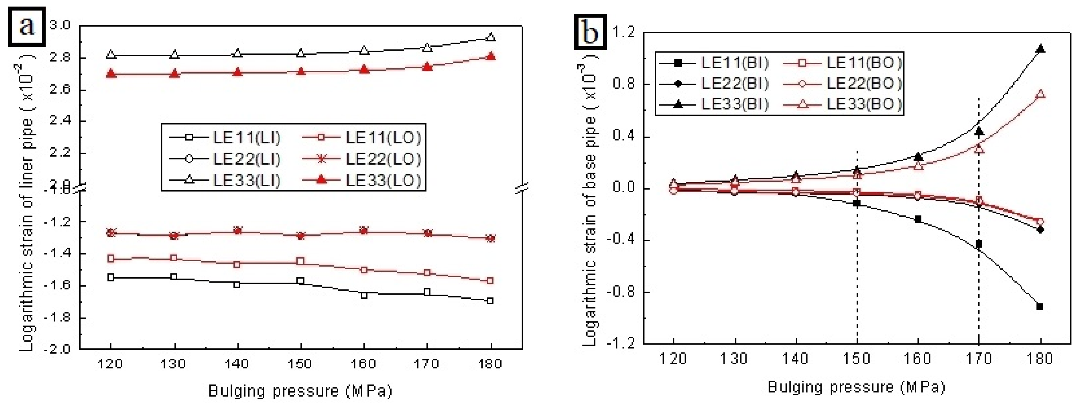
The influence curve of bulging pressure on the strain component of composite pipes is shown in
Figure 7. In the legend, 11, 22, and 33 represent the radial, axial, and circumferential directions of the composite pipe, respectively. LI represents the inner wall of the liner, LO represents the outer wall of the liner, BI represents the inner wall of the base pipe, and BO represents the outer wall of the base pipe.
From
Figure 7a, it can be seen that after the bulging process, the liner undergoes significant plastic deformation, with a large degree of expansion in the circumferential direction (LE33) of the liner, axial shortening, and radial thinning. Additionally, the circumferential and radial strains on the inner wall of the liner are greater than those on the outer wall, while the axial strain is the same. With the increase in bulging pressure, the absolute values of strain of the liner in three directions tend to increase; when the bulging pressure reaches 170 MPa, the strain tends to increase with the variation in bulging pressure.
As shown in
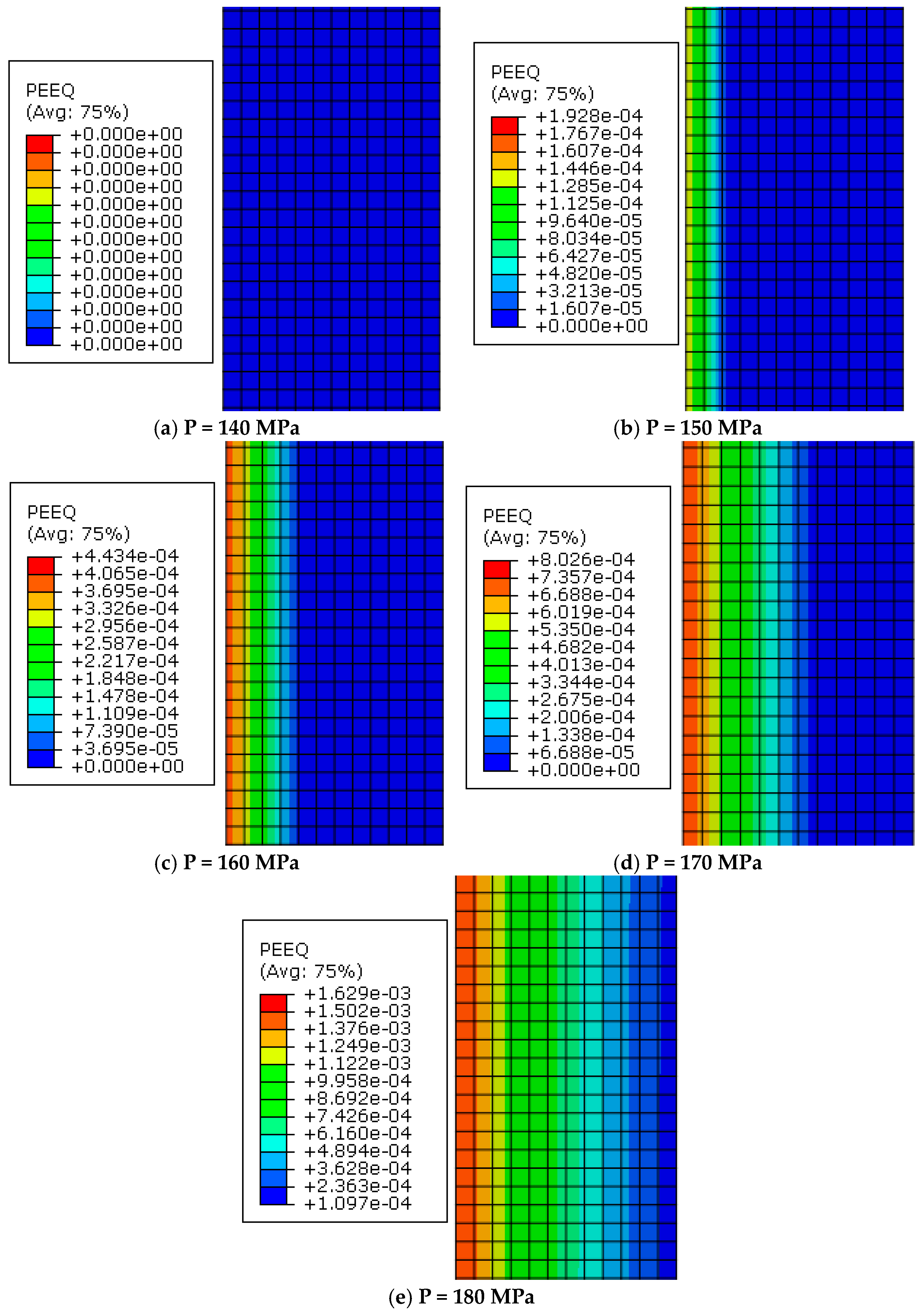
Figure 7b, with the increase in bulging pressure, the absolute value of the base pipe strain first gradually increases. When the bulging pressure increases to around 150 MPa, the absolute value of the base pipe strain increases at an accelerated rate, especially after the bulging pressure reaches 170 MPa, where the base pipe strain then sharply increases. The reason for the accelerated strain change in the base pipe is due to the occurrence of trace plastic deformation in the base pipe. As shown in
Figure 8a,b, when the bulging pressure reaches around 150 MPa, a small amount of plastic deformation begins to occur on the inner wall of the base pipe. As the bulging pressure increases, the plastic deformation gradually expands from the inner wall to the outer wall of the base pipe. When the bulging pressure increases from 170 MPa to 180 MPa, as shown in
Figure 8d,e, the plastic strain extends to the outer wall of the base pipe, causing plastic deformation in the thickness direction of the entire base pipe wall, resulting in a faster rate of strain increase, a sharp increase in the trend of pipe diameter expansion, and the risk of composite pipe cracking. This situation should be avoided during the bulging process.
3.3. The Influence of Bulging Pressure on the Rebound of Composite Pipes
Figure 9 shows the variation in circumferential strain of the inner wall of the base pipe with unloading time under different bulging pressures. As shown in the figure, as the unloading process progresses, the elastic deformation of the inner wall of the base pipe in the circumferential direction continues to recover, and the logarithmic strain in the circumferential direction decreases linearly. When the bulging pressure is low, only elastic deformation occurs on the inner wall of the base pipe. After complete unloading, due to the obstruction of the lining pipe, the elastic deformation of the base pipe cannot be fully restored, as shown in
Figure 10a; when the bulging pressure increases to 150 MPa, a trace amount of plastic deformation occurs on the inner wall of the base pipe. After complete unloading, the circumferential logarithmic strain and plastic strain basically coincide, indicating that the elastic deformation of the inner wall of the base pipe is basically fully restored; when the bulging pressure continues to increase to 180 MPa, as analyzed earlier, plastic deformation extends to the outer wall of the base pipe. When unloaded for about 0.36 s, the elastic deformation of the inner wall of the base pipe fully recovers; continuing unloading, the inner wall of the base pipe undergoes circumferential compressive elastic deformation due to the elastic recovery of the outer wall.
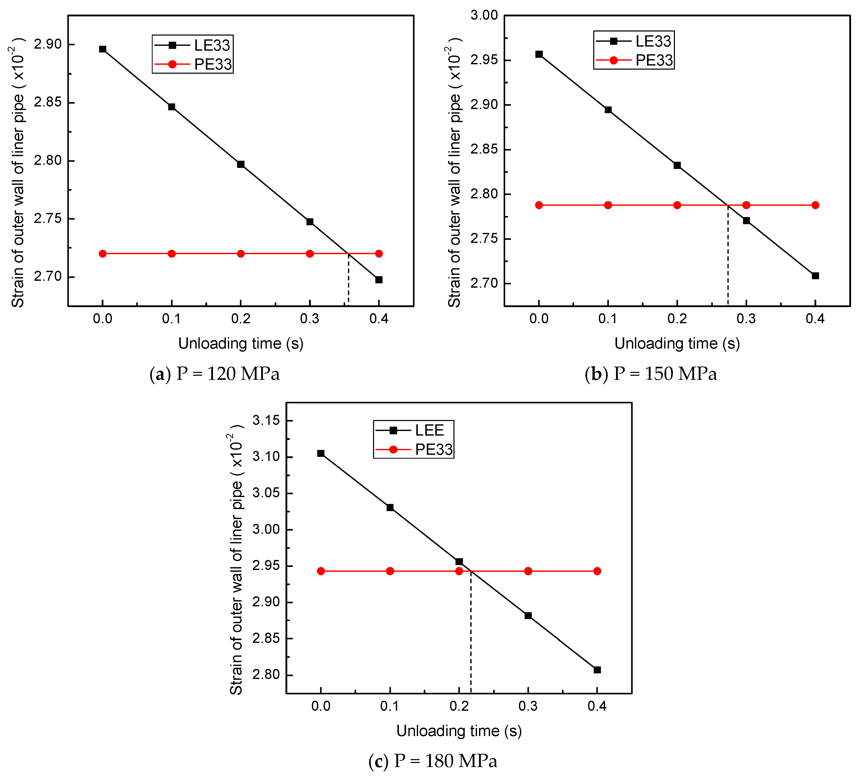
Figure 10 shows the variation in circumferential logarithmic strain and plastic strain of the outer wall of the liner with unloading time under different bulging pressures. As shown in the figure, as the unloading process progresses, the elastic deformation of the outer wall of the lining tube continues to recover; when unloaded to a certain point, the circumferential logarithmic strain curve intersects with the plastic strain curve, indicating that the elastic strain generated by the liner during loading has been fully restored; as the unloading process continues, due to the incomplete recovery of the elastic deformation of the base pipe, the liner undergoes compressive elastic deformation under the action of the elastic recovery of the base pipe, resulting in a lower logarithmic strain in the circumferential direction of the liner than the plastic strain. Comparing
Figure 10a–c, it can be seen that the greater the bulging pressure, the earlier the circumferential elastic deformation of the outer wall of the liner is fully restored. Under the action of the base pipe, the compressive elastic deformation of the liner is greater, and the residual contact pressure between the outer wall of the liner and the inner wall of the base pipe is also greater. This is also the fundamental reason why the residual contact pressure increases with the increase in bulging pressure in
Figure 11.
According to the above analysis, it can be seen that when the composite pipe only undergoes elastic deformation, as shown in
Figure 9a, its rebound after unloading is the difference in strain before and after unloading. When plastic deformation occurs in the composite pipe, if its elastic deformation is not fully restored after unloading, as shown in
Figure 9b, its rebound amount can still be represented by the strain difference before and after unloading; if the elastic deformation fully recovers during unloading, then in the subsequent unloading process, and when the elastic deformation continues to undergo compression under external force, its rebound should be represented by the difference between the logarithmic strain before unloading and the plastic strain after unloading.
Under different bulging pressures, the elastic deformation of the outer wall of the liner is fully restored during unloading, and reverse compressive plastic deformation occurs under the rebound of the base pipe during subsequent unloading (as shown in
Figure 10). Therefore, the rebound amount should be represented by the difference between the logarithmic strain before unloading and the plastic strain after unloading. For the inner wall of the base pipe, there are two situations mentioned above. Under the calculation conditions in this article, when the bulging pressure is less than 150 MPa, the rebound amount of the inner wall of the base pipe is represented by the strain difference before and after unloading. When the bulging pressure is greater than 150 MPa, it is represented by the difference between the logarithmic strain before unloading and the plastic strain after unloading.
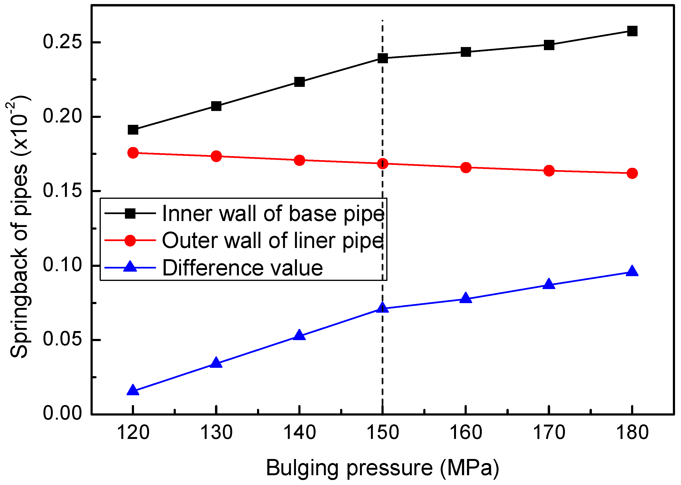
Based on the above analysis, the circumferential elastic recovery curves of the inner wall of the base pipe and the outer wall of the liner pipe with respect to the bulging pressure are shown in
Figure 12. As shown in the figure, the rebound of the inner wall of the base pipe is always greater than the elastic recovery of the inner wall of the liner pipe, and the difference in elastic recovery between the two gradually increases with the increase in bulging pressure. As shown in the figure, with the increase in bulging pressure, the elastic recovery of the inner wall of the liner gradually decreases, while the elastic recovery of the base pipe gradually increases. When the bulging pressure increases to the point where the inner wall of the base pipe begins to undergo plastic deformation (150 MPa), the elastic recovery of the inner wall of the base pipe reaches a turning point. Subsequently, as the bulging pressure increases, the rate of increase in the rebound of the inner wall of the base pipe decreases.
3.4. Effect of Bulging Pressure on Residual Contact Stress of Composite Pipes
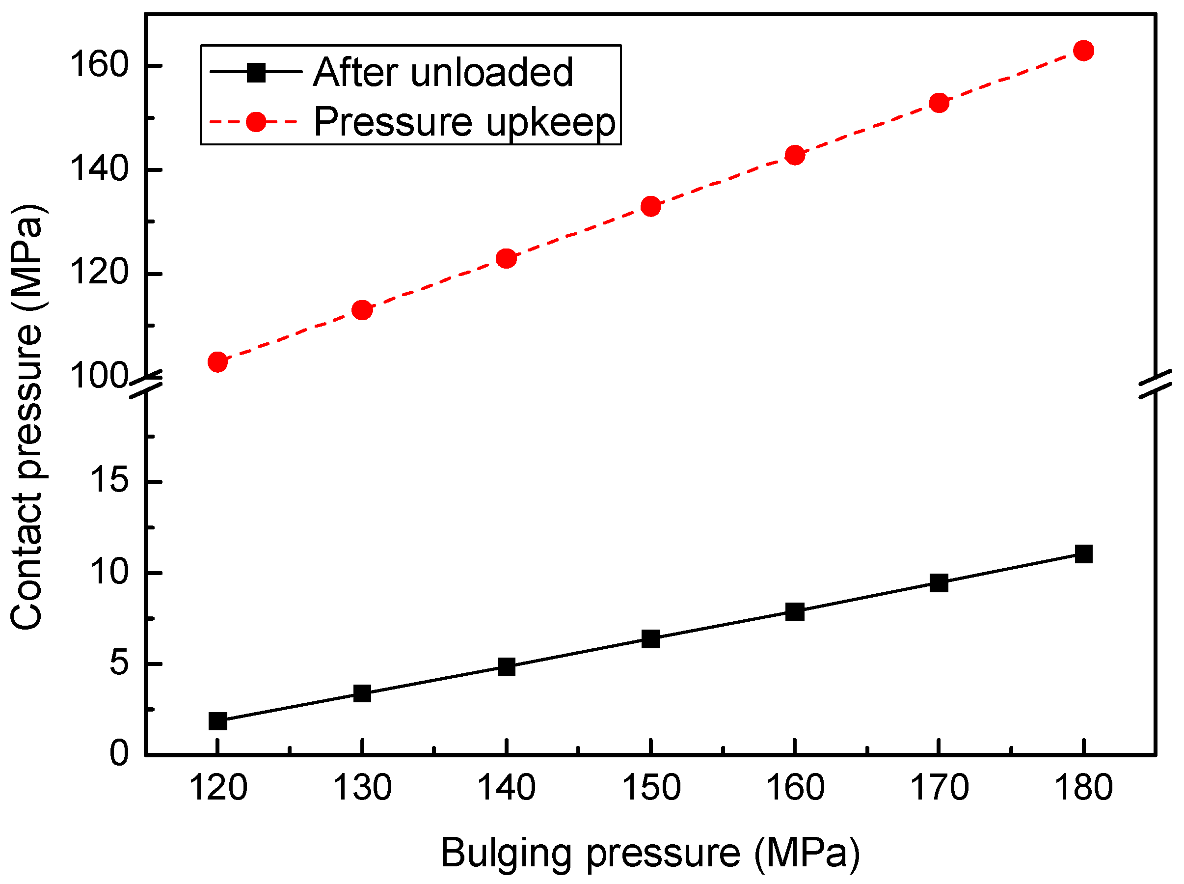
The residual contact pressure (bonding force) between the liner pipe and the base pipe after forming the bimetallic composite pipe is a key factor affecting the composite quality of the bimetallic composite pipe. The greater the residual contact pressure, the stronger the sealing performance and anti-stripping ability between the two pipes after bulging. The variation curve of residual contact pressure with bulging pressure is shown by the solid line in
Figure 11. The residual contact stress increases linearly with the increase in bulging pressure and does not change near the two critical values of bulging pressure.
From the dashed line in
Figure 11, it can be seen that the contact pressure between the two pipes during pressure holding also shows a linear increase trend with the increase in bulging pressure, but the slope of its increase is much greater than that of the increase in residual contact pressure. From these two curves, it can be seen that the decrease in contact pressure from holding pressure to complete unloading also increases linearly, with a slope of increase smaller than the slope of increase in contact pressure during holding pressure.
In summary, on the one hand, the residual contact stress between the liner and the base pipe increases continuously with the increase in bulging pressure, and the better the bonding ability between the two pipes. On the other hand, when the bulging pressure increases to a certain value, plastic deformation extends to the outer wall of the base pipe, and the trend of pipe diameter swelling increases sharply, which is very dangerous in the hydraulic bulging process of bimetallic pipes. Therefore, for safety reasons and to improve the bonding performance between the liner and the base pipe, the bulging pressure should be selected at the pressure value when the outer wall of the base pipe is about to undergo plastic deformation. In this case, the bulging pressure should be controlled at around 170 MPa.
