Article

Preparation and Performance Study of Self-Repairing External Anticorrosion Coating for Submarine Crude Oil Pipeline Based on Organic Corrosion Inhibitor

1
Sinopec Xinan Oil and Gas Field Branch, Chengdu 610095, China
2
Sinopec Key Laboratory of Development Technology of Sour Natural Gas Fields, Chengdu 610095, China
3
Petroleum Engineering School, Southwest Petroleum University, Chengdu 610500, China
4
State Key Laboratory of Oil and Gas Reservoir Geology and Exploitation, Southwest Petroleum University, Chengdu 610500, China
5
Yunnan Branch of PipeChina, Kunming 650200, China
6
Sinopec Zhongyuan Oilfield Company, Puyang 457000, China
*
Author to whom correspondence should be addressed.
Coatings 2025, 15(11), 1281; https://doi.org/10.3390/coatings15111281
Submission received: 30 September 2025 / Revised: 28 October 2025 / Accepted: 29 October 2025 / Published: 3 November 2025
(This article belongs to the Section Corrosion, Wear and Erosion)

Abstract

This study systematically investigates the corrosion inhibition mechanism of imidazoline (IM) and gallic acid (GA) within boron nitride-reinforced epoxy-phenolic composite coatings (GIBE) for subsea crude oil pipelines. Microstructural characterization via field emission scanning electron microscopy (FE-SEM) and energy-dispersive X-ray spectroscopy (EDS) confirms the formation of a molecularly dispersed system in acetone, wherein IM promotes interfacial passivation through amino-metal coordination bonding with the substrate. Electrochemical impedance spectroscopy (EIS) demonstrates a strong positive correlation between IM content and corrosion resistance. GA facilitates self-healing capacity by forming Fe3+-chelated barriers at localized defects (as verified by X-Ray photoelectron spectroscopy (XPS) analysis of Fe3+–GA complexes); however, its inherent hydrophilicity introduces microchannels, as evidenced by a 28.6% reduction in the water contact angle, which ultimately compromises the barrier performance at elevated concentrations. The optimized formulation (5 wt.% IM with 2 wt.% GA) exhibits protective performance in simulated seawater at 60 °C: after 7 days of immersion, the low-frequency impedance modulus (|Z|0.01Hz) reaches 6.28 × 10¹⁰ Ω·cm2 with no visible corrosion at scribed regions; after 28 days, |Z|0.01Hz remains above 1010 Ω·cm2, surpassing the service durability threshold of conventional epoxy coatings under high-temperature saline conditions. This work proposes a novel engineering approach for designing anti-corrosion coatings tailored to marine extreme environments.

1. Introduction

Petroleum energy serves as a cornerstone of modern society and is widely regarded as the “lifeblood of industry.” According to research estimates, global subsea oil reserves total 135 billion tons, accounting for approximately 45% of the world’s recoverable reserves—a substantial resource that cannot be overlooked [1]. Pipeline transportation remains one of the most economical methods for oil and gas delivery and is extensively used in offshore crude oil transmission [2]. Carbon steel, valued for its excellent mechanical properties and low cost, is the primary material used in subsea crude oil pipelines. In the complex and harsh marine environment, these pipelines are predominantly susceptible to external corrosion mechanisms such as concentration cell corrosion, microbiologically influenced corrosion, stress corrosion cracking, and oxygen corrosion, all of which significantly elevate the risk of corrosion-induced failure [3]. Furthermore, underwater pipeline repair involves considerable technical difficulties and high pollution control costs. As a result, stricter standards and requirements are imposed on the anti-corrosion quality of pipelines to avoid additional maintenance caused by corrosion. Currently, the three-layer polyethylene (3PE) coating system is widely adopted as the primary external anti-corrosion solution for in-service subsea pipelines. Among these, the coatings in direct contact with the pipe surface form one of the most essential core structures for ensuring effective corrosion protection.
The coating consists of a film-forming resin, functional fillers, pigments, solvents, and other additives, with functional fillers playing a critical role in determining the overall coating properties [4]. BN, recognized for its exceptional barrier properties, high electrical insulation, and excellent chemical/thermal stability, has emerged as a key functional filler in the development of novel anti-corrosion coatings designed for harsh marine environments [5]. Wu et al. developed BN/EP coatings by dispersing hydroxyl-modified hexagonal boron nitride (h-BN) into a water-based epoxy resin. After 70 days of immersion in a 3.5 wt.% NaCl solution, the value of |Z|0.01Hz was maintained at 107 Ω·cm2 [6]. Similarly, Zhao et al. fabricated PEI/BNNs/EP coatings by incorporating polyethyleneimine (PEI)-modified h-BN nanosheets into water-based epoxy, reporting an approximate 4-fold enhancement in corrosion resistance compared to pure epoxy coatings [7]. It should be noted, however, that the anti-corrosion mechanism of h-BN-based coatings primarily relies on a physical barrier effect, categorizing them as passive anti-corrosion systems.
With prolonged service and exposure to corrosive environments, coatings inevitably undergo failure phenomena such as localized damage and delamination. Under such conditions, coatings relying solely on a passive barrier mechanism become insufficient to provide effective corrosion protection. To address this functional limitation and enhance protective performance, researchers have increasingly focused on integrating corrosion inhibitors into coating systems to impart self-healing capabilities—a key advancement toward intelligent and proactive corrosion protection [8]. For instance, Diraki et al. electrochemically synthesized polyaniline coatings loaded with sodium octanoate (SC) and sodium dodecyl sulfate (SDS). Upon damage, these inhibitors are released and rapidly form an adsorbed protective film on the metal substrate [9]. Similarly, Liu et al. incorporated hydrothermally synthesized CeO2-GO nanomaterials into resin coatings, achieving synergistic protection through a combination of inhibitor-derived films and physical barrier effects [10].
Corrosion inhibitors can be categorized into three types based on their chemical composition: organic, inorganic, and composite inhibitors [11]. Among these, organic inhibitors have attracted significant attention due to their good compatibility with resin matrices and high inhibition efficiency. IM, as corrosion inhibitors, are widely employed in oil and gas applications and exhibit notable self-healing properties when incorporated into coatings. For example, Lin et al. demonstrated that IM inhibitors released at damaged sites adsorb onto the metal surface to form a protective film, effectively suppressing corrosion [12]. GA, which offers both corrosion inhibition and rust conversion capabilities, has also gained interest in coating development [13]. Fang et al. incorporated modified GA into an epoxy resin, resulting in a coating that exhibited a |Z|0.01Hz of 108 Ω·cm2 after 7 days of immersion in 3.5 wt.% NaCl solution, indicating excellent anti-corrosion performance [14]. Cao et al. developed an epoxy coating containing GA-based composite fillers, which demonstrated high corrosion resistance and a self-healing efficiency of 88.63% in 3.5 wt.% NaCl solution [15]. Furthermore, Liu et al. designed an epoxy coating using GA as a rust converter and graphene oxide as an anti-corrosion filler, which also showed promising corrosion inhibition and self-healing performance, with |Z|0.01Hz value reaching 106 Ω·cm2 [16].
In summary, while existing research on anti-corrosion coatings for subsea pipeline exteriors has made progress, most studies remain limited to single functional fillers or purely barrier-based protection mechanisms. There has been insufficient attention to the self-healing functionality required to mitigate coating damage over long-term service. Moreover, the development of external anti-corrosion coatings for subsea crude oil pipelines that integrate both high barrier resistance and active self-healing capabilities remains largely unexplored. Based on previous findings, coatings containing 2 wt.% A-BN have demonstrated excellent anti-corrosion performance [17]. Building on this, the present study introduces IM and GA into this matrix to develop a novel class of composite coatings that offer both corrosion inhibition and self-healing properties. The influence of IM and GA content on the comprehensive performance of the coating was systematically investigated. The microstructure, elemental composition, and spatial distribution of components within the coating were characterized using FE-SEM and EDS. The corrosion protection performance was evaluated via EIS to elucidate the correlation between inhibitor concentration and corrosion resistance. To assess self-healing capability, artificial defects were introduced into the coating using a precision blade. The macroscopic morphology of the damaged coating and the microscopic condition of the exposed substrate were examined through visual inspection and FE-SEM imaging. Additionally, XPS was employed to analyze the chemical composition of the healed regions, providing insights into the underlying self-healing mechanism.

2. Experimental

2.1. Raw Materials

In this work, all experimental materials and reagents were used as received without further purification. Their specifications and sources are summarized in Table 1.

2.2. Preparation of A-BN

The hexagonal boron nitride nanosheets (h-BNNs) were functionalized via silanization using γ-aminopropyltriethoxysilane (APTES), yielding silanized h-BNNs denoted as A-BN. A schematic illustration of the silanization process is provided in Figure 1. Based on preliminary findings from our research group, the silane modification of h-BNNs can be achieved with a minimal quantity of APTES [18]. The silanization procedure consisted of the following steps: exfoliation and dispersion, addition of ammonia solution, introduction of APTES, centrifugal washing, low-temperature drying, grinding and pulverization, and final product collection.
The required quantity of h-BNNs was first weighed and added to anhydrous ethanol at a mass ratio of 1:15 (h-BNNs to ethanol). Subsequently, h-BN nanosheets were prepared via ultrasonic-assisted liquid-phase exfoliation. Specifically, a mixture of h-BN powder and anhydrous ethanol was subjected to ultrasonic dispersion (AK-080SD, Yu Clean, Shenzhen Xin Kai Da Electronics Co., Ltd., Shenzhen, China) for 30 min in a 70 °C water bath to ensure uniform and complete exfoliation of h-BN nanosheets. Ammonia solution was then introduced into the mixture at a mass equivalent to 5% of the h-BNNs to catalyze the subsequent hydrolysis of APTES molecules. Finally, the silanization of h-BNNs was carried out via a sol–gel process. An amount of APTES equivalent to 3% of the h-BNNs mass was introduced into a separatory funnel and added dropwise to the h-BNNs-ethanol-ammonia mixture. After complete addition, the mixture was further subjected to ultrasonic dispersion under continuous water bath heating at 70 °C for 3 h to promote uniform covalent bonding between silane molecules and h-BNNs, resulting in the final A-BN product. All the above steps were performed in an ultrasonic bath maintained at a constant temperature of 70 °C. The A-BN were then purified by centrifugal washing: the product was centrifuged at 4500 rpm for four cycles to remove unreacted ammonia and APTES residues, and the precipitate collected from the bottom of the centrifuge tube was retained. Subsequently, the purified A-BN were dried in a constant-temperature oven at 50 °C for 48 h. Finally, the dried product was gently ground using an agate mortar to prevent agglomeration and ensure a uniform dispersion.

2.3. Preparation of Coatings

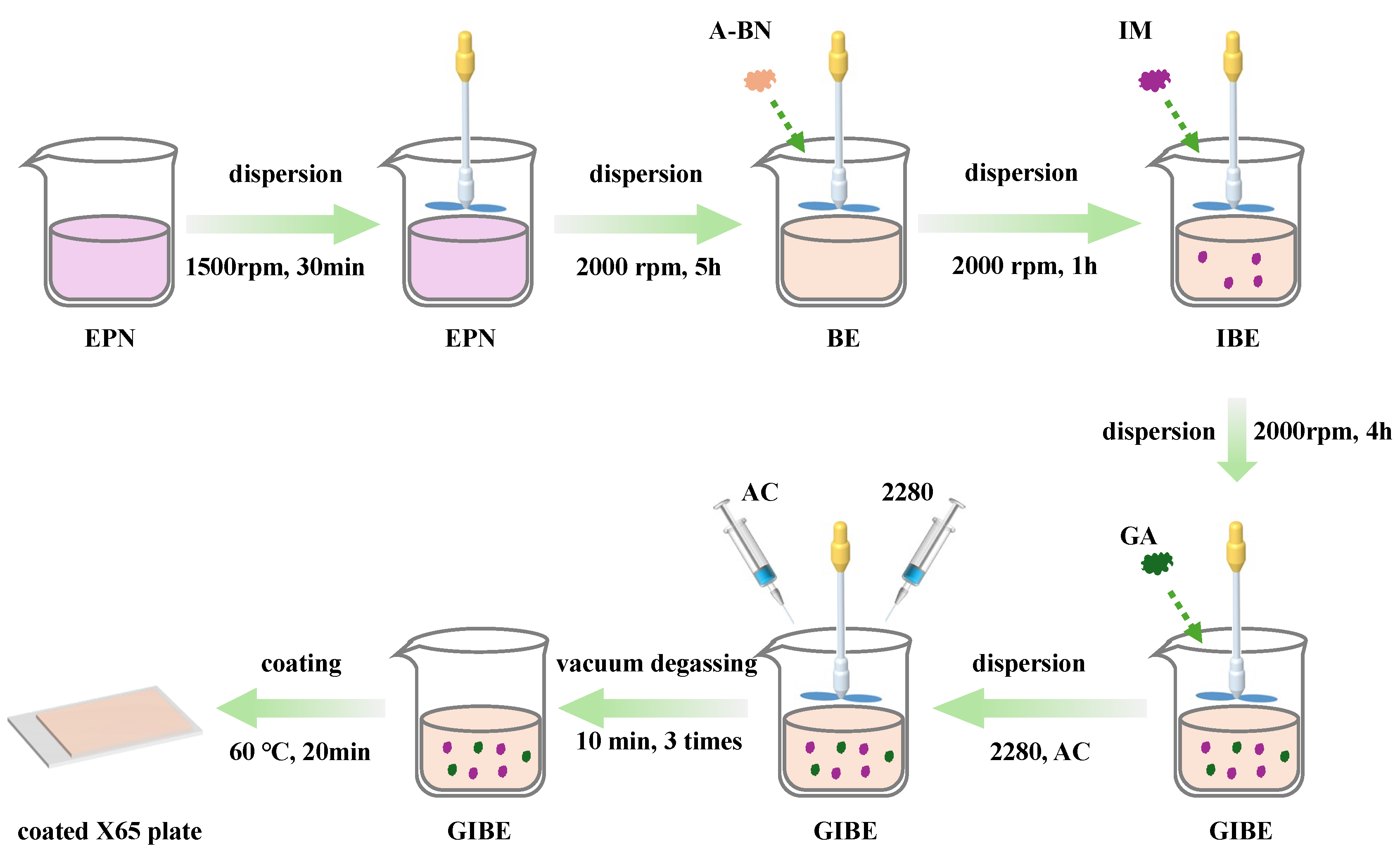
A self-healing anti-corrosion coating was prepared by uniformly dispersing functional fillers—A-BN, IM, and GA—together with acetone as the solvent and Ancamine 2280 as the curing agent into an EPN via mechanical stirring. A schematic diagram of the coating preparation process is shown in Figure 2. The entire procedure consisted of the following stages: resin dispersion, filler incorporation, solvent and curing agent addition, and vacuum degassing.
First, the epoxy-phenolic resin was stirred using a paddle mixer at 1500 rpm for 30 min to ensure homogeneous dispersion. Next, functional fillers including A-BN, IM, and GA were sequentially added to the EPN resin. Throughout the filler addition process, the mixture was continuously stirred at 2000 rpm. It should be noted that A-BN were incorporated at 2 wt.% relative to the EPN resin mass, with the addition carried out in multiple stages, each involving approximately 0.1 g of material [17]. Following the incorporation of A-BN, the mixture was stirred continuously for 5 h to ensure homogeneous dispersion. Similarly, after the addition of IM and GA, stirring was continued for 1 h and 4 h, respectively. In the third stage, acetone (as solvent) and Ancamine 2280 (curing agent) were introduced into the filler-resin mixture and blended at 500 rpm for 10 min to achieve a uniform consistency. The amounts of acetone and Ancamine 2280 added were 10 wt.% and 60 wt.% relative to the resin mass, respectively. Finally, the formulated coating was subjected to three cycles of vacuum degassing, each lasting 10 min.
Using the above procedure, a series of coatings with different filler compositions were prepared. The types and quantities of fillers used are summarized in Table 2 and Table 3. The coatings are designated based on the fillers incorporated: those containing “A-BN,” “A-BN-IM,” and “A-BN-IM-GA” are labeled as BE, IBE, and GIBE, respectively.

2.4. Preparation of Coating Characterization Sample

The coating was applied to X65 steel substrates (150 mm × 100 mm × 0.3 mm) via a coating knife using a sol–gel processing approach. Prior to coating, the steel surfaces were cleaned with petroleum ether and anhydrous ethanol to eliminate contaminants such as dust and oils. A uniform coating layer was then deposited using a 200 μm applicator, followed by thermal curing in a constant-temperature oven at 60 °C. Coating thickness was measured using a film thickness gauge (DTG-D2, Shenzhen Hongda Instrument Equipment Co., Ltd., Shenzhen, China). Specimens with a consistent coating thickness of 120 ± 5 μm were selected for subsequent anti-corrosion performance evaluation.

2.5. Material Characterization and Performance Testing

The microstructure and filler distribution within the coating were characterized using FE-SEM (Aprea S HiVac, Thermo Fisher Scientiffc, Waltham, MA, USA), while the corresponding elemental composition was determined by EDS (Aztec X-Max80, Oxford Instruments, Oxford, UK).
The corrosion protection performance of the coating was evaluated by EIS in an artificially simulated seawater solution at 60 °C. A conventional three-electrode system was employed on an electrochemical workstation (CS 350, CorrTest, Wuhan Corrtest Instruments Corp., Ltd., Wuhan, China), with a saturated calomel electrode (SCE, Shanghai Ledon Industrial Co., Ltd., Shanghai, China) as the reference electrode, a graphite electrode as the counter electrode, and the coated specimen (exposed area: 6.15 cm2) as the working electrode. EIS measurements were initiated once the fluctuation of the open-circuit potential (OCP) stabilized within 0.1 mV/min. The tests were performed with a sinusoidal amplitude of 20 mV relative to OCP, over a frequency range from 10−2 to 105 Hz. The obtained EIS data were fitted and analyzed using ZSimpWin software V2.0.
To assess the self-healing capability of the coating under mechanical damage, artificial defects were introduced on the coating surface using a craft knife with a blade width of 0.3 mm. The scratched samples were then immersed in simulated seawater at 60 °C for 7 days. After immersion, the self-healing performance was evaluated by examining the damaged areas through macroscopic visual observation and microscopic characterization. SEM and EDS were employed to analyze the microstructure and elemental distribution at the damaged interface, while XPS (K-alpha, Thermo Scientific, Waltham, MA, USA) was used to determine the chemical composition of corrosion products formed on the exposed metal surface. All XPS spectra were calibrated using the C–C bond reference at 284.8 eV.
The water absorption behavior of the coatings was also investigated in this work, in accordance with the testing procedure outlined in ASTM D870 [19]. Three replicate specimens were prepared for each coating formulation to ensure statistical reliability. Glass substrates were used for this test series. The initial mass of the clean glass substrate was recorded as m0. The coating was then applied to the glass substrate following the same procedure described previously for coating preparation. After complete curing, the total mass of the coated glass substrate was measured and recorded as m1. The coated specimens were subsequently immersed in artificial seawater at 60 °C for 28 days. After removal from the solution, surface moisture was carefully wiped off using filter paper, and the final mass was measured as m2. The water absorption rate was calculated using Equation (1).
w = m 2 m 1 m 1 m 0 × 100 %

3. Result and Discussion

In this study, the BE coating served as the baseline system, with varying concentrations of IM and GA fillers incorporated to systematically evaluate their effects on the coating’s corrosion protection performance and self-healing capacity. Based on the comprehensive performance test results, the optimal GIBM coating formulation was selected for further investigation. Subsequently, the mechanisms through which filler content influences coating performance were elucidated using SEM, EDS, and XPS analytical techniques.

3.1. Corrosion Resistance Properties of Coatings

3.1.1. EIS Tests of the Intact Coatings

To evaluate the effect of IM and GA content on the corrosion resistance of the coatings, specimens were immersed in artificial seawater at 60 °C for 7 days and subsequently characterized by EIS. The corresponding results are presented in Figure 3, Figure 4, Figure 5, Figure 6 and Figure 7. Based on the EIS findings, coatings demonstrating superior corrosion protection performance were selected for an extended 28-day immersion test to assess long-term protective capability, with the results shown in Figure 8.
Based on the EIS results, the effect of IM content on the anti-corrosion performance of IBE coatings and its optimal concentration were investigated, as shown in Figure 3. In the Nyquist plot (Figure 3a), the incorporation of fillers such as BN and IM significantly enlarges the capacitive arc radius compared to the pure EPN coating, indicating a marked improvement in corrosion resistance. Moreover, the capacitive arc radius of the IBE coating increases with rising IM content, demonstrating that IM further enhances the protective properties. The IBE coating with 5.0 wt.% IM exhibits the best corrosion resistance.
The |Z|0.01Hz is widely used as a semi-quantitative indicator for evaluating coating corrosion performance, where higher values correspond to better corrosion resistance [20]. As depicted in Figure 3b, the |Z|0.01Hz values of BE and IBE coatings are significantly higher than that of the pure EPN coating, confirming that the addition of BN and IM fillers substantially improves the anti-corrosion performance. Furthermore, the |Z|0.01Hz value of the IBE coating increases gradually with IM content, corroborating the enhancement in corrosion resistance with optimal IM loading.
For more accurate analysis, the EIS data were fitted using the equivalent circuit model shown in Figure 4a through ZSimpWin software. In this equivalent circuit, Rs, Rc, Rct, Qc, and Qdl represent solution resistance, coating resistance, charge transfer resistance, coating capacitance, and double-layer capacitance, respectively. Typically, Rc serves as an indicator of the coating’s barrier properties, while Rct shows positive correlation with corrosion resistance [18]. Therefore, both parameters can be employed to evaluate the coating’s anti-corrosion performance. The corresponding fitting results are presented in Figure 4b.
The analysis reveals that as the content of fillers such as BN and IM increases, the variations in Rc and Rct, align with the trends observed in the Nyquist plot’s capacitive arc radius and the |Z|0.01Hz values. Consistent with these findings, the corrosion resistance of IBE coatings shows progressive enhancement with increasing IM content. The optimal performance is achieved at 5.0 wt.% IM content, and this formulation is accordingly designated as the I5BE coating.
Building upon the optimized I5BE coating formulation, the influence of GA content on the corrosion resistance of GI5BE coatings was systematically investigated to determine the optimal GA concentration. The corresponding test results are presented in Figure 5. As evident from the Nyquist plots (Figure 5a), all GI5BE coatings exhibit significantly larger capacitive arc radii compared to the I5BE coating, demonstrating that GA incorporation substantially enhances the corrosion protection performance. Furthermore, the Bode plots (Figure 5b,c) reveal that both the |Z|0.01Hz and phase angle initially increase with GA content up to a certain threshold, followed by a subsequent decrease. This trend indicates that the corrosion resistance of GI5BE coatings is non-monotonic with GA loading, first strengthening and then weakening as concentration increases. Notably, the composite coating containing 2.0 wt.% GA demonstrates optimal corrosion protection performance, achieving the highest |Z|0.01Hz values and most stable phase angle characteristics among all tested formulations.
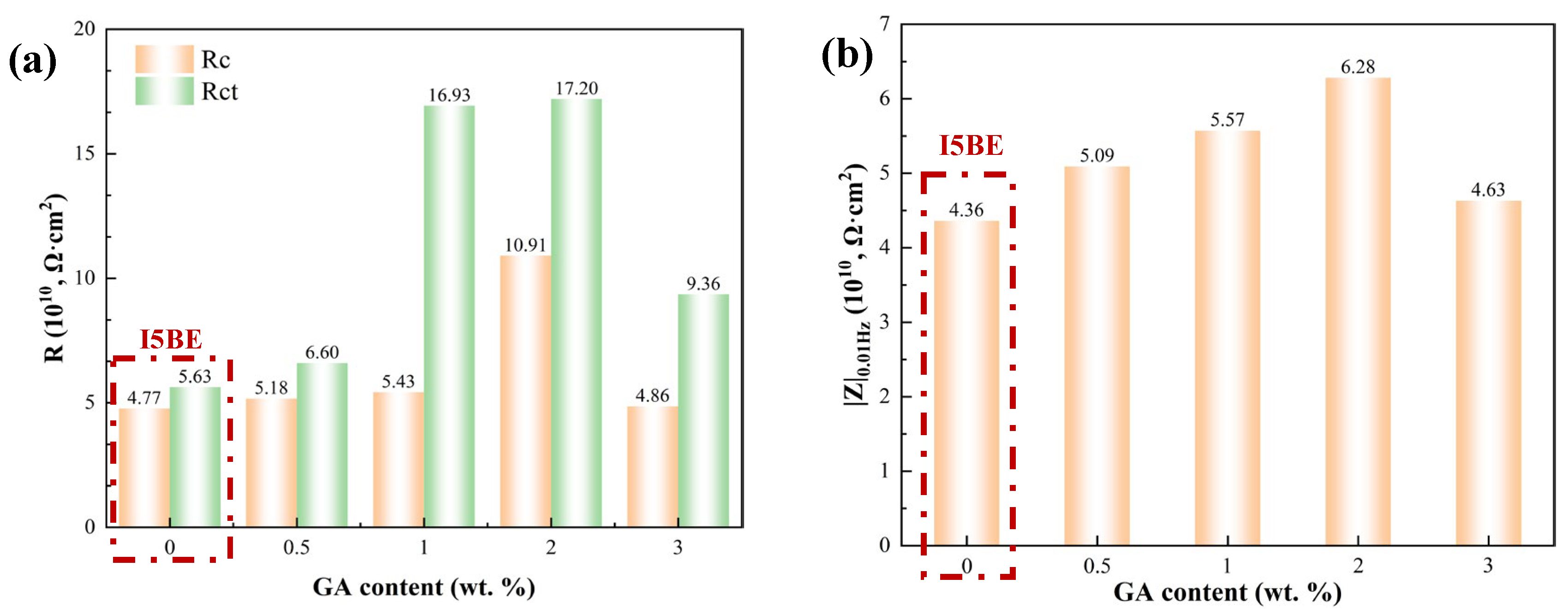
The EIS data of the GI5BE coatings were further fitted using the equivalent circuit model shown in Figure 4a. The resulting Rc and Rct values are presented in Figure 6a, revealing a clear trend where both parameters initially increase and then decrease with increasing GA content. This non-monotonic behavior is consistent with the variation observed in the |Z|0.01Hz, as shown in Figure 6b. Through collective analysis of the |Z|0.01Hz values, Rct, Rc, and capacitive arc radius, it is evident that the corrosion resistance of the GI5BE coating first strengthens and then weakens as the GA content rises. The optimal corrosion protection performance is achieved at a GA concentration of 2.0 wt.%, and this formulation is accordingly designated as the G2I5BE coating.
Based on the established effects of IM and GA content on corrosion resistance, the G2I5BE coating formulation demonstrated optimal performance. To evaluate its long-term reliability under corrosive conditions, a 28-day immersion test was conducted, with EIS results presented in Figure 7. The Nyquist plots (Figure 7a) show a gradual reduction in the capacitive arc radius of the G2I5BE coating with prolonged immersion time, indicating progressive deterioration of its protective properties. This trend is corroborated by the Bode plots (Figure 7b,c), where both the |Z|0.01Hz and phase angle exhibit consistent decline over the immersion period. These observations collectively indicate a systematic decrease in the coating’s corrosion resistance with extended exposure to the simulated marine environment.
The EIS data from the long-term immersion test of the G2I5BE coating were further interpreted using the equivalent circuit model depicted in Figure 4a. The fitted values of Rc and Rct are presented in Figure 8a. Both parameters exhibit a declining trend with prolonged immersion time; however, the rate of decrease stabilizes after 14 days. Notably, after 28 days of immersion, Rc and Rct remain above 1010 Ω·cm2. A consistent behavior is observed regarding the variation in |Z|0.01 Hz, as shown in Figure 8b. These results confirm that the G2I5BE coating retains excellent corrosion resistance even under extended exposure to aggressive conditions.

3.1.2. Water Absorption Tests of Intact Coatings

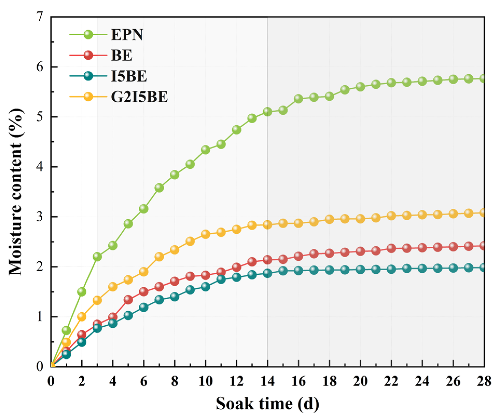
The incorporation of functional fillers including A-BN, IM, and GA significantly influences the water uptake behavior of coatings, which subsequently affects their corrosion protection performance. Based on the EIS evaluation results, four representative coating systems—EPN, BE, I5BE, and G2I5BE—were selected for a 28-day water absorption test following ASTM D870. The results are presented in Figure 9.
As shown in Figure 9, the water absorption behavior of all four coatings exhibits three distinct stages: initial rapid uptake, subsequent gradual uptake, and eventual saturation. The rapid absorption phase occurs within the first three days of immersion, during which water penetrates rapidly through inherent pores, microcracks, and other defective pathways in the coating matrix. On Day 1, the water absorption rates of I5BE and G2I5BE coatings were both below 0.5%. As immersion continued from Day 3 to Day 14, the coatings entered a slow absorption phase, characterized by a gradually declining absorption rate. From Day 14 to Day 28, the water absorption stabilized as the coatings reached saturation.
Analysis of the 28-day immersion data reveals the following final water absorption rates in descending order: EPN (5.77 wt.%), G2I5BE (3.08 wt.%), BE (2.42 wt.%), and I5BE (1.98 wt.%). These results indicate that the incorporation of A-BN and IM fillers significantly enhances the coating’s barrier properties, whereas the addition of GA increases water absorption to some extent, thereby moderately compromising the barrier performance.

3.2. Self-Healing Properties of Coatings

Based on the EIS results, which identified the G2I5BE coating as exhibiting optimal corrosion protection performance, four representative coatings—EPN, BE, I5BE, and G2I5BE—were selected to systematically investigate the influence of IM and GA fillers on the self-healing capability of the coatings. Artificial defects were introduced on the coating surfaces using a precision blade with a 0.3 mm tip width, followed by a 7-day immersion test in simulated seawater. The morphological evolution and chemical composition of the scratched regions were subsequently characterized by visual inspection, SEM, and XPS analysis to elucidate the self-healing mechanism imparted by IM and GA.

3.2.1. Macroscopic Morphology of Coating Damage

Macroscopic observations of the damaged regions on the EPN, BE, I5BE, and G2I5BE coatings are presented in Figure 10. As shown in Figure 10a,b, extensive reddish-brown corrosion products are visible along the scratches on both the EPN and BE coatings, indicating that neither system possesses self-healing capability. When the coating is damaged, corrosive species directly reach the metal substrate, inducing severe corrosion. In contrast, the I5BE coating containing 5.0 wt.% IM (Figure 10c) shows a notable reduction in rust formation along the scratch. This suggests that the incorporation of IM imparts a certain degree of self-healing functionality, significantly suppressing substrate corrosion, though some localized attack remains evident. Notably, the G2I5BE coating with 2.0 wt.% GA (Figure 10d) exhibits no visible rust deposits at the damaged area. This demonstrates that the addition of GA confers strong self-healing performance, effectively protecting the metal substrate and significantly inhibiting corrosion initiation even after mechanical damage.

3.2.2. Microscopic Morphology of the Base Metal at the Damage Site

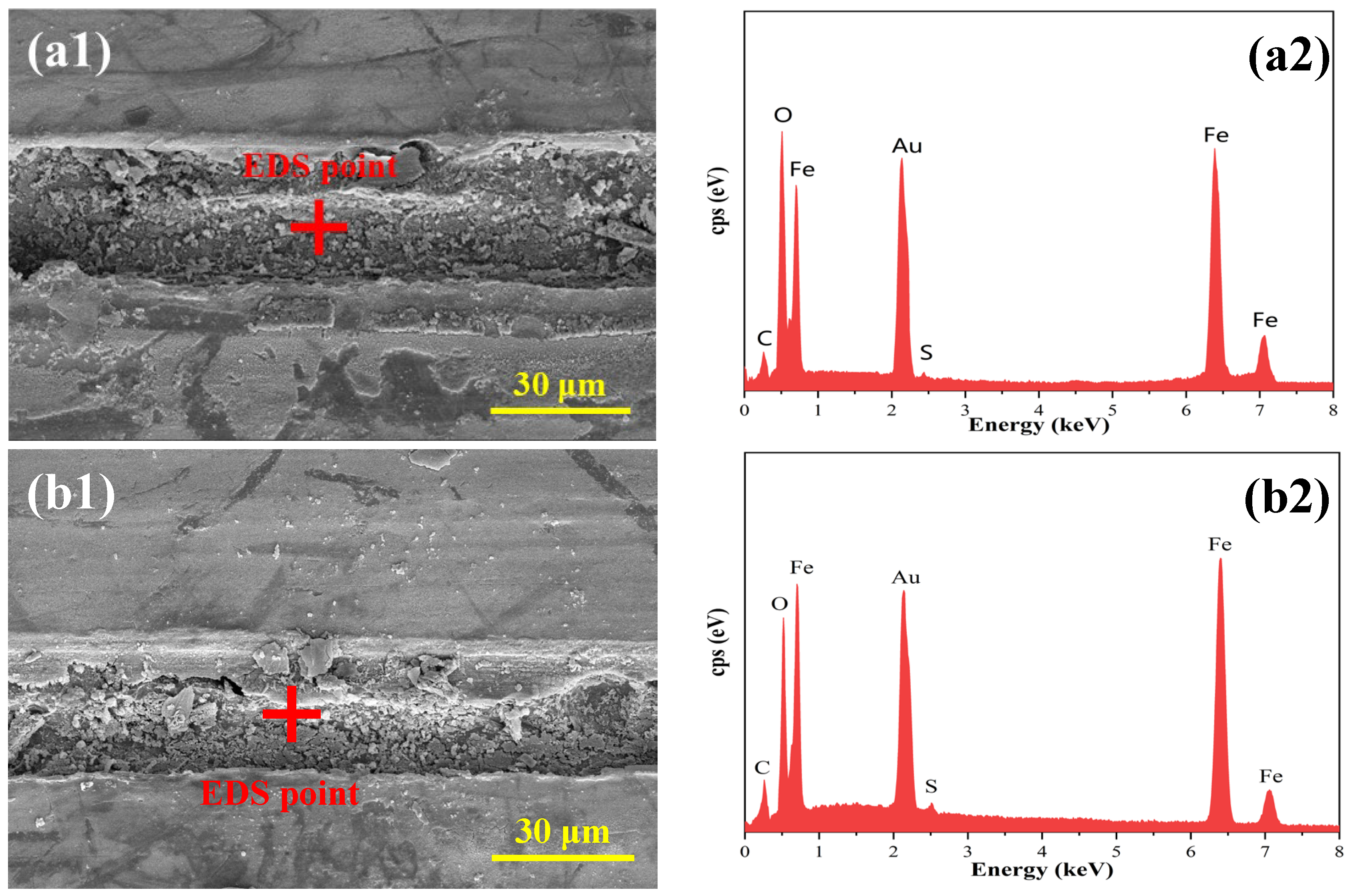
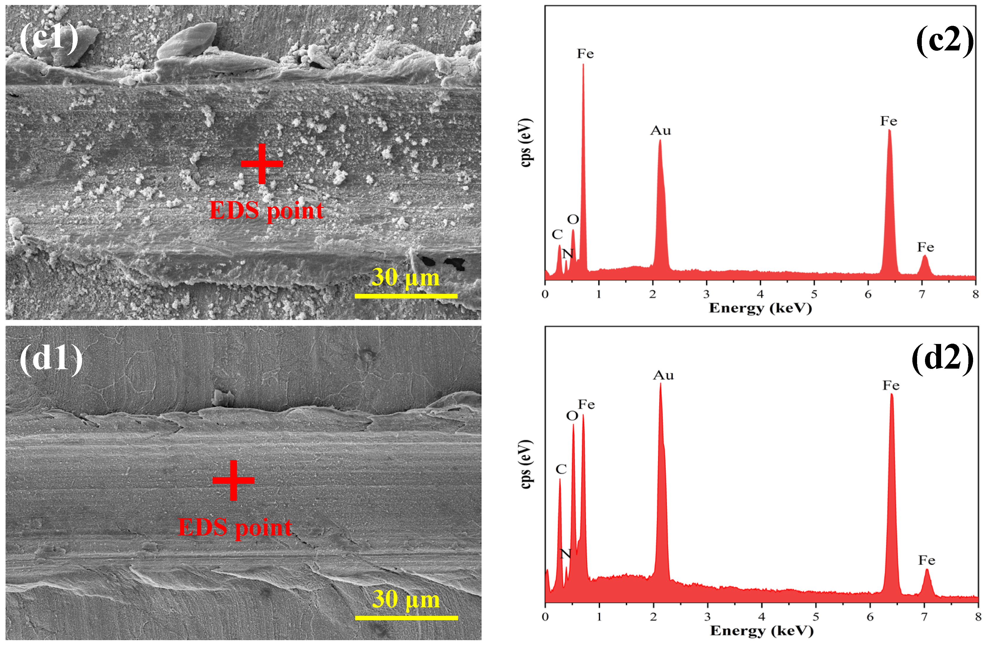
The damaged coating layers were carefully detached from the metal substrate surface using a utility knife, exposing the underlying substrate. The microstructure and elemental composition of the exposed metal regions beneath different coatings were characterized by FE-SEM and EDS, with the results presented in Figure 11.
As shown in Figure 11(a1,b1), the metal substrates under both the EPN and BE coatings display severe corrosion, with scratched surfaces entirely covered by thick, continuous corrosion products. When the coating contains 5.0 wt.% IM (I5BE, Figure 11(c1)), corrosion at the damaged interface is markedly suppressed, with only scattered, small-sized flake-like corrosion products observable on the surface. This indicates that IM incorporation contributes to a certain self-healing effect, though it remains insufficient to fully protect the metal substrate.
In contrast, with the further addition of 2.0 wt.% GA (G2I5BE coating, Figure 11(d1)), corrosion at the damaged area is effectively inhibited. No significant accumulation of corrosion products is observed, and the original scratch patterns remain clearly distinguishable. These results demonstrate that GA addition remarkably enhances the self-healing capability of the coating, providing near-complete protection to the metal substrate even in damaged regions.
The elemental composition of the exposed metal substrate at the damaged coating areas was analyzed by EDS, with results presented in Figure 11(a2–d2). As shown in Figure 11(a2,b2), the exposed substrate surfaces under the EPN and BE coatings are primarily composed of C, O, Fe, and S. Among these, C, O, and Fe are characteristic of iron-based corrosion products, while S originates from inorganic salts present in the simulated seawater environment. In contrast, the EDS spectra of the metal surfaces beneath the I5BE and G2I5BE coatings (Figure 11(c2) and (d2), respectively) reveal the presence of not only C, O, and Fe, but also N. This detection of nitrogen can be attributed to the adsorption and complexation of IM and GA molecules on the metal surface, supporting the hypothesis of an inhibitor-derived protective layer formation. These elemental findings align well with the observed self-healing behavior, confirming the role of IM and GA in enabling active corrosion protection at defect sites.

3.2.3. Compositional Analyses of Substrate Metal Surface Products at Breaks

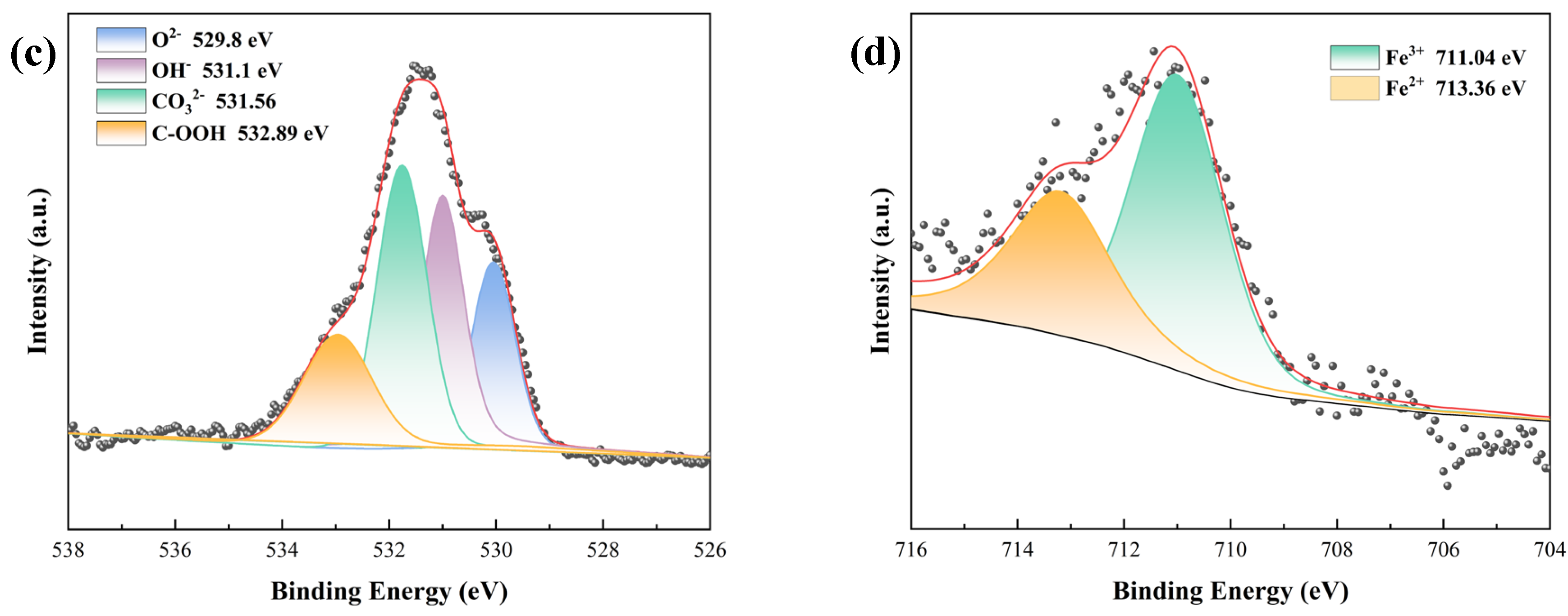
Based on the comprehensive evaluation of corrosion resistance and self-healing performance, the incorporation of IM and GA as functional fillers was demonstrated to significantly enhance both the protective properties and autonomous repair capability of the coatings. To elucidate the mechanistic role of IM and GA in improving coating performance, EPN and G2I5BE coatings were selected as representative systems for comparative analysis. The chemical composition of corrosion products formed on damaged metal substrates was characterized by XPS, with the corresponding results presented in Figure 12 and Figure 13.
The XPS analysis results of the corrosion products formed on the metal substrate at the damaged area of the EPN coating are presented in Figure 12. The XPS survey scan (Figure 12a) indicates that the exposed metal surface primarily consists of Fe, O, and C elements. The detected carbon is attributed to adventitious hydrocarbon contamination commonly encountered in XPS analysis and was excluded from further consideration. The high-resolution O 1s spectrum (Figure 12b) was deconvoluted into three characteristic peaks at 529.8 eV, 531.1 eV, and 531.56 eV, corresponding to CO32−, OH, and O2− species, respectively [21,22,23,24,25]. Furthermore, the high-resolution Fe 2p spectrum (Figure 12c) exhibits two major peaks at binding energies of 711.04 eV and 713.36 eV, assigned to Fe2+ and Fe3+ oxidation states [26,27].
The XPS analysis results of the corrosion products formed on the metal substrate at the damaged area of the G2I5BE coating are presented in Figure 13. The XPS survey scan (Figure 13a) reveals that the exposed metal surface primarily contains Fe, O, N, and C elements. As with the previous analysis, the detected carbon is attributed to adventitious hydrocarbon contamination and was excluded from further consideration. The high-resolution N 1s spectrum (Figure 13b) was deconvoluted into two characteristic peaks at 399.74 eV and 398.57 eV, corresponding to C-NH-C and C-NH2 functional groups, respectively [21,22]. These nitrogen species originate from the released IM molecules that have adsorbed onto the metal surface at the scratch site. The high-resolution O 1s spectrum (Figure 13c) exhibits four distinct peaks at binding energies of 529.8 eV, 531.1 eV, 531.56 eV, and 532.89 eV, assigned to O2−, OH, CO32−, and C-OOH species, respectively [23,25,28]. Comparative analysis with the EPN coating confirms that the C-OOH peak derives from the adsorption and protective film formation of GA molecules on the steel substrate. Furthermore, the high-resolution Fe 2p spectrum (Figure 13d) shows two primary peaks at 711.04 eV and 713.36 eV, corresponding to Fe2+ and Fe3+ oxidation states [26,27]. The significantly reduced intensity of these iron oxide peaks compared to the EPN coating further corroborates the effective corrosion inhibition provided by the IM and GA combination.

3.3. Morphologies and Elementary Composition of Coatings

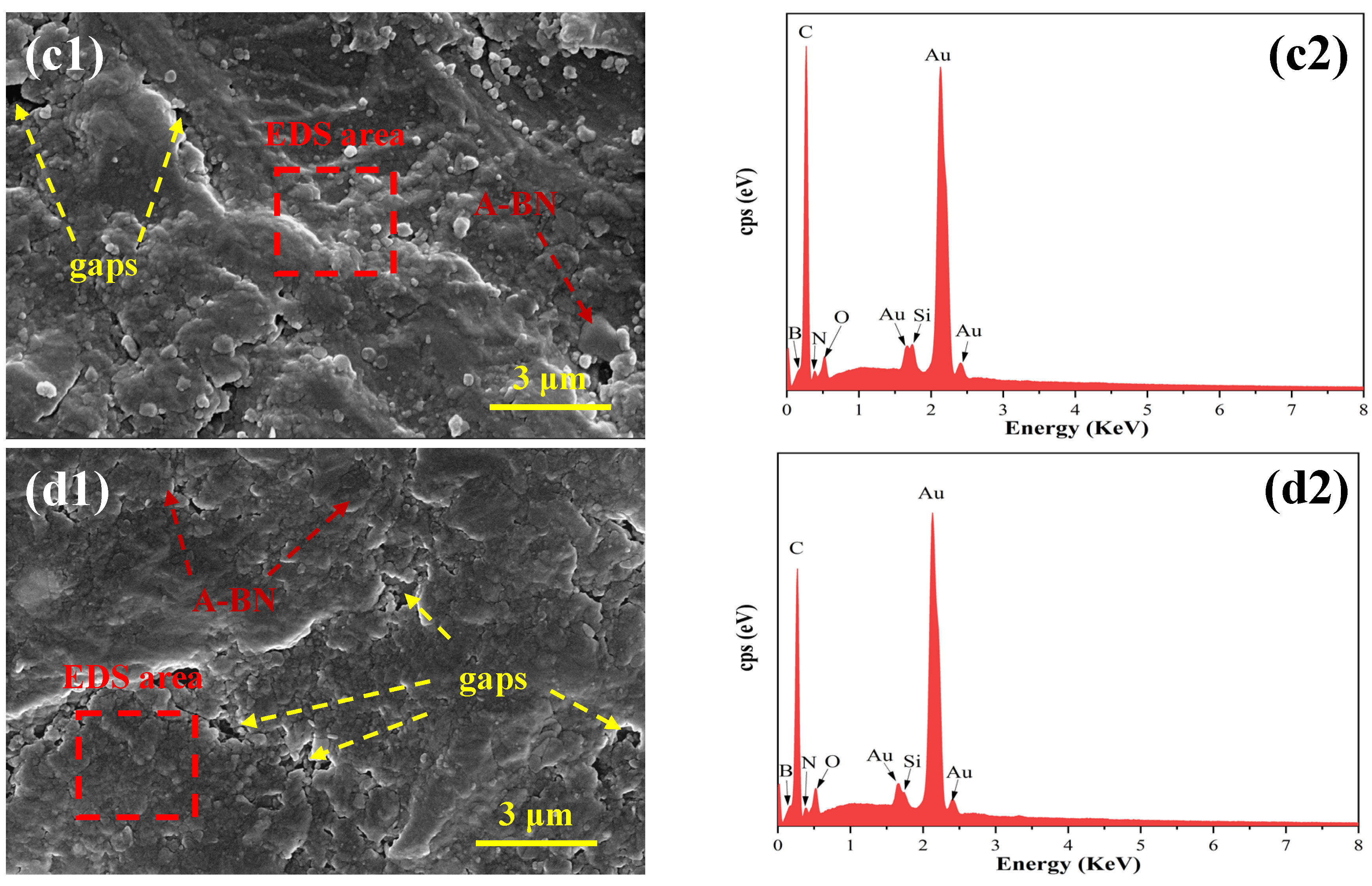
To examine the distribution and dispersion of functional fillers including A-BN, IM, and GA within the coating matrix, the surface morphology and elemental composition of different coating systems were characterized using FE-SEM and EDS. Since the filler content does not substantially alter their intrinsic state within the composite, three representative coatings—BE, I5BE, and G2I5BE, which demonstrated superior overall performance—were selected for detailed analysis. The EPN coating was used as the control group for comparative assessment. The corresponding results are presented in Figure 14.
The surface morphology of the different coatings is presented in Figure 14(a1–d1). The EPN coating (Figure 14(a1)) displays a relatively uniform and smooth surface, yet contains discrete pores that facilitate the penetration and accumulation of corrosive species. In contrast, the BE coating (Figure 14(a2)) exhibits significantly reduced defect density, although some porosity remains observable. Notably, the incorporation of IM and GA in the I5BE (Figure 14(a3)) and G2I5BE (Figure 14(a4)) coatings did not significantly alter the surface morphology compared to the BE coating. This observation indicates that the addition of these functional fillers maintains the structural integrity and dispersion state achieved with A-BN alone, without introducing additional defects or agglomeration.
The corresponding EDS elemental analysis results for the different coatings are presented in Figure 14(a2–d2). As shown in Figure 14(a2), the EPN coating primarily consists of C, N, and O elements. In contrast, the BE, I5BE, and G2I5BE coatings (Figure 14(b2–d2)) exhibit a consistent elemental profile containing C, N, O, and B, with the detected boron originating from the A-BN filler. This uniform distribution of boron throughout the coating matrix confirms the effective dispersion and integration of A-BN within the epoxy-phenolic system, while the consistent elemental patterns across the modified coatings indicate that the incorporation of IM and GA does not disrupt the fundamental composite structure.
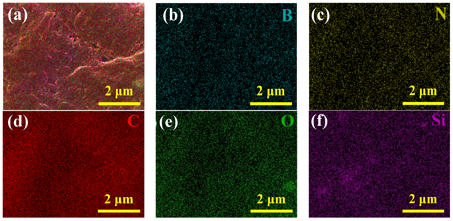
EDS analysis was performed to examine the elemental distribution within the G2I5BE coating, thereby evaluating the dispersion state of different functional fillers. The results are presented in Figure 15. The EDS spectrum (Figure 15a) confirms that the coating contains C, N, O, Si, and B as the primary elements. As shown in Figure 15b,f, both B and Si elements—characteristic of the A-BN filler—exhibit homogeneous distribution throughout the coating, indicating effective dispersion without significant aggregation. Furthermore, the spatial distributions of C, N, and O are displayed in Figure 15c–e. Given that the EPN resin and GA contribute mainly to C and O signals, while IM and the Ancamine 2280 curing agent introduce N in addition to C and O, the uniform mapping of these three elements suggests that IM, GA, and other organic components are also well-dispersed in the coating matrix. This homogeneous elemental distribution further confirms the successful integration of multiple functional fillers and the absence of localized agglomeration, thus validating the effectiveness of the coating preparation process.

4. The Influence of IM and GA Content on Coating Properties

The above findings demonstrate that incorporating IM and GA into BE coatings significantly enhances their corrosion resistance and confers self-healing functionality. These performance improvements are directly dependent on the concentrations of IM and GA added. Figure 16 schematically illustrates the protective mechanism of GIBE coatings, highlighting their enhanced corrosion resistance and autonomous self-healing capability.
As a typical two-dimensional material, A-BN possesses a high specific surface area and excellent compactness, demonstrating outstanding barrier properties against permeation of corrosive species such as H2O, O2, and Cl. When utilized as the sole functional filler in BE coatings, its interlocked stacking structure significantly prolongs the diffusion pathways of corrosive media through the coating matrix—a phenomenon known as the “labyrinth effect”—thereby substantially enhancing the corrosion resistance. However, intrinsic defects such as microcracks formed during the curing process and interfacial voids between A-BN and the EPN resin remain inevitable. These defects continue to expose the carbon steel substrate to corrosion risks, indicating that reliance solely on a physical barrier mechanism represents a passive protection strategy with inherent limitations.
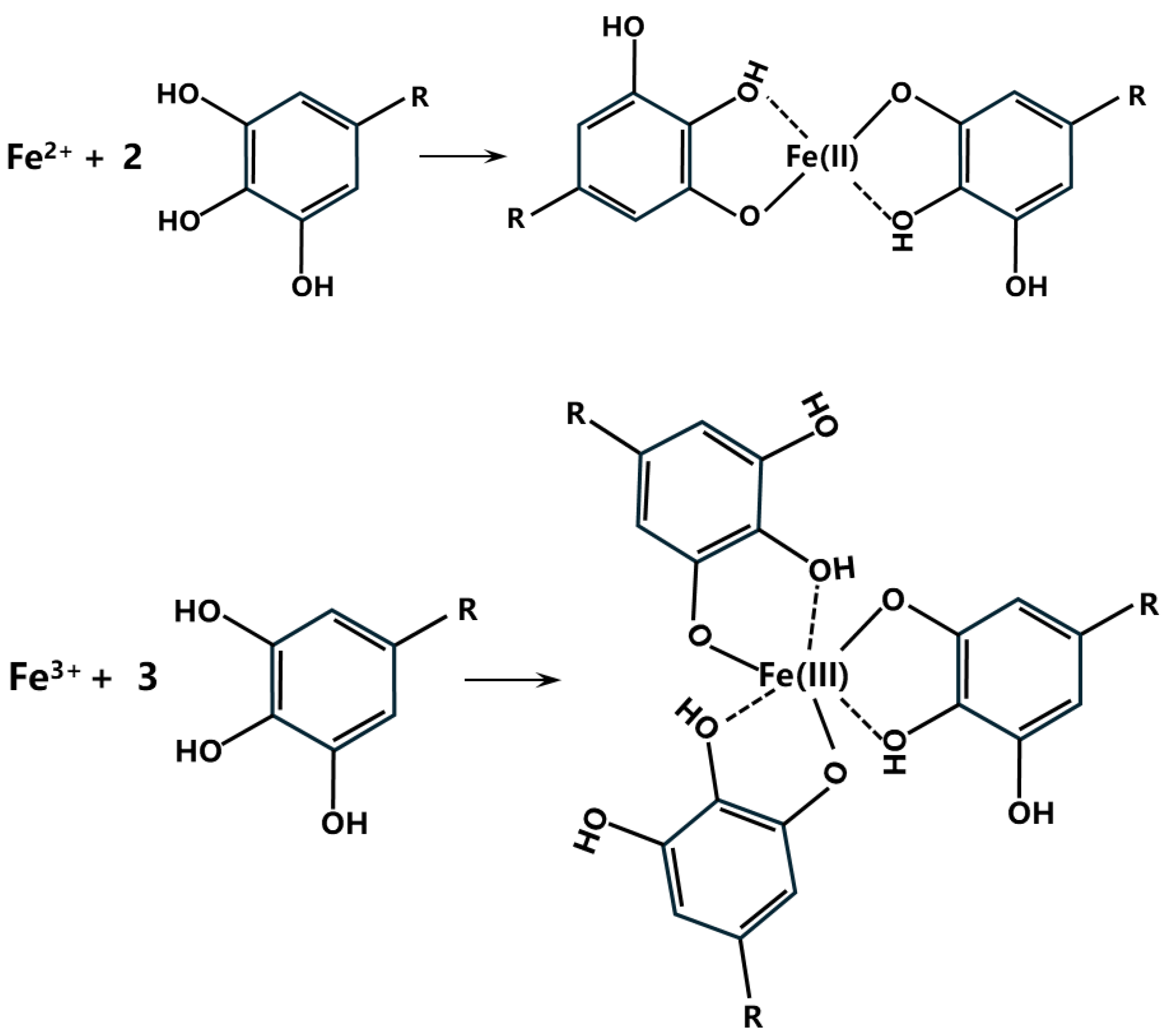
The incorporation of corrosion inhibitors represents one of the principal strategies for enhancing the active protection performance of organic coatings. After the introduction of IM into the BE coating system, the resulting IBE coating contains two functional components: A-BN and IM. While A-BN maintains its mechanical barrier function, IM further enhances the protective performance through its inherent hydrophobicity and corrosion inhibition capability. As a typical organic corrosion inhibitor, IM molecules adsorb onto the metal substrate via amino-metal coordination, forming a dense pre-passivation film that effectively suppresses the anodic dissolution of carbon steel, thereby significantly improving corrosion resistance [29]. With prolonged service, however, the coating gradually becomes saturated with water, allowing corrosive species to eventually reach the metal interface and pose corrosion risks. To address this limitation, GA was incorporated into the coating system. The ortho-phenolic hydroxyl groups in GA molecules can chelate with ferrous/ferric ions generated during corrosion, forming stable, insoluble complexes that deposit on the metal surface (shown in Figure 17). This protective layer effectively blocks the penetration of corrosive media and retards further corrosion, resulting in progressively enhanced protection with optimal GA content. Notably, both IM and GA exhibit good solubility in acetone, enabling uniform dispersion within the coating matrix during the preparation process and facilitating effective barrier and inhibition functions. However, as the ambient temperature increases, the water solubility of GA gradually rises. The dissolution of GA from its original locations creates microcavities that conversely provide additional pathways for corrosive media ingress. This phenomenon explains the observed decrease in corrosion resistance when GA content exceeds the optimal threshold (Figure 17).
With prolonged service, coating degradation—manifested as reduced barrier performance or even physical damage—becomes inevitable. When the coating is mechanically damaged, the underlying metal becomes directly exposed to the corrosive environment, substantially increasing the risk of localized corrosion. Under such conditions, the spatial barrier effect of A-BN becomes ineffective at the defect site due to the absence of a continuous coating matrix. However, IM and GA molecules from the intact coating regions adjacent to the damaged area migrate toward the exposed metal surface driven by concentration gradients. IM molecules adsorb onto the active metal surface through amino-metal coordination, forming a protective molecular film that suppresses anodic dissolution. Simultaneously, GA molecules react with iron ions generated at inadequately protected areas, forming stable, insoluble chelate complexes that deposit on the metal surface, providing supplementary sacrificial protection. On the exposed substrate, IM and GA operate to establish a dual passive layer through “chemical adsorption–physical barrier” interactions, thereby achieving autonomous self-healing of the coating and effectively restoring corrosion protection at the damaged interface.

5. Conclusions

The results above indicate that adding IM and GA to BE coatings significantly enhances the corrosion resistance of external anti-corrosion coatings for subsea 60 °C crude oil pipelines and confers certain self-healing properties. The following conclusions can be drawn:
(1) Regarding the corrosion protection performance, the incorporation of IM and GA into the BE coating significantly improves its corrosion resistance. The anti-corrosion properties exhibit a positive correlation with IM content, while showing a non-monotonic dependence on GA concentration—initially enhancing and then declining beyond an optimal threshold. The G2I5BE coating, formulated with 5 wt.% IM combined with 2 wt.% GA, demonstrates optimal corrosion protection performance among all investigated systems.
(2) Regarding the self-healing properties of the coating, doping IM and GA into the BE coating endows it with certain self-healing capabilities. When the BE coating contains 5 wt.% IM and 2 wt.% GA, the damaged G2I5BE coating exhibits no significant corrosion traces at the damaged site during artificial seawater corrosion at 60 °C.
(3) The presence and dispersion form of adsorbent corrosion inhibitors significantly enhance the coating’s corrosion resistance and self-healing properties. Due to the high solubility of IM and GA in acetone, they can be uniformly dispersed throughout the coating matrix during preparation, thereby markedly improving the coating’s corrosion resistance. However, GA’s solubility in hot water causes the coating to develop holes at its original location when exposed to water corrosion environments over extended periods. This increases pathways for corrosive media penetration, consequently reducing the coating’s corrosion resistance.

Author Contributions

Conceptualization, Y.Y. (Yongbo Yan) and J.W.; Data curation, J.Z. and J.L. (Jihui Leng); Formal analysis, X.L., Q.M. and P.X.; Methodology, J.L. (Jun Li) and S.W.; Project administration, D.F. and M.L.; Software, Y.Y. (Yinchun Yuan) and P.J.; Writing—original draft, J.R. and L.L.; Writing—review and editing, X.S. All authors have read and agreed to the published version of the manuscript.

Funding

National Major Special Project Plan for 2025: Comprehensive Demonstration of Smart Gas Field Construction, 2025ZD1408800.

Institutional Review Board Statement

Not applicable.

Informed Consent Statement

Not applicable.

Data Availability Statement

The original contributions presented in this study are included in the article. Further inquiries can be directed to the corresponding authors.

Conflicts of Interest

Authors Jing Zhou, Yongbo Yan, Jirong Wu, Qinghua Meng, Peng Xiang, Jun Li, Danyang Feng, Mingxing Liu, Yinchun Yuan, Pengfei Jia, Juan Ren, Lianggui Liu and Xuezhi Shi were employed by the company Sinopec Xinan Oil and Gas Field Branch. Authors Jihui Leng and Xin Liu were employed by the Yunnan Branch of PipeChina. Author Shutao Wang was employed by Sinopec Zhongyuan Oilfield Company. The remaining authors declare that the research was conducted in the absence of any commercial or financial relationships that could be construed as a potential conflict of interest.

References

  1. Li, Z.; Li, Q. Balancing Submarine landslides and the Marine Economy for Sustainable Development: A review and future prospects. Sustainability 2024, 16, 6490. [Google Scholar] [CrossRef]
  2. Tarakhtiyeva, G.K. Methods for transporting oil and gas. Acad. Res. Educ. Sci. 2022, 3, 1004–1008. [Google Scholar] [CrossRef]
  3. Ma, Y.; Zhang, Y.; Zhang, R.; Guan, F.; Hou, B.; Duan, J. Microbiologically influenced corrosion of marine steels within the interaction between steel and biofilms: A brief view. Appl. Microbiol. Biotechnol. 2020, 104, 515–525. [Google Scholar] [CrossRef] [PubMed]
  4. De Vargas, V.H.; Marczak, L.D.F.; Flôres, S.H.; Mercali, G.D. Advanced technologies applied to enhance properties and structure of films and coatings: A review. Food Bioprocess Technol. 2022, 15, 1224–1247. [Google Scholar] [CrossRef]
  5. Yang, X.; Zhang, R.; Pu, J.; He, Z.; Xiong, L. 2D graphene and h-BN layers application in protective coatings. Corros. Rev. 2021, 39, 93–107. [Google Scholar] [CrossRef]
  6. Wu, Y.; He, Y.; Zhou, T.; Chen, C.; Zhong, F.; Xia, Y.; Xie, P.; Zhang, C. Synergistic functionalization of h-BN by mechanical exfoliation and PEI chemical modification for enhancing the corrosion resistance of waterborne epoxy coating. Prog. Org. Coat. 2020, 142, 105541. [Google Scholar] [CrossRef]
  7. Zhao, H.; Ding, J.; Liu, P.; Yu, H. Boron nitride-epoxy inverse “nacre-like” nanocomposite coatings with superior anticorrosion performance. Corros. Sci. 2021, 183, 109333. [Google Scholar] [CrossRef]
  8. Zhao, X.; Jiang, D.; Ma, L.; Zeng, X.; Li, Z.; Huang, G. Corrosion effects and smart coatings of corrosion protection. Coatings 2022, 12, 1378. [Google Scholar] [CrossRef]
  9. Diraki, A.; Omanovic, S. Smart PANI/epoxy anti-corrosive coating for protection of carbon steel in sea water. Prog. Org. Coat. 2022, 168, 106835. [Google Scholar] [CrossRef]
  10. Liu, X.; Liu, R.; Li, T.; Liu, Y.; Liu, L.; Lyu, K.; Shah, S.P. Research on the anticorrosion properties of CeO2-GO/EP nanocomposite coating in simulated sea water. Polymers 2021, 13, 2072. [Google Scholar] [CrossRef]
  11. Al-Amiery, A.A.; Isahak, W.N.R.W.; Al-Azzawi, W.K. Corrosion inhibitors: Natural and synthetic organic inhibitors. Lubricants 2023, 11, 174. [Google Scholar] [CrossRef]
  12. Lin, B.; Wang, J.; Zhang, H.; Wang, Y.; Zhang, H.; Tang, J.; Hou, J.; Zhang, H.; Sun, M. Self-healing performance of ethyl-cellulose based supramolecular gel coating highly loaded with different carbon chain length imidazoline inhibitors in NaCl corrosion medium. Corros. Sci. 2022, 197, 110084. [Google Scholar] [CrossRef]
  13. Lei, Y.; Xiao, W.; Peng, H.; Yu, P.; Cai, X.; Luan, Z.; Deng, S.; Wang, S. An integrated epoxy rust conversion coating: Its anticorrosion properties and rust conversion mechanism. J. Alloys Compd. 2021, 853, 157005. [Google Scholar] [CrossRef]
  14. Fang, S.; Chen, K.; Yao, H.; Cao, Y.; Guo, S.; Wang, L.; Wang, Y.; Yu, S.; Wang, N. Preparation of gallic acid intercalated layered double hydroxide for enhanced corrosion protection of epoxy coatings. Coatings 2023, 13, 128. [Google Scholar] [CrossRef]
  15. Cao, L.; Wang, W.; Cheng, J.; Wang, T.; Zhang, Y.; Wang, L.; Li, W.; Chen, S. Synergetic inhibition and corrosion-diagnosing nanofiber networks for self-healing protective coatings. ACS Appl. Mater. Interfaces 2023, 15, 48645–48659. [Google Scholar] [CrossRef]
  16. Liu, J.; Wu, Y.; Yan, Y.; Wang, F.; Zhang, G.; Zeng, L.; Ma, Y.; Li, Y. Preparation and Performance Study of Graphene Oxide Doped Gallate Epoxy Coatings. Materials 2025, 18, 3536. [Google Scholar] [CrossRef]
  17. Shi, H.; Liu, W.; Liu, C.; Yang, M.; Xie, Y.; Wang, S.; Zhang, F.; Liang, L.; Pi, K. Polyethylenimine-assisted exfoliation of h-BN in aqueous media for anticorrosive reinforcement of waterborne epoxy coating. Prog. Org. Coat. 2020, 142, 105591. [Google Scholar] [CrossRef]
  18. Yan, Y.; Liao, K.; Hu, J.; Qin, M.; He, T.; Ou, T.; Fan, Y.; Leng, J.; He, G. Effects of h-BN content and silane functionalization on thermal conductivity and corrosion resistance of h-BN/EPN coating. Surf. Coat. Technol. 2024, 476, 130185. [Google Scholar] [CrossRef]
  19. Zhao, Y.; Wang, J.; Su, F.; Hu, L.; Wu, Q.; Qi, W.; Zhang, T.; Wang, F. Hydrogen embrittlement susceptibility of Ti-6Al-4V alloys fabricated by electron beam melting in simulated deep-sea environment. Corrosion 2024, 80, 24–40. [Google Scholar] [CrossRef]
  20. Charis, G.; Patel, B.; Rashama, C.; Nyamunda, B. Progress towards the standardization of test parameters and protocols for evaluating densified fuel products. Paliva 2024, 16, 16–29. [Google Scholar] [CrossRef]
  21. Pistone, A.; Scolaro, C.; Visco, A. Mechanical properties of protective coatings against marine fouling: A review. Polymers 2021, 13, 173. [Google Scholar] [CrossRef]
  22. Dementjev, A.P.; De Graaf, A.; Van de Sanden, M.C.M.; Maslakov, K.; Naumkin, A.; Serov, A. X-Ray photoelectron spectroscopy reference data for identification of the C3N4 phase in carbon–nitrogen films. Diam. Relat. Mater. 2000, 9, 1904–1907. [Google Scholar] [CrossRef]
  23. Lin, Q.; Shang, C.; Chen, Z.; Wang, X.; Zhou, G. Boron-doped molybdenum carbide as a pH-independent electrocatalyst for the hydrogen evolution reaction. Int. J. Hydrog. Energy 2020, 45, 30659–30665. [Google Scholar] [CrossRef]
  24. Feng, C.; Bo, T.; Maity, P.; Zuo, S.; Zhou, W.; Huang, K.; Mohammed, O.F.; Zhang, H. Regulating photocatalytic CO2 reduction kinetics through modification of surface coordination sphere. Adv. Funct. Mater. 2024, 34, 2309761. [Google Scholar] [CrossRef]
  25. Payne, B.P.; Biesinger, M.C.; McIntyre, N.S. Use of oxygen/nickel ratios in the XPS characterisation of oxide phases on nickel metal and nickel alloy surfaces. J. Electron Spectrosc. Relat. Phenom. 2012, 185, 159–166. [Google Scholar] [CrossRef]
  26. Zeng, D.; Han, X.; Yu, C.; Zheng, C.; Su, R.; Sun, J.; Li, Y.; Chen, J. Analysis of typical cases of corrosion failure of tubing in heavy oil fire-flooding production wells. Eng. Fail. Anal. 2025, 172, 109391. [Google Scholar] [CrossRef]
  27. Li, H.; Yin, C.; Li, D.; Xu, F. Oxygen Vacancy-Engineered FeP/BiOBr Heterojunction for Enhanced Photo-Fenton Degradation of Tetracycline Hydrochloride: Synergistic Catalysis and Mechanistic Insights. Langmuir 2025, 41, 19455–19471. [Google Scholar] [CrossRef]
  28. Zhao, J.; Liao, N.; Luo, J. Transforming NiFe layered double hydroxide into NiFeP x for efficient alkaline water splitting. J. Mater. Chem. A 2023, 11, 9682–9690. [Google Scholar] [CrossRef]
  29. Li, D.; Jia, S.; Fodjo, E.K.; Xu, H.; Wang, Y.; Deng, W. In situ SERS and X-ray photoelectron spectroscopy studies on the pH-dependant adsorption of anthraquinone-2-carboxylic acid on silver electrode. Appl. Surf. Sci. 2016, 367, 153–159. [Google Scholar] [CrossRef]
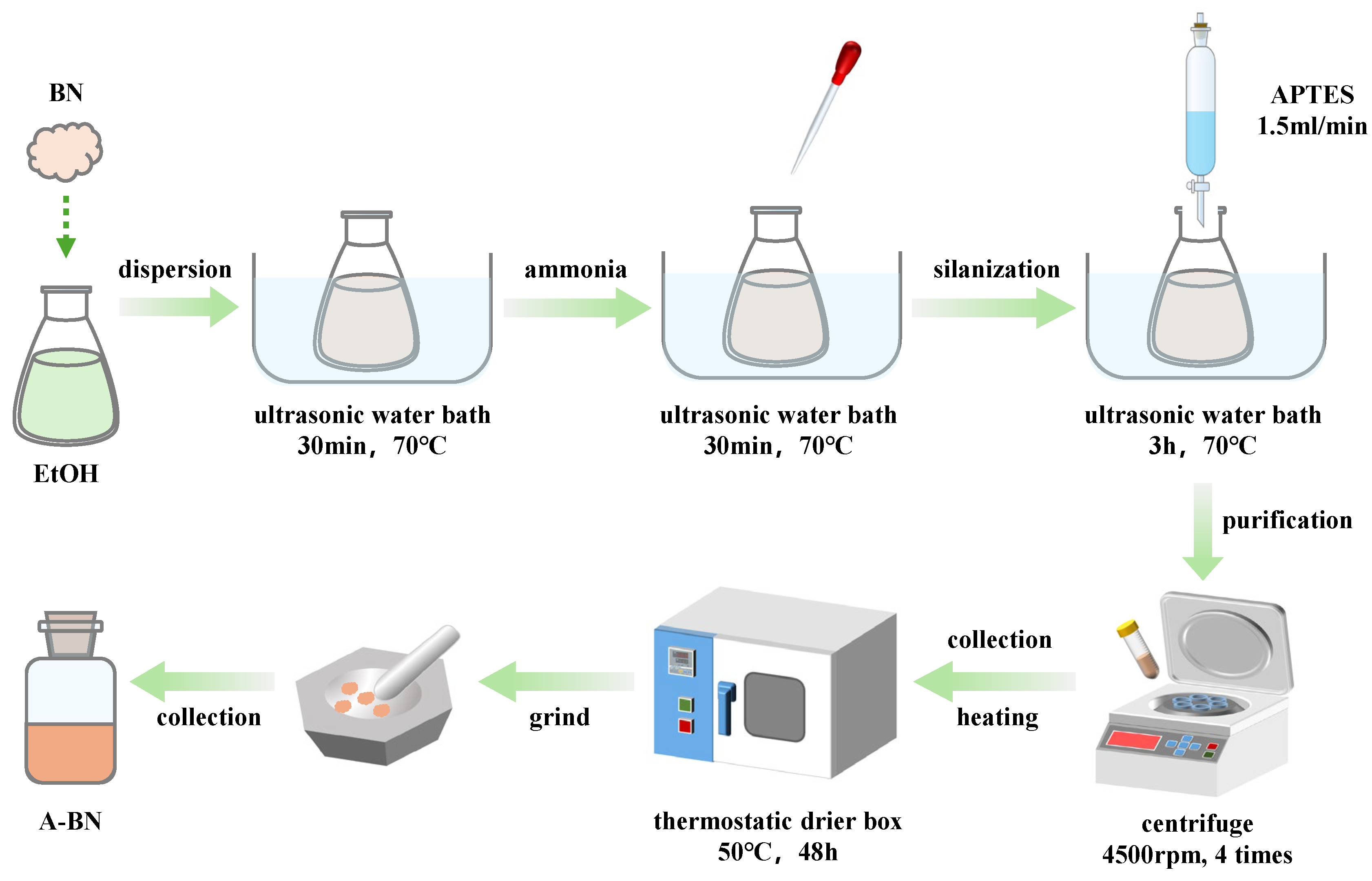
Figure 1. Schematic of synthesis procedure of A-BN.
Coatings 15 01281 g001
Figure 2. Schematic diagram of the preparation of coating.
Coatings 15 01281 g002
Figure 3. EIS results for IBE coatings. (a) Nyquist; (b) Bode-|Z|; (c) Bode-phase.
Coatings 15 01281 g003
Figure 4. EIS fitting results for the IBE coating. (a) Equivalent Circuit Diagram Model; (b) The fitted parameters of Rc and Rct for EPN, BE and IBE coatings; (c) The impedance modulus (Zf = 0.01 Hz) after soaking in synthetic seawater solution for 7 days at 60 °C.
Coatings 15 01281 g004
Figure 5. EIS results for GI5BE coatings. (a) Nyquist; (b) Bode-|Z|; (c) Bode-phase.
Coatings 15 01281 g005
Figure 6. EIS fitting results for the GI5BE coating. (a) The fitted parameters of Rc and Rct for I5BE and GI5BE coatings; (b) The impedance modulus (Zf = 0.01 Hz) after soaking in synthetic seawater solution for 7 days at 60 °C.
Coatings 15 01281 g006
Figure 7. EIS results for G2I5BE coatings. (a) Nyquist; (b) Bode-|Z|; (c) Bode-phase.
Coatings 15 01281 g007
Figure 8. EIS fitting results for the IBE coating. (a) The fitted parameters of Rc and Rct for G2I5BE coatings; (b) The impedance modulus (Zf = 0.01 Hz) after soaking in synthetic seawater solution for 28 days at 60 °C.
Coatings 15 01281 g008
Figure 9. Water absorption rate result of different coatings.
Coatings 15 01281 g009
Figure 10. Macroscopic morphology of the damaged coating area. (a) EPN; (b) BE; (c) I5BE; (d) G2I5BE.
Coatings 15 01281 g010
Figure 11. Micro-morphology of the metal substrate at the break of different coatings: (a1) EPN; (b1) BE; (c1) I5BE; (d1) G2I5BE; EDS results at the break of different coatings: (a2) EPN; (b2) BE; (c2) I5BE; (d2) G2I5BE.
Coatings 15 01281 g011aCoatings 15 01281 g011b
Figure 12. XPS deconvolution of the carbon steel surface where the EPN coating was broken: (a) XPS survey, (b) O 1s, (c) Fe 2p.
Coatings 15 01281 g012
Figure 13. XPS deconvolution of the carbon steel surface where the G2I5BE coating was broken: (a) XPS survey, (b) N 1s, (c) O 1s, (d) Fe 2p.
Coatings 15 01281 g013aCoatings 15 01281 g013b
Figure 14. Cross-sectional micro-morphology of different coatings: (a1) EPN; (b1) BE; (c1) I5BE; (d1) G2I5BE; EDS results at the break of different coatings: (a2) EPN; (b2) BE; (c2) I5BE; (d2) G2I5BE.
Coatings 15 01281 g014aCoatings 15 01281 g014b
Figure 15. EDS mapping of G2I5BE coating (a) overall situation, (b) B, (c) N, (d) C, (e) O, (f) Si.
Coatings 15 01281 g015
Figure 16. Schematic diagram of the mechanism of corrosion resistance and self-healing properties of GIBE coating.
Coatings 15 01281 g016
Figure 17. The chemical mechanism of chelation reactions between GA and Fe2+ and Fe3+ [29].
Coatings 15 01281 g017
Table 1. Basic details of the experimental materials and reagents.
No.NameSpecificationModelSupplier
1h-BNIndustrial-grade100 nmShanghai Mitsuda Nano New Material Co., Shanghai, China
2EPNIndustrial-gradeNPPN-630LShanghai Mitsuda Nano New Material Co., Shanghai, China
3solidify agentIndustrial-gradeAncamine 2280Shanghai Mitsuda Nano New Material Co., Shanghai, China
4GAIndustrial-grade99%Shanghai McLean Biochemical Technology Co., Shanghai, China
5IMIndustrial-gradeoil solubility, 98%Shanghai McLean Biochemical Technology Co., Shanghai, China
6APTESAR99%Shanghai McLean Biochemical Technology Co., Shanghai, China
7Et-OHAR99.9%Chengdu Kelong Chemical Co., Chengdu, China
8ammonia waterAR99.9%Chengdu Kelong Chemical Co., Chengdu, China
9ACAR99.9%Chengdu Kelong Chemical Co., Chengdu, China
10NaClAR99.99%Shanghai McLean Biochemical Technology Co., Shanghai, China
11MgCl2AR99.99%Shanghai McLean Biochemical Technology Co., Shanghai, China
12Na2SO4AR99%Shanghai McLean Biochemical Technology Co., Shanghai, China
13CaCl2AR99.99%Shanghai McLean Biochemical Technology Co., Shanghai, China
14KClAR99.5%Shanghai McLean Biochemical Technology Co., Shanghai, China
15NaHCO3AR99.5%Shanghai McLean Biochemical Technology Co., Shanghai, China
16KBrAR99%Shanghai McLean Biochemical Technology Co., Shanghai, China
17H3BO3AR99.5%Shanghai McLean Biochemical Technology Co., Shanghai, China
18SrCl2AR99.99%Shanghai McLean Biochemical Technology Co., Shanghai, China
19NaFAR99.99%Shanghai McLean Biochemical Technology Co., Shanghai, China
Table 2. IM content of different coatings.
CoatingsBEIBE
IM content (wt.%)00.5135
Table 3. GA content of different coatings.
CoatingsIBEGIBE
GA content (wt.%)00.5123
Disclaimer/Publisher’s Note: The statements, opinions and data contained in all publications are solely those of the individual author(s) and contributor(s) and not of MDPI and/or the editor(s). MDPI and/or the editor(s) disclaim responsibility for any injury to people or property resulting from any ideas, methods, instructions or products referred to in the content.