Abstract
The paper addresses tribocorrosion resistance studies of components made from the iron alloy Fe (0.21% C, 0.8% Si, 1.29% Mn, 1.34% Cr) using the Wire Arc Additive Manufacturing (WAAM) technology. The authors have developed their original heat treatment technology, where oil baths are used, leading to an increase in impact strength. This treatment combines processes such as austenitising, martensitic hardening, tempering, and austempering. As part of the research tests, tribocorrosion wear measurements were conducted in a 3.5% NaCl solution on both heat-treated and non-treated samples. The measurements showed lower tribocorrosion wear in the samples subjected to the novel heat treatment.
1. Introduction
The development of the additive manufacturing technology is becoming increasingly evident, especially across the methods based on material deposition using directed energy (Directed Energy Deposition, DED) [1,2,3,4,5]. Additive manufacturing is among the fastest-growing production techniques of this day and age. It consists of the layered application of material in powder or wire until the desired object shape is obtained. Such technologies are particularly widespread in the area of rapid prototyping of complex machine parts. They make it possible to create objects, including metal ones, in a cost-effective and flexible manner, without the need for specialized tools. Unlike traditional manufacturing methods, additive manufacturing techniques enable full process automation, from the design stage to final production, which significantly increases their efficiency.
Wire Arc Additive Manufacturing (WAAM) is a technology that employs an electric arc as an energy source to melt metal wire, which is subsequently deposited, layer by layer, to build three-dimensional objects [6,7,8,9,10,11,12]. The process uses standard welding wire, which makes it relatively inexpensive, and does not require significant logistics to obtain the resource. WAAM is classified among high-throughput additive processes, enabling fabrication of even large-sized parts [13,14,15,16,17,18,19].
Given the nature of the process, which involves significant amounts of energy being generated, the microstructure of the parts manufactured becomes heterogeneous, which typically leads to increased internal stresses and hardness.
Some of the characteristics of the microstructures obtained by way of additive manufacturing are as follows [20,21,22,23,24,25]:
- −
- Variable grain size within the material;
- −
- Directional grain orientation—usually vertical, and parallel to the material deposition direction.
The latter characteristic features the materials obtained by the WAAM method, which is attributed to the formation of a temperature gradient between successive layers over the course of heating, leading to preferential vertical grain growth. Consequently, the material microstructure becomes anisotropic, and its mechanical properties, such as strength, vary depending on the said direction. One of the effective ways to improve the structure and mechanical properties of materials is heat treatment, which follows the additive manufacturing process. As mentioned in paper [26], heat treatment can successfully decrease residual stresses, thus reducing the risk of workpiece deformation over time. The studies described in papers [27,28] confirm that heat treatment has a beneficial effect on the plastic properties of components manufactured using this technology. Gunen et al. [29] also observed that processes such as homogenising and boriding can significantly reduce the wear and friction coefficient of stainless steel components produced by WAAM.
The authors of paper [30] also demonstrated that the WAAM method can be applied to produce materials of favourable mechanical properties, and particularly to improve their impact strength, by way of dedicated multi-stage heat treatment using a fluidised bed furnace for isothermal procedures. The treatments they discussed also yielded almost complete defragmentation of columnar grains which, however, caused a decrease in surface hardness.
The favourable changes observed in connection with the technology developed, combining austenitisation, martensitic quenching in mineral oil, annealing, and austempering in a fluidised bed, provided foundations for the continuation of research on the heat treatment processes adapted to the specific characteristics of materials produced by additive manufacturing, which, however, will use industrial furnaces based on oil coolants. The outcome of the research in question was the development of the heat treatment technology described in this paper.
Considering the potential practical application of the technology in question, namely in the production of individual workpieces required for the repair of machinery operating in severe environmental conditions, it was decided that, once manufactured and treated, the workpieces would be subjected to tribocorrosion wear processes in order to demonstrate their resistance to the combined effects of environmental factors such as abrasive wear and corrosion. The foregoing was due to the fact that friction nodes in machines often operate in electrolytic and abrasive environments [31,32]. The problem of tribocorrosion wear of the iron alloys produced by additive manufacturing methods has been virtually undiagnosed [33,34].
In recent years, several studies have been published on the tribocorrosion of iron alloys produced by additive manufacturing. In their work, Wieczorek et al. [35] examined an iron alloy corresponding to C300 maraging steel produced by additive manufacturing using different laser powers. The authors evaluated hardness, abrasion resistance, corrosion resistance, and tribocorrosion resistance in a 3.5% NaCl solution. Their results showed that lower laser power promoted the formation of a finer microstructure and higher hardness, which improved mechanical wear resistance. However, the fine-grained structure simultaneously worsened corrosion resistance. Tribocorrosion tests revealed that increased hardness does not always translate into lower wear in a corrosive environment; there is a clear trade-off between abrasion resistance and corrosion resistance.
Similar conclusions were reported in [36]. The authors found that iron alloys produced by WAAM exhibit overall corrosion resistance comparable to traditional steels of the same composition and structure, but they are more susceptible to localized corrosion due to the presence of silicon- and manganese-rich inclusions. These phenomena promote microcracks and local galvanic cells, potentially increasing the risk of degradation under combined friction and corrosion conditions.
A review by Marques et al. [37] discusses the general corrosion behavior of WAAM-produced materials, including iron alloys. The authors point out that the corrosion properties of additively manufactured steels strongly depend on process parameters, porosity, residual stresses, and surface condition. In many cases, WAAM materials exhibit poorer corrosion resistance than their conventional counterparts, but appropriate heat and surface treatments can significantly improve these properties. The lack of comprehensive studies combining abrasion and corrosion, i.e., tribocorrosion, in relation to WAAM-produced steels has also been noted.
In summary, the literature indicates that the tribocorrosion behavior of iron alloys largely depends on microstructure and manufacturing parameters. Fine-grained structures improve mechanical resistance but may increase susceptibility to corrosion. There remains a lack of comprehensive studies on WAAM steels under simultaneous abrasion and corrosion conditions, representing a significant research gap and a potential direction for future work.
It is also noteworthy that yet another particularly important and difficult problem is obtaining a microstructure of structural materials that ensures sufficiently high resistance to tribocorrosion. The material must be characterised by high abrasion hardness, while being immune to the corrosive effects of the operating environment, at the same time. To produce such a complex set of material properties (e.g., by way of adequate heat treatment) is a complicated endeavour. It is so because treatments that increase material hardness typically reduce its resistance to corrosion (e.g., hardening increases hardness and abrasion resistance, but the stresses introduced into the material increase its susceptibility to corrosion).
The aim of the study presented in this article was to determine the effect of a new heat treatment method on WAAM-fabricated materials on the tribocorrosion process in a 3.5% NaCl solution, compared to materials not subjected to heat treatment.
What the article provides is an analysis of the relationship between the properties of the material developed by the manufacturing technology in question (including dedicated heat treatment) and the elementary mechanisms causing wear, especially under the conditions of tribocorrosion. With this goal in mind, the authors compared the results of wear tests of heat-treated samples with those of base reference (non-treated) samples. The analysis of the test results implied a probable mechanism of the effect of increased material impact strength (being the heat treatment effect) on the reduction in tribocorrosion wear.
It should be emphasized that the newly developed manufacturing technology presented in this study has significantly increased the impact toughness of the investigated material, enabling its application in components subjected to dynamic loading. In the current state of the art, there are no reported processes based on isothermal treatments that achieve a comparable improvement in mechanical properties to that obtained with the proposed method. Furthermore, the available scientific literature lacks studies on the tribo-corrosion properties of steels produced using the Wire Arc Additive Manufacturing (WAAM) technique. These factors highlight the innovative nature of the research topic presented in this article.
2. Materials and Methods
2.1. Material
As part of the rapid prototyping experiment, a ferrous alloy produced using a flux-cored wire of 1.6 mm in diameter was used. The exact chemical composition of the said wire and the MAG process parameters have been provided in Table 1 and Table 2, respectively. This kind of wire is commonly used for hard facing, and its typical applications include regeneration of rolling wheels, conveyor rollers, rolls, shafts, and other machine components.

Table 1.
Chemical composition of the material subject to tests [30].
Table 2.
Parameters of the WAMM prototyping process [30].
The choice of this particular material for testing was based on the results obtained by computer simulations in the JMatPro, version 12.2, (Sente Software Ltd., Guildford, UK), dilatometric tests, as well as previous studies [30], which had confirmed its high heat treatability.
Before the process commenced, the base surface had been thoroughly cleaned mechanically and degreased to ensure optimal adhesion conditions. No additional cooling was used over the course of the entire process.
The experimental rapid prototyping process was conducted on a 20 mm thick plate made of the S690QL1 steel. A structure composed of seven layers was produced, each of which consisted of eight seams.
The heat treatment process developed by the authors consisted of four major stages:
- −
- Austenitising, during which the material was heated to 950 °C and held at this temperature for 25 min;
- −
- Martensitic quenching in polymer coolant, directly following austenitisation;
- −
- Annealing, conducted at 760 °C for 60 min;
- −
- Isothermal transformation hardening was carried out at 260 °C for 180 min in the high-temperature quenching oil Marquench 3500 from Petrofer, Hildesheim, Germany. The average cooling rate of this bath, measured using a thermocouple embedded in a 10 × 10 mm steel specimen, was approximately 25 °C/s in the temperature range from 800 °C to 500 °C.
2.2. Mechanical Tests
The samples used for testing of mechanical properties and tribocorrosion wear were cut out from the material produced by the WAAM method. To ensure uniform conditions, all the samples were taken parallel to the deposition layers, at a minimum distance of 5 mm from the die surface. Thus prepared, the samples were divided into two groups: one representing the reference material, while the second group was heat-treated in a manner adapted to the chemical composition of the material.
A series of tests was performed to assess the mechanical properties of the material before and after the heat treatment.
- Static tensile testing—the static tensile tests were performed on a Zwick/Roell Z250 universal testing machine (ZwickRoell GmbH & Co. KG, Ulm, Germany). The tests were conducted in accordance with PN-EN ISO 6892-1:2010 [38] at room temperature. Five time samples with a measuring diameter of 6 mm were used, applying a constant strain rate of 0.001 s−1.
- Impact testing—the impact test was performed on standardised samples of 55 × 10 × 10 mm in dimensions with a V notch in accordance with PN-EN ISO 148-1:2010 [39]. A Zwick/Roell RKP450 Charpy impact hammer with a nominal energy of 300 J was used for the measurements.
- Hardness testing—the hardness measurements were performed on the flat surfaces of samples cut out in a manner analogous to the samples used for strength and impact testing. A stationary HR-150 Rockwell Hardness Tester (Shandong Shancai Testing Instrument Co., Ltd., Jinan, China) was used to determine this parameter.
2.3. Microstructural and Phase Characteristics
A SUPRA 35 type high-resolution scanning electron microscope (SEM) from Zeiss, Jena, Germany was used to identify the microstructure and the surface wear mechanism of the materials tested, both before and after heat treatment. The observations were conducted by secondary electron (SE) detection. The phase composition was analysed using an X’Pert PRO MPD X-ray diffractometer (XRD) from Panalytical, Malvern, UK. The device was fitted with a cobalt anode lamp (λKα = 0.179 nm) and a PIXcel 3D detector. The Bragg–Brentano geometry measurements were performed within the 2θ angle range from 5° to 110° with a 0.05° step and a counting time of 100 s per step. The diffractograms were subject to a qualitative phase analysis performed using the HighSore Plus software (v. 3.0e) and the dedicated PAN-ICSD database.
2.4. Tribological Tests
A test rig based on a ball-on-plate model system [30,34] was used to assess wear resistance. Figure 1 shows a diagram of the test stand and the ball-on-plate node. The following samples were used in the tests:
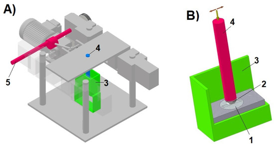
Figure 1.
Test stand: (A)—general view, (B)—ball-on-plate node, (1—sample, 2—ball, 3—chamber with corrosive environment, 4—pin with ball holder and load, 5—eccentric drive).
- −
- Cube-shaped samples with 10 mm edges;
- −
- Counter-samples (balls) made of Al2O3 with a diameter of 7.0 mm.
The tested samples were standard impact test specimens with a cross-section of 10 × 10 mm and 5 mm thick tribological test discs cut from larger elements with dimensions 150 × 75 × 75 mm. All the tests were performed with a load of 10 N and a sliding speed of approx. 18 mm/s. Under each test, the ball, driven by an eccentric mechanism, slid back and forth across the sample surface over a distance of 6 mm for approx. 40 min. The total friction distance was 43.2 m. Each test was repeated three times.
After the wear tests were completed, profilometric measurements of the wear marks were taken. Based on these measurements, the volumetric material loss was estimated. For purposes of further analysis, it was assumed that volumetric wear would be a measure of the material’s resistance to tribocorrosion and mechanical wear only.
The research experiment was designed to identify the individual components of tribocorrosion wear (ZT) in line with the following relationship:
where ZM—material loss caused exclusively by mechanical interactions, ZC—material loss caused exclusively by corrosive interactions, ΔZ—synergistic effect of friction and corrosion.
The total tribocorrosion wear (ZT) was determined in 3.5% NaCl at the free corrosion potential. In a series of additional independent experiments conducted under cathodic polarisation conditions, the purely mechanical component (ZM) was determined. The polarisation potential applied (approx. −900 mV (SCE)) eliminated corrosive effects in 3.5% NaCl. The component (ZC) corresponding to the purely corrosive wear was estimated using Faraday’s equation. The relevant calculations were performed for the specific corrosion current density and test duration time. The measure of the combined effect of friction and corrosion is the ΔZ factor, which can be determined by transforming Equation (1).
During the tribocorrosion tests, the potential was measured in the test system with the sample using a potentiostat from ATLAS Sollich, Rębiechowo, Poland. A calomel electrode was used as the reference electrode, while a platinum mesh was used as the auxiliary electrode. The potentiostat was also used to determine polarisation curves and to assess the corrosion resistance of the materials studied.
3. Results
3.1. Microstructure and Mechanical Properties
Figure 2 shows the initial microstructure of the material obtained by the WAAM method (Variant A), while Figure 3 shows it after the heat treatment (Variant B).
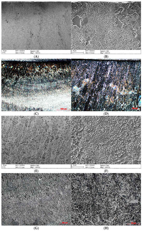
Figure 2.
Microstructures obtained for Variant A. (A)—found in the near-surface area of the cross-section, SEM, ×1000; (B)—found in the near-surface area of the cross-section, SEM, ×5000; (C)—found in the near-surface area of the cross-section, LM, ×25; (D)—found in the near-surface area of the cross-section, LM, ×100; (E)—found in the core, SEM, ×1000; (F)—found in the core, SEM, ×5000; (G)—found in the core, LM, ×100; (H)—found in the core, LM, ×500.
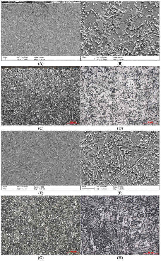
Figure 3.
Microstructures obtained for Variant B. (A)—found in the near-surface area of the cross-section, SEM, ×1000; (B)—found in the near-surface area of the cross-section, SEM, ×5000; (C)—found in the near-surface area of the cross-section, LM, ×25; (D)—found in the near-surface area of the cross-section, LM, ×100; (E)—found in the core, SEM, ×1000; (F)—found in the core, SEM, ×5000; (G)—found in the core, LM, ×100; (H)—found in the core, LM, ×500.
The phase composition of the microstructure in the near-surface area of the sample under Variant A is significantly diversified. There are heat-affected zones (Figure 2A–D) where the grains display different shapes. The area directly underlying the surface, to the depth of approx. 1 mm, is dominated by darker columnar grains. They are oriented perpendicularly to the layer applied and comprise a mixture of bainite and martensite, separated by thin layers of ferrite. Some of these elongated grains are in direct contact with the surface.
What continues to be observed in the material core (Figure 2E,G), at a magnification of ×100, is the partially directional nature of the structure with a predominance of bainite, but analysis of individual areas shows no explicit grain orientation (Figure 2F,H).
In the case of Variant B (Figure 3A–D), no columnar grains or other forms of directionally oriented phase are observed in the surface layer. The resulting ferritic-bainitic structure, perceived as a homogeneous phase, shows no organised arrangement, with grains distributed randomly and multidirectionally.
The middle part’s microstructure (Figure 3E,G) in the heat-treated sample (Variant B) comprises ferrite (light phase), which did not transform during incomplete austenitisation, and bainite, which was formed as an outcome of the transition of austenite over the course of isothermal soaking. This structure is far more ordered than that obtained for Variant A. One can observe an explicitly layered arrangement of bainite plates separated by ferrite (Figure 3F,H).
A comparison of Figure 2H with Figure 3H clearly shows that the innovative heat treatment led to considerable fragmentation of the originally elongated grains. This process demonstrates the beneficial effect of the method developed by the authors on the microstructure of the material produced by the WAAM technique.
However, it should be noted that the original heat treatment procedure in question did not lead to phase transformations, as confirmed by the results of the XRD phase composition tests of the materials tested, shown in Figure 4. The peaks visible in this figure are associated exclusively with the alpha iron, which confirms the occurrence of ferritic and bainitic phases.
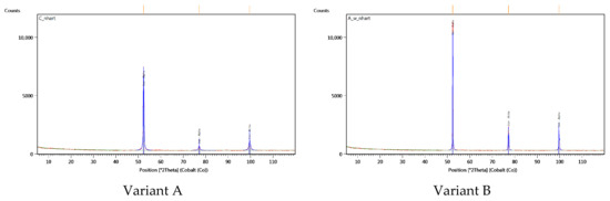
Figure 4.
Diffractograms of the materials examined.
The obtained diffraction data (Table 3) reveal differences in the intensity and broadening of the recorded peaks originating from the alpha iron phase. It can be assumed that the lower peak intensity and greater full width at half maximum (FWHM) observed in the diffractogram for Variant A may result from reduced grain size and/or accumulation of crystal lattice defects (substructure).
Table 3.
Peak parameters derived from X-ray diffractograms.
3.2. Tests of Mechanical Properties
Table 4 contains the results of the tests of the mechanical properties of the iron alloy Fe (0.21% C, 0.8% Si, 1.29% Mn, 1.34% Cr). They were conducted to compare the material in the as-produced (Variant A) and heat-treated (Variant B) conditions.
Table 4.
Mechanical properties of the material examined, in as-produced and heat-treated condition.
The heat treatment caused significant changes in the alloy’s most important properties:
- −
- Hardness reduced by approx. 7 HRC, which could be interpreted as a direct result of the increased ferrite share in the near-surface layer following the heat treatment,
- −
- Yield strength decreased by approx. 25%,
- −
- Maximum strength decreased by approx. 15%,
- −
- Impact strength increased by 43 J/cm2, which represents an impressive increase of 238% compared to the reference material (Variant A).
3.3. Corrosion Resistance
The corrosion resistance of the materials studied in 3.5% NaCl was assessed on the basis of polarisation curves. The characteristics determined for both the material variants subject to tests have been presented in Figure 5. Based on the polarisation curves plotted for them, their corrosion potential (Ecorr) and corrosion current density (icorr) were established using the Tafel method. The results thus obtained have been provided in Table 5. For the base material (Variant A), the corrosion potential was −699 mV (SCE) and the corrosion current density was 17.3 µA/cm2. For the heat-treated material (Variant B), the corrosion potential was −633 mV (SCE) and the corrosion current density was 9.2 µA/cm2. A higher corrosion potential and lower corrosion current density imply higher corrosion resistance in 3.5% NaCl of the heat-treated material (Variant B) lower corrosion current density implies higher corrosion resistance in 3.5% NaCl of the heat-treated material (Variant B).
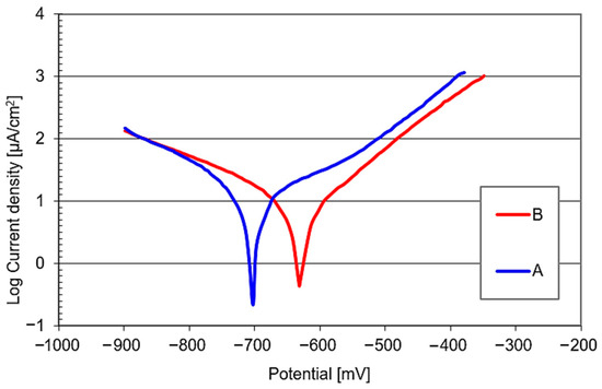
Figure 5.
Polarisation curves of the materials examined (3.5% NaCl).
Table 5.
Corrosion potential (Ecorr) and corrosion current density (icorr) of the materials examined.
3.4. Tribocorrosion Results
Table 5 contains the values of the material loss following tribocorrosion tests and that observed under purely mechanical wear conditions (with cathodic polarisation). The data include the average values obtained in a series of measurements and the standard deviation.
Additionally, the component of the friction and corrosion synergy effect (ΔZ) was estimated. Analysis of the data provided in Table 6 implies that the samples subjected to the specialised heat treatment procedure (Variant B) show less wear under tribocorrosion conditions in a 3.5% NaCl solution. The average material loss in these samples was approximately 2.59 × 10⁻³ mm3. In the base samples (Variant A), the material loss was greater and amounted to approx. 3.59 × 10⁻³ mm3. Lower wear values were also recorded under purely mechanical conditions when studying Variant B (1.75 × 10⁻³ mm3) in comparison with Variant A (2.49 × 10⁻³ mm3). For both these material variants subject to testing under tribocorrosion conditions, a clear synergy effect of friction and corrosion was observed, representing more than 30% of the total material loss.
Table 6.
Results of the tests of wear processes.
The wear mark profiles established in the studies have been provided in Figure 6.
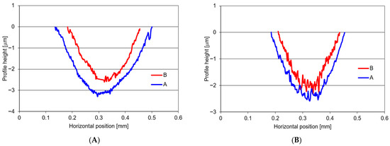
Figure 6.
Wear profiles established for: (A)—tribocorrosion wear (ZT), (B)—mechanical wear only (ZM).
Over the course of the wear tests, changes in the electrochemical potential of the system were monitored, as shown in Figure 7. The graphs demonstrate that both the material variants examined are not capable of passivation in a 3.5% NaCl solution. Having immersed the sample in the NaCl solution, without any friction, one could observe an initial potential decrease. This is attributable to the formation of a thin layer of corrosion products on the material surface. When friction begins (counter-sample movement), this corrosion layer is removed. The wear area acquires a more positive potential than the remainder of the sample surface, causing a noticeable potential increase. On the other hand, when the friction force is stopped, the potential decreases again.
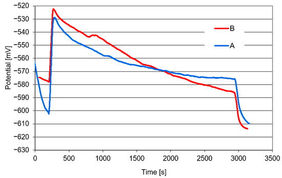
Figure 7.
Changes in the potential of the material variants examined under tribocorrosion test conditions.
After the tests had been completed, the hardness in the wear mark area was measured. No considerable material consolidation was observed, as the hardness measured inside the wear mark did not diverge significantly from the material hardness outside this area.
3.5. Worn Surface Damage
Once the tests had been completed, microscopic observations of the wear surface were conducted. Figure 8 shows examples of the wear marks observed in the base samples (Variant A) obtained under tribocorrosion and purely mechanical wear conditions. The corresponding marks found in the heat-treated samples (Variant B) are shown in Figure 9.
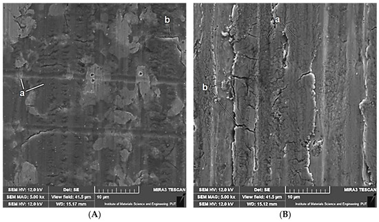
Figure 8.
Wear marks on the surface of non-heat-treated samples (Variant A) following tests under tribocorrosion conditions (A) and under mechanical wear conditions (B). Designations: a—grooves; b—cracks.
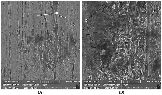
Figure 9.
Wear marks on the surface of heat-treated samples (Variant B) following tests under tribocorrosion conditions (A) and mechanical wear conditions (B). Designations: a—grooves; b—cracks.
The photographs depicting the wear marks indicate that the predominant mechanism of material removal is abrasion. There are numerous parallel grooves visible on the surface of most samples, resulting from the micro-abrasion of the sample material by harder coarse protrusions of the moving counter-sample (balls). These grooves are particularly visible on the wear marks observed under the conditions of purely mechanical forcing and in the reference base material (Variant A). The heat-treated material (Variant B) is characterised by lower hardness, which makes it more susceptible to plastic strain. Under such conditions, grooving is more likely to occur than micro-abrasion. On the other hand, under the conditions of tribocorrosion, corrosion processes may cause partial removal of microabrasion marks (grooves being shallower and less numerous). What can also be seen on the surface of the wear marks are microcracks, especially with mechanical forcing at play.
4. Discussion
The authors developed a new heat treatment technology for the investigated ferrous alloy. Its purpose was to eliminate grain anisotropy and to obtain a multiphase micro-structure with improved plasticity and impact toughness. This procedure is based, among other factors, on microstructure fragmentation. The heat treatment process was designed on the basis of the computer simulations performed in the JMatPro software as well as the aforementioned dilatometric tests, which made it possible to define the parameters of consecutive treatments and their optimal combination.
The heat treatment proposed in this study is inspired by TAM-type processes (TRIP-aided annealed martensitic steels), as described by K. I. Sugimoto et al. [40,41]. In their approach, martensitic quenching was employed as a preliminary thermal treatment prior to bainitic transformation following intercritical annealing. This strategy was used to tailor the properties and microstructure of steels with chemical compositions similar to those investigated in the present work. Their primary objective was to enhance fatigue strength. Gołaszewski et al. [42] also highlight the benefits of implementing a preliminary quenching step prior to intercritical annealing, employing bainitic quenching following full austenitization. This approach contributes to the refinement of microstructure and enhancement of mechanical properties, aligning with strategies aimed at optimizing the performance of advanced steels.
During slow heating at a rate of 2 °C/min, the intercritical range was determined between the temperatures of the start (A1 = 750 °C) and finish (A3 = 880 °C) of the austenitic transformation (Figure 10). This analysis facilitated the selection of both the full austenitisation temperature and the intercritical annealing temperature. In the present case, the temperature of full austenitisation was chosen to be relatively high (950 °C) to ensure optimal homogenisation of the WAAM-produced material. For the TAM-type treatment, the intercritical annealing temperature was selected to reduce the Ms temperature (760 °C). In steels with increased silicon content, such as the one investigated in this study, it is possible to obtain carbide-free bainite containing stabilised retained austenite exhibiting the TRIP effect. According to the literature, such a microstructure is characterised not only by good ductility but also by enhanced wear resistance. The application of partial austenitisation increases the carbon concentration in austenite, thereby lowering its martensite start temperature (Ms) from 390 °C (austenitisation at 950 °C) to approximately 255 °C (intercritical annealing at 760 °C). The Ms temperature after intercritical annealing was identified on the cooling curve (Figure 11). The lower Ms temperature enabled bainitic transformation at a temperature favourable for significant microstructural refinement (260 °C was applied). Ultimately, a bainitic structure with retained austenite in a ferritic matrix was obtained.
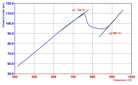
Figure 10.
Dilatometric graphs of the material produced by WAAM after slow heating was applied to determine the temperatures A1 and A3.
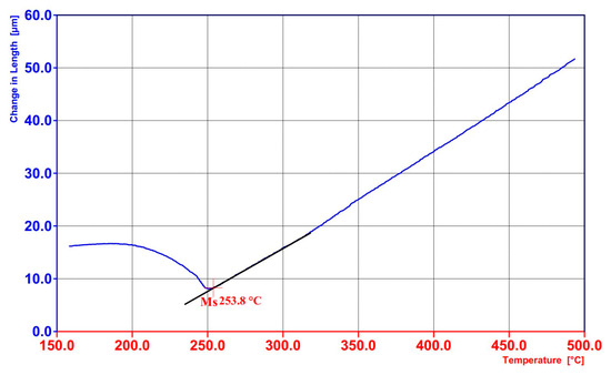
Figure 11.
Dilatometric graphs of the material produced by WAAM after annealing at 760 °C with visible Ms temperature of 255 °C.
The heat treatment proposed by the authors made it possible to cause favourable changes in the microstructure. In the core zone of the samples, a bainite structure embedded in a ferritic matrix was formed (Figure 3A–D), while in the near-surface zone, significant fragmentation of columnar grain was observed (Figure 3E–H). These structural modifications translated into significant improvement in the material properties. Variant B, compared to the base material (Variant A), exhibits better plasticity, facilitating plastic deformation. Despite the reduction in hardness by approx. 30% and in yield strength by approx. 25%, the main benefit is a more than threefold increase in impact strength, as confirmed by the data in Table 3.
The test results provided (Figure 6, Table 5) prove that the heat treatment proposed by the authors improves the wear resistance of the material examined. Compared to the base samples (Variant A), the samples subjected to the innovative heat treatment (Variant B) showed less volume loss following wear tests, both under tribocorrosion and purely mechanical wear conditions.
The base material (Variant A) analyzed in this article was produced by the WAAM method. Microstructural observations did not reveal any defects (porosity). Furthermore, the presented test results (Table 5, Figure 6) indicate that the proposed heat treatment significantly improves corrosion resistance in 3.5% NaCl. The post-treatment material (Variant B) exhibited a higher corrosion potential and lower corrosion current density.
The corrosion properties of the material produced using the WAAM method are closely related to its microstructure, which is a direct result of the applied technological process, including cladding parameters, cooling rate, and possible heat treatment. The nature of the microstructure determines local differences in electrochemical potentials between phases, which directly affect the mechanisms of corrosion initiation and propagation. In the case of Variant A, obtained exclusively by welding-based methods, an anisotropic structure was formed, consisting of a mixture of bainite and martensite separated by thin ferrite layers. The presence of martensite, characterized by high hardness and internal stresses, may additionally promote the formation of microcracks that serve as preferential sites for corrosion processes. Variant B, produced as a result of an innovative heat treatment applied to the WAAM material, exhibits a more homogeneous and fine-grained ferritic–bainitic structure. The reduction in the martensitic phase, together with a decrease in chemical composition gradients and internal stresses, results in a significant reduction in corrosion activity. The superior corrosion resistance of Variant B compared to Variant A can therefore be attributed both to the absence of martensite in the microstructure and to a more favorable distribution of phases with similar electrochemical potentials. Due to its high free energy and structural defects, the martensitic phase is more susceptible to corrosion than bainite or ferrite. This relationship was confirmed by Guerra-Linares et al. [43], based on measurements of corrosion potential (Ecorr) and corrosion current density (icorr) of steels subjected to different heat treatment variants. Similar conclusions were also reported by Ku et al. [44].
The relationship observed in the material variants examined is not obvious because the material of a significantly lower (by 30%) hardness shows less wear. However, thanks to the dedicated heat treatment, the impact strength of this material (Variant B) is more than three times higher. In order to explain the effect of the higher impact strength of the material (on lower hardness) on the wear reduction, the authors have applied the energy model of the wear process proposed by G. Fleischer [45,46].
The concept concerns a friction node where two bodies come into contact under load. Friction energy is generated as a result of the frictional interactions associated with the mutual displacement of these bodies. This energy is absorbed by the more susceptible element of the friction couple. According to the model, each body can accumulate a certain amount of this energy in the near-surface layer. Once the critical energy threshold is exceeded, the deformed volume of the near-surface layer breaks off, thus forming a new wear particle. The detachment of the deformed micro-volume can be attributed to the development of micro-cracking.
What G. Fleischer’s energetic wear model takes into account is the elementary mechanisms of material removal identified on the surface of the wear marks in the samples subject to tests. The wear marks visible in Figure 8 and Figure 9 imply that the frictional contact with the hard surface of the counter-sample causes plastic strain of the near-surface layer of the sample material. Such a strain can lead to the immediate breaking off of the deformed micro-volume of the material as a result of micro-abrasion (especially in the case of the base material (Variant A), characterised by higher hardness and lower impact strength). The strain can also cause grooving without immediate material detachment. However, in the area of the locally deformed near-surface layer, micro-cracking may be initiated. When repeated on a cyclical basis, frictional effects promote the development of micro-cracks until the wear particle breaks off. Micro-cracks are visible on the surface of the wear marks (Figure 8 and Figure 9). In line with the energetic interpretation of the wear process, it can be assumed that the impact strength of the material (KCV) may be a factor that determines the value of the critical energy required for the wear particle to break off as a consequence of cracking. Previously released papers [47,48] describe studies that have demonstrated experimentally that the value of abrasive wear in sliding couples correlates more strongly with the impact strength of the material examined than with its hardness.
With reference to the energetic concept of the wear process, the authors of this paper have adopted a simplifying assumption that the aforementioned critical energy (required for the wear particle to break off) is proportional to the product of the material’s impact strength (KCV) and area A within which the material detachment occurs. The aforementioned area A can be approximated as the actual area of frictional contact between the sample and counter-sample AR. In the case of plastic strain, the real area of contact of the friction couple depends on the force affecting the friction node (F) and the material hardness (H):
In the heat-treated samples (Variant B), the threshold energy required for the wear particle to break off is higher than in the non-treated samples (Variant A). This conclusion is illustrated by the following inequalities:
ARA × KCVA < ARB × KCVB
ARA < ARB
KCVA < KCVB
The heat-treated material (Variant B) is characterised by higher impact strength (Table 3) and, most likely, a larger real contact area. However, the hardness of this material (Table 3) is lower. Consequently, the real contact between the sample and the counter-sample occurs over a larger area.
Ultimately, the heat-treated samples (Variant B) show a higher critical energy required for the wear particle to detach. It is due to this fact that more energy must be supplied to the friction node in order to remove the deformed near-surface layer of the material. To achieve this effect by way of wear, more contact interactions are necessary. The wear particle breaks off after a longer time than in the case of non-treated samples (Variant A). The relationship between impact strength and the elementary mechanisms of material removal, as described above, may explain the lower wear (especially under mechanical forcing conditions) of the heat-treated samples.
5. Conclusions
The main conclusions arising from the studies and analyses discussed in the article are as follows:
- It has been confirmed that it is possible to produce workpieces of high plastic properties from Fe (0.21% C, 0.8% Si, 1.29% Mn, 1.34% Cr) alloys by way of additive welding methods and advanced heat treatment. Microscopic observations and phase tests have shown that the heat treatment proposed by the authors, being a combination of austenitising, martensitic quenching, annealing, and austempering, enables comminution of the columnar grain in the ferrous alloy produced by WAAM.
- The heat-treated material (Variant B) shows significantly lower tribocorrosion and mechanical wear. It is also characterised by higher wear resistance, even though the dedicated heat treatment has caused its hardness to drop (by approx. 30%).
- In line with the description of the interactions in the friction node examined, as proposed by the authors of the article, the wear resistance of the analysed ferrous alloy improves as a consequence of increased impact strength. The heat-treated material (Variant B), offering lower hardness, is more susceptible to plastic strain during frictional interactions. However, the detachment of deformed micro-areas of the near-surface layer occurs after a longer time than in the base material (Variant A). The main reason for this phenomenon may be the higher critical energy required for the wear particles to break off. The value of the said critical energy is determined by the increase in the impact strength of the heat-treated material (Variant B), being more than threefold.
- The heat treatment proposed in the article improves the corrosion resistance of the material subject of the studies in 3.5% NaCl. In the heat-treated samples (Variant B), the corrosion current density was found to be approximately 40% lower. Consequently, this also causes less material loss due to corrosion processes occurring on the sample surface, in the areas exposed to friction under tribocorrosion conditions (these processes being the main cause of the friction-corrosion synergy effect).
- The advanced heat treatment proposed in the article is an example of a technological procedure that makes it possible to achieve a specific combination of material properties (increased resistance to abrasion and the corrosive effects of 3.5% NaCl) that is particularly favourable in terms of tribocorrosion resistance.
Author Contributions
Conceptualization, A.N.W.; methodology; A.N.W., validation, M.S.W. and P.N.; formal analysis, A.G. and S.M.; investigation, A.S. and P.N. and A.G. and S.M. and M.S.; resources, M.S.W. and S.M.; data curation, A.N.W.; writing—original draft preparation, A.S. and A.N.W., writing—review and editing, M.S.W.; visualization, P.N. and M.S.; supervision, A.N.W. and M.S.W. All authors have read and agreed to the published version of the manuscript.
Funding
The presented research results were conducted within the framework of completed projects: 1. The Silesian University of Technology, Excellence Initiative—Research University program implemented at the Silesian University of Technology, the year 2020, project No. 06/020/SDU/10-21-01 entitled. ‘Development of an innovative method for improving the functional properties of manufactured components by electron beam rapid prototyping’. 2. Łukasiewicz—Upper Silesian Institute of Technology, Development Fund project No. BW-30/ZB.
Institutional Review Board Statement
Not applicable.
Informed Consent Statement
Not applicable.
Data Availability Statement
The datasets presented in this article are not available as further analysis is currently underway for publication.
Conflicts of Interest
Author Marek S. Węglowski was employed by the company Ennecor Ltd. The remaining authors declare that the research was conducted in the absence of any commercial or financial relationships that could be construed as a potential conflict of interest.
References
- Blakey-Milner, B.; Gradl, P.; Snedden, G. Metal Additive Manufacturing in Aerospace: A Review. Mater. Des. 2021, 209, 110008. [Google Scholar] [CrossRef]
- Bandyopadhyay, A.; Heer, B. Additive Manufacturing of Multi-Material Structures. Mater. Sci. Eng. R Rep. 2018, 129, 1–16. [Google Scholar]
- Sommer, D.; Götzendorfer, B.; Esen, C.; Hellmann, R. Design Rules for Hybrid Additive Manufacturing Combining Selective Laser Melting and Micromilling. Materials 2021, 14, 5753. [Google Scholar] [CrossRef]
- Thompson, M.K.; Moroni, G.; Vaneker, T.; Fadel, G.; Campbell, I.; Gibson, I.; Bernard, A.; Schulz, J.; Graf, P.; Ahuja, B. Design for Additive Manufacturing: Trends, Opportunities, Considerations, and Constraints. CIRP Ann. 2016, 65, 737–760. [Google Scholar] [CrossRef]
- Derekar, K.S. A Review of Wire Arc Additive Manufacturing and Advances in Wire Arc Additive Manufacturing of Aluminium. Mater. Sci. Technol. 2018, 34, 895–916. [Google Scholar] [CrossRef]
- Li, J.L.Z.; Alkahari, M.R.; Rosli, N.A.B.; Hasan, R.; Sudin, M.N.; Ramli, F.R. Review of Wire Arc Additive Manufacturing for 3D Metal Printing. Int. J. Autom. Technol. 2019, 13, 346–353. [Google Scholar] [CrossRef]
- Rodríguez-González, P.; Ruiz-Navas, E.M.; Gordo, E. Wire Arc Additive Manufacturing (WAAM) for Aluminum-Lithium Alloys: A Review. Materials 2023, 16, 1375. [Google Scholar] [CrossRef]
- Harshita, P.; Anisha, A.; Sutha, G.G. Applications of Wire Arc Additive Manufacturing (WAAM) for Aerospace Component Manufacturing. Int. J. Adv. Manuf. Technol. 2023, 127, 4995–5011. [Google Scholar] [CrossRef]
- Iván-Tabernero, P.; Pascual, A.; Álvarez, P. Study on Arc Welding Processes for High Deposition Rate Additive Manufacturing. Procedia CIRP 2018, 68, 358–362. [Google Scholar] [CrossRef]
- Rodrigues, T.A.; Duarte, V.; Miranda, R.M.; Santos, T.G.; Oliveira, J.P. Current Status and Perspectives on Wire and Arc Additive Manufacturing (WAAM). Materials 2019, 12, 1121. [Google Scholar] [CrossRef]
- Yan, L. Wire and Arc Additive Manufacture (WAAM) Reusable Tooling Investigation. Ph.D. Thesis, Cranfield University, Bedford, UK, 2012. [Google Scholar]
- Martina, F.; Williams, S.W. Wire+Arc Additive Manufacturing vs. Traditional Machining from Solid: A Cost Comparison. Mater. Sci. Technol. 2015, 32, 27. [Google Scholar]
- Allen, J. An Investigation into the Comparative Costs of Additive Manufacturing vs. Machine from Solid for Aero Engine Parts. In Cost Effective Manufacturing via Net-Shape Processing; Meeting Proceedings RTO-MP-AVT-139; NATO Research and Technology Organisation: Neuilly-sur-Seine, France, 2006; pp. 17-1–17-10. [Google Scholar]
- Buchanan, C.; Wan, W.; Gardner, L. Testing of Wire and Arc Additively Manufactured Stainless Steel Material and Cross-Sections. In Proceedings of the Ninth International Conference on Advances in Steel Structures, Hong Kong, China, 5–7 December 2018. [Google Scholar]
- Busachi, A.; Erkoyuncu, J.; Colegrove, P.; Martina, F.; Ding, J. Designing a WAAM-Based Manufacturing System for Defence Applications. Procedia CIRP 2015, 37, 48–53. [Google Scholar] [CrossRef]
- Evans, S.I.; Wang, J.; Qin, J.; He, Y.; Shepherd, P.; Ding, J. A Review of WAAM for Steel Construction—Manufacturing, Material and Geometric Properties, Design, and Future Directions. Structures 2022, 44, 1506–1522. [Google Scholar] [CrossRef]
- Jin, W.; Zhang, C.; Jin, S.; Tian, Y.; Wellmann, D.; Liu, W. Wire Arc Additive Manufacturing of Stainless Steels: A Review. Appl. Sci. 2020, 10, 1563. [Google Scholar] [CrossRef]
- Zhang, S.; Zhang, Y.; Gao, M.; Wang, F.; Li, Q.; Zeng, X. Effects of Milling Thickness on Wire Deposition Accuracy of Hybrid Additive/Subtractive Manufacturing. Sci. Technol. Weld. Join. 2019, 24, 375–381. [Google Scholar] [CrossRef]
- Nagamatsu, H.; Sasahara, H.; Mitsutake, Y.; Hamamoto, T. Development of a Cooperative System for Wire and Arc Additive Manufacturing and Machining. Addit. Manuf. 2020, 31, 100896. [Google Scholar] [CrossRef]
- Gordon, J.V.; Haden, C.V.; Nied, H.F.; Vinci, R.P.; Harlow, D.G. Fatigue Crack Growth Anisotropy, Texture and Residual Stress in Austenitic Steel Made by Wire and Arc Additive Manufacturing. Mater. Sci. Eng. A 2018, 724, 431–438. [Google Scholar] [CrossRef]
- Wu, Q.; Ma, Z.; Chen, G.; Liu, C.; Ma, D.; Ma, S. Obtaining Fine Microstructure and Unsupported Overhangs by Low Heat Input Pulse Arc Additive Manufacturing. J. Manuf. Process. 2017, 27, 198–206. [Google Scholar] [CrossRef]
- Bermingham, M.J.; StJohn, D.H.; Krynen, J.; Tedman-Jones, S.; Dargusch, M.S. Promoting the Columnar to Equiaxed Transition and Grain Refinement of Titanium Alloys during Additive Manufacturing. Acta Mater. 2019, 168, 261–274. [Google Scholar] [CrossRef]
- DebRoy, T.; Wei, H.L.; Zuback, J.S.; Mukherjee, T.; Elmer, J.W.; Milewski, J.O.; Beese, A.M.; Wilson-Heid, A.; De, A.; Zhang, W. Additive Manufacturing of Metallic Components—Process, Structure and Properties. Prog. Mater. Sci. 2018, 92, 112–224. [Google Scholar] [CrossRef]
- Wang, K.; Wang, D.; Han, F. Effect of Crystalline Grain Structure on the Mechanical Properties of Twinning-Induced Plasticity Steel. Theor. Appl. Mech. Lett. 2016, 32, 181–187. [Google Scholar] [CrossRef]
- Liu, P.; Wang, Z.; Xiao, Y.; Horstemeyer, M.; Cui, X.; Chen, L. Insight into the Mechanisms of Columnar to Equiaxed Grain Transition during Metallic Additive Manufacturing. Addit. Manuf. 2019, 26, 22–29. [Google Scholar] [CrossRef]
- Buchanan, C.; Gardner, L. Metal 3D Printing in Construction: A Review of Methods, Research, Applications, Opportunities and Challenges. Eng. Struct. 2019, 180, 332–348. [Google Scholar] [CrossRef]
- Brandl, E.; Baufeld, B.; Leyens, C.; Grault, R. Additive Manufactured Ti-6Al-4V Using Welding Wire: Comparison of Laser and Arc Beam Deposition and Evaluation with Respect to Aerospace Material Specifications. Phys. Procedia 2010, 5, 595–606. [Google Scholar] [CrossRef]
- Bermingham, M.J.; Kent, D.; Zhang, H.; StJohn, D.H.; Dargusch, M.S. Controlling the Microstructure and Properties of Wire Arc Additive Manufactured Ti-6Al-4V with Trace Boron Additions. Acta Mater. 2015, 91, 289–303. [Google Scholar] [CrossRef]
- Günen, A.; Gürol, U.; Koçak, M.; Çam, G. A New Approach to Improve Some Properties of Wire Arc Additively Manufactured Stainless Steel Components: Simultaneous Homogenization and Boriding. Surf. Coat. Technol. 2023, 460, 129395. [Google Scholar] [CrossRef]
- Wieczorek, A.N.; Stachowiak, A.; Marciniak, S.; Gołaszewski, A.; Staszuk, M.; Węglowski, M.S.; Rykała, J.; Kowalski, M. Improving the Tribocorrosion Resistance by Increasing the Impact Strength of an Iron Alloy Manufactured by the Wire Arc Additive Manufacturing Method. Wear 2025, 572–573, 206003. [Google Scholar] [CrossRef]
- Tuszyński, W.; Michalczewski, R.; Osuch-Słomka, E.; Snarski-Adamski, A.; Kalbarczyk, M.; Wieczorek, A.N.; Nędza, J. Abrasive Wear, Scuffing and Rolling Contact Fatigue of DLC-Coated 18CrNiMo7-6 Steel Lubricated by a Pure and Contaminated Gear Oil. Materials 2021, 14, 7086. [Google Scholar] [CrossRef] [PubMed]
- Hawk, J.A.; Wilson, R.D.; Tylczak, J.H.; Doğan, Ö.N. Laboratory Abrasive Wear Tests: Investigation of Test Methods and Alloy Correlation. Wear 1999, 225–229, 1031–1042. [Google Scholar] [CrossRef]
- Igual Munoz, A.; Espallargas, N.; Mischler, S. Tribocorrosion: Definitions and Relevance. In Tribocorrosion; Igual Munoz, A., Espallargas, N., Mischler, S., Eds.; Springer International Publishing: Cham, Switzerland, 2020; pp. 1–6. [Google Scholar]
- Stachowiak, A.; Wieczorek, A.N. Comparative Tribocorrosion Tests of 30CrMo12 Cast Steel and ADI Spheroidal Cast Iron. Tribol. Int. 2021, 155, 106763. [Google Scholar] [CrossRef]
- Wieczorek, D.; Ulbrich, D.; Stachowiak, A.; Bartkowski, D.; Bartkowska, A.; Petru, J.; Popielarski, P. Mechanical, Corrosion and Tribocorrosion Resistance of Additively Manufactured Maraging C300 Steel. Tribol. Int. 2024, 195, 109604. [Google Scholar] [CrossRef]
- Dong, Z.; Torbati-Sarraf, H.; Huang, C.; Xu, K.; Gu, X.-L.; Fu, C.; Liu, X.; Meng, Z. Microstructure and Corrosion Behaviour of Structural Steel Fabricated by Wire Arc Additive Manufacturing (WAAM). Mater. Des. 2024, 244, 113158. [Google Scholar] [CrossRef]
- Marques, D.A.; Oliveira, J.P.; Baptista, A.C. A Short Review on the Corrosion Behaviour of Wire and Arc Additive Manufactured Materials. Metals 2023, 13, 641. [Google Scholar] [CrossRef]
- ISO 6892-1:2010; Metallic Materials—Tensile Testing—Part 1: Method of Test at Room Temperature. ISO: Geneva, Switzerland, 2010.
- ISO 148-1:2010; Metallic Materials—Charpy Pendulum Impact Test—Part 1: Test Method. ISO: Geneva, Switzerland, 2010.
- Sugimoto, K.I.; Fiji, D.; Yoshikawa, N. Fatigue Strength of Newly Developed High-Strength Low Alloy TRIP-Aided Steels with Good Hardenability. Procedia Eng. 2010, 2, 359–362. [Google Scholar] [CrossRef]
- Song, S.M.; Sugimoto, K.I.; Kandaka, S.; Futamura, A.; Kobayashi, M.; Masuda, S. Effects of Prestraining on High-Cycle Fatigue Strength of High-Strength Low Alloy TRIP-Aided Steels. Mater. Sci. Res. Int. 2003, 9, 223–229. [Google Scholar] [CrossRef]
- Gołaszewski, A.; Szawłowski, J.; Świątnicki, W.A. Multiphase Steel Microstructure and Properties Optimisation through a New Heat Treatment Process. Mater. Sci. Technol. 2021, 37, 1083–1089. [Google Scholar] [CrossRef]
- Guerra-Linares, C.; Soria-Aguilar, M.J.; García-Guerra, J.; Martínez-Luevanos, A.; Carrillo-Pedroza, F.R.; Gutíerrez-Castañeda, E.; Díaz-Guillén, J.C.; Acevedo Dávila, J.L.; González de la Cruz, J.M. Electrochemical and Tribological Behavior of Dual-Phase Steels Obtained from a Commercial-Grade API 5CT Steel. Metals 2025, 15, 319. [Google Scholar] [CrossRef]
- Ku, M.-H.; Tsao, L.-C.; Tsai, Y.-J.; Lin, Z.-J.; Wu, M.-W. Improved Mechanical and Corrosion Properties of Powder Metallurgy Austenitic, Ferritic, and Martensitic Stainless Steels by Liquid Phase Sintering. Materials 2022, 15, 5483. [Google Scholar] [CrossRef] [PubMed]
- Fleischer, G. Energetische Methode der Bestimmung des Verschleisses. Schmierungstechnik 1973, 4, 269–274. [Google Scholar]
- Fleischer, G.; Gröger, H.; Thum, H. Verschleiß und Zuverlässigkeit; VEB Verlag Technik: Berlin, Germany, 1980. [Google Scholar]
- Zambrano, O.A. A Review on the Effect of Impact Toughness and Fracture Toughness on Impact-Abrasion Wear. J. Mater. Eng. Perform. 2021, 30, 7101–7116. [Google Scholar] [CrossRef]
- Salesky, W.J.; Thomas, G. Medium Carbon Steel Alloy Design for Wear Applications. Wear 1982, 75, 21–40. [Google Scholar] [CrossRef]
Disclaimer/Publisher’s Note: The statements, opinions and data contained in all publications are solely those of the individual author(s) and contributor(s) and not of MDPI and/or the editor(s). MDPI and/or the editor(s) disclaim responsibility for any injury to people or property resulting from any ideas, methods, instructions or products referred to in the content. |
© 2025 by the authors. Licensee MDPI, Basel, Switzerland. This article is an open access article distributed under the terms and conditions of the Creative Commons Attribution (CC BY) license (https://creativecommons.org/licenses/by/4.0/).