Abstract
Nickel–tungsten carbide (Ni/WC) multi-pass fused cladding layers with different cerium (IV) oxide (CeO2) contents were applied to Cr12MoV cold work tool steel surfaces using the coaxial powder feeding method for laser cladding. Scanning electron microscopy, energy spectrum analysis, X-ray diffraction, and wear experiments were conducted to study how adding CeO2 to change the properties of WC-reinforced Ni-base composite coatings in turn alters the microstructure and properties of Cr12MoV cold work tool steel. The results show that laser cladding is effective when the process parameters are as follows: a power of 1500 W, a 24 mm defocusing distance, a 6 mm/s scanning speed, a 5 mm spot diameter, and a powder delivery of 0.1 g/s. Laser-fused cladding coatings are mainly composed of dendrites, crystalline cells, strips, and bulk microstructures. The addition of CeO2 is effective at improving the microstructure and morphology of the coating—the size and distribution of the reinforcing phase change very significantly, and the shape changes from irregular and lumpy to spherical. With a 2% CeO2 content, the enhanced phase, now spherical and white, is more diffusely distributed in the tissue. The maximum microhardness of the composite-coated specimen after the addition of CeO2 is about 986 HV, which is approximately 20% higher than the hardness of the composite coating with no CeO2 added.
1. Introduction
With the rapid development of industrial technology, high-precision and high-efficiency mould-forming processes have gradually been introduced. The harsh environment in which moulds are produced requires that the materials moulds exhibit a comprehensive range of properties such as high strength, high hardness, and good thermal stability [1,2]. Therefore, surface-strengthening technology has been widely evaluated as a means to improve the service life of mould materials and thereby reduce mould disposal rates [3,4]. Cr12MoV steel exhibits good strength, toughness, hardenability, thermal stability, processing performance, and anti-wear properties. Moreover, it is regarded as a high-quality mould steel, widely used in the manufacture of cold work moulds and their key components [5,6]. To increase the service life of a mould while still satisfying its performance criteria, a protective coating should be used to improve the wear resistance of the Cr12MoV steel tool. This increased hardness enables the tool to maintain improved integrity and effectively resist gouging, thus reducing wear overall [7,8,9]. Furthermore, the addition of a lubricating phase to the coating creates a lubricating film, reduces the direct contact area, and changes the friction mechanism from dry friction to lubricated or mixed friction. Therefore, creating wear-resistant, self-lubricating coatings on material surfaces is vital [10,11,12].
Conventional methods for preparing coatings for Cr12MoV steel include encapsulating/carburising techniques, thermal spraying, plasma spraying, and physical and chemical vapour deposition nitriding treatments [13,14]. However, due to non-metallurgical bonding, coatings prepared by these methods tend to flake off during prolonged use. To solve these problems, laser cladding can be used to prepare wear-resistant coatings [12,15,16]. Mojtaba et al. [17] prepared a composite coating made of alloy 718 containing silicon carbide (SiC), and used the laser fusion deposition technique for its application. The addition of SiC significantly increased the hardness of the coating and improved its wear resistance compared with the pure coating. Some scholars suggest that, to improve the microstructure and properties of the fused cladding layer, it would be useful to add rare earth elements or oxides of rare earth elements to the alloy powder. Zhang et al. [18] investigated how different amounts of the rare earth oxide cerium (IV) oxide (CeO2) within titanium carbide–titanium diboride (TiC-TiB2) affect the microstructural characteristics of a fused cladding layer. Their results show that the addition of 2.5% CeO2 could refine the TiC-TiB2 grains, with the hardness of the fused metal–ceramic cladding layer reaching 655 HV, which represents a significant improvement over the mechanical properties of the base material. Wu et al. [19] coated the surface of a grade 45 steel substrate with a composite nickel–tungsten carbide–CeO2 (Ni-WC-CeO2) coating. They found that the addition of CeO2 helped improve the macroscopic morphology of the coating as well as its diffusion and infiltration into the substrate, refining its microstructure and WC morphology and ultimately improving the surface hardness of the coating and the microhardness of the longitudinal section. Liang et al. [20] investigated the effect of different mass fractions of yttrium oxide (Y2O3) on the preparation of high-entropy Cr/FeCrAl coatings using laser melting and cladding. The addition of Y2O3 led to denser grains, which significantly reduced the coating’s internal microstructural defects, and thus effectively enhanced its performance. Zhu et al. [21] reported the effects of different nano CeO2 the effects of on the microstructure and properties of Ni60A-WC coatings on AISI 304 steel, the results demonstrate that adding CeO2 significantly improves the macroscopic morphology and microstructure of Ni60A-WC coatings, refines grain structure, facilitates the formation of equiaxed crystals, and enhances both wear and corrosion resistance.
In this study, Cr12MoV mould steel was used as a substrate, and laser cladding technology was used to apply a Ni-WC-CeO2 composite coating onto its surface. The effect of CeO2 on the microstructure and properties of the coating was studied to provide a theoretical basis for the appropriate addition of CeO2 to laser-prepared composite coatings.
2. Methods
2.1. Material Preparation
A Cr12MoV steel flat plate (100 × 100 × 15 mm) was selected as the substrate. It was abraded with sandpaper, cleaned with acetone, and dried in a high-temperature oven for 2 h. The composition of the substrate is shown in Table 1.

Table 1.
Elemental composition of Cr12MoV steel (wt%).
Ni and alloy powders were used as the cladding materials; their compositions are shown in Table 2. The Ni-based alloy powders had a particle size of 300 mesh. Powders with different CeO2 contents—ranging from 0% to 2% (excluding 0.5%)—were designed. The mass fraction of WC was kept constant at 35%. The powder ratios for specimens 1–4 are shown in Table 3. The powders were mixed using a QM-QX omnidirectional planetary ball mill for 30 min to ensure uniform mixing.
Table 2.
Elemental composition of the Ni-based alloy powders (wt%).
Table 3.
Ni-based alloy powder ratios with different CeO2 contents (wt%).
2.2. Experimental Procedure
An RFL-A2000D coupled semiconductor laser was used in this study. Its main components include the console, laser generator, cooling system, powder feeding system, a six-axis robot arm, etc. The power of the laser can be adjusted within a certain range, the spot diameter can be adjusted according to the needs of the experiment, the melting speed is fast, the power of the powder feed, and the amount of powder can be adjusted via the control system. The laser used in this experiment is a water-cooled rel-a2000d fibre laser, with a rated output power of 2000 W, a central wavelength of 10–100 nm, an output power stability of <3%, a QBH output connector, and a fibre core diameter of 400/600 μm.
After the grinding and polishing treatments, the obtained coatings were etched with a 50% hydrochloric acid +50% nitric acid solution for 5–7 s, and optical microscope (OM) images of the obtained coatings were taken using a DM2700M Leica microscope. A scanning electron microscope (SEM, INSPECT F50, equipped with EDS, accelerating voltage 20 kV) was used to observe the morphology, microstructure, and element distribution of the samples. X-ray diffraction (XRD, Rigaku-Ultima IV) was used to examine the phase composition of the specimens with the following test parameters: operating voltage 40 kV; current 30 mA; diffraction range 30°–100°.
2.3. Process Parameters for Laser Cladding
Laser cladding is a complex process that is influenced by several process parameters, including the power of the laser, the scanning speed, the spot diameter, the powder feeding rate, the gas flow rate, and the lap rate [22]. However, during the cladding process, we found that laser cladding composite coating on Cr12MoV cold work die steel is not easy, and defects such as cracking and bubbles are prone to occur (Figure 1). In addition, different technical parameters such as laser power, powder feeding rate, and scanning speed have a significant impact on the quality of the clad layer. Excessive laser power can easily lead to cracking and deformation, while insufficient power cannot form a good bond with the substrate, resulting in uneven surfaces. We believe that the correct selection of laser cladding technical parameters is also crucial. Therefore, in the experimental process, we adopted the orthogonal experimental method to explore the more suitable cladding process parameters for Cr12MoV cold work die steel.
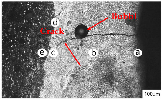
Figure 1.
Optical microscope morphology of transverse section of specimen. a-Top of clad layer. b-Mid-height of clad Layer. c-Bottom of clad layer. d-Substrate interface e-Heat-affected zone.
Through orthogonal experiments, various process parameters were adjusted to ultimately obtain the macroscopic morphology of the cladding layer (Figure 2). Some samples (e.g., Samples 2/3/4/7) exhibited noticeable cracks and voids, while others yielded favorable results (e.g., Sample 5). Cross-sectional views of the specimens are shown in Figure 3. Samples 1–9 represent nine distinct cladding layers, with the first layer exhibiting extremely low melt height and containing voids. As powder feed rate and scan speed increased, the second coating exhibited higher melt height but retained porosity. With further increases in powder feed rate and scan speed, the third coating maintained the same melt height but achieved greater melt width. The fourth coating, processed at lower powder feed rate and scan speed, demonstrated insufficient melt height and contained voids. The fifth coating achieves optimal melt height and width. The sixth coating exhibits relatively high melt height with adequate width. The seventh coating features further increased power but lower powder feed rate and scan speed, resulting in porosity and low melt height. The eighth and ninth coatings increase powder feed rate and scan speed, yet their melt height and width are suboptimal.
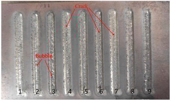
Figure 2.
Surface morphology of laser cladding specimens from orthogonal experiments.
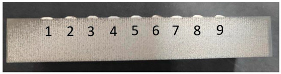
Figure 3.
Cross-Section morphology of the fused cladding layer in the orthogonal experiment.
During preparation, the substrate was polished using coarse sandpaper, and a certain roughness was retained to minimise laser reflectivity. The results show that the obtained fused cladding has no evident macroscopic penetrating cracks, defects, or pores, and there are some impurities on the surface left by the upwelling of the melting compounds, which is highly beneficial for the moulding effect.
Table 4 lists the microhardness data of the fused cladding layers measured with different process parameters as part of the orthogonal experiment.
Table 4.
The results of orthogonal experiments on the nine (33) fused cladding layers.
Microhardness is the average hardness between the top of the fused cladding layer and the heat-affected zone; it can be used to assess the wear resistance of the fused cladding layer. The orthogonal design of the experiment allowed for effective evaluation of the effect of different process parameters on the hardness of the fused cladding layer while reducing the number of experiments.
3. Results and Discussion
3.1. Micromorphology and Microstructural Analysis
Figure 4 shows the microstructure of the bottom, middle, and top of the fusion zone of the fused cladding layer. As can be seen in Figure 4a, the cross-section of the fused cladding layer is clearly divided into the fused cladding, bonding, and matrix zones. As shown in Figure 4b, the distribution of the elements in the line scans is relatively uniform and forms a sound metallurgical bond, with no defects such as cracks and holes. The dendrites start to grow from the matrix–cladding bond and gradually extend to the interior.
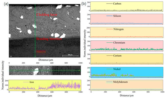
Figure 4.
Overall morphology of the cross-section of the cladding layer of Sample 2 and XRD line scan results.
Figure 5 presents SEM of the specimens with different CeO2 contents. The SEM spectra show that the fused upper layer contains martensite (the needles), carbides (the bright areas), and residual austenite (the dark areas). Figure 5a shows that the fused cladding layer of the specimen with no added CeO2 is composed of a large number of dendrites, the grain size of the microstructure is large and uneven, and the white reinforced phase is large and irregularly distributed. Adding CeO2 to the powder results in the grains of the fused cladding layer becoming finer and finer. At 1% CeO2, the size of the white reinforced phase is basically unchanged. At 1.5% CeO2, the size and distribution of the white reinforced phase very clearly change, and the shape changes from an irregular block to a more rounded spherical shape. At 2% CeO2, the spherical white reinforced phase is more diffusely distributed, as shown in Figure 5d. This is because CeO2 can be used as the core of heterogeneous nucleation to promote grain refinement, helping the molten pool to solidify uniformly, reducing segregation and defects, and making the microstructure more uniform [23].
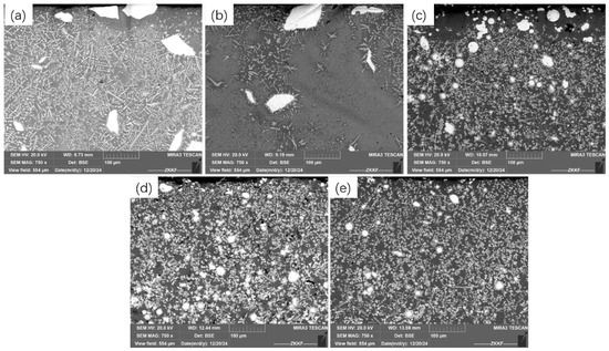
Figure 5.
Microstructure of the lower region of the cladding layer. (a) Sample 1, (b) Sample 2, (c) Sample 3, (d) Sample 4, and (e) Sample 5.
The microstructure of the central part of the fused cladding layer has undergone obvious changes: instead of a large number of coarse and brittle needle-like phases, the organisation is more refined and denser, as shown in Figure 6d. At the same time, there are more equiaxed and significantly fewer columnar grains. This microstructural change occurs because CeO2 has a high melting point, and during the cladding process, the CeO2 particles are distributed diffusely in the cladding layer, so the dendrites encounter resistance in terms of the direction of their growth. On the other hand, part of the CeO2 can become the core of heterogeneous nucleation and thus increase the nucleation rate, resulting in the growth of this part of the dendrite being limited by the growth of other dendrites. Furthermore, due to the purification effect of CeO2, the fused cladding layer phase has fewer inclusions, and CeO2 addition enhanced molten pool convection, improved fluidity, and reduced thermal gradients [24].
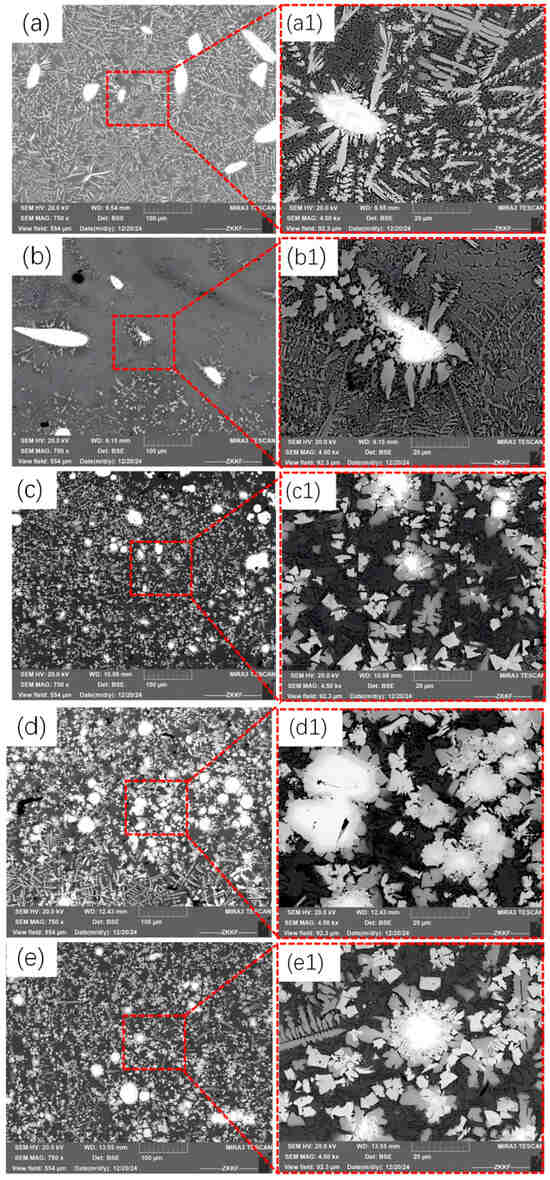
Figure 6.
Microstructural morphology of the central region of the fused cladding layer: (a) Sample 1, (b) Sample 2, (c) Sample 3, (d) Sample 4, (e) Sample 5; and the corresponding high-magnification plot: (a1) Sample 1, (b1) Sample 2, (c1) Sample 3, (d1) Sample 4, and (e1) Sample 5 with different CeO2 contents.
3.2. SEM Analysis of the 2% CeO2 Coating
Figure 7 shows the SEM and EDS analyses of typical areas of the fused cladding layer of the specimen with a 2% CeO2 content. The main chemical components of the white blocky areas are W and carbon (C), respectively, and the main chemical compositions of the black areas are Ni, W, iron (Fe), and C. Fe is believed to be diluted out of the matrix by high-temperature melting and the relative flow of the liquid under strong laser irradiation, while W is left over from the in situ reaction and is dissolved into the Ni matrix.
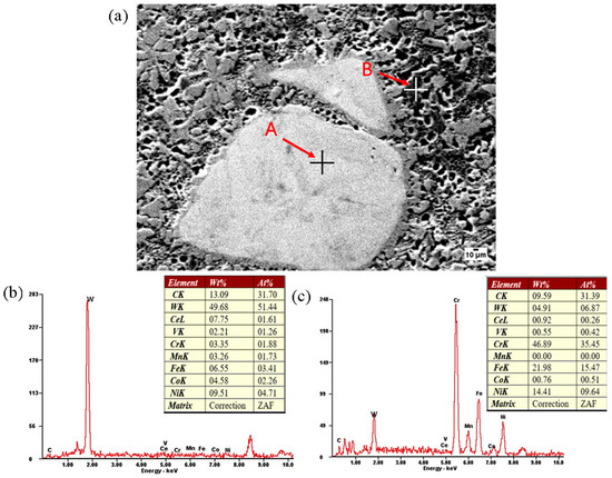
Figure 7.
Energy spectrum analysis of the 2% CeO2 specimen. (a) The microstructure of 2% CeO2 specimen, (b) Point A, (c) Point B.
3.3. XRD Analysis
Figure 8 shows the XRD analysis of the five specimens. The variation in CeO2 content only affects the peak intensity of the coatings. This finding indicates that different CeO2 contents do not significantly change the composition of the main phase of the coatings; rather, they lead to changes in its relative proportions. Based on the distribution of the diffraction peaks, the fused cladding layers with different CeO2 contents are mainly composed of nickel iron oxide (NiFe2O4) and chromium vanadate (CrVO4) phases (with Ni from the Ni-60 powder) [22,25]. In addition, carbides such as MC (where M is W or vanadium [V]) and chromium carbide (Cr23C6) precipitate in the grain boundary space, as was the case with the energy spectrum results in Figure 7. The formation of the substances is related to their Gibbs free energy, while the precipitates are affected by the melting point. Wang [26] and Zhong [27] showed that the formation of MCs (where M stands for a specific metal element) usually exhibits a lower Gibbs free energy and a higher melting point compared to reactions that occur during laser cladding. As a result, MCs (M=W,V) tend to appear and grow gradually when the molten pool solidifies. The presence of VC and WC confirms the in situ formation of the enhanced phase in the molten pool. Sufficient Cr reacts with C to produce a large number of hard phases, Cr23C6, which precipitate upon the solidification of the molten pool. The negative Gibbs free energy of these reactions suggests that they have a tendency to occur spontaneously [28,29].
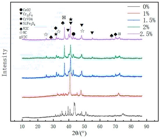
Figure 8.
X-ray diffraction diagram of the coatings’ cross-sections.
3.4. Microhardness Analysis
Hardness is an index comparing the softness and hardness of materials. In this study, the microhardness of five groups of cladding layers in laser-fused coatings with different CeO2 contents was tested. Figure 9 presents curves showing the variation in microhardness with distance for specimens coated with coatings with different CeO2 contents. The fused coatings can effectively improve the hardness of the substrate material. The microhardness changes as follows: fused cladding layer > heat-affected zone > substrate. Moreover, the microhardness of the fused cladding layer produced by adding CeO2 to Ni-60/WC increased significantly, from about 700 HV for the layer produced by laser cladding Ni-60/WC alloy alone to about 900 HV. There are two main reasons for these results. First, CeO2 can accumulate at structural defects such as dislocations, pores, and, preferentially, grain boundaries, thereby reducing the segregation of impurity elements. This plays a very important role in the repair of the microstructure [30]; the purifying and strengthening effect on the grain boundaries is evident, resulting in a potential improvement in the microhardness of the fused cladding layer. Second, due to CeO2 refinement, the structure of the grains becomes finer relative to the area of the grain boundaries, which is accompanied by a reduced tendency towards plastic deformation and thus improved microhardness. In addition, as can be seen in Figure 7, the specimen with 2% CeO2 is harder than the other specimens. This is because the microstructure of the CeO2 powder added to the fused cladding layer has undergone significant changes [31]. There is no longer a large number of coarse and brittle needle-like phases; rather, the microstructure appears more refined and denser. At the same time, there are more equiaxed grains and significantly fewer columnar grains, so the hardness of the specimen increases with increases in the CeO2 content. As the CeO2 content continues to increase, there is a reduction in the Ni-based alloy powder content. Therefore, a 2% CeO2 content has a better effect on the hardness of the coating.
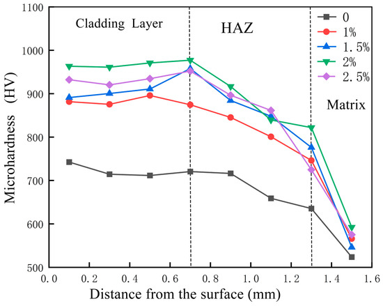
Figure 9.
The hardness of fused cladding layer specimens with different CeO2 contents.
3.5. Frictional Wear Characterisation
The frictional wear of the five groups of specimens with different CeO2 contents was evaluated on a testing machine for 900 s. As shown in Figure 10, the wear loss of the 0% CeO2 specimen was 0.0077 g. The weight loss of the different coatings over 15 min decreased as the amount of added CeO2 increased. The addition of CeO2 powder significantly improves the wear resistance of the fused cladding layer. This improvement is due to a preferential bias for CeO2 in the grain boundary, a stronger grain boundary effect, and a change in the grain boundary distribution that promotes enhanced dislocation mobility. At the same time, the inter-grain slip tendency increases, facilitating stress relaxation in surface microcracks under friction, enhancing resistance to crack propagation, and thereby reducing wear. Moreover, the eutectic microstructure is refined and the toughness of the fused cladding layer is improved and during the solidification phase, the excess of rare-earth elements accelerates the absorption rate of the cladding material, thereby enhancing energy within the molten pool and facilitating the release of more WC particles, resulting in enhanced hardness [32]. Hence, under frictional wear, the coating’s surface constantly produces plastic deformation, delaying the occurrence of crushing. Overall, the optimal amount of CeO2 addition is 2%.
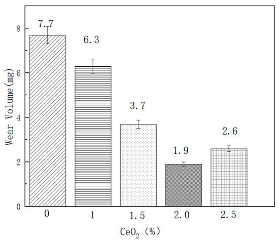
Figure 10.
Frictional wear weight loss diagram for fused cladding layers with different CeO2 contents.
4. Conclusions
In this paper, laser cladding was used to fuse WC-Ni60 composite cladding layers to the surface of Cr12MoV cold work steel, and the influence of different contents of CeO2, a rare earth oxide, on the coating’s microstructure and properties was explored. The results are as follows:
(1) The optimum process conditions—laser power of 1500 W, powder feeding at 0.1 g/s, and a scanning speed of 7 mm/s—were derived from orthogonal experiments to produce a laser-fused cladding layer with excellent performance. The optimum process parameters were used to prepare multi-channel-modified composite fusion-coated layers with different CeO2 contents for the subsequent experiments.
(2) A composite cladding layer composed of WC-Ni60 was obtained by laser-fusing cladding onto the surface of Cr12MoV cold work steel, resulting in three regions: cladding, bonding, and heat-affected zones. The structure of the composite coating is mainly composed of dendrites, cellular crystals, strip crystals, and bulk crystals. The dendrites are mainly composed of W, Fe, and Ni atoms; the cellular crystals contain C, W, and Cr atoms; and the bulk structure contains Cr, Fe, and W atoms. Upon adding CeO2, a significant change occurred in the microstructure of the middle part of the cladding layer: instead of a large number of coarse and brittle acicular phases, the microstructure became more refined and denser. At a CeO2 mass fraction of 2.0%, the reinforcing phase is more uniformly dispersed in the cladding layer.
(3) The distribution pattern of the cladding layer’s microhardness values along its depth direction is as follows: The maximum microhardness value is not on the surface, but in the layer 0.1mm below the surface. After reaching the peak, it decreases slowly, and when approaching the substrate, the hardness gradient is very large, rapidly decreasing to the hardness level of the substrate.
Based on the microhardness and frictional wear tests, the addition of 2% CeO2 significantly improves the hardness of the fused cladding layer. The frictional wear test results show that the addition of CeO2 can improve the wear resistance of the fused cladding layer and that, when the other variables in the experiment remain unchanged, the fused cladding layer containing 2% CeO2 shows the best wear resistance.
Overall, the composite Ni-60 + 35%WC + 2% CeO2 coating exhibited the best performance when fused onto the surface of Cr12MoV cold work mould steel.
Author Contributions
Methodology, W.Z. and Y.S.; Software, Y.L.; Formal analysis, Y.Z.; Investigation, B.G.; Data curation, H.X.; Writing—original draft, W.M. All authors have read and agreed to the published version of the manuscript.
Funding
This research was funded by Key scientific research projects of colleges and universities in Henan Province (No. 25B430039), the Science and Technology Program of Henan Province (Project No. 252102220126), and the Xuchang key specialized research and development breakthrough (No. 2025076 and No. 2024069).
Institutional Review Board Statement
Not applicable.
Informed Consent Statement
Not applicable.
Data Availability Statement
The original contributions presented in this study are included in the article. Further inquiries can be directed to the corresponding authors.
Conflicts of Interest
The authors declare that they have no known competing financial interests or personal relationships that could have appeared to influence the work reported in this paper.
References
- Link, J.; Teichmann, F.; Wetzel, A. An Initial Study of Ultra High Performance Concrete as Reusable Mold Material for Aluminum Casting. Materials 2025, 18, 153. [Google Scholar] [CrossRef]
- Takumi, E.; Shigeru, T.; Kouki, H.; Akihisa, K.; Kazuyuki, H. Experimental study on the application of PET thin-film optical sheets in shock imprinting technology. Sci. Technol. Energ. Mater. 2023, 84, 87–89. [Google Scholar]
- La, L.; Wang, L.; Liang, F.; Zhang, J.; Liang, G.; Wang, Z.; Qin, L. High-temperature Oxidation and Tribological Behaviors of WTaVCr Alloy Coating Prepared by Double Glow Plasma Surface Alloying Technology. Surf. Coat. Technol. 2023, 464, 129429. [Google Scholar] [CrossRef]
- Zhang, G.; Khanlari, K.; Huang, S.; Li, X.; Zhao, D.; Wu, H.; Cao, Y.; Liu, B.; Huang, Q. Dual-structured Oxide Coatings with Enhanced Wear and Corrosion Resistance Prepared by Plasma Electrolytic Oxidation on Ti-Nb-Ta-Zr-Hf High-Entropy Alloy. Surf. Coat. Technol. 2023, 456, 129254. [Google Scholar] [CrossRef]
- Behzad, P.; Reza, M.; Morteza, Y. Characterization of Wire Arc Additive Manufactured Products: A Comparison Between As-Deposited and Inter-Layer Cold Worked Specimens. J. Manuf. Process. 2020, 57, 61–71. [Google Scholar]
- Liu, Z.; Wang, C.; Mi, G.; Zhang, W.; Wang, J. Surface Morphological Evolution and Microhardness Change of Cr12MoV Steel by Pulsed Laser Polishing. Opt. Laser Technol. 2024, 171, 110419. [Google Scholar] [CrossRef]
- Gao, Y.; Jiang, S.; Tong, Y.; Bai, S.; Lu, P. Temperature Field Simulation and Experimental Confirmation of Laser Cladding High-Entropy Alloy Coating on Cr12MoV. Processes 2024, 12, 257. [Google Scholar] [CrossRef]
- Miao, X.; Wu, M.; Wang, H. Effects of La content on microstructure and tribological properties of laser clad Ni60/WC/La2O3 composite coatings on Cr12MoV. J. Mater. Res. Technol. 2024, 29, 2667–2678. [Google Scholar] [CrossRef]
- Gao, Y.; Bai, S.; Tong, Y.; Lu, P.; Liu, Y.; Zhang, D. Microstructure Evolution and Enhanced Wear Resistance of Al2CrFeNiMo High Entropy Alloy Coating Fabricated by Laser Cladding. J. Therm. Spray Technol. 2024, 33, 1472–1483. [Google Scholar] [CrossRef]
- Li, F.; Dai, W.; Wu, Z.; Xu, Y.; Wang, J.; Wang, Q. Effect of Cu content on the mechanical and tribological properties of MoN-Cu coatings deposited by HiPIMS. Surf. Coat. Technol. 2025, 497, 131769. [Google Scholar] [CrossRef]
- Jiang, Y.G.; Zhang, W.J. The influence of laser power on the microstructure and friction performance of laser-prepared TiC-NbC composite coatings on stainless steel surfaces. Mater. Today Commun. 2024, 411, 110812. [Google Scholar] [CrossRef]
- Yuan, W.; Li, R.; Chen, Z.; Gu, J.; Tian, Y. A Comparative Study on Microstructure and Properties of Traditional Laser Cladding and High-Speed Laser Cladding of Ni45 Alloy Coatings. Surf. Coat. Technol. 2021, 405, 126582. [Google Scholar] [CrossRef]
- Sun, Y.; Fu, H.; Ping, X.; Sun, S.; Lin, J.; Liang, Y. Effect of Process Parameters and Niobium Carbide Addition on Microstructure and Wear Resistance of Laser Cladding Nickel-based Alloy Coatings. Mater. Und Werkst. 2020, 51, 54–65. [Google Scholar]
- Li, Z.; Wei, M.; Xiao, K.; Bai, Z.; Xue, W.; Dong, C.; Wei, D.; Li, X. Microhardness and wear resistance of Al2O3-TiB2-TiC ceramic coatings on carbon steel fabricated by laser cladding. Cream. Int. 2019, 45, 115–121. [Google Scholar] [CrossRef]
- He, X.; Song, R.G.; Kong, D.J. Effects of TiC on the Microstructure and Properties of TiC/TiAl Composite Coating Prepared by Laser Cladding. Opt. Laser Technol. 2019, 112, 339–348. [Google Scholar] [CrossRef]
- Yang, H.; Zhang, Z.; Huang, G. Study on the Organization and Wear Resistance of In718/(2Nb+1SiC) Tool Composite Coating Based on Laser Cladding Technology. Crystals 2025, 15, 335. [Google Scholar] [CrossRef]
- Hajideh, M.R.; Farahani, M. Direct laser metal deposition cladding of IN718 on DIN 1.2714 tool steel reinforced by the SiC nanoparticles. J. Mater. Res. Technol. 2023, 23, 2020–2030. [Google Scholar]
- Zhang, Z.; Yang, F.; Zhang, H.; Zhang, T.; Wang, H.; Xu, Y.; Ma, Q. Influence of CeO2 Addition on Forming Quality and Microstructure of TiCx-reinforced CrTi4-based Laser Cladding Composite Coating. Mater. Charact. 2020, 171, 110732. [Google Scholar] [CrossRef]
- Wu, Z.H.; Miao, L.; Feng, D.Q. The effect of CeO2 addition on the microstructure and properties of laser cladding Ni-WC coatings on 45 steel surfaces. Chin. Rare Earths. 2022, 3, 101–108. [Google Scholar]
- Liang, T.; Liu, J.; Zhan, C.; Peng, S.; Pu, J. Effect of Yttrium Oxide on Microstructure and Oxidation Behavior of Cr/FeCrAl Coatings Fabricated by Extreme High-Speed Laser Cladding Process: An Experimental Approach. Materials 2025, 18, 1821. [Google Scholar] [CrossRef]
- Zhu, Y.; Li, C.; Ye, H.; Li, M.; Hu, C. Effect of nanoscale CeO2 powder on wear and corrosion resistance of Ni60A-WC coatings. Ceramics Int. 2025, 51, 10913–10932. [Google Scholar] [CrossRef]
- Xu, Z.; He, Z.; Wang, Z.; Zhang, J. Effects of CeO2 on the microstructure and properties of laser cladding 316L coating. J. Mater. Eng. Perform. 2019, 28, 4983–4990. [Google Scholar] [CrossRef]
- Sui, X.; Weng, Y.; Zhang, L.; Lu, J.; Huang, X.; Long, F.; Zhang, W. Uncovering the Effect of CeO2 on the Microstructure and Properties of TiAl/WC Coatings on Titanium Alloy. Coatings 2024, 14, 543. [Google Scholar] [CrossRef]
- Chen, L.; Zhao, Y.; Guan, C.; Yu, T. Effects of CeO2 Addition on Microstructure and Properties of Ceramics Reinforced Fe-based Coatings by Laser Cladding. Int. J. Adv. Manuf. Technol. 2021, 115, 2581–2593. [Google Scholar] [CrossRef]
- Wang, H.; Zuo, D.; Li, X.; Chen, K.; Huang, M. Effects of CeO2 Nanoparticles on Microstructure and Properties of Laser Cladded NiCoCrAlY Coatings. J. Rare Earths. 2010, 28, 246–250. [Google Scholar] [CrossRef]
- Wang, R.; Song, Z.; Wei, D.; Li, X.; Song, J.; Mo, Z.; Weng, Y.; Yang, F. Unveiling the effect of electron beam shock on the microstructure and wear resistance of Cr12MoV steel. Vacuum 2024, 226, 113347. [Google Scholar] [CrossRef]
- Zhong, L.; Xu, Y.; Liu, X.; Ye, F. Study on NbC particulate-reinforced iron matrix composite produced in situ. J. Mater. Sci. 2011, 46, 2814–2819. [Google Scholar] [CrossRef]
- He, X.; Song, R.G.; Kong, D.J. Microstructure and Corrosion Behaviour of Laser-Cladding Al-Ni-TiC-CeO2 Composite Coatings on S355 Offshore Steel. J. Alloys Compd. 2018, 770, 771–783. [Google Scholar] [CrossRef]
- Sun, S.; Fu, H.; Ping, X.; Guo, X.; Lin, J.; Lei, Y.; Wu, W.; Zhou, J. Effect of CeO2 Addition on Microstructure and Mechanical Properties of in Situ (ti, Nb)C/Ni Coating. Surf. Coat. Technol. 2019, 359, 300–313. [Google Scholar] [CrossRef]
- Zhu, R.; Zhu, C.; Wu, S.; Wan, X.; Li, G. Effect of CeO2 on Microstructure and Properties of Ni–Co-based Coatings. J. Mater. Res. Technol. 2023, 26, 7329–7339. [Google Scholar] [CrossRef]
- Zhao, F.; Guo, T.; Zhang, Y.; Wei, X.; Zhang, R.; Nan, X.; Dong, K.; Hu, D. Effect of CeO2 on Microstructure and Properties of Wear and Corrosion Resistance Martensitic Stainless Steel-Based Coating on Laser Cladding. Steel Res. Int. 2023, 94, 2200398. [Google Scholar] [CrossRef]
- Zhang, B.; Shi, W.; Lin, Y.; Jiang, L.; Wang, L.; He, K. Effect of CeO2 Content on Microstructure and Wear Resistance of Laser-Cladded Ni-Based Composite Coating. Liubricants 2024, 12, 227. [Google Scholar] [CrossRef]
Disclaimer/Publisher’s Note: The statements, opinions and data contained in all publications are solely those of the individual author(s) and contributor(s) and not of MDPI and/or the editor(s). MDPI and/or the editor(s) disclaim responsibility for any injury to people or property resulting from any ideas, methods, instructions or products referred to in the content. |
© 2025 by the authors. Licensee MDPI, Basel, Switzerland. This article is an open access article distributed under the terms and conditions of the Creative Commons Attribution (CC BY) license (https://creativecommons.org/licenses/by/4.0/).