1. Introduction
Precision manufacturing increasingly relies on computer numerical control (CNC) machine tools to achieve sub-micrometer tolerances essential for aerospace, automotive, medical, and energy sectors. In multi-axis machine tools, structural loop cross-talk induces position-dependent geometric errors (PDGEs) that vary with multiple axis coordinates, invalidating the single-variable assumption in conventional volumetric error models. Even small geometric deviations can accumulate to degrade part quality, assembly reliability, and overall productivity. Recent studies report that geometric errors contribute to more than 40% of dimensional deviations in stable machining, often exceeding thermal and dynamic effects [
1,
2]. Ensuring geometric accuracy is therefore critical not only for product performance but also for cost efficiency and industrial competitiveness.
Machine tool accuracy is determined by the structural loop linking tool and workpiece, which accumulates positioning, straightness, squareness, and angular errors. Conventional volumetric error models are typically developed under the independent-axis assumption, in which each error is treated as a function of its own axis coordinate. Linear or polynomial interpolation based on sparse measurements is then applied, and error maps are embedded into CNC compensation modules [
3,
4,
5]. These approaches have demonstrated long-standing effectiveness, and substantial progress has been achieved in rigid-body modeling, laser interferometry calibration, and compensation algorithms [
6]. Recent developments also extend these frameworks to thermal error modeling [
7,
8], servo dynamics [
9,
10,
11], and data-driven learning [
12,
13,
14].
However, as machine tools evolve toward larger workspaces and higher speeds, the independent-axis assumption becomes inadequate. In stacked configurations such as X–Y cross-slides, axis motions are mechanically coupled, producing structural loop cross-talk. This effect generates position-dependent geometric errors (PDGEs) that vary with multiple axis coordinates, making single-variable models invalid [
15,
16,
17]. Although polynomial surfaces and spline interpolation have been investigated, most existing work either neglects cross-talk or requires complex external metrology [
18,
19,
20]. Furthermore, single-variable interpolation fails to capture nonlinearities, resulting in residual errors during coupled motions. Efficient and smooth multi-variable prediction methods that are compatible with real-time CNC cycles remain scarce. Recent research has demonstrated increasing interest in modeling cross-axis coupling and compensation. Fan et al. introduced an enhanced volumetric error model explicitly including cross-talk terms with ISO 230-6 validation [
21]. Gao et al. reviewed calibration–modeling–compensation methods highlighting the move toward controller-level integration [
22]. Wang et al. analyzed inter-axis error transfer and cross-coupled control for five-axis machines [
23]. Yin et al. introduced a dual-quaternion-based kinematic identification method for geometric errors in rotary axes, which provided more accurate decoupling between translational and rotational deviations [
24]. Recent progress on NURBS and dual-NURBS interpolation enables embedding multivariable geometric-error surfaces into CNC cycles [
25,
26]. These studies further motivate our development of a real-time multi-variable prediction and compensation framework. In addition, the integration of real-time error compensation often depends on the openness of the CNC architecture in industrial practice. Most high-end CNC systems (e.g., Siemens, Fanuc, Heidenhain) adopt closed control structures, while the secondary development ecosystem of domestic controllers is still evolving. These factors limit the online modification of embedded compensation models and pose challenges for real-time implementation and cross-platform deployment.
To address these gaps, this study proposes a data-driven framework for predicting and compensating cross-talk-induced PDGEs in CNC machine tools. We benchmark three models: a conventional single-variable interpolation method, an improved bilinear interpolation model, and a non-uniform rational B-spline (NURBS)-based formulation capable of representing complex error surfaces. All models are embedded directly into the interpolation kernel of a commercial CNC controller to enable real-time compensation without additional hardware. Dense on-machine measurements are employed to construct error maps, and compensation performance is evaluated through ISO 230-6 planar diagonal tests [
27].
The remainder of this paper is structured as follows.
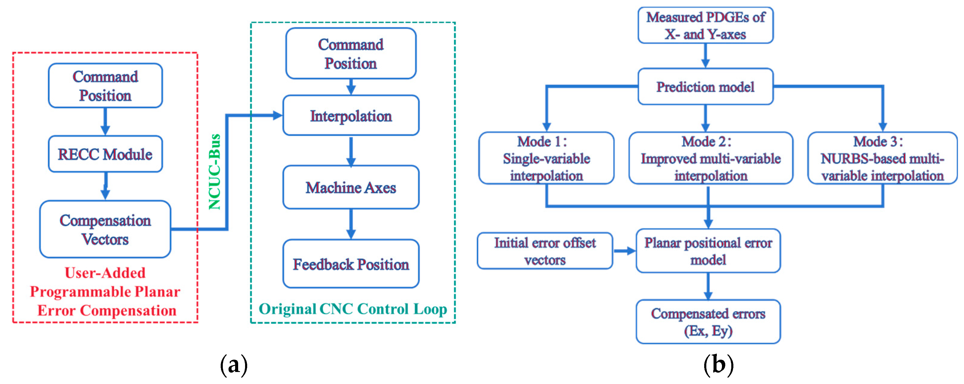
Section 2 introduces the machine tool configuration, measurement strategy, and embedded sensor system for PDGE acquisition.
Section 3 develops the three prediction models, from single-variable interpolation to multi-variable bilinear and NURBS-based formulations.
Section 4 details the real-time error compensation controller integrated into the CNC kernel.
Section 5 reports experimental validations, including planar diagonal accuracy verification. Finally,
Section 6 summarizes the contributions.
3. Prediction Models for PDGEs with Cross-Talks
3.1. Conventional Single-Variable Interpolation Model
The conventional single-variable interpolation model constitutes the baseline approach for predicting PDGEs in machine tools. In this method, the error along a given axis is treated as a one-dimensional function of its position. Suppose that
pi and
pi+1 are two adjacent measurement points along axis
i, and that
eji denotes the error component in direction
j induced by the motion of axis
i. For an arbitrary intermediate position
p ∈ [
pi,
pi+1], the error is estimated by linear interpolation as (1) [
28], which follows the conventional one-dimensional interpolation formulation widely used in geometric-error compensation.
Equivalently, by introducing a normalized interpolation parameter
t = (
p −
pi)/(
pi+1 −
pi) (0 ≤
t ≤ 1), the model can be expressed as a weighted average of the neighboring error measurements:
This baseline method assumes that the error in each Cartesian direction depends only on the corresponding single axis position, and errors are interpolated linearly between measured nodes. It is noted that a fundamental limitation of this model is that cross-axis interactions are entirely neglected. In regions where structural loop cross-talk effects are significant, such as when two or more axes move simultaneously, the single-variable assumption becomes invalid. As a result, large residual errors are observed in coupled motion regions, motivating the development of multi-variable interpolation models to improve prediction accuracy.
3.2. Improved Multi-Variable Interpolation Model
To address the limitation of the single-variable interpolation approach, an improved multi-variable interpolation model is introduced. In this model, the PDGE is considered as a function of two coupled axis positions rather than a single axis coordinate. This extension enables the model to explicitly capture cross-talk effects in the structural loop.
Let
eji denote the error component in direction
j induced by the motion of axis
i. Suppose that four neighboring measurement points in the (
x,
y) plane are given by (
x0,
y0), (
x1,
y0), (
x0, y1), and (
x1,
y1) with the corresponding error values
eji (
x0,
y0),
eji (
x1,
y0),
eji (
x0,
y1),
eji (
x1,
y1). For an arbitrary query point (
x,
y) located in the rectangle defined by these nodes, the error is interpolated bilinearly as (3) [
20], consistent with recent implementations of two-dimensional interpolation in error-field reconstruction for CNC machine tools.
where
The bilinear interpolation method was selected for this study due to its favorable balance between accuracy and computational efficiency. It requires only four neighboring data points and involves limited computational effort; making it well suited for real-time implementation within a CNC controller. However; although bilinear interpolation significantly improves prediction accuracy over the single-variable model; its piecewise linear nature may lead to limited smoothness in representing complex error distributions. To further enhance spatial fidelity and continuity across the coupled plane; a more advanced surface representation based on non-uniform rational B-splines (NURBS) is introduced in
Section 3.3.
3.3. NURBS-Based Multi-Variable Interpolation Model
Building upon the motivation outlined in
Section 3.2, a non-uniform rational B-spline (NURBS)-based multi-variable interpolation model is established to provide a smoother and more accurate representation of cross-talk errors across the coupled axes. The NURBS formulation enables continuous surface modeling of PDGEs over the full working plane and offers several key advantages for error prediction and real-time compensation. It allows local modification of control points without affecting the entire surface, preserves strong convex hull properties that enhance stability, and supports the definition of non-uniform knot intervals, which improves convergence and approximation performance. Moreover, as the surface is defined with relatively few parameters, the NURBS model offers a compact and efficient mathematical representation of free-form error surfaces. This compactness reduces computational overhead and facilitates integration into CNC real-time compensation modules.
Mathematically, a NURBS surface can be regarded as a two-dimensional extension of a NURBS curve. An
r ×
s degree NURBS surface for the error component
eji, where
eji denotes the error in direction
j induced by the motion of axis i, is expressed as (5) [
26], following the standard NURBS-surface definition used in recent geometric-error modeling and interpolation studies.
where {
} are the control vertices forming a two-dimensional grid for the error component
eji, {
wkl} are the weights of the control vertices, and
Nk,r (
u),
Ml,s (
v) are the B-spline basis functions of degree
r and
s defined on knot vectors
U and
V, respectively.
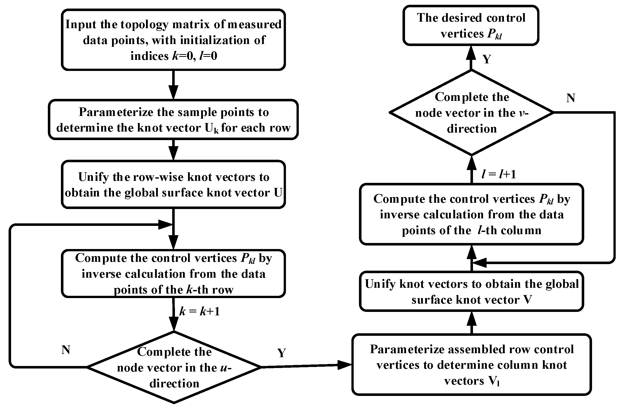
In this study, the cross-talk measurement values of the X- and Y-axis PDGEs obtained in experiments were organized into an 11 × 11 topology matrix, which served as the input dataset for constructing the surface. The interpolation procedure, illustrated in
Figure 4, defines the parameter
u along the section-line direction and the parameter
v along the vertical direction. First, the sample points in the
u-direction were used to compute the knot vectors and to determine the control vertices of each curve. The knot vectors of all curves were then unified using the averaging method to generate the global knot vector
U. The curve control vertices were subsequently treated as new data points for interpolation in the
v-direction, from which the control vertices and knot vector
V were determined. By combining the results in both directions, the full NURBS surface and its control net were reconstructed, yielding a smooth and accurate approximation of the cross-talk error surface across the working plane.
The topology matrix of 11 × 11 nodes was selected as an appropriate trade-off between spatial resolution and computational efficiency. Preliminary evaluations showed that denser grids (e.g., 15 × 15 or higher) produced only marginal improvements in prediction accuracy while significantly increasing interpolation time, which is unfavorable for real-time CNC execution. Conversely, sparser grids (e.g., 7 × 7 or 9 × 9) could not adequately capture localized nonlinear variations in the cross-talk error field. Therefore, the 11 × 11 matrix provided sufficient smoothness and precision for NURBS surface reconstruction within the 2–4 ms interpolation cycle of the CNC controller.
Compared with the bilinear interpolation model discussed in
Section 3.2, the NURBS-based multi-variable interpolation model offers superior smoothness and prediction accuracy. Nonlinear variations in cross-talk effects are effectively captured, and the compact representation ensures that the computational overhead remains compatible with the 2–4 ms CNC interpolation cycle. Consequently, the NURBS-based model provides the most accurate and reliable foundation for the real-time error compensation controller presented in the next section.
5. Experimental Validation
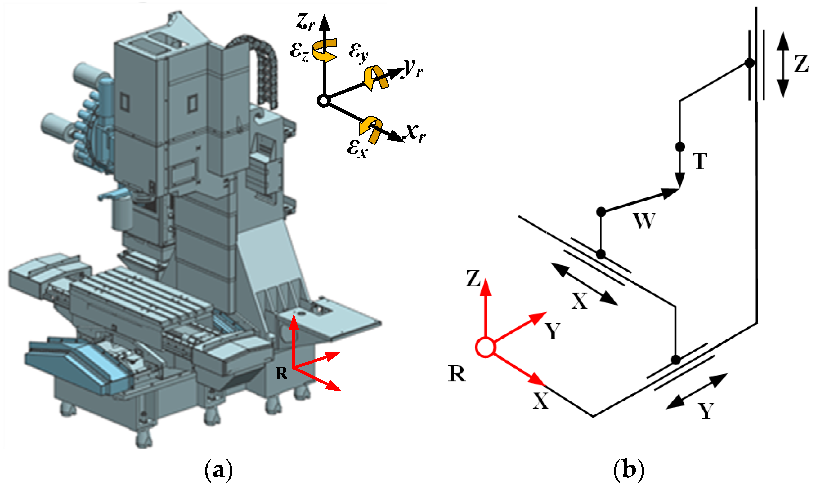
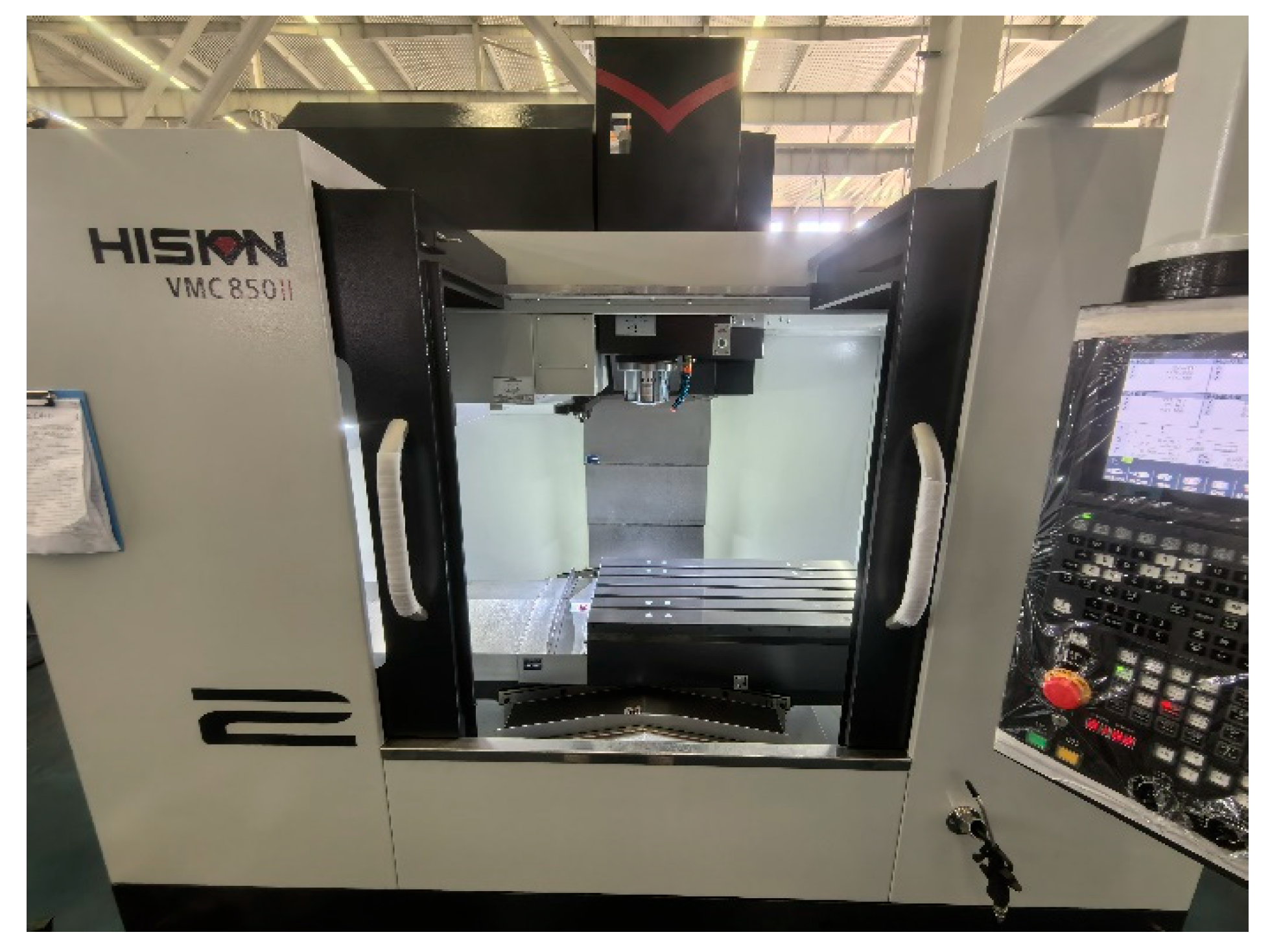
The experimental validation of the proposed prediction and compensation framework was carried out on a VMC850HS PLUS vertical machining center manufactured by Ningbo Haitian Precision Machinery Co., Ltd. (Ningbo, China), as illustrated in
Figure 6. The machine provides axis travels of 850 mm, 500 mm, and 500 mm along the X-, Y-, and Z-directions, respectively, and is equipped with an HNC-818D CNC controller, which enables real-time implementation of the developed error compensation strategies. The repeatability of the X/Y/Z axes is 0.006/0.005/0.005 mm, and the positioning accuracy is 0.010/0.008/0.008 mm, with a maximum feed rate of 36 m/min along each axis.
5.1. Error Measurement Experiments
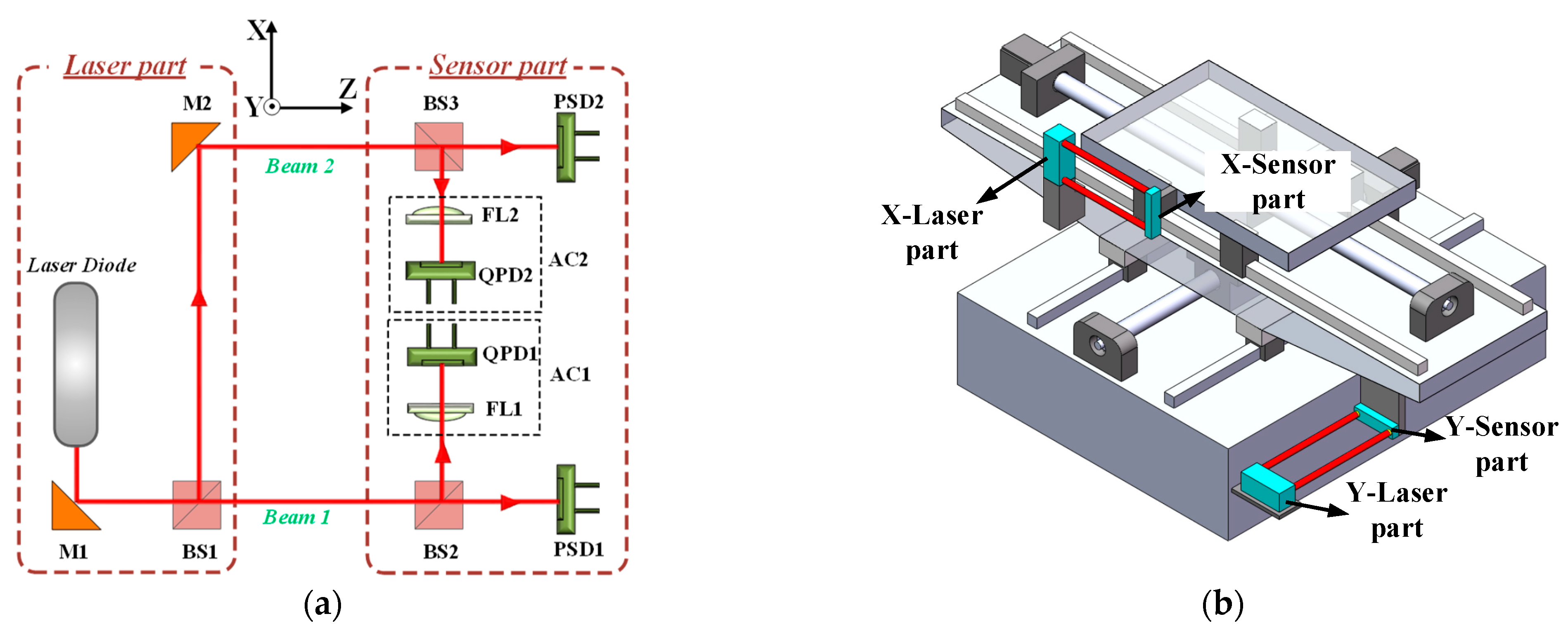
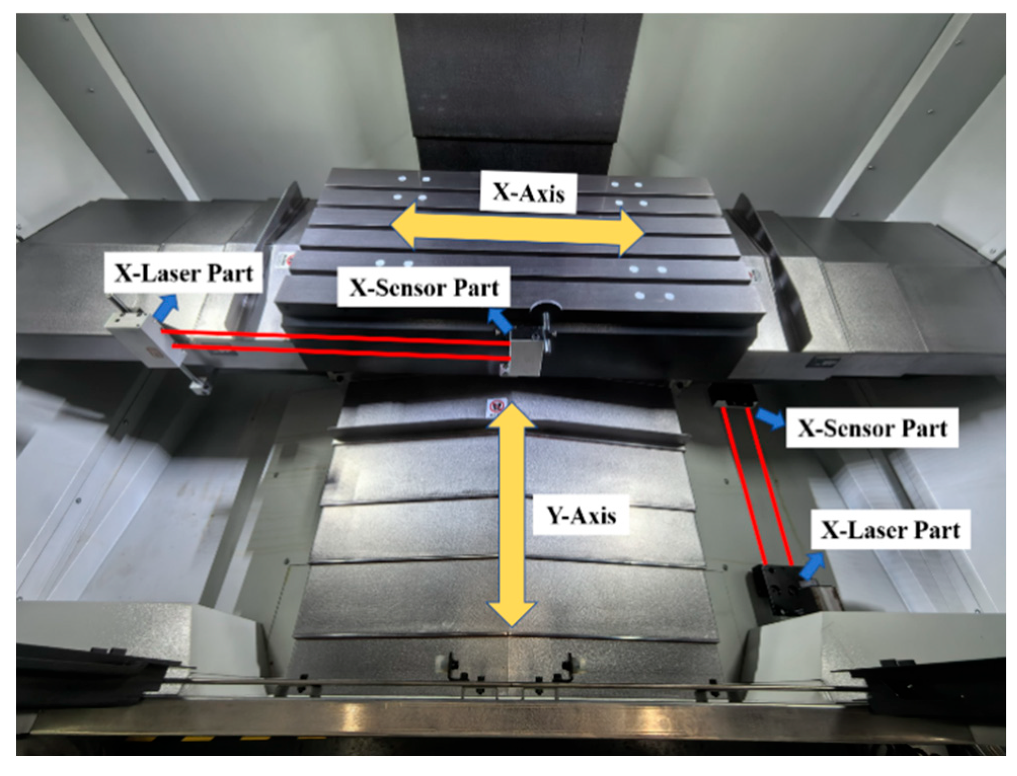
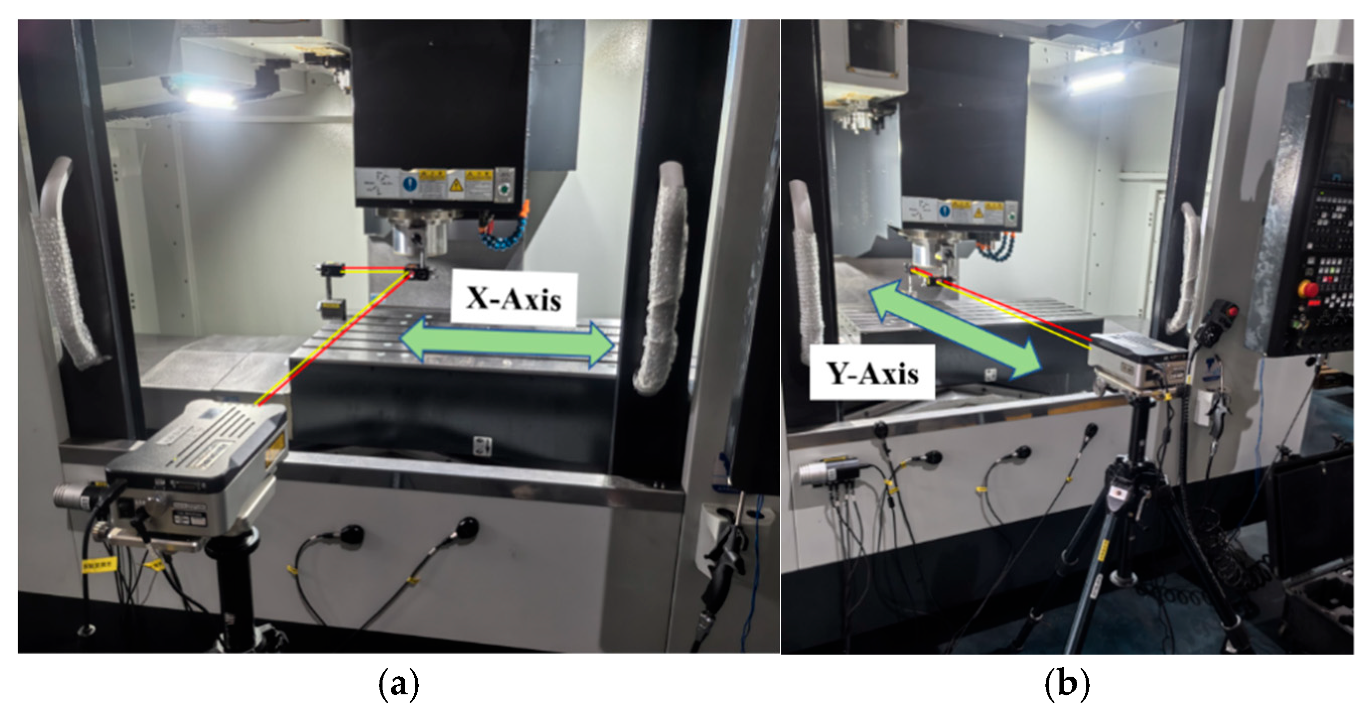
The experimental setup of the embedded 5-DOF sensor modules installed on the machine tool is shown in
Figure 7. These modules enabled simultaneous acquisition of straightness and angular error components during axis motion, providing comprehensive data for analyzing structural loop cross-talk effects.
Prior to data collection, the experiments were conducted under ambient workshop conditions, with a temperature of 20 ± 1 °C and relative humidity of 45% ± 5%. The machine tool was allowed to reach thermal equilibrium for at least two hours before measurements. The error data were collected via a self-developed sensor interface, and the interpolation as well as compensation algorithms were compiled into a C-based dynamic link library (DLL) and embedded into the kernel of the Huazhong HNC-818D CNC controller for real-time execution.
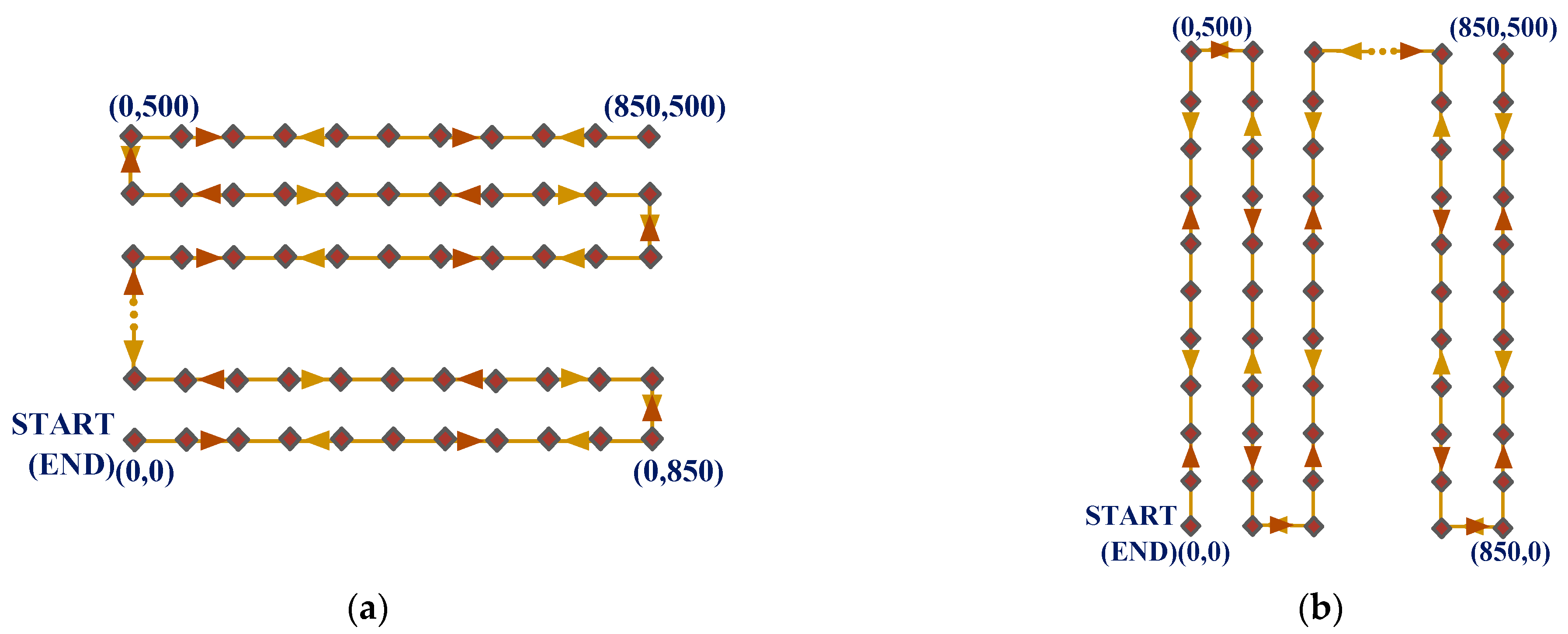
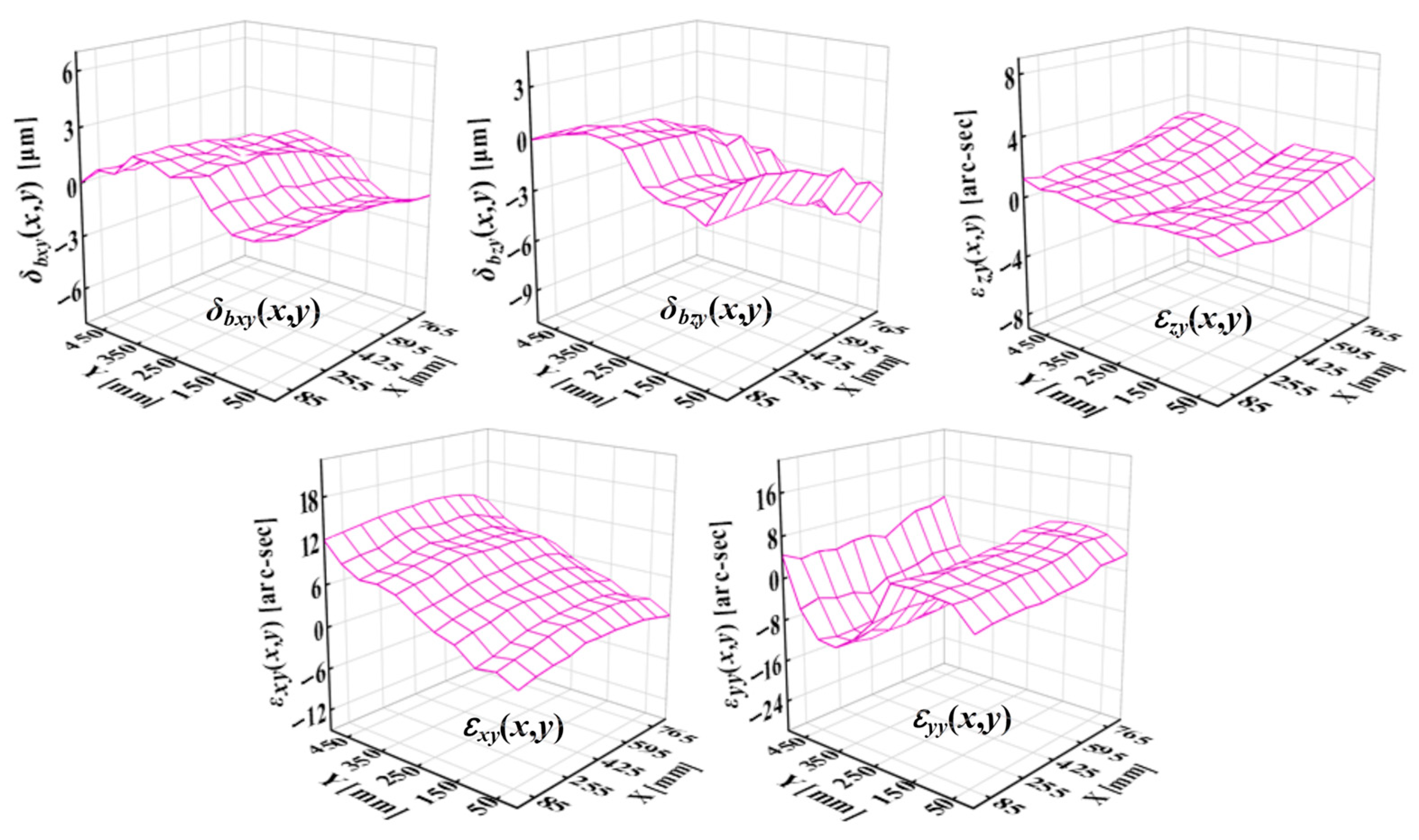
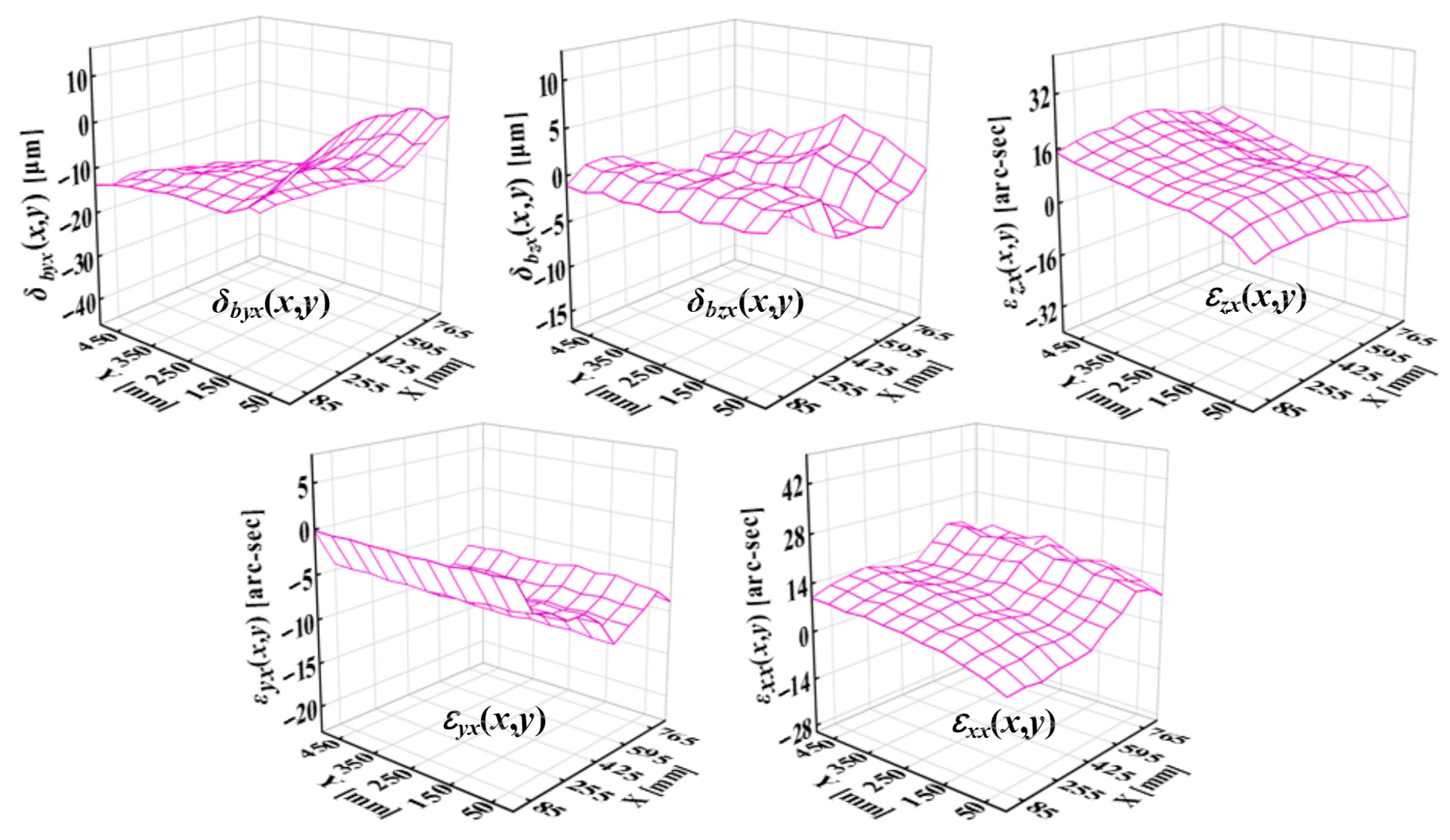
Figure 8 presents the measured PDGEs of the Y-saddle under X-axis motions at different Y positions. The results indicate that cross-talk errors strongly influence the vertical straightness error
δbzy, as well as pitch error
εxy and roll error
εyy. Similarly,
Figure 9 shows the PDGEs of the X-table under Y-axis motions at different X positions. In this case, the coupling primarily affects the horizontal straightness error
δbyx, the yaw error
εzx, and
εxx. These observations confirm that structural loop cross-talks have significant and direction-dependent impacts on specific PDGE components, underscoring the necessity of adopting multi-variable prediction models to capture such coupling effects accurately.
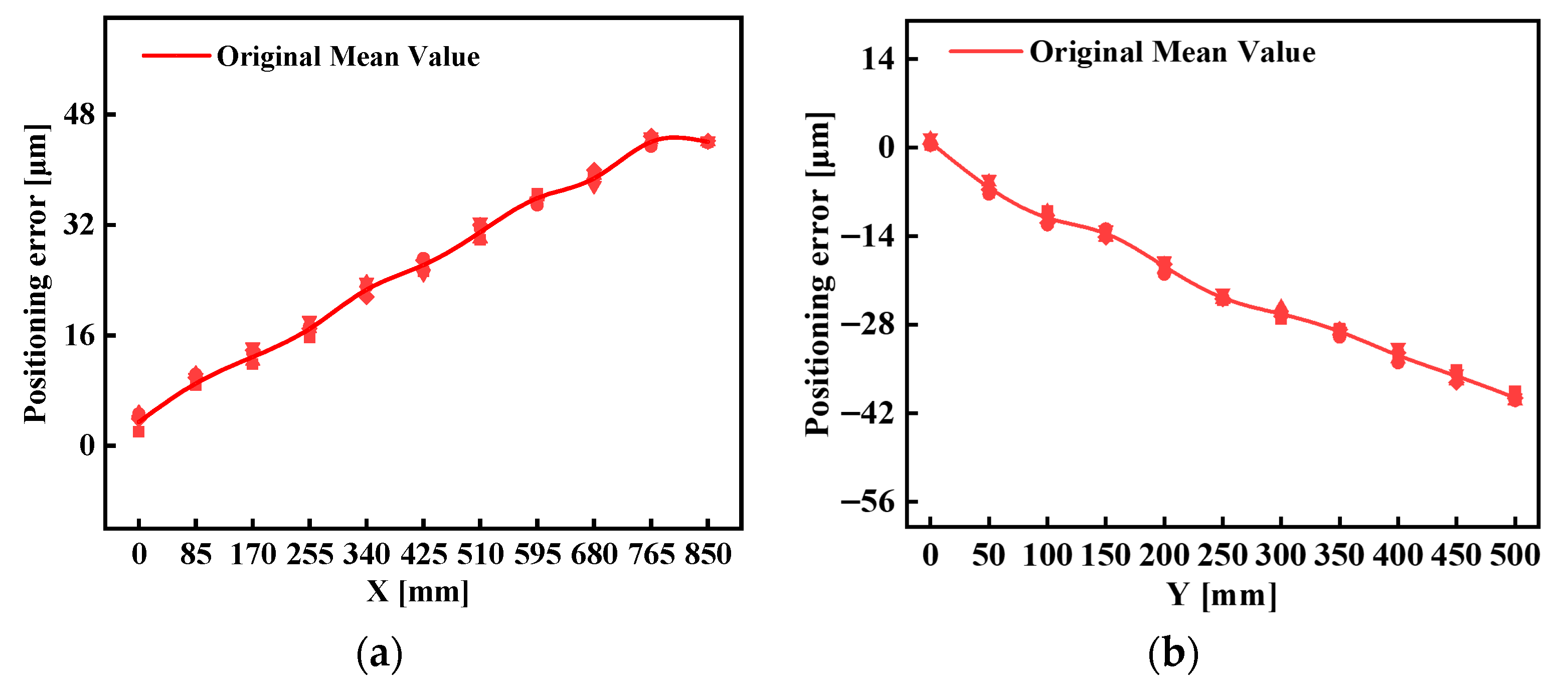
The positioning feedback of the linear axes in the investigated vertical machining center is provided by rotary encoders, with the Abbe point defined at the center of the ballscrew nut. To quantify the positioning deviations at these reference points, a high-precision laser interferometric system was employed. The XL-80 interferometer (Renishaw, Wotton-under-Edge, UK), with a specified accuracy of ±0.5 ppm and a linear resolution of 1 nm, was used to measure the positioning errors of the X- and Y-axes. The experimental setups for these measurements are shown in
Figure 10a,b. By establishing the Abbe point as the measurement reference, the obtained error data can be consistently transferred to the TCP using the vector transfer method.
Figure 11a,b present the spatial positioning errors at the Abbe points of the X- and Y-axes. Each measurement was repeated five times, and the averaged results were used for analysis. The peak-to-valley (P–V) values of the positioning errors were found to be 47 µm for the X-axis and 39 µm for the Y-axis. These errors include contributions from systematic deviations, cosine errors, and Abbe offsets. The results highlight the necessity of incorporating Abbe-referenced positioning errors into the planar positional error model in order to accurately account for their influence on the tool center point.
5.2. Planar Diagonal Accuracy Verification Experiments
Following this ISO 230-6 [
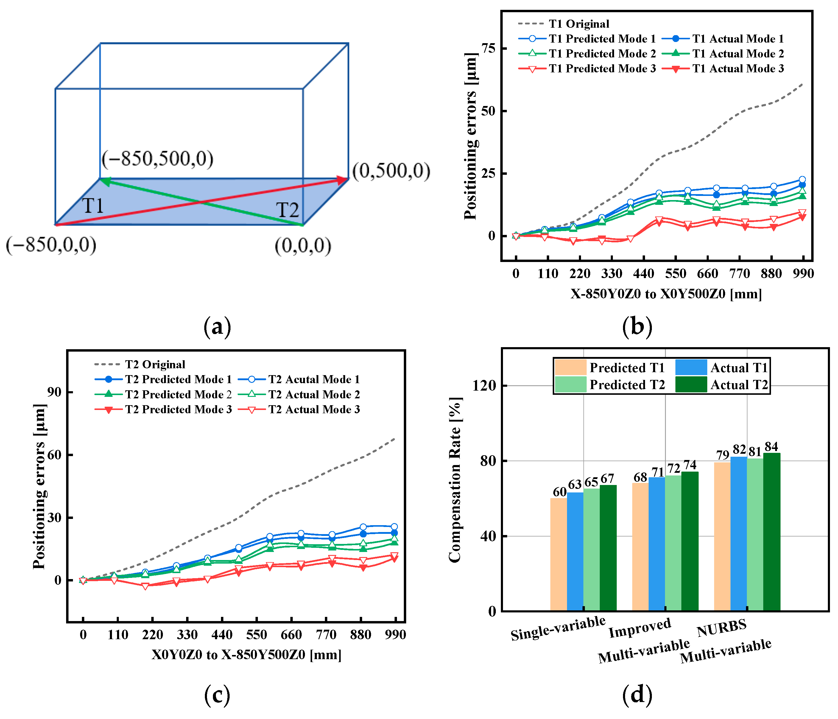
27], two planar body diagonals T1 and T2 in the XY plane are selected, shown in
Figure 12a. A laser interferometer with Renishaw XL-80 recorded the positioning error along each diagonal before and after compensation with the three prediction models. Planar body diagonal tests were performed to verify the effectiveness of the proposed prediction models in improving positioning accuracy under cross-talk conditions. The results for the two selected diagonals, denoted as T1 and T2, are presented in
Figure 12b–d.
For diagonal T1 (
Figure 12b), the uncompensated peak-to-valley (P–V) positioning error was 61.7 μm. After applying error compensation, the single-variable interpolation model reduced the error by 60% for the predicted result and 63% for the measured result. The improved multi-variable model achieved reductions of 71% and 68%, respectively, while the NURBS-based multi-variable model delivered the best performance, with reductions of 79% and 82% relative to the uncompensated case. According to Equation (5), the model-predicted residual error for T1 demonstrates excellent prediction accuracy.
For diagonal T2 (
Figure 12c), the uncompensated P–V error was 67.7 μm. After compensation, the single-variable interpolation model reduced the error by 65% for the predicted result and 67% for the measured result. The improved multi-variable model achieved reductions of 72% and 74%, while the NURBS-based multi-variable model again performed best, reducing the error by 81% and 84%. According to Equation (5), the model-predicted residual error for T2 also confirms excellent prediction accuracy.
The comparative results for both diagonals are summarized in
Figure 12d. Across T1 and T2, the single-variable model consistently reduced the error by approximately 60%–67%, whereas the improved multi-variable interpolation achieved 68%–74%, confirming the advantage of explicitly modeling cross-axis dependencies. The NURBS-based multi-variable model outperformed both alternatives, achieving reductions of 79%–84%. In particular, the actual NURBS-based multi-variable model consistently showed the best compensation capability, reducing planar diagonal errors by more than 82% on T1 and 84% on T2.
These results demonstrate that multi-variable interpolation substantially improves compensation effectiveness compared with the single-variable baseline, and that the NURBS-based surface formulation provides the highest spatial fidelity and accuracy among the three models. The consistent improvements across both diagonals confirm the robustness of the proposed modeling and compensation framework in mitigating cross-talk-induced errors in planar motion.
6. Conclusions
This study investigated structural loop cross-talk in a three-axis CNC machine tool and proposed a data-driven framework for error prediction and compensation. By employing dense grid measurements of position-dependent geometric errors (PDGEs), three interpolation models were developed and compared: single-variable, improved bilinear multi-variable, and NURBS-based multi-variable formulations. Planar diagonal verification experiments demonstrated that cross-talk significantly affects positioning accuracy, and that moving from single-variable to multi-variable prediction markedly improves both modeling and compensation. The NURBS-based approach achieved the highest spatial fidelity, reducing planar diagonal errors by more than 80% and yielding an additional 18%–19% accuracy improvement over the baseline. To enable practical application, a real-time error compensation controller was designed and embedded into the interpolation kernel of an HNC-818D CNC system, ensuring in-cycle operation without external hardware. The framework is compact, computationally efficient, and independent of mechanical modeling, providing a scalable solution for improving geometric accuracy in precision machine tools. In terms of economic feasibility, the proposed framework requires only software integration into existing CNC systems and low-cost optical sensor modules. No additional hardware modification is needed, making the method suitable for practical industrial deployment.
The research novelty of this study lies in three key aspects: (1) the development of a data-driven NURBS-based multi-variable interpolation model that, for the first time, enables accurate prediction of structural loop cross-talk-induced geometric errors within the CNC interpolation cycle; (2) the realization of a fully embedded real-time error compensation controller directly integrated into a commercial CNC kernel without any external hardware or post-processing interface; and (3) the experimental validation demonstrating over 82% reduction in planar diagonal errors, confirming both the theoretical innovation and industrial applicability of the proposed method. These novelties collectively advance the state of machine tool geometric error modeling from single-variable assumptions toward fully coupled, controller-level, data-driven compensation frameworks.
