Abstract
The exploitation of China’s oil and gas resources has advanced into the “ten-thousand-meter” ultra-deep realm. Downhole tubulars and well control equipment materials face severe corrosion challenges under the extreme high-temperature, high-pressure, and highly acidic environments prevalent in such formations. However, the corrosion mechanisms and patterns of materials under these harsh conditions remain insufficiently elucidated, necessitating systematic research. This study focuses on the typical casing material P110SS, investigating its corrosion behavior in high-temperature, high-pressure H2S/CO2 environments. The results show that at a partial pressure of H2S of 0.5 MPa, the corrosion rate of P110SS increases with temperature. A significant increase in the corrosion rate and the occurrence of pitting corrosion were observed between 100 °C and 140 °C. The corrosion product transformed from mackinawite to pyrrhotite. At 60 °C, increasing the partial pressure of H2S led to a slight increase in the corrosion rate, while at 160 °C, the corrosion rate slightly decreased. However, temperature changes did not cause any alteration in the corrosion products.
1. Introduction
With the deepening development of oil and gas resources, exploration in China has extended into deep and ultra-deep wells [1,2,3]. These downhole environments, characterized by high temperature, pressure, and high concentrations of H2S/CO2, present severe corrosion risks to oil tubulars [4,5,6]. Field investigations in the Tarim Oilfield revealed temperatures exceeding 160 °C and H2S concentrations above 600 mg/m3, making the corrosion behavior of low-alloy steel tubulars under such extreme conditions unclear and requiring further study.
The corrosion of low-alloy tubulars is influenced by the composition and structure of corrosion products [7]. For CO2 corrosion, FeCO3 is the dominant product, with corrosion rate increasing initially with temperature and CO2 partial pressure, then decreasing at higher temperatures due to changes in product coverage [8], and transitioning from uniform to localized corrosion [9]. In H2S environments, multiple corrosion products form, evolving with environmental conditions [10,11,12,13]. Huang et al. [14,15] found that at low H2S partial pressures, FeCO3 forms and the corrosion rate is high due to its porous structure. As H2S partial pressure increases (below 2 MPa), the formation of iron sulfides like mackinawite creates a denser film, reducing the corrosion rate. Yu et al. [16,17,18] observed that at lower temperatures, mackinawite predominates early on, followed by pyrrhotite, and eventually pyrite, causing initial corrosion rate increases followed by decreases. Wen et al. [19] noted that higher temperatures and H2S concentrations lead to structural changes in FeS and Fe3S4, enhancing the stability of the corrosion product films.
Currently, there is a considerable amount of research on CO2 corrosion [20,21,22,23,24,25], with various theories available to explain its corrosion mechanisms, such as the Waard-Milliams type CO2 corrosion model and the Nesic type CO2 corrosion model [26,27]. However, systematic studies on the corrosion behavior of materials under extreme conditions in ultra-deep wells (high temperature, high H2S/CO2 partial pressures) remain insufficient. This study investigates the corrosion behavior of P110SS, a commonly used sour-service material, using formation water from the Tarim Oilfield under simulated ultra-deep well conditions. It focuses on corrosion rate, product morphology, composition, and the ion selectivity of the corrosion film, aiming to clarify the impact of H2S partial pressure and temperature on corrosion mechanisms.
2. Experiment
The material used in this study is P110SS low-alloy steel, with its composition detailed in Table 1.

Table 1.
Composition of P110SS low-alloy steel (wt %).
Corrosion weight-loss experiments were conducted using a high-temperature and high-pressure autoclave to simulate downhole conditions. Specimens were first processed into dimensions of 50 mm × 10 mm × 3 mm (length × width × thickness) for hanging. The specimens were then polished sequentially with 240#, 400#, and 800# sandpaper to achieve a smooth surface. After polishing, the specimens were ultrasonically cleaned in acetone to remove surface oil. The mass of each specimen was recorded before the experiment. The experimental conditions for Experiment 1 are detailed in Table 2, and those for Experiment 2 are outlined in Table 3. Experiment 1 was conducted at 60 °C and 160 °C in a completion fluid, with H2S partial pressures of 0.1 MPa and 0.5 MPa, and a flow rate of 2 m/s. The experimental duration was 30 days. Experiment 2 was performed at an H2S partial pressure of 0.5 MPa, with temperatures of 60 °C, 100 °C, 140 °C, and 180 °C, while other conditions remained unchanged. Nitrogen was continuously introduced at the start of the experiment to displace oxygen from the autoclave.

Table 2.
Corrosion Mass Loss Conditions at Different H2S Partial Pressures.

Table 3.
Corrosion Mass Loss Conditions at Different Temperatures.
After the experiment, the specimens were placed in anhydrous ethanol to prevent oxidation and dried using a blow dryer. Macroscopic corrosion morphology was then recorded. Specimens used to calculate the corrosion rate were cleaned with an acid solution (900 mL hydrochloric acid + 100 mL distilled water + 3.5 g hexamethylenetetramine) to remove surface corrosion products. After cleaning, the dimensions (length, width, and height) of the specimens were measured, and their mass was recorded. For specimens not subjected to acid cleaning, a field emission scanning electron microscope (Quanta 200 FEG, FEI Company, Hillsborough, OR, USA) was used to observe the micro-surface morphology of the corrosion products. X-ray diffraction (XRD) analysis (Bruker D8, Bruker AXS GmbH, Karlsruhe, Germany) was performed to identify the composition of the corrosion products.
Ion selectivity is typically characterized using the membrane potential method. Before conducting the experiment, the corrosion product film was scraped off from the specimen and ground into powder using a mortar. The ground corrosion products were then mixed with 0.5 g of cellulose acetate and dissolved in 50 mL of acetone. Ultrasonic dispersion was applied to ensure uniform distribution. The solution was then poured into a glass dish to allow the acetone to evaporate, resulting in the preparation of a corrosion product membrane with a cellulose acetate framework.
The experiment was conducted following the method of Miyuki [28], and the schematic diagram of the apparatus is shown in Figure 1 [29]. The prepared corrosion product membrane was placed between two containers. The solution in the left container consisted of potassium chloride at varying concentrations of 0.0001 mol/L, 0.001 mol/L, 0.01 mol/L, 0.1 mol/L, and 1 mol/L. The solution in the right container was also potassium chloride, but with a fixed concentration of 0.01 mol/L. Due to the ion selectivity of the corrosion product membrane, the ion migration rates in the two containers will differ, resulting in a disparity in the number of cations and anions on each side. This will generate a potential difference across the membrane, known as the membrane potential.
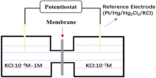
Figure 1.
Membrane potential test device. Adapted from [29].
3. Results and Analysis
3.1. Corrosion Rate
Figure 2 illustrates the corrosion rates of P110SS under different H2S partial pressures and temperatures. Overall, the effect of H2S partial pressure on the corrosion rate is minimal. At 60 °C, when the H2S partial pressure increased from 0.1 MPa to 0.5 MPa, the corrosion rates were 0.1512 mm/a and 0.1610 mm/a, respectively. At 160 °C, the corrosion rates were 1.7122 mm/a and 1.6943 mm/a. In comparison to H2S partial pressure, temperature had a more significant impact on the corrosion rate. At a constant H2S partial pressure of 0.5 MPa, the corrosion rate at 60 °C was 0.1610 mm/a. When the temperature increased to 100 °C, the corrosion rate rose to 0.1736 mm/a, indicating an accelerated corrosion process. As the temperature further increased to 140 °C, the corrosion rate sharply rose to 1.669 mm/a. At 180 °C, the corrosion rate increased slightly to 1.8041 mm/a compared to 140 °C, but the rate of increase slowed. Overall, the corrosion rate increases with temperature, with a marked rise observed between 100 °C and 140 °C. This suggests that, under a fixed H2S partial pressure, temperature changes significantly influence the corrosion rate, especially between 100 °C and 140 °C, where the corrosion process is notably affected.
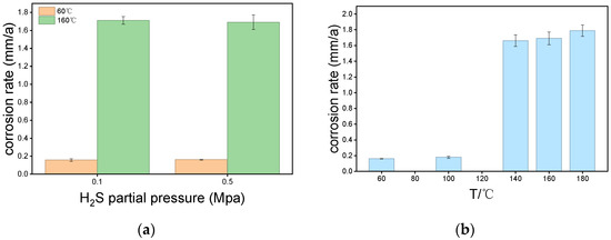
Figure 2.
(a) Corrosion rate of P110SS at different H2S partial pressure; (b) Corrosion rate of P110SS at different temperature.
3.2. Macroscopic Corrosion Morphology
As shown in Figure 3, there are distinct macroscopic corrosion morphologies of P110SS under varying H2S partial pressures and temperatures. Under constant temperature conditions, changes in H2S partial pressure have limited impact on the corrosion extent: at 60 °C, increasing the H2S partial pressure has minimal effect on the corrosion products on the substrate surface; at 160 °C, as the H2S partial pressure increases, the color of the corrosion products gradually darkens, and the detachment of the corrosion products becomes more pronounced. Under constant H2S partial pressure, corrosion generally intensifies with increasing temperature: at 60 °C and 100 °C, corrosion is relatively mild. At 60 °C, the surface morphology remains intact with no corrosion product detachment, while at 100 °C, slight detachment of corrosion products is observed. At 140 °C and 180 °C, the corrosion product layer significantly thickens, exhibiting a rough, bubble-like structure, and the corrosion severity increases markedly.
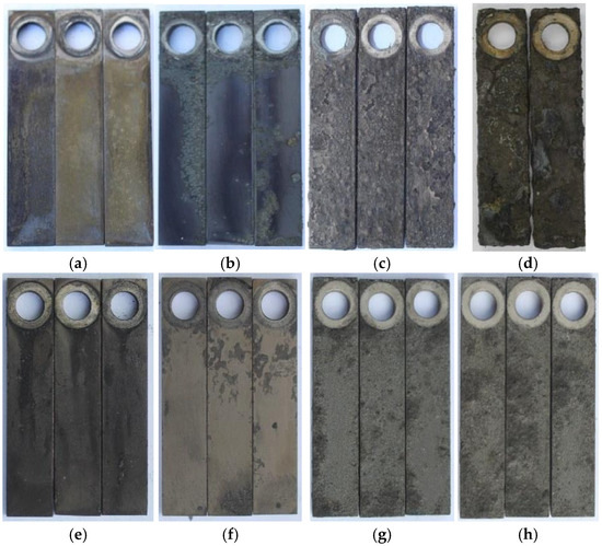
Figure 3.
Macroscopic photos of P110SS at different H2S partial pressures and temperatures, (a) 60 °C, 0.1 MPa H2S (b) 60 °C, 0.5 MPa H2S (c) 160 °C, 0.1 MPa H2S (d) 160 °C, 0.5 MPa H2S (e) 60 °C, 0.5 MPa H2S (f) 100 °C, 0.5 MPa H2S (g) 140 °C, 0.5 MPa H2S (h) 180 °C, 0.5 MPa H2S.
3.3. Microscopic Corrosion Morphology
Figure 4 presents the microscopic morphology of P110SS after corrosion under different H2S partial pressures and temperatures. Under constant temperature conditions, as the H2S partial pressure increases from 0.1 MPa to 0.5 MPa, the corrosion product surface becomes denser. At 0.1 MPa, the corrosion products are loosely connected, with numerous cracks on the surface. At 0.5 MPa, the corrosion products are smaller and relatively dense. Under the same H2S partial pressure, the corrosion generally intensifies with increasing temperature. At 60 °C, flaky corrosion products can be seen, but the corrosion is relatively mild, with traces of sample treatment still visible. At 100 °C, the corrosion products almost completely cover the metal substrate, forming a relatively smooth layer with no detachment of corrosion products. As the temperature increases, at 140 °C, the corrosion product layer fully covers the metal substrate, with varying thicknesses in different regions, indicating a layered structure and more severe corrosion. With further temperature increase to 180 °C, corrosion products begin to peel off, and the layered structure becomes more pronounced, indicating that the corrosion products are thick and loose.
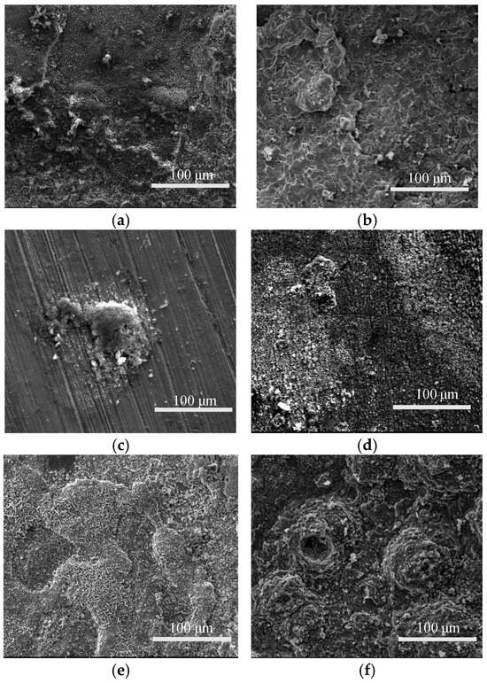
Figure 4.
Microscopic corrosion morphology of P110SS at different H2S partial pressure and temperature (a) 60 °C, 0.1 MPa H2S (b) 160 °C, 0.1 MPa H2S (c) 60 °C, 0.5 MPa H2S (d) 100 °C, 0.5 MPa H2S (e) 140 °C, 0.5 MPa H2S (f) 180 °C, 0.5 MPa H2S.
3.4. Corrosion Product Composition
Figure 5 presents the XRD spectra of the surface corrosion products of P110SS under different temperatures and H2S partial pressures. The experimental results indicate that when the H2S partial pressure dominates, no FeCO3 is present in the corrosion products, which are entirely composed of sulfur and iron compounds. Under constant H2S partial pressure, at 60 °C, the corrosion products are primarily composed of Mackinawite, indicating that lower temperatures favor the crystallization and growth of Mackinawite. Additionally, some peaks corresponding to the base iron are observed, suggesting that at 60 °C, corrosion is not severe, and the corrosion products do not completely cover the metal substrate. At 100 °C, in addition to Mackinawite, pyrrhotite (Fe1−XS) is also detected, indicating that Mackinawite becomes unstable at higher temperatures and gradually transforms into pyrrhotite with the increase in temperature. At 140 °C, Mackinawite is no longer detected, suggesting that corrosion intensifies further, causing all Mackinawite in the corrosion products to transform into pyrrhotite. At 180 °C, the corrosion products are entirely pyrrhotite, indicating that with further temperature increase, no transformation of the corrosion products occurs. This suggests that pyrrhotite formed under these conditions is stable and no longer undergoes a phase transition. Under a constant H2S partial pressure, when the H2S pressure increases from 0.1 MPa to 0.5 MPa at 60 °C, there is no significant change in the type of corrosion products, which remain predominantly Mackinawite.
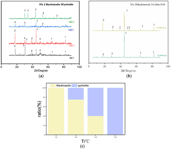
Figure 5.
(a) XRD patterns of corrosion products of P110SS at different temperatures; (b) XRD patterns of corrosion products of P110SS at different H2S partial pressures; (c) Variation in Composition of Corrosion Products of P110SS at Different Temperatures.
3.5. Microscopic Morphology of Corrosion Product Cross-Sections
Figure 6 shows the cross-sectional view of the sample after corrosion at 140 °C. At this temperature, pitting corrosion is observed. From the cross-sectional image, the corrosion product layer is divided into two distinct parts. The corrosion products covering the surface mainly consist of sulfur (S) and iron (Fe). The elemental distribution in the pitting corrosion sites includes S, Fe, and chlorine (Cl), with Cl primarily concentrated at the pit bottom. This indicates the enrichment of Cl at the pit base, suggesting the occurrence of a self-catalytic effect, where the pH value decreases, acidifying the environment inside the pit. As a result, local anodic dissolution occurs, leading to the formation of pitting corrosion [30].
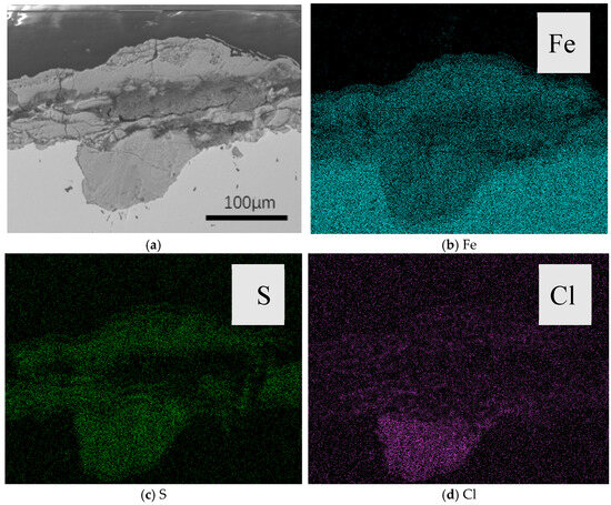
Figure 6.
(a) Cross-sectional view of the sample after corrosion at 140 °C; (b) Distribution of Fe Element Along the Cross-Section; (c) Distribution of S Element Along the Cross-Section; (d) Distribution of Cl Element Along the Cross-Section.
3.6. Ion Selectivity of Corrosion Products
Figure 7 illustrates the ion selectivity of the corrosion product film of P110SS under different temperatures at the same H2S partial pressure, as well as the ion selectivity of the corrosion products at the same temperature but different H2S partial pressures. Generally, the corrosion product films in hydrogen sulfide environments for low-alloy steels exhibit ion selectivity, which can influence the corrosion rate and alter the corrosion process. The experimental results show that, under the same H2S partial pressure, the corrosion product curves at 60 °C and 100 °C are negative, while those at 140 °C and 180 °C are positive. A negative slope indicates cation selectivity, while a positive slope indicates anion selectivity, with a steeper slope indicating stronger selectivity. It can be concluded that Mackinawite exhibits strong cation selectivity, while pyrrhotite shows stronger anion selectivity [31]. At 60 °C, when the H2S partial pressure increases from 0.1 MPa to 0.5 MPa, the ion selectivity remains cation-selective. At 160 °C, as the H2S partial pressure increases from 0.1 MPa to 0.5 MPa, the ion selectivity shifts to anion-selective. At the same temperature, varying the H2S partial pressure within a certain range has little effect on the ion selectivity of the corrosion product film.
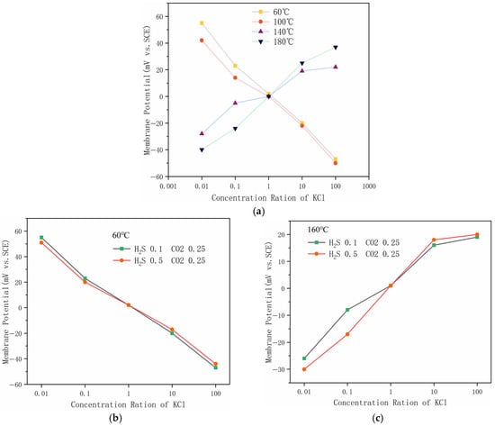
Figure 7.
Ion selectivity of corrosion products (a) Ion selectivity of the corrosion product film at different temperatures; (b) ion selectivity of the corrosion product film at 60 °C; (c) ion selectivity of the corrosion product film at 160 °C.
4. Discussion
Under the same temperature conditions, varying the H2S partial pressure within a certain range does not significantly affect the corrosion rate, likely because the corrosion products remain unchanged. From the membrane potential experiment, altering the H2S partial pressure does not affect the ion selectivity of the corrosion product film. At 160 °C, when the H2S partial pressure is increased to 0.5 MPa, a decrease in the corrosion rate is observed. Based on the microscopic morphology of the corrosion products, this could be due to the corrosion products becoming more compact with the increase in H2S partial pressure, which may help to slow down the corrosion rate to some extent. Under constant H2S partial pressure, increasing the temperature generally leads to an increase in the corrosion rate. A significant rise in the corrosion rate is observed between 100 °C and 140 °C. From the composition of the corrosion products and their ion selectivity, this increase in corrosion rate may be due to the transformation of the corrosion product type from Mackinawite to pyrrhotite between 100 °C and 140 °C. Since Mackinawite exhibits cation selectivity, it can effectively prevent anions from passing through the corrosion product film to reach the metal substrate, thereby slowing the corrosion process. Once the transformation to pyrrhotite occurs, the corrosion rate increases sharply, possibly because pyrrhotite exhibits anion selectivity, allowing anions such as Cl− to pass through the corrosion product film and accumulate on the metal substrate, leading to the development of a self-catalytic acidification effect. This acidifies the localized region of the substrate, resulting in pitting corrosion and a significant increase in the corrosion rate. Pyrrhotite exhibits anion selectivity. It may be that the atomic type on the (001) crystal plane changes from Fe to S, making the atoms exposed to the outermost surface become Fe, which attracts anions and causes the corrosion product to have anion selectivity [31].
5. Conclusions
- (1)
- At 60 °C, increasing the H2S partial pressure from 0.1 MPa to 0.5 MPa has no significant effect on the corrosion rate. At 160 °C, increasing the H2S partial pressure from 0.1 MPa to 0.5 MPa results in a decrease in the corrosion rate.
- (2)
- When the H2S partial pressure remains constant, the corrosion rate increases with temperature, following an overall S-shaped trend. A significant increase in the corrosion rate is observed between 100 °C and 140 °C. From 140 °C to 180 °C, pitting corrosion occurs.
- (3)
- The primary corrosion product is Mackinawite below 100 °C. Between 100 °C and 140 °C, it transitions from Mackinawite to pyrrhotite, and from 140 °C to 180 °C, the corrosion product remains pyrrhotite. The Mackinawite formed at lower temperatures exhibits cation selectivity, while the pyrrhotite formed at higher temperatures exhibits anion selectivity.
Author Contributions
Conceptualization, J.L. and H.Y.; methodology, L.Z.; validation, Y.L., K.X. and J.L.; formal analysis, J.T.; investigation, J.T.; resources, H.Y.; data curation, J.T.; writing—original draft preparation, J.T.; writing—review and editing, H.Y.; visualization, J.T.; supervision, J.L.; project administration, J.L.; funding acquisition, J.L. All authors have read and agreed to the published version of the manuscript.
Funding
This study received no external funding.
Institutional Review Board Statement
Not applicable.
Informed Consent Statement
Not applicable.
Data Availability Statement
All data was contained in the main text.
Conflicts of Interest
Authors Junan Lu, Lei Zha, Yong Liu, Kaiyun Xu were employed by the company Petrochina Tarim Oilfield Company. The remaining authors declare that the research was conducted in the absence of any commercial or financial relationships that could be construed as potential conflicts of interest.
References
- Zhao, J.; Ren, L.; Lin, C.; Lin, R.; Hu, D.; Wu, J.; Song, Y.; Shen, C.; Tang, D.; Jiang, H. A review of deep and ultra-deep shale gas fracturing in China: Status and directions. Renew. Sustain. Energy Rev. 2025, 209, 115111. [Google Scholar] [CrossRef]
- Sun, J.; Yang, J.; Bai, Y.; Lyu, K.; Liu, F. Research progress and development of deep and ultra-deep drilling fluid technology. Pet. Explor. Dev. 2024, 51, 1022–1034. [Google Scholar] [CrossRef]
- Zhu, L.; Luo, J.; Long, Y.; Li, L.; Xie, J. Failure analysis of S13Cr-110 telescopic tube used in an ultra-deep gas well. Eng. Fail. Anal. 2023, 146, 107099. [Google Scholar] [CrossRef]
- Chen, Z.; Sun, S.; Huang, H.; He, J.; Ouyang, Z.; Yu, S.; Li, X.; Fu, A.; Feng, Y. Corrosion behavior and failure mechanism of V150 drill pipe in HPHT and ultra-deep drilling process. Eng. Fail. Anal. 2024, 158, 107974. [Google Scholar] [CrossRef]
- Chen, Z.; Xu, M.; Hu, T.; Xue, G.; Chen, F.; Zhao, H.; Zhou, H.; Lei, Y.; Zhu, K. Effects of H2S content on the corrosion behavior of gas storage reservoir injection and production pipeline steel in CO2-H2S environment. Mater. Today Commun. 2024, 41, 110364. [Google Scholar] [CrossRef]
- Pu, L.; Xu, P.; Xu, M.; Song, J.; He, M. Lost circulation materials for deep and ultra-deep wells: A review. J. Pet. Sci. Eng. 2022, 214, 110404. [Google Scholar] [CrossRef]
- Yue, Y.; Yin, Z.; Li, S.; Zhang, Z.; Zhang, Q. Corrosion Behavior of Mild Steel in Various Environments Including CO2, H2S, and Their Combinations. Metals 2025, 15, 440. [Google Scholar] [CrossRef]
- Liao, K.; Qin, M.; Yang, N.; He, G.; Zhao, S.; Zhang, S. Corrosion main control factors and corrosion degree prediction charts in H2S and CO2 coexisting associated gas pipelines. Mater. Chem. Phys. 2022, 292, 126838. [Google Scholar] [CrossRef]
- Wang, Y.; Wang, B.; He, S.; Zhang, L.; Xing, X.; Li, H.; Lu, M. Unraveling the effect of H2S on the corrosion behavior of high strength sulfur-resistant steel in CO2/H2S/Cl− environments at ultra high temperature and high pressure. J. Nat. Gas Sci. Eng. 2022, 100, 104477. [Google Scholar] [CrossRef]
- Okonkwo, P.; Shakoor, R.; Benamor, A.; Amer Mohamed, A.M.; Al-Marri, M.J.F. Corrosion Behavior of API X100 Steel Material in a Hydrogen Sulfide Environment. Metals 2017, 7, 109. [Google Scholar] [CrossRef]
- Long, W.; Wang, X.; Hu, H.; Lu, W.; Liu, L.; Zhou, M.; Cao, S.; Chen, X. Primary Corrosion Cause of P110S Steel Tubing Corrosion Thinning in CO2–H2S Well and Its Remaining Life Prediction. Processes 2023, 11, 333. [Google Scholar] [CrossRef]
- Wang, J.-B.; Xiao, G.-C.; Zhao, W.; Zhang, B.R.; Rao, W.F. Microstructure and Corrosion Resistance to H2S in the Welded Joints of X80 Pipeline Steel. Metals 2019, 9, 1325. [Google Scholar] [CrossRef]
- Zhao, X.; Huang, W.; Li, G.; Feng, Y.; Zhang, J. Effect of CO2/H2S and Applied Stress on Corrosion Behavior of 15Cr Tubing in Oil Field Environment. Metals 2020, 10, 409. [Google Scholar] [CrossRef]
- Huang, X.; Zhou, L.; Li, Y.; Du, Z.; Zhu, Q.; Han, Z. The synergistic effect of temperature, H2S/CO2 partial pressure and stress toward corrosion of X80 pipeline steel. Eng. Fail. Anal. 2023, 146, 107079. [Google Scholar] [CrossRef]
- Qin, M.; Liao, K.; He, G.; Zou, Q.; Zhao, S.; Zhang, S. Corrosion mechanism of X65 steel exposed to H2S/CO2 brine and H2S/CO2 vapor corrosion environments. J. Nat. Gas Sci. Eng. 2022, 106, 104774. [Google Scholar] [CrossRef]
- Wang, H.; Yu, C.; Gao, X.; Du, L.; Wang, H. Corrosion Behavior of Ferrite-Pearlite Steel Exposed to H2S/CO2 Environment. Int. J. Electrochem. Sci. 2020, 15, 6737–6747. [Google Scholar] [CrossRef]
- Yang, L.; Zhang, J.; Li, F.; Zeng, W.; Wang, B.; Guo, Y.; Wu, J.; Chen, Y.; Wang, M.; Lu, M. Study on corrosion behavior of P110S steel in CO2-H2S-saturated solution. Int. J. Electrochem. Sci. 2022, 17, 22018. [Google Scholar] [CrossRef]
- Liu, Z.; Gao, X.; Du, L.; Li, J.; Li, P.; Yu, C.; Misra, R.D.K.; Wang, Y. Comparison of corrosion behaviour of low-alloy pipeline steel exposed to H2S/CO2-saturated brine and vapour-saturated H2S/CO2 environments. Electrochim. Acta 2017, 232, 528–541. [Google Scholar] [CrossRef]
- Wen, X.; Bai, P.; Luo, B.; Zheng, S.; Chen, C. Review of recent progress in the study of corrosion products of steels in a hydrogen sulphide environment. Corros. Sci. 2018, 139, 124–140. [Google Scholar] [CrossRef]
- da Silva, S.C.; de Souza, E.A.; Pessu, F.; Hua, Y.; Barker, R.; Neville, A.; Gomes, J.A.D.C.P. Cracking mechanism in API 5L X65 steel in a CO2-saturated environment. Eng. Fail. Anal. 2019, 99, 273–291. [Google Scholar] [CrossRef]
- Shi, F.X.; Zhang, L.; Yang, J.W.; Lu, M.; Ding, J.; Li, H. Polymorphous FeS corrosion products of pipeline steel under highly sour conditions. Corros. Sci. 2016, 102, 103–113. [Google Scholar] [CrossRef]
- Iglesias, N.; Díaz, E. Influence of H2S and CO2 Partial Pressures and Temperature on the Corrosion of Superduplex S32750 Stainless Steel. Corros. Mater. Degrad. 2025, 6, 20. [Google Scholar] [CrossRef]
- Nimmervoll, M.; Mori, G.; Bucher, E.; Schmid, A.; Haubner, R. Corrosion of N10276 in a H2S, HCl, and CO2 Containing Atmosphere at 480 °C and 680 °C. Metals 2021, 11, 1817. [Google Scholar] [CrossRef]
- Zhao, M.; Zhao, Z.; Xie, J.; Li, X.; Song, W.; Zhou, J.; He, Q. The Synergistic Influence of Trace Impurities and Temperature on the Corrosion Behavior of Tubing in Supercritical CO2 Environment. Coatings 2025, 15, 944. [Google Scholar] [CrossRef]
- Sun, J.; Sun, C.; Lin, X.; Cheng, X.; Liu, H. Effect of Chromium on Corrosion Behavior of P110 Steels in CO2-H2S Environment with High Pressure and High Temperature. Materials 2016, 9, 200. [Google Scholar] [CrossRef] [PubMed]
- Gani, M.S.; Ghorbani, M.; Afshar, A.; Rahmaniyan, M. Modeling of carbon dioxide corrosion of steel with iron carbonate precipitation. Corros. Eng. Sci. Technol. 2009, 44, 128–136. [Google Scholar] [CrossRef]
- Nesic, S.; Lee, K.L.J. A mechanistic model for carbon dioxide corrosion of mild steel in the presence of protective iron carbonate films—Part 3: Film growth model. Corros. Sci. 2000, 42, 1353–1371. [Google Scholar]
- Miyuki, H.; Yamashita, M.; Fujiwara, M.; Misawa, T. Ion selective properties of rust membranes and protective effect of stable rust layer formed on weathering steel. Zair. Kankyo 1998, 47, 186–192. [Google Scholar] [CrossRef]
- Sun, Q.; Chen, C.; Zhao, X.; Chi, H.; He, Y.; Li, Y.; Qi, Y.; Yu, H. Ion-selectivity of iron sulfides and their effect on H2S corrosion. Corros. Sci. 2019, 158, 108085. [Google Scholar] [CrossRef]
- Li, T.; Wu, J.; Frankel, G.S. Localized corrosion: Passive film breakdown vs. Pit growth stability, Part VI: Pit dissolution kinetics of different alloys and a model for pitting and repassivation potentials. Corros. Sci. 2021, 182, 109277. [Google Scholar] [CrossRef]
- Liu, J.; Chen, C.; Lei, B.; Zhu, X.; Wan, H.; Yu, H.; Jia, X. Mechanism of transformation of ion-selectivity of pyrrhotite by hypervalent anion (SO42−) and its effect on corrosion behavior. Surf. Interfaces 2025, 62, 106200. [Google Scholar] [CrossRef]
Disclaimer/Publisher’s Note: The statements, opinions and data contained in all publications are solely those of the individual author(s) and contributor(s) and not of MDPI and/or the editor(s). MDPI and/or the editor(s) disclaim responsibility for any injury to people or property resulting from any ideas, methods, instructions or products referred to in the content. |
© 2025 by the authors. Licensee MDPI, Basel, Switzerland. This article is an open access article distributed under the terms and conditions of the Creative Commons Attribution (CC BY) license (https://creativecommons.org/licenses/by/4.0/).