Abstract
The use of molybdenum-based alloys as materials for components operating under high temperatures and significant mechanical loads is widely recognized due to their excellent mechanical properties. However, their low high-temperature resistance remains a critical limitation, which can be effectively mitigated by applying protective coatings. In this study, we investigate the influence of a two-step coating process on the properties and performance of the TZM molybdenum alloy. In the first step, pack cementation was performed. Simultaneous surface saturation with aluminum and silicon, a process known as aluminosiliconizing, was conducted at 1000 °C for 6 h. The saturating mixture comprised powders of aluminum, silicon, aluminum oxide, and ammonium chloride. The second step involved the application of a pre-ceramic coating based on polyhydrosiloxane modified with silicon and boron. This treatment effectively eliminated pores and cracks within the coating. Thermodynamic calculations were carried out to evaluate the likelihood of aluminizing and siliconizing reactions under the applied conditions. Aluminosiliconizing of the TZM alloy resulted in the formation of a protective layer 20–30 µm thick. The multiphase structure of this layer included intermetallics (Al63Mo37, MoAl3), nitrides (Mo2N, AlN, Si3N4), oxide (Al2O3), and a solid solution α-Mo(Al). Subsequent treatment with silicon- and boron-modified polyhydrosiloxane led to the development of a thicker surface layer, 130–160 µm in thickness, composed of crystalline Si, amorphous SiO2, and likely amorphous boron. A transitional oxide layer ((Al,Si)2O3) 5–7 µm thick was also observed. The resulting coating demonstrated excellent structural integrity and chemical inertness in an argon atmosphere at temperatures up to 1100 °C. High-temperature stability at 800 °C was observed for both coating types: aluminosiliconizing, and aluminosiliconizing followed by the pre-ceramic coating. Moreover, additional oxide layers of SiO2 and B2O3 formed on the two-step coated TZM alloy during heating at 800 °C for 24 h. These layers acted as an effective barrier, preventing the evaporation of the substrate material.
1. Introduction
Both scientific and industrial communities demonstrate a growing interest in improving the performance characteristics of materials and components operating under conditions of elevated temperatures and mechanical loads. Furthermore, attention is increasingly directed toward meeting economic and environmental requirements. Refractory materials (among them molybdenum, niobium, tantalum, tungsten) and their alloys have repeatedly proven to be effective in maintaining high hardness and strength at elevated temperatures [1,2].
Nevertheless, their relatively low resistance (400–800 °C) to high-temperature corrosion imposes considerable limitations on their practical applications [3].
There are two distinct approaches to addressing this issue proposed by contemporary research: alloying and applying protective coatings to the refractory base material [3,4].
One of the approaches proposed in contemporary research to address this challenge is the application of protective coatings to refractory substrates. The enhancement of the performance characteristics of materials operating under high-temperature conditions is achieved by modifying the chemical composition of the refractory surface, which can be technologically implemented through a single method or a combination of methods. It should also be emphasized that existing technologies enable the deposition of either a single chemical element [1,5,6] or multiple elements [1,7,8,9,10].
Single-component surface saturation of molybdenum alloys with silicon by pack cementation has been proposed in [5,6,11]. In [6], the optimal ratio of the components of the siliconizing mixture for Mo–1B (wt.%) and the process parameters (temperature and time) were analyzed in relation to coating thickness and oxidation resistance at elevated temperatures. The authors concluded that siliconizing the molybdenum alloy at 1100 °C for 48 h leads to the formation of a MoSi2 coating. The samples exhibited excellent oxidation resistance at 1400 °C for 40 h, primarily due to the presence of a MoB layer between the MoSi2 coating and the substrate. In [6], the influence of the activator content during pack cementation was also analyzed, specifically the effect of NaF concentration (1%–15% wt.) on the protective coating thickness. However, another study [12] reported that, during pack boron-siliconizing, chlorine-containing activators provide greater advantages compared to fluorine-containing ones.
In [13], it was shown that, after single-component siliconizing a TZM alloy in chlorine-containing medium (NH4Cl), a multilayer coating forms that consists of phases based on MoSi2, Mo5Si3C, Mo5Si3, and Si2N2O. Total thickness of the coating was 50–63 µm. The coating demonstrated excellent oxidation resistance at 800 °C for 48 h.
Siliconizing of a three-phase molybdenum alloy (Mo–14.2Si–9.6B (at.%)) by pack cementation at 900 °C for 48 h resulted in the formation of a 10 µm MoSi2 layer [5]. During high-temperature oxidation, the coating transformed into the Mo5Si3 phase, thereby providing oxidation protection at elevated temperatures. The study analyzed the oxidation mechanism at 1000 and 1200 °C for 25, 50, and 100 h. The significant oxidation resistance of the Mo5Si3 layer was attributed to boron diffusion from the alloy matrix, acting as an effective diffusion barrier for silicon [5]. This mechanism was confirmed in [13]. As a result, molybdenum alloys subjected to pack cementation with silicon and boron demonstrate stable performance at temperatures up to 1700 °C.
In [14], the influence of the Si/B ratio in molybdenum alloys Mo–3Si–1B (wt%) [Mo–8.9Si–7.1B (at.%)] on the oxidation resistance was analyzed. High-temperature protection of the substrate was ensured by the formation of a continuous boron–siliconizing layer on the surface, while the stability and integrity of the coating were guaranteed by the presence of a Mo5SiB2 diffusion barrier layer. A continuation of this research was presented in [9], which analyzed the oxidation resistance of Nb-based alloys (Nb–15Si–24Ti–4Cr–2Al–2Hf (at.%)) at elevated temperatures. The process was carried out in two successive stages: first, a molybdenum layer was deposited, followed by simultaneous silicon and boron deposition by pack cementation using CrB2 as the boron source. Pack cementation was performed at 1000 °C for 25 h in an argon atmosphere. After complex pack cementation with silicon, boron, and molybdenum, a multilayer coating was formed on the niobium alloy, consisting of an outer aluminoboron–siliconizing layer, a middle Nb5SiB2 layer, and an inner NbSi2 layer. It was noted that the outer aluminoboron–siliconizing layer, formed upon subsequent heating, suppressed rapid oxidation and limited oxygen diffusion, thereby acting as an effective protective layer [9].
Other studies [7] recommended improving the oxidation resistance and service life of Mo–9Si–8B (at.%) alloys through complex saturation with two chemical elements (silicon and boron). Subsequent scale-resistance tests confirmed the effectiveness of the combined coating under high-temperature and cyclic thermal loading. The possibility of enabling tungsten-based products to retain their shape, size, and mass under high temperatures and loads was considered in [8]. A two-stage deposition of a Mo–Si–B protective coating was applied onto a tungsten substrate. The authors experimentally demonstrated not only the potential of Mo–Si–B coatings, but also certain advantages of this composition compared to W–Si–B or WSi2 coatings [8].
In [15], a two-layer system was deposited onto Mo–9Si–8B alloys using magnetron sputtering, consisting of an intermediate Mo–Si layer and a top silicon protective layer. The intermediate layer ensured adhesion between the top layer and the substrate by providing thermodynamic compatibility between the alloy and silicon.
In [9], a technology was proposed in which pack cementation of Mo–Si–B alloys results in the formation of an aluminoboron–siliconizing surface layer and internal self-healing diffusion barriers, thereby enhancing oxidation resistance.
In [1], the properties of single-component aluminum coatings and two-component boron–siliconizing coatings obtained by pack cementation of molybdenum substrates were analyzed.
A comparative analysis of existing methods and parameters for applying protective coatings to molybdenum alloys was conducted in [4]. The authors compared literature data regarding the influence of carburizer content on the composition and properties of molybdenum and the TZM-based alloy. Several components of the mixtures were compared: 7Si–87Al2O3–6NH4Cl; 7Al–7Si–10NH4F–76Al2O3; 12Si–3B–6Al–2Y2O; 3–5NaF–72Al2O3; 70Al2O3–20Al–10NH4Cl; 25Si–5NaF–70Al2O3; 81Al2O3–7Si–7Al–5NH4F.
In the work [4], the authors addressed several key issues: the growth mechanism, oxidation behavior, and formation mechanism of coatings using the halide-activated pack cementation (HAPC) method. The process conditions and properties of the resulting coatings were reported. The main advantages of HAPC noted by the authors include the absence of substrate shape limitations, compositional homogeneity, and good adhesion to the substrate [4].
The possibility of void formation in protective silicide and aluminosilicide coatings on the TZM alloy was also discussed in [16]. The slurry cementation technology proposed in this study (multiple immersions in the slurry mixture) was carried out at 1000 °C for various durations using different slurry masses. It was demonstrated that the slurry mass significantly affected the morphology and growth kinetics of silicide-aluminide coatings. The authors noted that insufficient slurry mass leads to a deficiency of alloying elements during prolonged processes, which reduces the growth rate and can result in void formation within the silicide-aluminide coating structure.
The negative effects of microcracks [4], and voids [16] formed during the deposition of diffusion protective coatings can be mitigated by improving the technology with an additional operation—application and pyrolysis of a ceramic coating.
Ceramic coatings derived from preceramic polymers have demonstrated high efficiency in protecting steel materials from oxidation at elevated temperatures [17]. Due to their viscous consistency or solubility in organic solvents, precursors such as polysiloxanes, polycarbosilanes, or polysilazanes can be applied by various methods, including brushing, dipping, spin-coating, or spraying [18]. After application, the samples are subjected to drying and heat treatment at moderate temperatures (100–400 °C) in air, during which solvent residues are removed and partial crosslinking occurs, forming a solid layer. In the final stage, pyrolysis is carried out at 700–1400 °C in an inert atmosphere (N2 or Ar), leading to the removal of organic components and transformation of the polymer into a ceramic matrix enriched with Si–O–N(–C) structures.
In [19,20], the thermo-oxidative behavior of coatings based on perhydropolysilazane (PHPS), applied by dip-coating onto Mo–Si–B alloys, was studied. It was found that during heat treatment, the polymer transforms into a ceramic phase, accompanied by internal shrinkage of the coating, which can lead to porosity and cracking. However, these drawbacks can be mitigated by incorporating dispersed fillers into the polymer matrix [21]. It was shown in [20] that the addition of components such as Si, B, SiB6, or Mo5SiB2 improves the cyclic oxidation resistance of Si–O–N coatings, as they promote the formation of a dense protective borosilicate glassy layer on the surface under high-temperature exposure.
In the work [22], coatings for the oxidation protection of Mo–Si–B alloys based on PHPS precursor filled with Si and B powders were investigated. After polymer pyrolysis into ceramic, a uniform distribution of the fillers in the SiO2/SiNO matrix was achieved. It was reported that the best protection at 800–1100 °C was provided by the composites (10B+35Si) and (15B+25Si), due to the high content of the amorphous SiNO phase formed after pyrolysis in nitrogen at 1000 °C.
However, such coatings do not always form fully dense layers, and their adhesion to the metallic substrate is typically achieved via mechanical interlocking, requiring careful surface preparation [20]. In the case of the TZM alloy, the significant difference in coefficients of thermal expansion between the metallic substrate and the glassy SiO2 layer can lead to thermal stresses and, consequently, limited adhesion of the preceramic coating.
Thus, the aim of this work is to develop an innovative method for surface modification of a molybdenum alloy. The main outcomes demonstrating the potential of the proposed method are analyzed through thermodynamic calculations, investigations of the macro- and microstructure, and the phase and chemical composition of the protective coating on the refractory alloy after pack cementation with aluminum and silicon, as well as after the two-step treatment: aluminosiliconizing followed by the application of a pre-ceramic coating based on polyhydrosiloxane modified with silicon and boron. The effect of the proposed treatments on the thermal and corrosion resistance of the alloy is also evaluated.
2. Materials and Methods
The industrial molybdenum alloy TZM of the following composition, % wt.: Mo + 0.5Ti + 0.08Zr + 0.02C [23], was used as the material to be processed. The alloy was produced under industrial conditions at the plant.
The coating process was carried out in two stages.
At the first stage, complex aluminosiliconizing was performed using the pack cementation method. The samples were placed in a container together with the powder saturating mixture, which consisted of (wt%.): 10 Al, 10 Si, 75 Al2O3, and 5 NH4Cl. The process was conducted at 1000 °C for 6 h in an argon atmosphere. Subsequently, the container with the samples was cooled under argon.
At the second stage, a coating was applied by a dip-coating process with a solution based on polyhydridosilazane (PHPS NN 12020, MERCK KGaA, PM-PFM-T 64293, durXtreme GmbH, Darmstadt, Germany) modified with silicon and boron particles. The following ratio of components (wt.%) was used: 65% PHPS + 34% crystalline silicon + 1% amorphous boron. After immersion, the samples were dried for one hour at 100 °C in air, followed by pyrolysis in a nitrogen atmosphere at 800 °C for one hour. Heating and cooling rates were xy K/min and YZ K/min, respectively.
The following powders were used for coating deposition: silicon (<160 μm), aluminum (<250 μm), and amorphous boron (10 μm).
The phase equilibrium of the most probably phases to be present after heat treatment was evaluated at a constant pressure of 102 Pa within the temperature range of 300–1200 °C. Calculations were performed for systems containing silicon and aluminum (saturating elements), molybdenum (the main component of the TZM alloy), and chlorine (a halogen present in the activator). The equilibrium composition of the multiphase system was determined using a method based on the second law of thermodynamics [24]. The calculations were performed with the “Astra. 4″ software package, employing a thermodynamic database that enables the determination of the composition of a closed system in a state of maximum entropy (Formula (1)).
where i, k, j are indices that belong to condensed phases, gases, and solution components; n—number of moles; x—concentration of substances; p—partial pressure.
The structure and elemental composition of the samples were studied on sample’s cross-sections. The preparation of the sections was carried out by sequential grinding and polishing using standard procedures with Struers equipment and consumables. The chemical composition and microstructure of the coatings obtained by aluminosiliconizing using the pack cementation method were investigated using a Carl Zeiss SIGMA 300 scanning electron microscope (Carl Zeiss AG, Oberkochen, Germany) in backscattered electron mode (phase contrast) at an accelerating voltage of 5 kV. The elemental composition of the coatings after aluminosiliconizing was determined using an Oxford Instruments X-MaxN energy-dispersive detector (Oxford Instruments plc, Abingdon, UK) and INCA 5.05 software. The elemental distribution in the coating and substrate was measured by stepwise scanning of the sample perpendicular to the cross-section surface. SEM investigations were carried out at positions along the coating growth direction with a step size of 1–2 μm and in zones located at various distances from the surface.
The chemical composition and microstructure of coatings obtained after two-stage treatment (aluminosiliconizing followed by the application of a pre-ceramic coating) were examined using a CamScan S4 scanning electron microscope (Obducat CamScan Ltd., Cambridge, UK) in backscattered electron mode (phase contrast) at an accelerating voltage of 20 kV. An Oxford Link Pentafet 5518 EDS energy-dispersive detector (Oxford Instruments, Abingdon, UK) and INCA 4.05 software were used. Unfortunately, the use of this microscope does not allow for the determination of light elements, specifically nitrogen.
The calculation errors for the elements based on the spectrum vary depending on the location, the time of spectrum acquisition, and the specific element, ranging from 0.15% to 0.85%.
X-ray diffraction (XRD) analysis was conducted using a Rigaku Ultima IV diffractometer with monochromatic CuKα radiation (λKα = 0.154184 nm). Diffraction patterns were processed and lattice parameters of the formed phases were determined by full-profile Rietveld refinement using the PowderCell 2.4 software package. Phase identification was performed by comparing the experimental diffraction patterns with reference data from the ICDD PDF-2 database.
Differential scanning calorimetry (DSC) was conducted in the temperature range from room temperature to 1200 °C under a flow of high-purity argon using a Linseis STA PT1600 TG-DSC/DTA instrument (Linseis Messgeräte GmbH, Selb, Germany) at a heating rate of 20 K/min with an isothermal hold of 1 h.
Cyclic oxidation resistance tests were performed in a muffle furnace LH 15/14 (Nabertherm GmbH, Lilienthal, Germany). Oxidation resistance was evaluated by measuring the mass change in the samples before and after oxidation at 800 °C for 1–24 h in air. Sample weighing was performed using NewClassic MF ML204/01 analytical balances (Mettler Toledo, Greifensee, Switzerland) with a maximum measurement error of no more than 0.0001 g. At least five parallel tests were carried out during the experiment. The average value was calculated, and the error of the obtained results did not exceed 5%–10%. Metallographic examinations of the oxidized samples were performed using a KERN OBN-135T241 optical microscope (KERN & SOHN GmbH, Balingen, Germany) after etching the samples in a 3% solution of nitric acid in ethanol.
3. Results
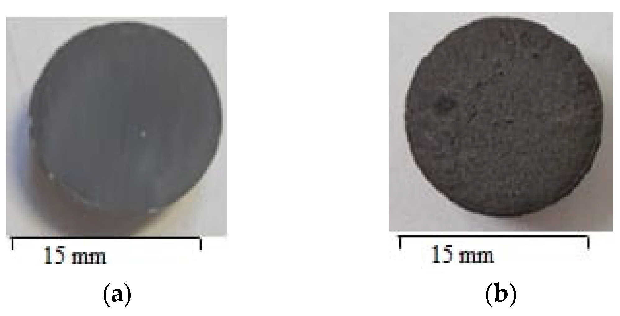
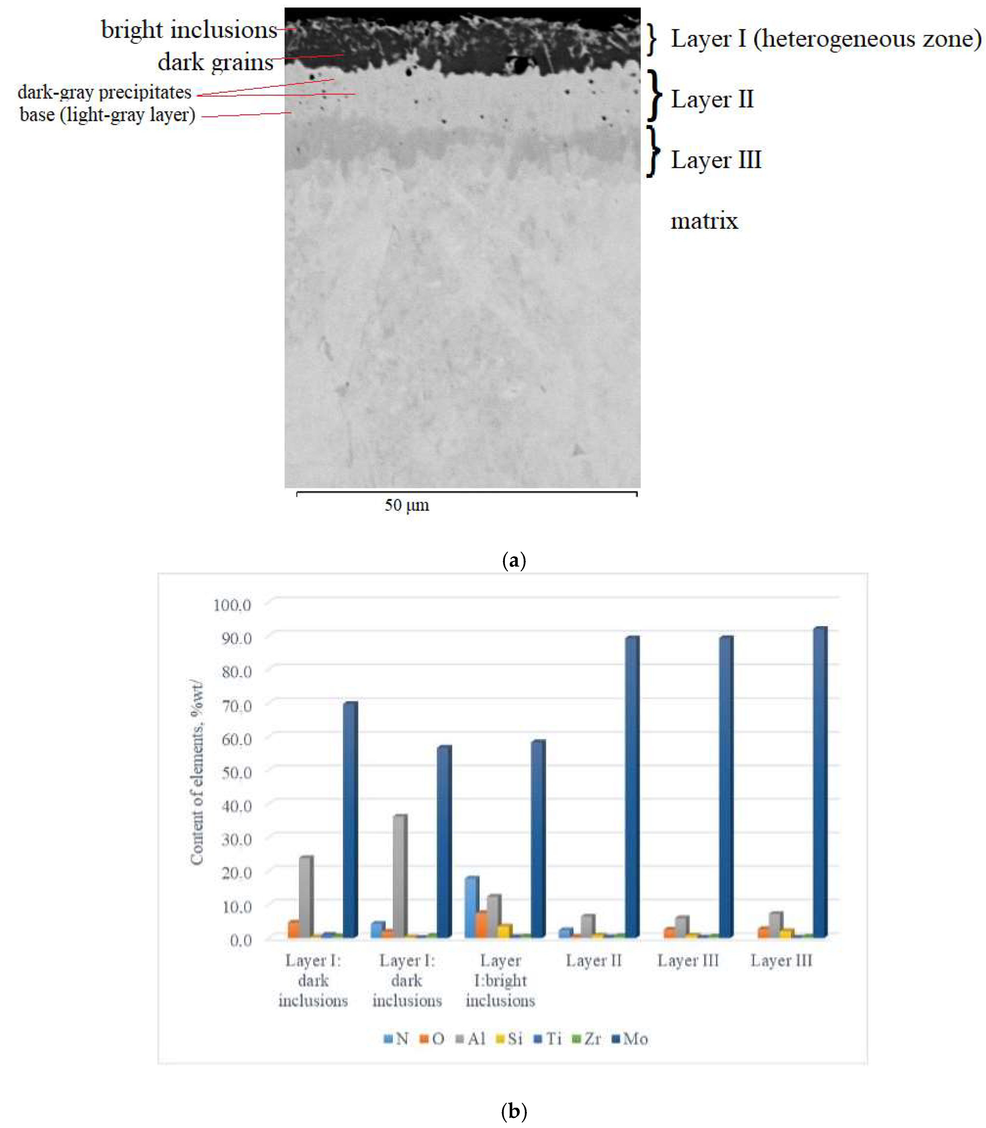
Visually, the coating obtained by complex aluminosiliconizing of the TZM molybdenum alloy via pack cementation was uniformly distributed across the cross-section of the samples, exhibiting a smooth gray surface without visible chipping or delamination (Figure 1a). Microstructurally, the coating possesses a multilayer architecture (Figure 2a), consisting of four zones with clearly defined interfaces. According to metallographic and micro–X-ray spectral analyses (Figure 2b), distinct zones within the coating were identified based on contrast differences and the presence of several phase constituents.
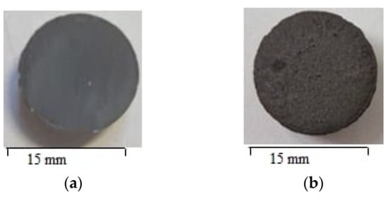
Figure 1.
Surface morphology of TZM alloy coatings obtained by (a) complex aluminosiliconizing and (b) aluminosiliconizing followed by a preceramic polyhydridosilazane-based coating modified with Si and B.
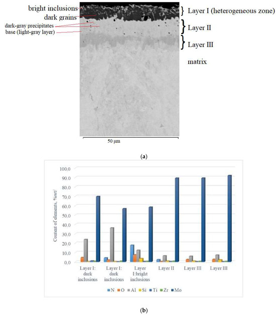
Figure 2.
Cross-sectional microstructure (a) and distribution of chemical elements (b) of the multilayer coating on TZM alloy after complex aluminosiliconizing.
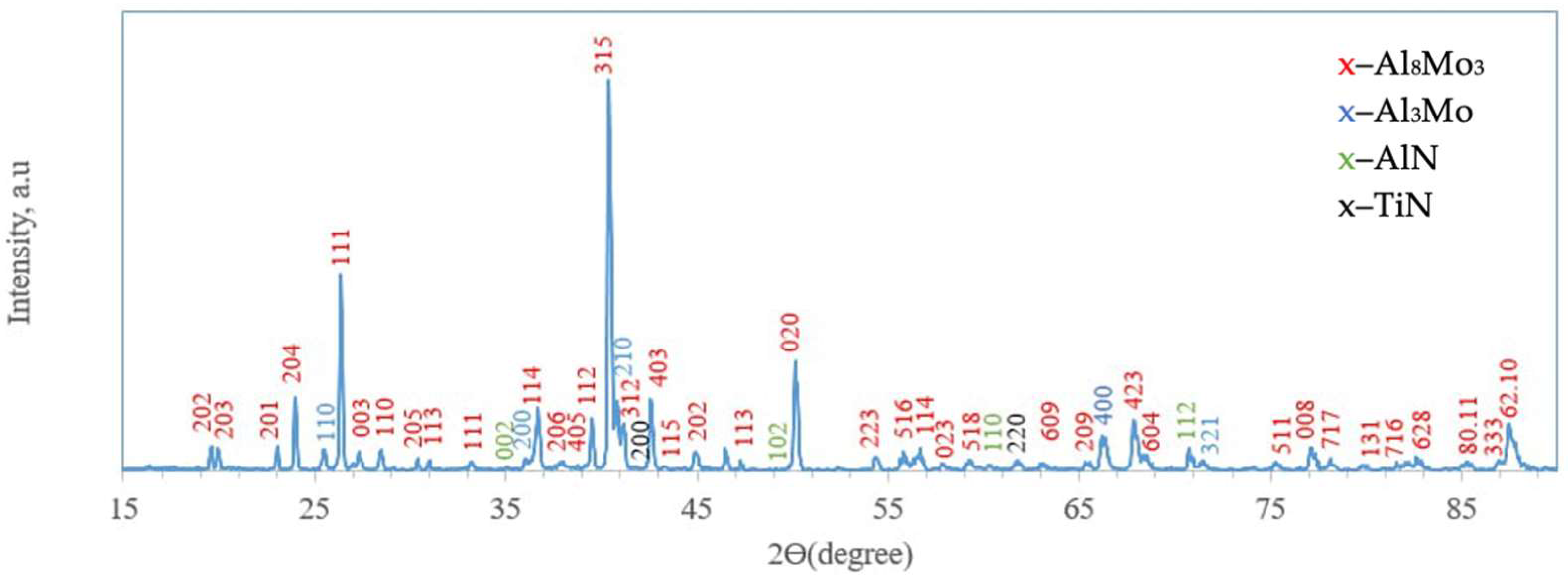
On the surface, a 5–7 µm thick layer (layer I) with a heterogeneous structure was formed. The layer is primarily composed of dark gray, nearly black grains surrounded by light, almost white inclusions. X-ray diffraction analysis of the coating surface (Figure 3) revealed the presence of peaks corresponding to molybdenum aluminides Al8Mo3 (75.57 wt%; lattice parameters: a = 9.207 Å, b = 3.632 Å, c = 14.862 Å) and Al3Mo (17.86 wt%; lattice parameter: a = 4.932 Å), as well as nitrides AlN (3.31 wt%; lattice parameters: a = 3.106 Å, c = 4.975 Å) and TiN (3.26 wt%; lattice parameter: a = 4.244 Å The chemical composition of the coatings was interpreted using the Al–Mo, Al–N, Mo–N, and Mo–Si phase diagrams [25] and correlated with the X-ray diffraction analysis data.
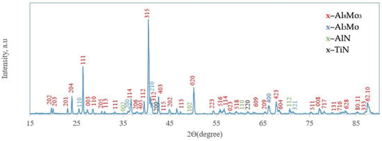
Figure 3.
X-ray diffractogram of the surface of TZM alloy after complex saturation aluminium and silicon (aluminosiliconizing); CuKα radiation, wavelength—0.1541841 nm.
The dark constituent of the surface layer consisted of the following elements (wt%): 69.76 Mo, 23.86 Al, 4.64 O, 0.26 Si, 0.93 Ti, and 0.55 Zr. Analysis of the coating along the cross-section from the surface inward shows that the elemental composition of the dark zone changes: the concentrations of molybdenum and oxygen decrease (to 56.73 wt.% Mo and 1.94 wt.% O), while aluminum content increases to 36.22 wt.%. Additionally, nitrogen was detected at 4.25 wt.%. This zone is composed of Al8Mo3- and Al3Mo-based phases, along with a small fraction of nitride phases, including AlN and TiN. Alloying elements such as Si and Zr are probably incorporated into solid solutions or partially form complex phases at grain boundaries in minor amounts. The likely source of oxygen and nitrogen is residual gases from the saturating mixtures used during pack cementation. Additional nitrogen incorporation may occur due to the elevated content of the activator NH4Cl (5 wt.%) in the saturating mixture [13].
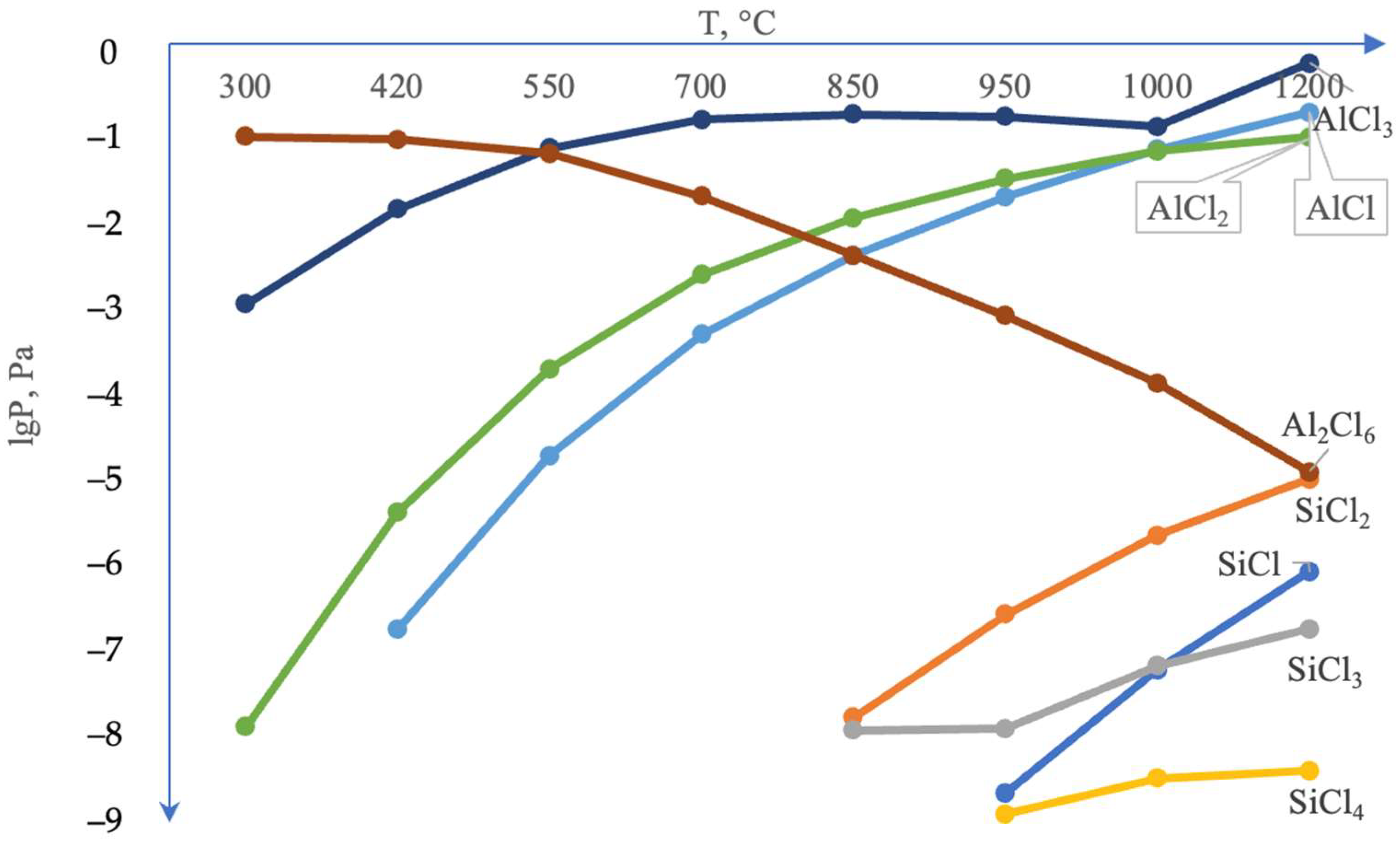
It is noteworthy that the silicon content in the coating’s surface layer is very low, not exceeding 0.21–0.26 wt.%. According to thermodynamic calculations under conditions of complex aluminosiliconizing treatment, aluminizing is more favorable than siliconizing. This is attributed to the higher partial pressure of aluminum chlorides compared to silicon chlorides (Figure 4).
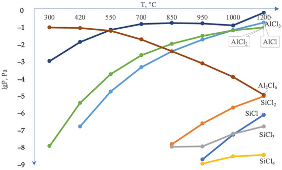
Figure 4.
Calculated equilibrium composition of the system Cl–Si–Al–Mo = 0.5–0.5–0.5–0.5 mol (gas phase).
The light inclusions in this layer are characterized by elevated contents of nitrogen (17.75 wt.%), oxygen (7.43 wt.%), and silicon (3.45 wt.%), whereas the amounts of aluminum and molybdenum decreased to 12.31 wt.% and 58.32 wt.%, respectively. This zone mainly consists of nitride phases based on Mo2N, AlN, and Si3N4, aluminum oxide (Al2O3), and a solid solution of aluminum in molybdenum (α–Mo(Al)). This zone did not form a continuous nitride layer, which is likely associated with an insufficient amount of nitrogen. The accumulation of silicon in this coating region is most likely associated with its high chemical affinity for nitrogen [26].
Beneath this layer, there is a light-gray layer with a thickness of 10–15 μm. Within the structure of this layer (Layer II), individual darker gray inclusions were observed, with sizes ranging from 1–3 μm (and in some cases up to 5–6 μm) (Figure 2a). In addition, isolated dark inclusions, which are likely pores, are observed across the cross-section of this layer.
The light-gray constituent of this layer consists of (in % wt.): 91.9–92.2 Mo, 5.9–6.9 Al, and 0.9–2.2 Si. The darker gray inclusions correspond to a phase region consisting of (in % wt.): 89.23 Mo, 6.41 Al, 2.34 N, and 0.39 O. The contents of Si, Ti, and Zr are minor, amounting to wt.%: 0.79, 0.26 and 0.59, respectively.
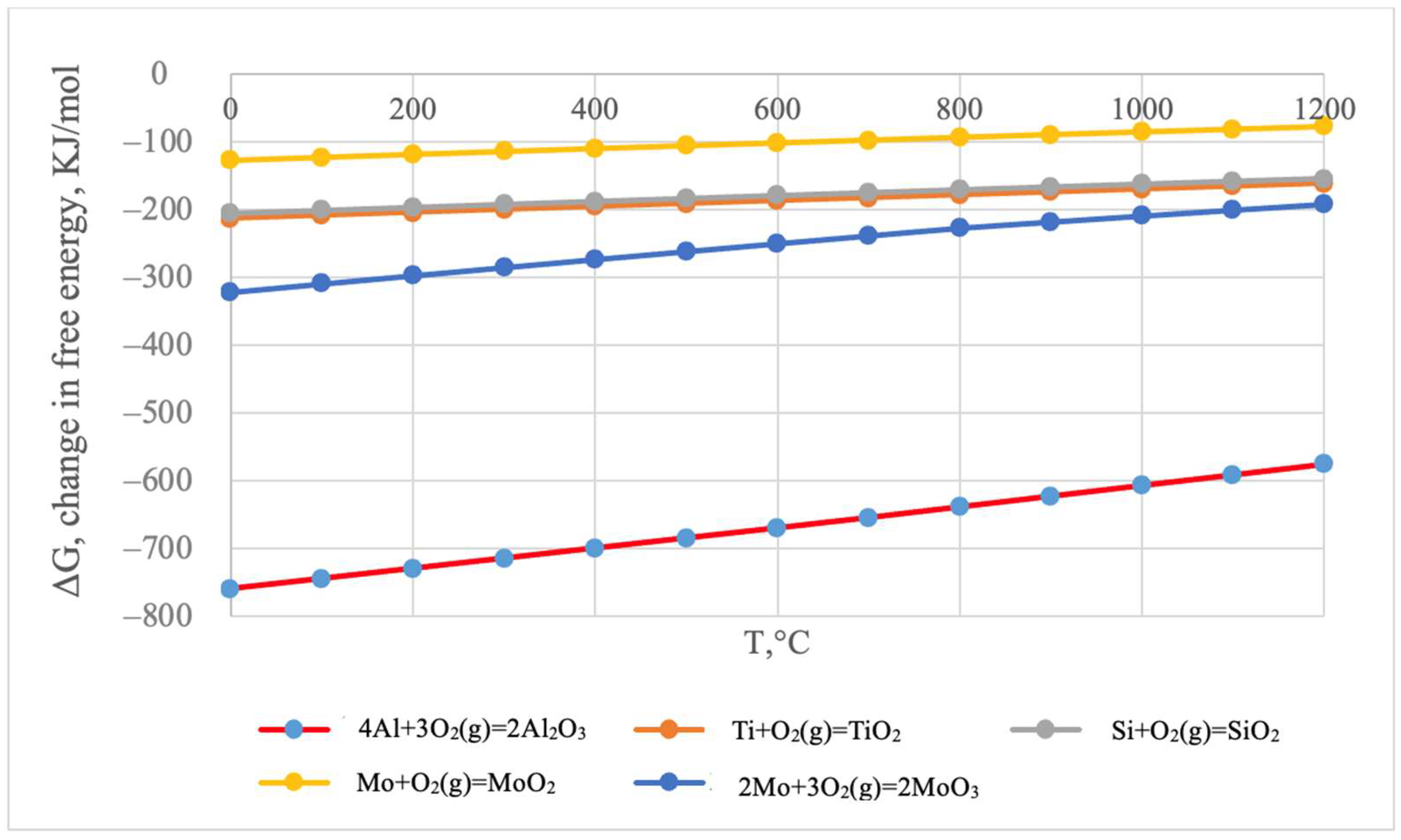
According to the thermodynamic calculations, the formation of aluminum oxides is the most thermodynamically probable (Figure 5).
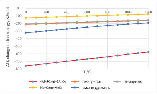
Figure 5.
Change in the Gibbs free energy of chemical reactions as a function of temperature.
A further 5–8 µm thick layer can be subdivided into two zones (Figure 2a): an initial dark-gray zone followed, toward the matrix, by a gray zone. No significant differences in chemical composition were observed between these sublayers. The aluminum content ranges from 5.93–7.2 wt.%, silicon from 0.76–2.07 wt.%, and molybdenum remains high at 89.31–92.03 wt.%. Additionally, localized oxygen inclusions are present, reaching up to 2.68 wt.%. The primary phase of this zone is a solid solution of aluminum and silicon in molybdenum (α-Mo(Al,Si)). Small oxygen inclusions may form dispersed oxide particles, mainly Al2O3. Silicon concentrations are insufficiently low to form separate silicide phases, but they can stabilize grain boundaries and contribute to increased hardness of the diffusion layer.
A limitation of coatings obtained via pack cementation is the formation of pores due to crystal lattice defects (vacancies) that arise during diffusion in the surface zone of the metal. The accumulation of excess vacancies leads to the formation of micropores [24]. These defects can be minimized by forming an additional protective layer that covers and heals through-pores. The use of preceramic polymer coatings to fill pores and defects is a promising approach to enhance the mechanical and functional properties of materials. This is possible due to their ability to penetrate microdefects and transform into a ceramic phase during pyrolysis [27].
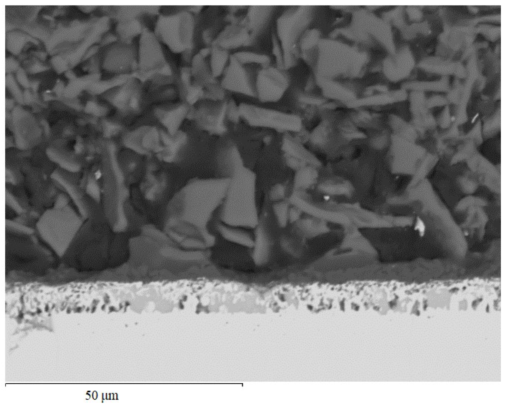
Applying a preceramic coating based on polyhydrosilazane modified with silicon and boron led to the formation of an additional layer on the surface of the coating after aluminosiliconizing obtained by pack cementation, consisting of two zones (Figure 6). The coating zone formed at the interface between the two types of coatings appears as a continuous dark-gray layer and serves as a transition zone between the reactive diffusion layer and the outer coating. The thickness of this layer is 5–7 µm. Its composition is 40.71 wt.% aluminum, 3.48 wt.% silicon, and 53.38 wt.% oxygen. This layer represents a silicon-doped aluminum oxide, (Al,Si)2O3. The oxygen source is likely the oxygen-containing fragments of the polyhydrosilazane precursor, which decomposed during pyrolysis at approximately 800 °C, releasing oxygen [25]. The released oxygen reacts with aluminum and silicon in the near-surface zone, promoting the formation of the oxide phase, which provides additional surface protection and stabilizes the structure of the transition layer. Moreover, the formation of nitrogen-containing compounds, such as Si2ON2, is also possible in the coatings [2,20].
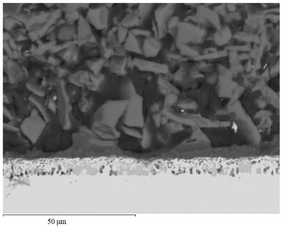
Figure 6.
Microstructure of the TZM alloy coating after two-step treatment: complex aluminosiliconizing (spotted layer in the middle) and deposition of a Si- and B-filled polyhydrosilazane preceramic layer (dark layer on top with a particular structure).
The top layer of the coating consists of discrete crystalline inclusions uniformly distributed across the surface. The morphology of these inclusions is diverse, with predominately plate-like, flake-like, and needle-like shapes arranged in a random spatial distribution. Particle sizes range from 2–5 µm (fine fragments) to 15–20 µm (individual large plates or aggregates). The thickness of this layer is 130–160 µm. It should be noted that the layer thickness depends on the viscosity of the polyhydrosilazane and the withdrawal speed of the samples from the disperse dip-coating system. The coating surface appears dark gray with a slight brownish tint, characteristic of amorphous boron, and exhibits moderate surface roughness, indicating heterogeneity of the microstructure after pyrolysis (Figure 1b).
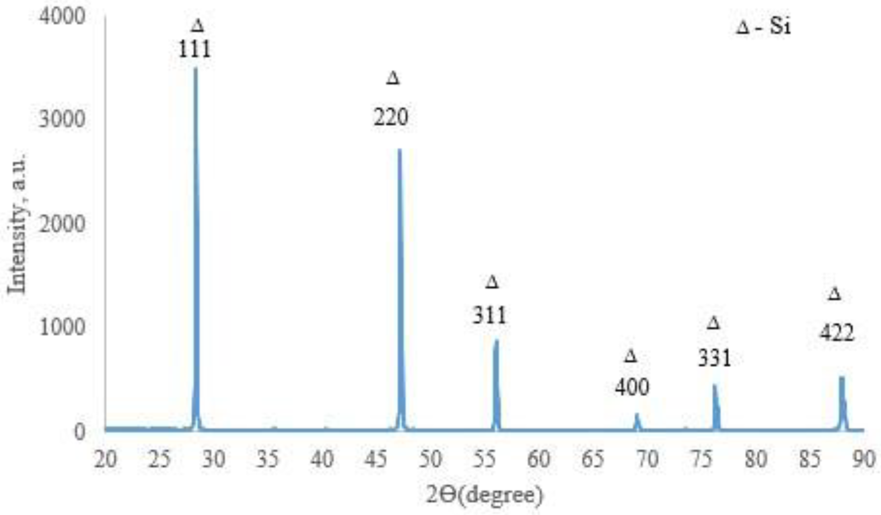
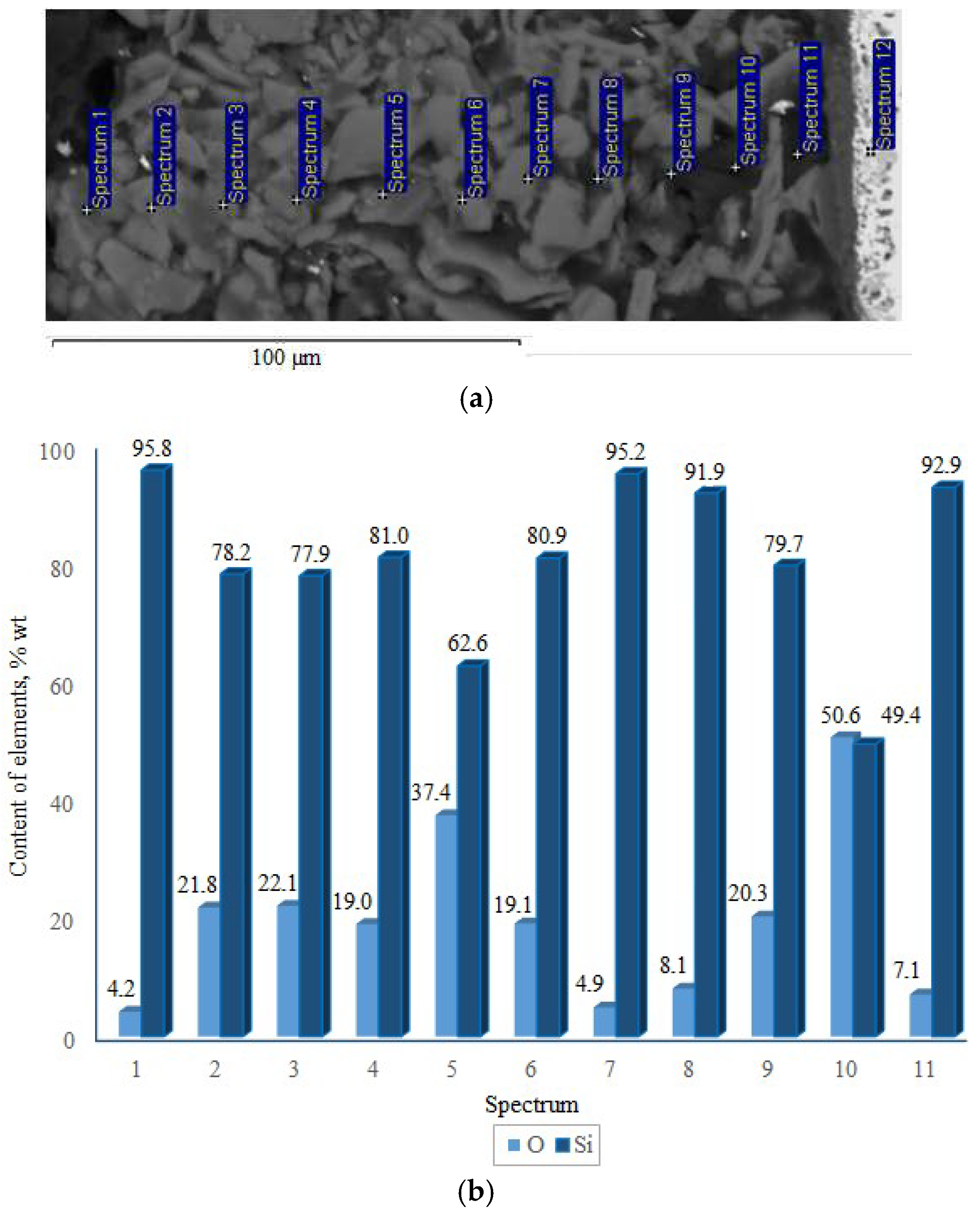
X-ray phase analysis revealed that the top coating layer corresponds to a crystalline silicon-based phase (a = 5.434 Å) (Figure 7). Boron was not detected in the top layer by XRD, likely due to its amorphous state or very low concentration. The weaker/smaller peaks observed in the range of 32–47° arise from diffraction by the inner layers of the coating, which are shielded by the upper polycrystalline silicon layer. SEM and EDX studies (Figure 8) showed that the coating consists of discrete particles of crystalline silicon and an amorphous SiO2-based phase. Dark, almost black inclusions were also observed within the coating, which may correspond to the amorphous boron phase introduced as a filler. However, this assumption cannot be technically confirmed at this stage.
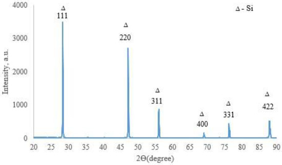
Figure 7.
X-ray diffractogram of the surface of TZM alloy after two-step treatment: complex saturation aluminium and silicon (aluminosiliconizing), and preceramic coating based on polyhydroxysilane modified with silicon and boron; CuKα radiation, wavelength—0.1541841 nm.
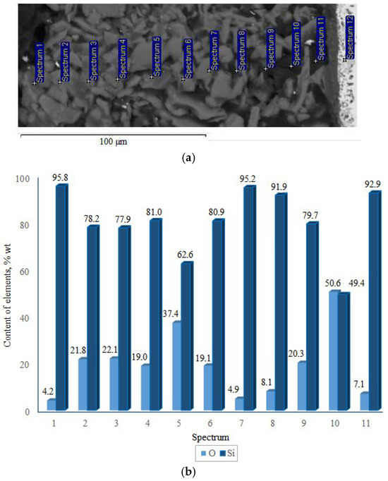
Figure 8.
Cross-section (a) and elemental distribution (b) of the TZM alloy coating after two-step treatment: complex saturation aluminium and silicon (aluminosiliconizing), and preceramic coating based on polyhydroxysilane modified with silicon and boron.
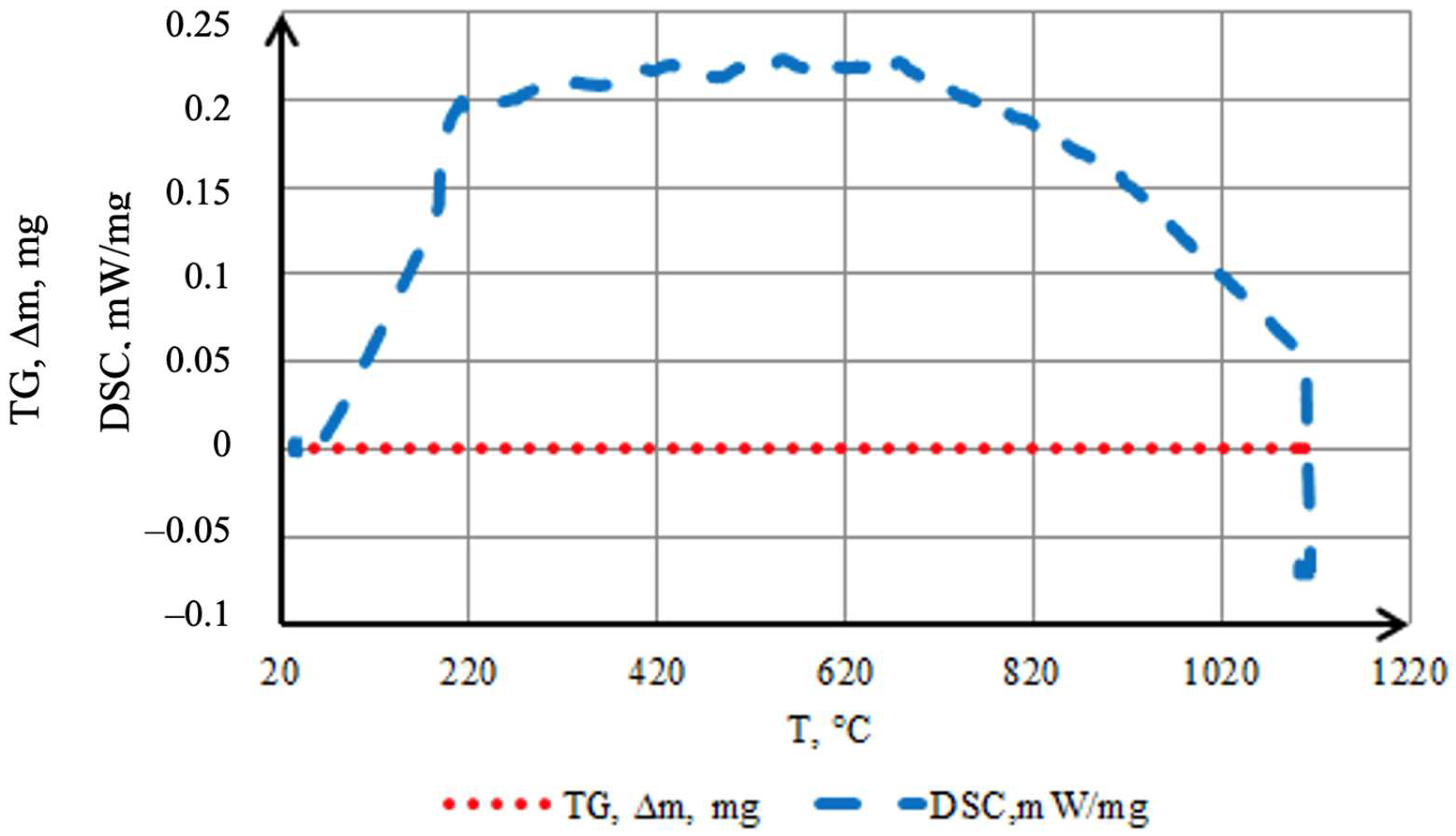
To evaluate the thermal stability of the coating in an inert atmosphere and to identify possible transformations accompanied by characteristic exothermic and endothermic reactions, TG–DSC analysis was performed (Figure 9). Samples with a mass of 0.3868 g (cylinders 1.5 mm in diameter and 3 mm in height) were used. Smaller samples could not be employed, as through-diffusion of the saturating elements may occur during the batch cementation process. The coating is uniform and fully covers the surface of the original sample. The results indicate a high stability of the formed layer in argon: the TG curve shows no mass change (∆m = 0) over the entire temperature range up to ~1100 °C, confirming its integrity and chemical inertness. An exothermic effect in the 50–200 °C range is attributed to the completion of structural transformations in the preceramic layer—cross-linking of Si–H groups in the polyhydrosilazane to form a Si–N–(O)–Si network, formation of an amorphous SiO2 phase, and partial oxidation of amorphous boron to B2O3. Processes related to the loss of residual moisture and the evaporation of polyhydrosilazane also occur within this temperature range [28,29]. Additionally, processes related to moisture evaporation or desorption may occur. The endothermic effect observed after the exothermic peak is associated with the removal of residual light fragments and the compaction of the amorphous borosilicate matrix. The process requires energy expenditure for the transition to a stable state.
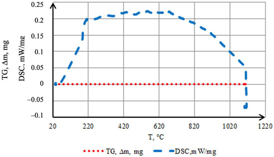
Figure 9.
Thermal behavior in argon of coatings obtained by two-step treatment: complex saturation with aluminium and silicon (aluminosiliconizing), and preceramic coating based on polyhydroxysilane modified with silicon and boron.
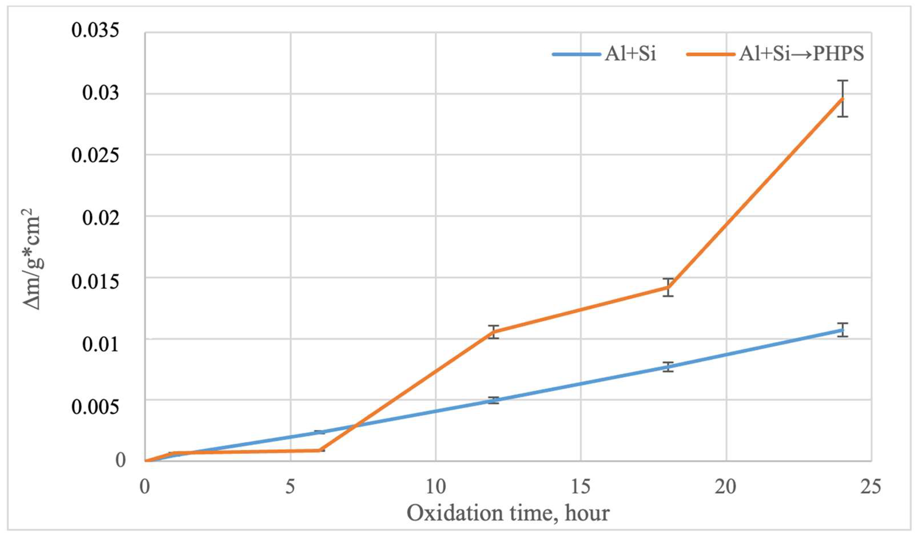
According to previously reported data [13], samples made from the TZM alloy undergo catastrophic corrosion under the given oxidation temperatures, completely evaporating after only 6 h of oxidation. This behavior is associated with the formation of the MoO3 phase, which sublimates at approximately 730 °C and can significantly evaporate [29,30,31]. The study of the oxidation kinetics of molybdenum with different types of coatings revealed a fundamental difference in their protective performance [32,33]. According to the data reported in [22], during the initial stage (up to 4 h of oxidation in air at 800 °C) for samples with PHPS/filler-based coatings, an increase in mass is observed, which is associated with the formation of a glassy SiO2 or SiO2–B2O3 layer on the sample surface. Subsequent changes in mass as a function of time are negligible, indicating surface passivation by the protective film. Figure 10 shows the mass change in the samples during cyclic oxidation at 800 °C on air, a temperature critical for the TZM molybdenum alloy [13].
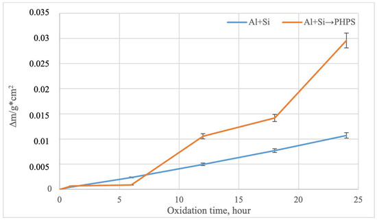
Figure 10.
Oxidation kinetics of the TZM alloy with different coatings (800 °C, 24 h).
For the samples with coatings obtained by complex aluminosiliconizing, a moderate, nearly linear increase in mass is observed, which is due to the formation of a stable Al2O3–SiO2 oxide layer that effectively limits oxygen diffusion to the substrate. Samples with coatings obtained via two-step treatment exhibit a more pronounced mass gain, especially in the later stage of the test (after 18 h). This indicates the active formation of additional layers based on SiO2 and B2O3. B2O3 can evaporate at high temperatures; however, its interaction with SiO2 leads to the formation of borosilicate glass, which effectively reduces its vapor pressure and limits evaporation. B2O3 can evaporate at high temperatures. However, its interaction with SiO2 leads to the formation of borosilicate glass, which effectively reduces its partial pressure and limits evaporation. The absence of mass loss in both cases confirms the integrity of the coatings throughout the oxidation cycle. In the presence of defects in the protective layer, molybdenum would oxidize to volatile MoO3, resulting in mass loss due to evaporation [13].
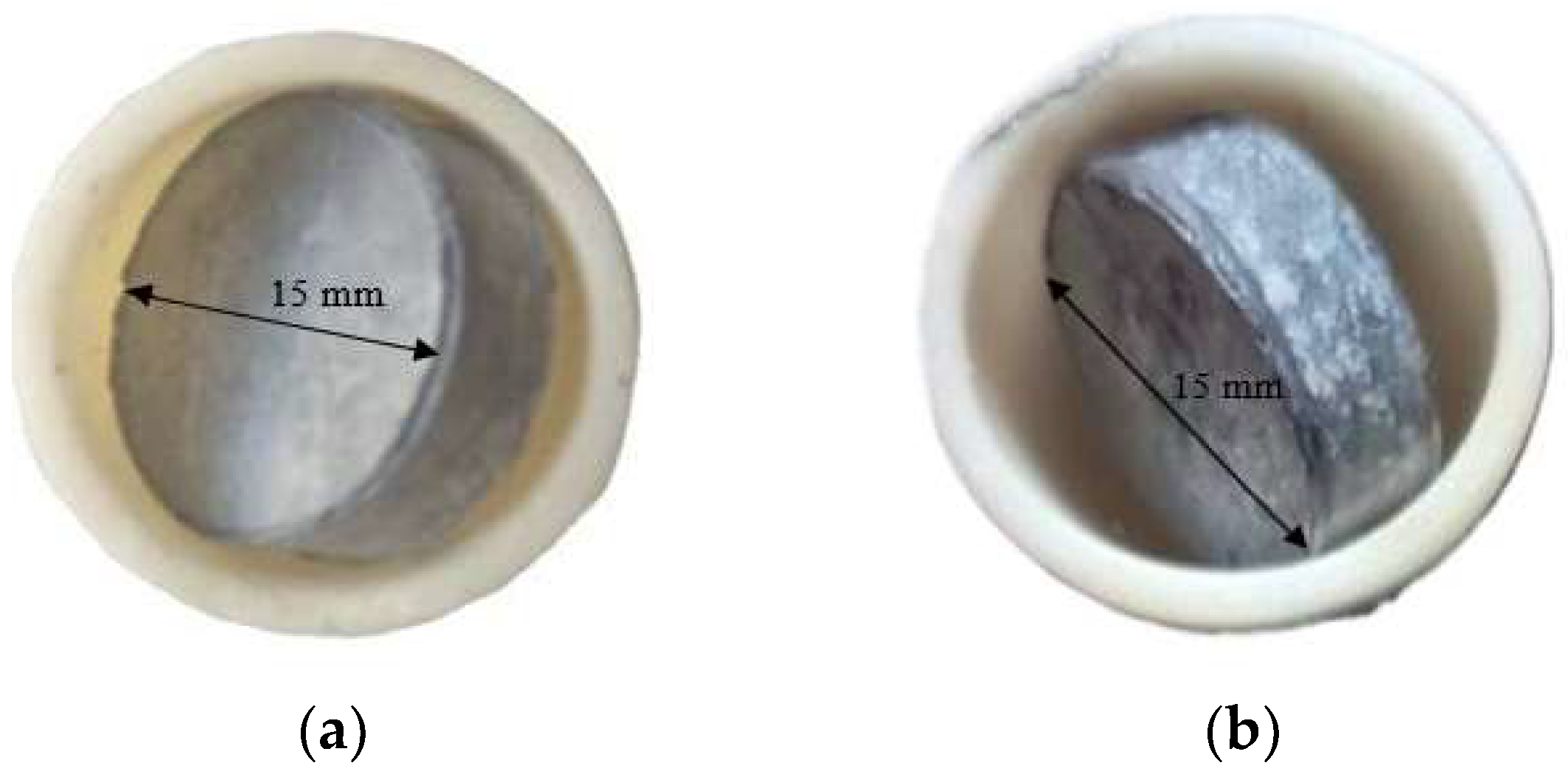
After 24 h of high-temperature oxidation, the surfaces of the samples exhibited significant visual changes. For both types of coatings, a color change is observed, indicating the formation of oxide phases. In the case of the coating obtained by aluminosiliconizing, the gray color turns light gray, which may be associated with the formation of Al2O3-enriched oxides (Figure 11a).
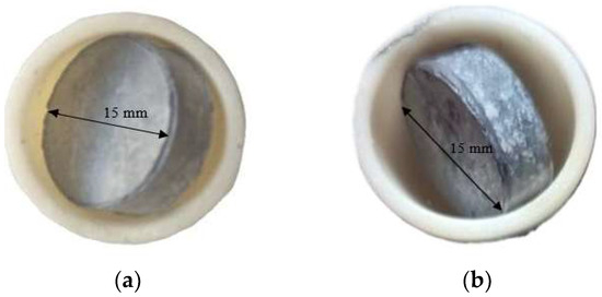
Figure 11.
Appearance of TZM molybdenum alloy subjected to aluminosiliconization (a) and to two-step treatment (aluminosiliconizing, and preceramic coating based on polyhydroxysilane modified with silicon and boron) (b) after oxidation at 800 °C for 24 h.
For coatings obtained through the two-step treatment, the initially dark gray coating with a slight brownish tint, characteristic of the as-prepared state (Figure 1b), changes to light gray with distinct white inclusions (Figure 11b).
The color change is attributed to the formation of a protective oxide layer, which likely consists predominantly of silicon dioxide (SiO2) and boron oxide (B2O3). These compounds are known for their high chemical stability, low volatility, and ability to form continuous amorphous (glassy) films that prevent from further oxidation of the metallic substrate [27,28,34].
SiO2 typically forms a dense, glass-like structure with low oxygen permeability, providing a barrier against further oxidation [31,35]. B2O3, in turn, can lower the surface binding temperature by forming low-melting eutectics that promote self-healing of microdefects in the oxide layer. Additionally, oxidation in air may lead to the formation of an amorphous, multicomponent oxide phase, which optically manifests as surface lightening due to increased light scattering [31,35].
Macro-analysis shows that the surface retains its integrity, with no signs of cracking or delamination, indicating the mechanical compatibility of the oxide layer with the metallic substrate and its effectiveness as a diffusion barrier.
Thus, both coatings effectively protect molybdenum from oxidation. The coating obtained via the two-step treatment demonstrates an additional ability to form a thicker protective layer and maintain integrity during high-temperature oxidation.
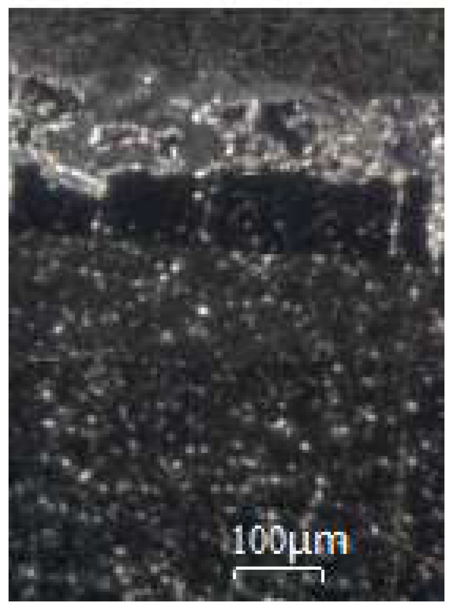
Microstructural analysis (Figure 12) revealed that a light-colored layer with a thickness of 120–130 μm was formed on the outer surface of the coating (two-step treatment and oxidation at 800 °C for 24 h).
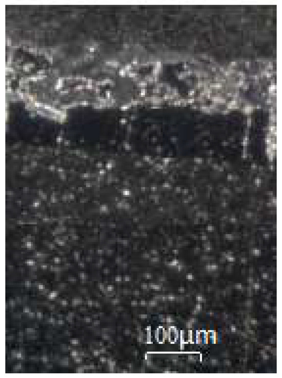
Figure 12.
Microstructure of the coating of TZM molybdenum alloy (aluminosiliconizing, and preceramic coating based on polyhydroxysilane modified with silicon and boron) after oxidation at 800 °C for 24 h.
This layer is the product of PHPS filled with boron and silicon, after polymer-to-ceramic transformation under the chosen oxidation conditions. The layer exhibits a clear boundary with the underlying dark layer applied by the batch cementation method and is characterized by the high density typical of glassy and ceramic materials. However, morphological features indicate that the formation of a fully homogeneous glassy structure is not yet complete due to the relatively short holding time. Nevertheless, even at this stage, the outer layer effectively isolates and fills the pores and cracks in the inner layer.
4. Conclusions
- The coating formed by pack cementation via complex aluminosiliconizing of the TZM alloy produces a uniform, multilayer diffusion layer (20–30 µm) with zones enriched in intermetallic phases (Al63Mo37, MoAl3), nitrides (Mo2N, AlN, Si3N4), and oxides (Al2O3), as well as a solid solution of α-Mo(Al,Si).
- The two-step technology, which involves applying a preceramic layer based on polysilazane filled with silicon and boron, ensures the formation of a transitional oxide layer ((Al,Si)2O3) 5–7 µm thick and an outer layer (130–160 µm) composed of crystalline Si, amorphous SiO2, and likely amorphous boron. This structure densifies the surface and seals defects in the cementation coating.
- TG–DSC analysis indicates the high thermal stability of the coating up to 1200 °C in an argon atmosphere. The absence of mass loss and the presence of characteristic exo-/endothermic effects confirm the completion of crosslinking of the preceramic polymer and stabilization of the corresponding ceramic phase.
- Oxidation resistance tests at 800 °C showed the effectiveness of both coating types. The combined coating forms additional oxide barriers (SiO2, B2O3) that preserve mass and layer integrity, preventing the formation of molybdenum oxides.
Thus, the application of a combination of aluminosiliconizing and preceramic polysilazane-based coating modified with silicon and boron enables the formation of a multilayer barrier coating with high thermal and oxidation resistance.
Author Contributions
Conceptualization, M.S., M.K. (Manja Krüger) and T.L.; methodology, T.L. and M.S.; software, N.K. and V.T.; validation, M.K. (Myroslav Karpets), G.H. and N.K.; formal analysis, G.H., Y.S. and V.T.; investigation, T.L., M.S., M.K. (Myroslav Karpets) and N.K.; resources, M.K. (Myroslav Karpets), G.H. and Y.S.; data curation, M.K. (Myroslav Karpets) and G.H.; writing—original draft preparation, T.L. and N.K.; writing—review and editing, N.K. and V.T.; visualization, M.K. (Myroslav Karpets), V.T. and G.H.; supervision, M.S., M.K. (Manja Krüger) and T.L.; project administration, M.S. and M.K. (Manja Krüger). All authors have read and agreed to the published version of the manuscript.
Funding
This research was funded by German Research Foundation (DFG), Grant ID 550760674.
Data Availability Statement
The original contributions presented in the study are included in the article, further inquiries can be directed to the corresponding author.
Conflicts of Interest
The authors declare no conflict of interest.
References
- Perepezko, J.H.; Sakidja, R. Oxidation-resistant coatings for ultra-high-temperature refractory Mo-based alloys. JOM 2010, 62, 13–19. [Google Scholar] [CrossRef]
- Beck, K.; Ulrich, A.S.; Czerny, A.; White, E.; Heilmaier, M.; Galetz, M. Aluminide diffusion coatings for improving the pesting behavior of refractory metals. Surf. Coat. Technol. 2023, 476, 130205. [Google Scholar] [CrossRef]
- Fu, T.; Shen, F.; Zhang, Y.; Yu, L.; Cui, K.; Wang, J.; Zhang, X. Oxidation Protection of High-Temperature Coatings on the Surface of Mo-Based Alloys—A Review. Coatings 2022, 12, 141. [Google Scholar] [CrossRef]
- Fu, T.; Cui, K.; Zhang, Y.; Wang, J.; Zhang, X.; Shen, F.; Yu, L.; Mao, H. Microstructure and Oxidation Behavior of Anti-Oxidation Coatings on Mo-Based Alloys through HAPC Process: A Review. Coatings 2021, 11, 883. [Google Scholar] [CrossRef]
- Park, J.S.; Kim, J.; Kim, H.; Yi, S.; Perepezko, J.H. Oxidation resistance coatings of Mo–Si–B alloys via a pack cementation process. Met. Mater. Int. 2008, 14, 1–7. [Google Scholar] [CrossRef]
- Choi, K.; Yang, W.; Baik, K.; Kim, Y.; Lee, S.; Lee, S.; Park, J.S. Growth kinetics and isothermal oxidation behavior of a Si pack cementation-coated Mo–Si–B alloy. Appl. Surf. Sci. 2019, 489, 111–118. [Google Scholar] [CrossRef]
- Lange, A.; Heilmaier, M.; Sossmann, T.; Perepezko, J.H. Oxidation behavior of pack-cemented Si–B oxidation protection coatings for Mo–Si–B alloys at 1300 °C. Surf. Coat. Technol. 2015, 266, 10–15. [Google Scholar] [CrossRef]
- Lu-Steffes, O.; Sakidja, R.; Bero, J.; Perepezko, J.H. Multicomponent coating for enhanced oxidation resistance of tungsten. Surf. Coat. Technol. 2012, 207, 614–619. [Google Scholar] [CrossRef]
- Perepezko, J.H. Environmental resistant coatings for high temperature Mo and Nb silicide alloys. MRS Adv. 2017, 2, 1323–1334. [Google Scholar] [CrossRef]
- Efremenko, B.V.; Shimizu, K.; Espallargas, N.; Efremenko, V.G.; Kusumoto, K.; Chabak Yu, G.; Belik, A.G.; Chigarev, V.V.; Zurnadzhy, V.I. High-temperature solid particle erosion of Cr–Ni–Fe–C arc cladded coatings. Wear 2020, 460–461, 203439. [Google Scholar] [CrossRef]
- Sakidja, R.; Park, J.S.; Hamann, J.; Perepezko, J.H. Synthesis of oxidation resistant silicide coatings on Mo–Si–B alloys. Scr. Mater. 2005, 53, 1283–1288. [Google Scholar] [CrossRef]
- Loskutova, T.; Scheffler, M.; Ivanov, V.; Pohrebova, I.; Kononenko, Y.; Bobina, M.; Kharchenko, N.; Bartoszuk, M.; Pavlenko, I. Physicochemical Conditions of Boron–Siliconizing of Molybdenum-Based Alloys in Chlorine and Fluorine Medium. Metals 2024, 14, 302. [Google Scholar] [CrossRef]
- Loskutova, T.; Scheffler, M.; Ivanov, V.; Krueger, M.; Kharchenko, N.; Taran, V.; Hatala, M.; Karpets, M.; Stelmakh, Y.; Hasemann, G. Influence of diffusion siliconizing and boron–siliconizing in chlorine-containing environments on the structure, composition, and protective properties of TZM molybdenum alloy. Appl. Surf. Sci. Adv. 2025, 27, 100769. [Google Scholar] [CrossRef]
- Perepezko, J.H. High temperature environmental resistant Mo-Si-B based coatings. Int. J. Refract. Met. Hard Mater. 2017, 71, 99–107. [Google Scholar] [CrossRef]
- Anton, R.; Hüning, S.; Laska, N.; Weber, M.; Schellert, S.; Gorr, B.; Christ, H.-J.; Schulz, U. Graded PVD Mo-Si interlayer between Si coating and Mo-Si-B alloys: Investigation of oxidation behaviour. Corros. Sci. 2021, 192, 109843. [Google Scholar] [CrossRef]
- Kochmańska, A.E.; Jarlaczyńska, A.; Baranowska, J. Formation of Silicide and Silicide-Aluminide Coatings on Molybdenum Alloy during Slurry Cementation Process: Influence of Slurry Volume. Materials 2021, 14, 6940. [Google Scholar] [CrossRef]
- Perepezko, J.H.; Rioult, F.; Sakidja, R. Oxidation performance of high temperature Mo-Si-B alloys and coatings. Mater. Sci. Forum 2008, 595–598, 1065–1074. [Google Scholar] [CrossRef]
- Görke, O.; Feike, E.; Heine, T.; Trampert, A.; Schubert, H. Ceramic coatings processed by spraying of siloxane precursors. J. Eur. Ceram. Soc. 2004, 24, 2141–2147. [Google Scholar] [CrossRef]
- Günthner, M.; Wang, K.; Bordia, R.K.; Motz, G. Conversion Behaviour Resulting Mechanical Properties of Polysilazane-Based Coatings. J. Eur. Ceram. Soc. 2012, 32, 1883–1892. [Google Scholar] [CrossRef]
- Gatzen, C.; Smokovych, I.; Scheffler, M.; Krüger, M. Oxidation-resistant environmental barrier coatings for Mo-based alloys. Adv. Eng. Mater. 2020, 22, 2001016. [Google Scholar] [CrossRef]
- Günthner, M.; Schütz, A.; Glatzel, U.; Wang, K.; Bordia, R.K.; Greißl, O.; Krenkel, W.; Motz, G. High performance environmental barrier coatings, Part I: Passive filler loaded SiCN system for steel. J. Eur. Ceram. Soc. 2011, 31, 3003–3010. [Google Scholar] [CrossRef]
- Smokovych, I.; Gatzen, C.; Krüger, M.; Schwidder, M.; Scheffler, M. Polymer Derived Ceramics from Si, B, SiB6, and Mo5SiB2 Filler-Loaded Perhydropolysilazane Precursors as Protective and Functional Coatings for Refractory Metal Alloys. Materials 2020, 13, 4878. [Google Scholar] [CrossRef] [PubMed] [PubMed Central]
- Chakraborty, S.P.; Banerjee, S.; Singh, K.; Sharma, I.G.; Grover, A.K.; Suri, A.K. Studies on the development of protective coating on TZM alloy and its subsequent characterization. J. Mater. Process. Technol. 2008, 207, 240–247. [Google Scholar] [CrossRef]
- Shevko, V.M.; Badirova, N.B. Thermodynamic Modeling of ZnO Chlorination by Chlorohydrocarbons by Using B«AstraB» Software. Eurasian Chem. Technol. J. 2010, 12, 165–170. [Google Scholar] [CrossRef]
- Okamoto, H. Desk Handbook: Phase Diagrams for Binary Alloys, 2nd ed.; ASM International: Materials Park, OH, USA, 2010. [Google Scholar]
- Hu, Q.; Xue, Z.; Song, S.; Cromarty, R.; Chen, Y. Utilization of Silicon Dust to Prepare Si3N4 Used for Steelmaking Additives: Thermodynamic and Kinetics. Processes 2024, 12, 301. [Google Scholar] [CrossRef]
- Smokovych, I.; Bolbut, V.; Krüger, M.; Scheffler, M. Tailored oxidation barrier coatings for Mo-Hf-B and Mo-Zr-B alloys. Materials 2019, 12, 2215. [Google Scholar] [CrossRef]
- Zhao, X.; He, X.; Zhang, S.; Wang, L.; Li, M.; Li, Y. Investigations on B-doped SiO2 thermal protective coatings by hybrid sol–gel method. Thin Solid Film. 2011, 519, 4849–4854. [Google Scholar] [CrossRef]
- Parthasarathy, T.; Mendiratta, M.; Dimiduk, D. Oxidation mechanisms in Mo-reinforced Mo5SiB2(T2)–Mo3Si alloys. Acta Mater. 2002, 50, 1857–1868. [Google Scholar] [CrossRef]
- Knapp, S.; Eisenreich, N.; Kuchenreuther-Hummel, V.; Kelzenberg, S.; Koleczko, A.; Schuppler, H. Thermogravimetric analysis of molybdenum oxide (MoO3) decomposition. In Proceedings of the 47th International Annual Conference of ICT, Karlsruhe, Germany, 28 June–1 July 2016; Volume 113. No. 1. Available online: https://publica-rest.fraunhofer.de/server/api/core/bitstreams/84e53a3b-5e1f-47b2-b476-346c00bebdd2/content (accessed on 29 September 2025).
- Samsonov, G.V. (Ed.) The Oxide Handbook; Springer: Boston, MA, USA, 1973. [Google Scholar] [CrossRef]
- Majumdar, S.; Sharma, I.G.; Raveendra, S.; Samajdar, I.; Bhargava, P. In situ chemical vapour co-deposition of Al and Si to form diffusion coatings on TZM. Mater. Sci. Eng. A 2008, 492, 211–217. [Google Scholar] [CrossRef]
- Wang, Y.; Wang, D.; Yan, J.; Sun, A. Preparation and characterization of molybdenum disilicide coating on molybdenum substrate by air plasma spraying. Appl. Surf. Sci. 2013, 284, 881–888. [Google Scholar] [CrossRef]
- Sun, G.D.; Li, H.J.; Fu, Q.G.; Zhang, Q. Effect of B2O3/SiO2 mass ratio on oxidation resistant property of phosphate coating for C/C composites. Mater. Res. Innov. 2014, 18 (Suppl. S4), S4-715–S4-718. [Google Scholar] [CrossRef]
- Liang, J.; Zhang, M.; Peng, Y.; Wang, J. Advances in Understanding the Evolution Mechanism of Micropore Defects in Metal Materials under External Loads. Metals 2024, 14, 522. [Google Scholar] [CrossRef]
Disclaimer/Publisher’s Note: The statements, opinions and data contained in all publications are solely those of the individual author(s) and contributor(s) and not of MDPI and/or the editor(s). MDPI and/or the editor(s) disclaim responsibility for any injury to people or property resulting from any ideas, methods, instructions or products referred to in the content. |
© 2025 by the authors. Licensee MDPI, Basel, Switzerland. This article is an open access article distributed under the terms and conditions of the Creative Commons Attribution (CC BY) license (https://creativecommons.org/licenses/by/4.0/).

