Article

Microstructure and Mechanical Behavior of Magnetron Co-Sputtering MoTaN Coatings

Department of Materials Science and Engineering, National United University, Miaoli 360302, Taiwan
*
Author to whom correspondence should be addressed.
Coatings 2025, 15(1), 80; https://doi.org/10.3390/coatings15010080
Submission received: 22 September 2024 / Revised: 6 November 2024 / Accepted: 12 November 2024 / Published: 13 January 2025
(This article belongs to the Special Issue Sputtering Deposition for Advanced Materials and Interfaces)

Abstract

:
In recent years, there have been important developments in the refractory metal nitride coatings used for versatile applications, such as MoN, TaN, NbN, etc. Engineered approaches, including the deposition method, microstructure control, structural design, and the addition of functional elements, are put into practice for the promotion of coating characteristics. This study focuses on the microstructure and mechanical properties of ternary molybdenum tantalum nitride, MoTaN, coatings. MoTaN was deposited using a reactive radio frequency (r.f.) magnetron co-sputtering system with Mo/Ta target input power modulation control. The effects of composition and microstructure variations on its mechanical properties, including its hardness, elastic modulus, and wear behavior, were investigated. In general, the MoTaN coatings exhibited a columnar polycrystalline microstructure with MoN(111), Mo2N(111), Mo2N(200), TaN(200), and TaN(220) phases and orientations based on X-ray diffraction analysis. The addition of Ta triggered the transition of the primary orientation of Mo2N(111) into Mo2N(200). Transmission electron microscopy was utilized to analyze the transformation of the multiphase structure and changes in the grain size in terms of the Ta addition. According to nanoindentation and wear resistance analyses, superior hardness, elastic modulus, H/E, H3/E2, and wear-resistance values were identified for the MoTaN coatings with 6.8 to 10.4 at.% Ta, and a maximum hardness of 18.0 GPa was found for the MoTaN coating deposited at an input power of Mo/Ta = 150/100 W/W. An optimized hardness of 18.0 GPa and an elastic modulus of 220.7 GPa were obtained. The adjustment of the input power during deposition played a critical role in determining the overall performance of the MoTaN co-sputtering coatings. The MoTaN coating with optimized mechanical properties is attributed to its multiphase microstructure and fine columnar grain size of less than 30 nm.

1. Introduction

In order to improve the mechanical properties of tool or component parts, such as ball bearings, drilling bits, and cutting tools, protective coatings have been developed over decades in the surface engineering industry. In particular, transition metal nitride, TMN, coatings, which have excellent mechanical properties, such as high hardness, outstanding wear resistance, and chemical stability, attract tremendous attention among the hard surface coatings [1,2,3]. In recent years, binary transition metal nitride coatings, including TiN [4], MoN [5], NbN [6], WN [7], ZrN [8], and TaN [9], have been intensively studied and manipulated to achieve superior mechanical performance. To further enhance their mechanical performance, the addition of a second element to form a ternary transition metal nitride system has been put into practice. The elements of choice include non-metals, like Si [10], B [11], and C [12], and metals, like Ag [13], V [14], and Cu [15]. Compared with binary nitride films, the development of ternary nitrides is less extensive due to complexities in their microstructure and process control. Nevertheless, recent studies have shown encouraging results in the development of TMN films. The MoN coating has the advantages of a low friction coefficient, self-lubrication, and outstanding chemical stability [16,17,18]. The formation of a MoO3 phase was demonstrated to be beneficial for the reduction of friction force and promotion of anti-wear performance. On the other hand, TaN coatings have been recognized for their wear resistance, high hardness, and chemical and thermal stability [9,19]. The face-centered cubic, fcc, structure of TaN(111) and TaN(200) has been investigated in Bernoulli’s and Zaman’s works. The demonstration that the hardness of TaN(200) is superior to that of TaN(111) [9] implies that a crystal orientation is essential to the mechanical strength of TMN layers. To further improve TMN film characteristics, additional functional elements and sophisticated control of the fabrication process and coating microstructure are put into practice. In ternary transition metal nitride coatings, complex microstructures, solid solutions, and grain refinement are manipulated to enhance the mechanical properties of tools. For example, Li and coworkers [20] demonstrated the enhanced mechanical characteristics of ternary refractory metal nitride of sub-stoichiometric B1 Ta-Mo-Nx films. In Qiu’s research [21], for instance, the grain size of TiN coatings was found to decrease with the addition of silicon. In Wang’s investigation [22], the peak shift toward lower angles in CrAlN thin films was attributed to the solid solution effect, and excellent mechanical properties are expected. The combination of MoN and TaN, or adding Ta into MoN, to form a MoTaN coating could be one attempt to create a new protective coating system. In summary, ternary transition metal nitrides formed with a combination of MoN and TaN under process control and microstructure evolution could garner significant interest and have research potential.
This work aims to understand the relationships among the manufacture, microstructure, and mechanical behavior of reactive radio frequency (r.f.) magnetron co-sputtering MoTaN coatings. The coatings’ composition and microstructure are evaluated and discussed in terms of the input power modulation of Mo/Ta. The mechanical properties of the MoTaN films, including their hardness, elastic modulus, and wear behavior, as a function of their composition and microstructure are investigated and analyzed. The strengthening mechanism of the MoTaN coatings is discussed.

2. Experimental Procedure

MoTaN thin films were deposited on silicon wafers and AISI 420 stainless steel substrates (Summit-Tech, Hsinchu, Taiwan) through a reactive r.f. magnetron co-sputtering system with dual sputtering sources. Both substrates were polished and ultrasonically cleaned with acetone, alcohol, and deionized water to create a proper surface condition for deposition. The Mo and Ta metallic target substrates, both with a purity of 99.995% and dimensions of 25.4 and 6 mm in radius and thickness, respectively, were then installed in the above-mentioned vacuum coating apparatus. An evacuation process was then conducted, reducing the background pressure to 6 × 10⁻⁶ Torr. A MoTa alloy interlayer was deposited onto the substrates under an input power of 100 W for each target, with a 20 s.c.c.m. Ar gas inlet, followed by the inlet of a Ar and N2 gas mixture of 12 and 8 s.c.c.m., respectively, to a working pressure of 5 × 10⁻² Torr. The substrates were heated to and kept at 350 °C during the film deposition. The working plasma was ignited and manipulated under a fixed input power at 150 W on the Mo target, and the tuning power on the Ta target ranged from 0 to 150 W. Details of the input power modulation and the resulting composition, elemental ratios, and deposition rate are summarized in Table 1. The deposition of the MoN layer, i.e., the Mo/Ta input power modulation of 150/0 W/W, was also conducted with reference to Liao’s work [23]. The total thickness of each MoTaN coating was controlled to approximately 1 μm, with a pure MoTa metallic intermediate layer thickness of around 100 nm.
The microstructure and mechanical characteristics of the co-sputtering MoTaN coatings were analyzed and discussed. The chemical composition of the layers was inspected by field emission electron probe microanalysis (FE-EPMA, JXA-8500F, JEOL, Tokyo, Japan). Phase identification of the films was carried out through the X-ray diffraction technique (XRD, Ultima IV, Rigaku, Tokyo, Japan) using a conventional theta-2 theta scan with Cu Kα as the incident source. The high-resolution transmission electron microscope (HR-TEM, JEM-2100, JEOL, Tokyo, Japan) with selected area electron diffraction, SAED, and dark-field image analysis were utilized to determine the detailed microstructure and phase of the MoTaN coatings. The hardness and reduced Young’s modulus of the MoTaN samples were measured by nanoindentation (TriboIndenter, TI 900, Hysitron, Minneapolis, MN, USA). The depth was set to approximately 100 nm with a 5 s dwelling time for reliable indentation and quality data. At least 5 indents were made and statistically summarized for one hardness value of a specimen. The H/E and H3/E2 indices were calculated accordingly. A wear test was conducted with a linear back-and-forth pin-on-substrate wear tester (abrasion-resistance tester, A20-339, Jiinnliang, Taipei, Taiwan) against a counterpart of an Al2O3 ball with a diameter of 5 mm under a fixed normal load of 3.2 N and a total sliding length of 50 m. The worn surface was investigated by optical microscopy (OM, VHX-6000, KEYENCE, Taipei, Taiwan).

3. Results and Discussion

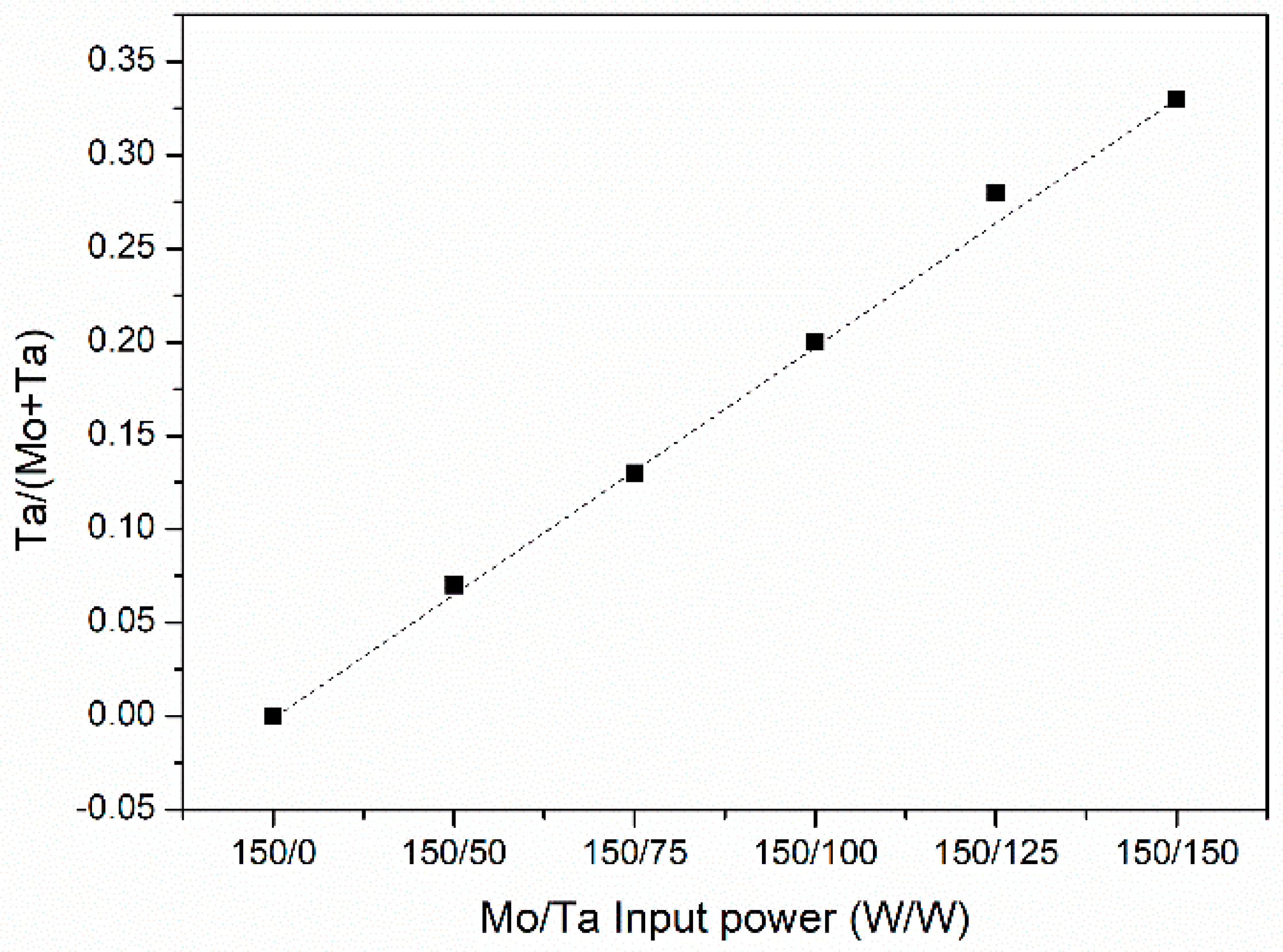
3.1. Fabrication and Composition Analysis

Table 1 shows the designed input power modulation from Mo/Ta = 150/0 to 150/150 W/W and the resultant composition, elemental ratio, and deposition rates of the MoTaN coatings designated from A to F. Sample A refers to MoN, and samples B to F represent various MoTaN films. As the input power on the Ta target increased from 50 to 150 W, the Mo contents decreased from 46.4 to 34.5 at.%, while the Ta contents rose from 3.7 to 16.8 at.%. It should be noted that under the input power of 150 W for both targets, i.e., sample F, the composition of Mo was higher than that of Ta [24,25]. In [24], regardless of the incident ion energies, the sputtering yield of Mo was higher than that of Ta, and thus, Mo-dominated nitride films were evident. The incorporation of Ta in a monotonic increase with respect to the Ta input power was revealed, as plotted in Figure 1. The dependence of the elemental atomic percentage as a function of input power modulation was calculated and is presented. The decrease in the Mo and the increase in the Ta in the MoTaN coatings show similar correlations of approximately 3.0 and 3.3, respectively. Consequently, the N was constant in all coatings. In Figure 2, the dependence of the input power on the Ta ratio, i.e., the Ta/(Mo + Ta), in the nitride films is illustrated. A linear proportion of the Ta/(Mo + Ta) ratio versus the Mo/Ta power modulation again was demonstrated, showing a well-controlled co-sputtering process for MoTaN deposits. It was observed that the N contents were kept at approximately 50 at.% for the MoTaN films, as listed in Table 1. The ratio of (Mo + Ta)/N was stable at around unity regardless of the Mo/Ta input power modulation, implying steady nitride formation and stable stoichiometry during the reactive co-sputtering process. Due to the rising Ta flux in the plasma as the Ta input power increased, the deposition rate of the MoTaN films rose accordingly from 5.4 to 6.7 nm/min.

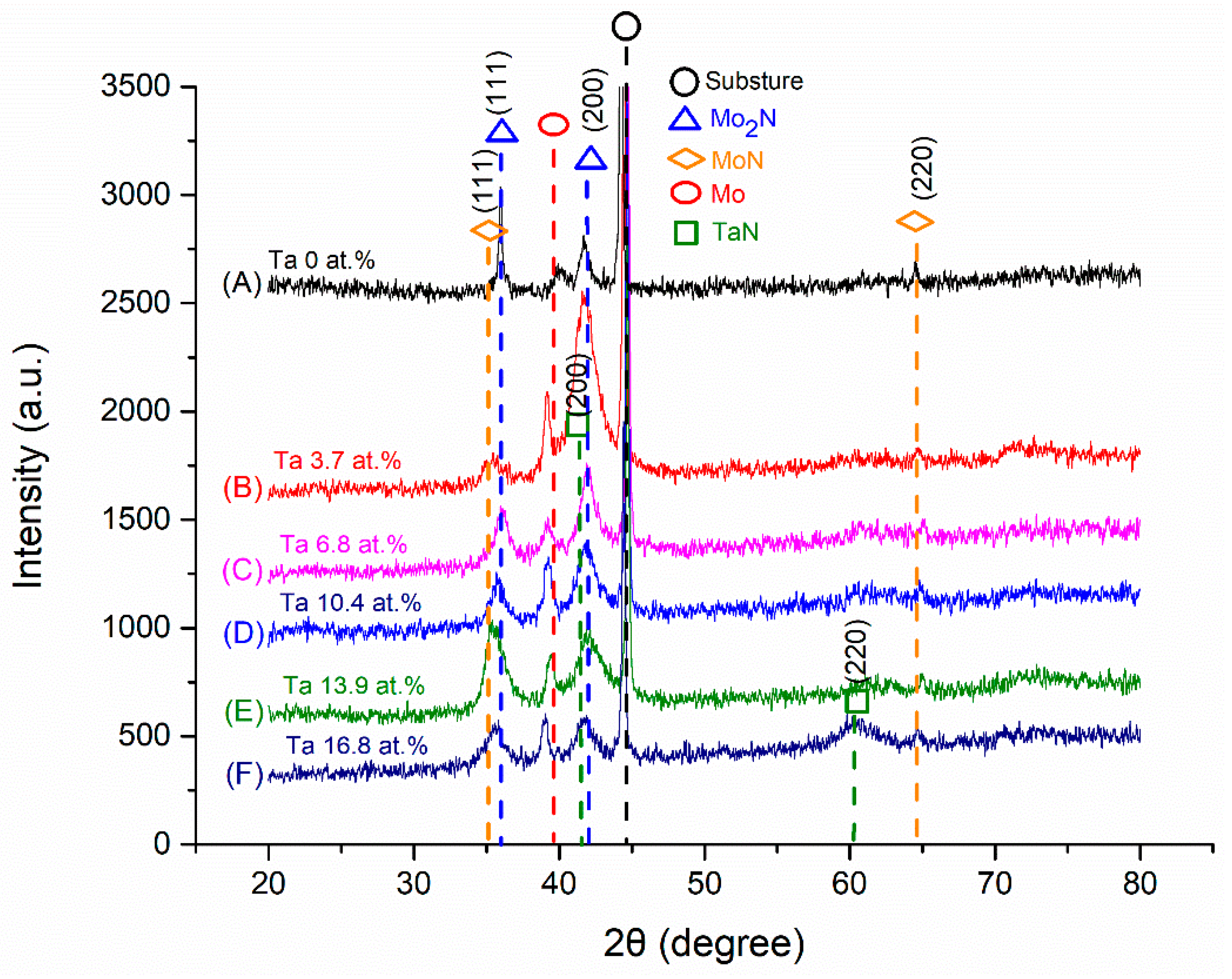
3.2. Phase Identification Through X-Ray Diffraction

Figure 3 presents the X-ray diffraction patterns of the MoN and MoTaN films. The diffraction peak of Mo(110), which reflects the MoTa interlayer, is shown for all samples. The MoN, i.e., sample A, exhibited peaks corresponding to MoN(111), MoN(220), Mo2N(111), and Mo2N(200). The MoTaN layers, samples B to F, on the other hand, exhibited not only Mo-N related phases (MoN(111), MoN(220), Mo2N(111), and Mo2N(200)) but also TaN phase with (200) and (220) orientations. For samples A and B, which possessed a very low Ta content of 3.7 at.%, a polycrystalline microstructure of multiple Mo-N phases was displayed, including MoN(111), MoN(220), Mo2N(111), and Mo2N(200). In the literature, the peaks of Mo2N(111), Mo2N(200), and MoN(111) were confirmed in the range of 35–45° [1,5] for r.f.-fabricated Mo-N films, while the peaks of TaN(100) and TaN(200) were also demonstrated around 35–42° for TaN films deposited by the r.f. reactive sputtering method [9,19]. However, in the present case, there was no TaN phase or facet found in sample B. Yet, with a small amount of tantalum, the main phase and facet of sample B transformed from Mo2N(111) to Mo2N(200), as judged by these diffraction peaks. Such a phenomenon could be referred to as a solid solution of Ta in the Mo-N phases. Simultaneously, the addition of Ta inhibited Mo2N(111) crystals, promoting the growth of Mo2N(200). For sample B, the main peak was Mo2N(200) and its intensity decreased with the addition of Ta.
When the input power of Ta was further increased to 75–100 W for samples C and D, the small yet distinguishable TaN(220) peak started to appear at approximately 60°. Meanwhile, the peak intensity of Mo2N(200) at 41° decreased, as shown in Figure 3. Samples C and D represent a transition region from a major Mo2N(200) peak to the formation of TaN. The broadened peak with decreased intensity in the range of 40–42° could be attributed to both Mo2N(200) and TaN(200). The small peak of TaN(220) at 60° for samples C to F provides evidence of the co-existence of Mo2N and TaN phases. It can be argued that there is competitive growth between Mo2N(200) and TaN(200), since the diffraction peak’s full width at half maximum (FWH), at 40–42° of samples C and D, was wider than that of sample B. For samples E and F, with 125 and 150 W of input power on the Ta target, respectively, the major peaks at 41° correspond to Mo2N(200) and TaN(200). For sample F, all of the peaks were further broadened with reduced intensities owing to the multiphase nature of the coating. For samples B to F, the addition of Ta caused the widening of the full width at half maximum of Mo2N(200), implying a decreased crystal size of Mo2N(200) and competitive growth of the TaN phase. In the present study, the TaN phase was discovered as the input power of Ta was raised to 75 W and higher. A multiphase microstructure of the MoTaN coatings was demonstrated. Detailed microstructure observation was carried out through transmission electron microscopy.

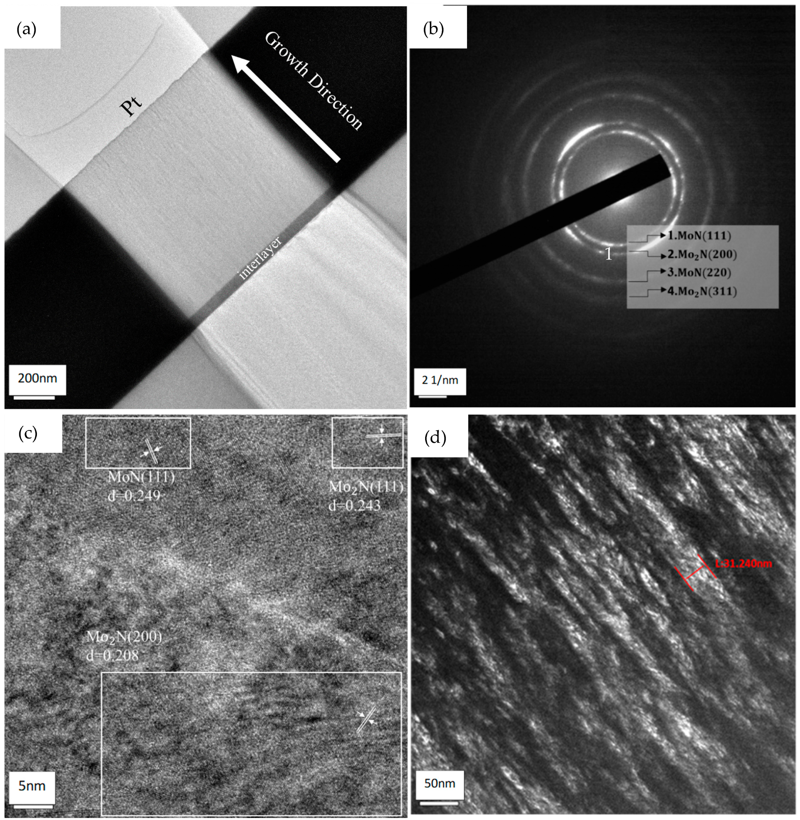
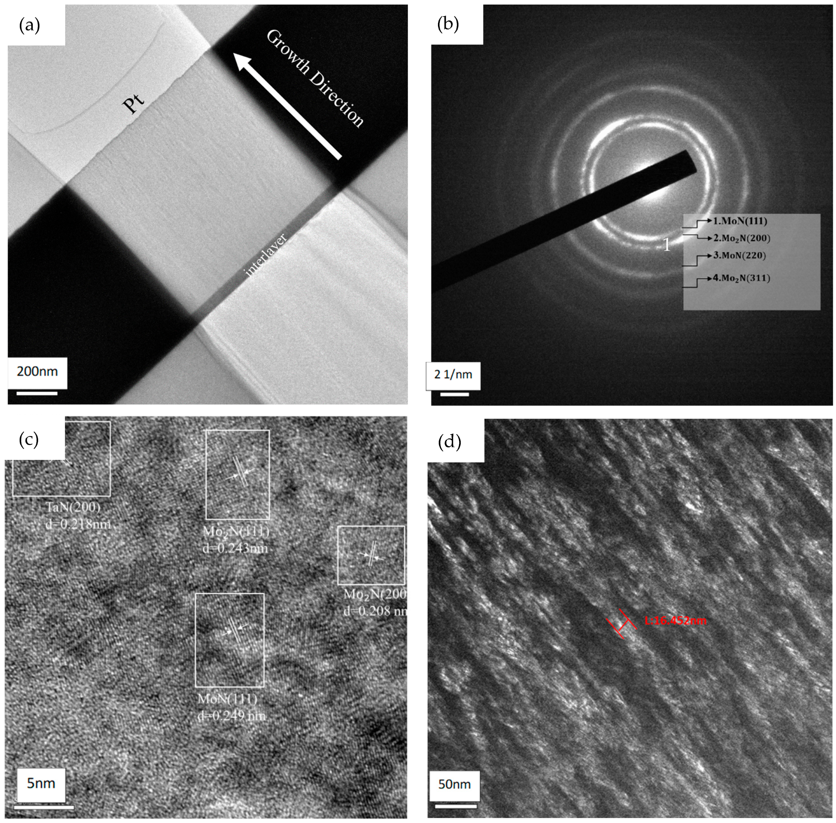
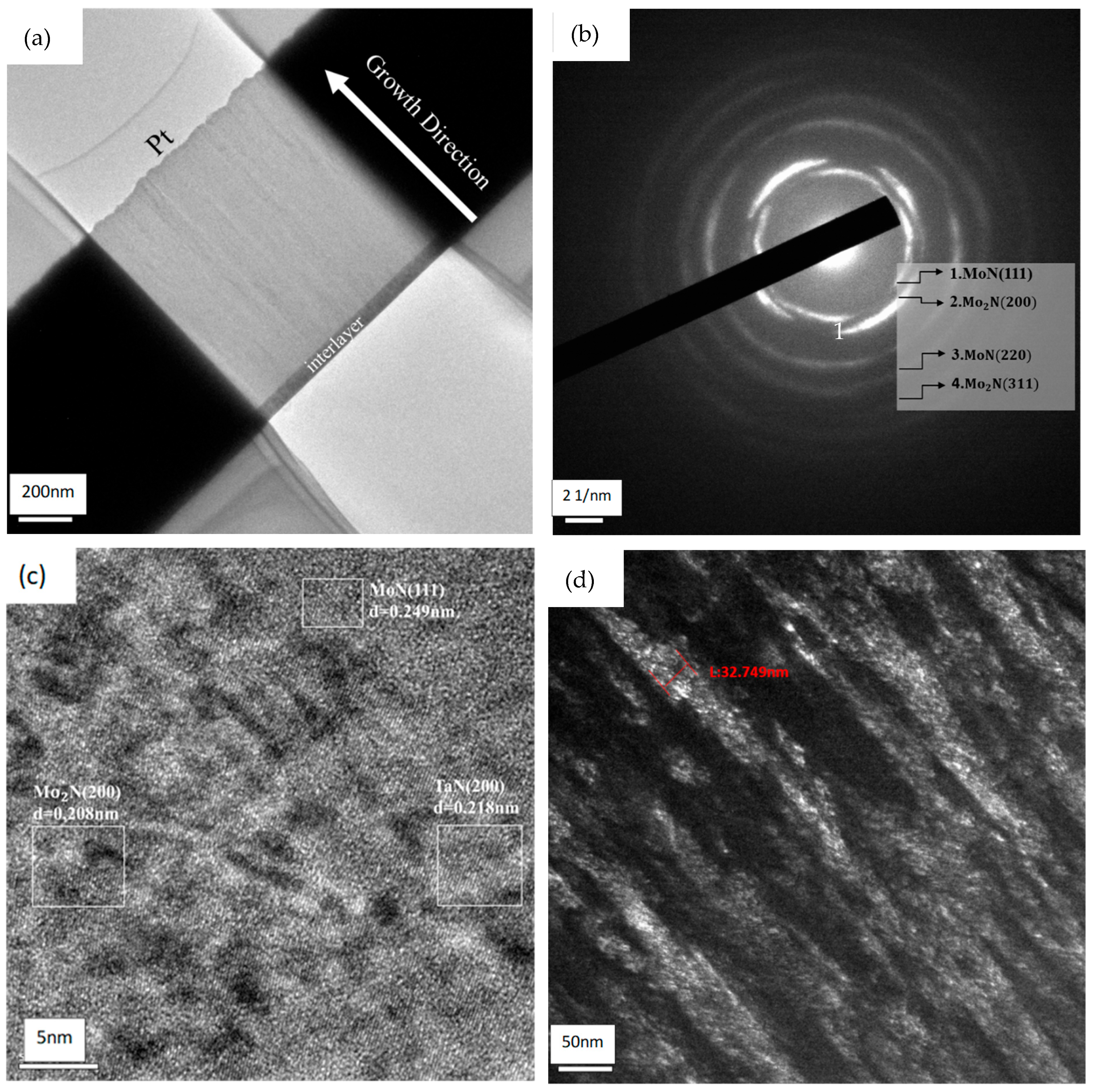
3.3. Identification of Nanostructure

In order to take an in-depth look into the microstructure of the MoTaN films, transmission electron microscopy was utilized to evaluate cross-sectional, high-resolution images, selected area diffraction, and dark-field images. Figure 4, Figure 5, Figure 6, Figure 7 and Figure 8 illustrate the microstructure of MoTaN layer samples B to F, respectively. In Figure 4a, Figure 5a, Figure 6a, Figure 7a and Figure 8a, cross-sectional images of the nitride coatings, including the interlayer and substrate, are demonstrated. All these MoTaN films basically showed a columnar crystalline structure along the film growth direction. The SAED patterns in Figure 4b, Figure 5b, Figure 6b, Figure 7b and Figure 8b for various MoTaN coatings, each display several continuous rings, implying a polycrystalline structure in the films. For sample B, the patterns were identified as (111) and (220) for the MoN phase and (200) and (331) for the Mo2N phase. Similar results are also found in the literature on MoN coatings [23,26]. In Figure 4c, the interplanar distances d = 0.249 nm for MoN(111), 0.208 nm for Mo2N(200), and 0.243 nm for Mo2N(111) were identified in the high-resolution TEM images of sample B. It should be noted that the TaN(200) phase was specified with an interplanar distance of 0.218 nm in the upper left corner of Figure 5c for sample C, meaning that TaN phase started to form in the MoTaN films. As the Ta content reached 10.4 at.% in sample D, not only were MoN(111) and Mo2N(200) identified, but also TaN(200), as illustrated in Figure 6c. This corresponds to the results from the X-ray diffraction data. Again, the 150/75 and 150/100 input power modulations, which could be taken as the transition region, exhibited sufficient energy and Ta incorporation in the MoTaN coatings and triggered the multiphase microstructure. With further incorporation of Ta through 150/125 and 150/150 input power modulations, the lattice spacings around 0.218 nm for TaN(200), 0.249 nm for MoN(111), and 0.208 nm for Mo2N(200) were specified in samples E and F, as shown in Figure 7c and Figure 8c, respectively. Dark-field imaging analysis of the MoTaN coatings was also conducted to determine the crystalline structure. Mo2N(200) was chosen as the target phase for comparison. As shown in Figure 4d, Figure 5d, Figure 6d, Figure 7d and Figure 8d, all MoTaN films exhibited a straightforward columnar structure along the growth direction. It is worth noting that the crystalline structure of Mo2N(200) evolved with the Ta contents. The Mo2N grain sizes of samples B, C, and D, presented a crystallographic structure smaller in diameter. The Mo2N(200) grain sizes of samples B to D, as indicated in Figure 4d, Figure 5d and Figure 6d, ranged from several to approximately 30 nm in diameter. On the other hand, when the input power modulation reached 150/125 and 150/150 with Ta additions of 13.9 and 16.8 at.% for samples E and F, respectively, the grain size of Mo2N(200) was over 30 nm. The higher energy resulting from the input power modulations of 150/125 and 150/150 W/W was beneficial for grain coarsening.

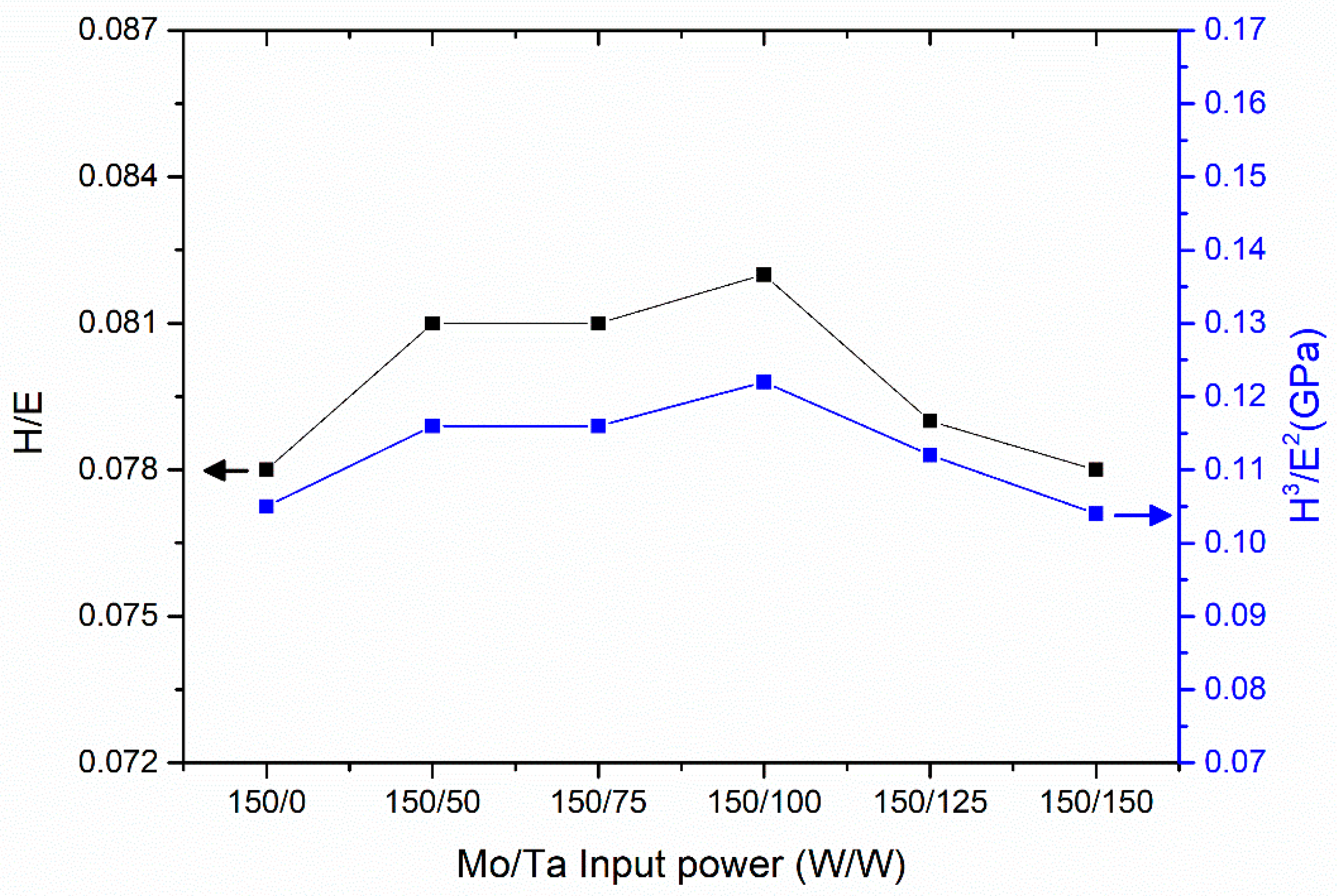
3.4. Mechanical Behavior

The hardness, H, reduced elastic modulus, E, and the ratios of H/E and H3/E2 of the MoTaN coatings are presented in Figure 9. The hardness of MoN was around 17.0 GPa [24]. The hardness of the MoTaN films ranged from 17.3 to 18.0 GPa. As the input power of the Ta was adjusted from 50 to 100 W, the hardness of the MoTaN samples increased slightly and gradually from 17.7 to 18.0 GPa. This slight improvement in hardness was due to the increased content of Ta from 3.7 to10.4 at.%, which formed multiple phases of MoN and TaN in the MoTaN films with a nanoscale grain size of several to 30 nm. With further strengthened input power modulation, the hardness of the MoTaN coatings decreased to 17.6 and 17.3 GPa for samples E and F, respectively. Meanwhile, the grain size of Mo2N(200) became broadened compared to that of samples B to D. As shown in Figure 7d and Figure 8d, grain sizes of 30 nm and above were observed for Mo2N(200) in samples E and F. The values of the reduced elastic modulus were 214–220 GPa for the various MoTaN coatings. The indices of H/E and H3/E2 are commonly used as a basis for the wear resistance of materials [27,28]. A shown in Figure 10, as the modulation increased, the values of H/E and H3/E2, like the trend in hardness, slightly increased and reached maximums of 0.082 and 0.122 GPa, respectively, at a modulation of 150/100. Then, the H/E and H3/E2 underwent gentle decreases, similar to the trend of hardness. In a recent work [19], the preferred orientation of δ-TaN(200) was discovered in reactively sputtered TaN films. The preferred orientation of (111) or (200) for fcc-TaN was observed, and the film’s hardness had a strong dependency on the phase. In the present study, a hard TaN phase formed in the MoTaN coatings as the input power modulation was enhanced to 150/75 and above. The hardness of the MoTaN rose indeed, yet the strengthening was not so significant since the primary phase in the MoTaN was the softer Mo2N. Nevertheless, in a study concerning a TaN-MoN coating system, similar trends in the H/E and H3/E2 were revealed [29]. In summary, with 3.7–10.4 at.% additions of Ta in the MoTaN coatings, a fine-grain effect was observed, enhancing the hardness. Simultaneously, the formation of TaN phase in the MoTaN films, contributing to a multiphase microstructure with Mo2N, could also provide a minor improvement in the mechanical characteristics.
The tribological behavior of MoTaN coatings was evaluated through a pin-on-substrate wear test, using a sliding pin mounted on an Al2O3 ball as a counterpart in a simple harmonic back-and-forth linear motion. The normal force and the total wear length were set as 3.2 N and 50 m, respectively. The surface morphology of the worn MoN and MoTaN samples after the wear tests is displayed in Figure 11. The surface morphology of the worn MoN coating in Figure 11a reveals several darker damaged region, along with severe scratches. When the content of Ta was 3.7 at.%, some dark damaged areas and scars, due to the scratching from the alumina oxide ball, could still been observed, as shown in Figure 11b. As compared with the MoN film, the small amount of 3.7 at.% Ta in the MoTaN showed slightly enhanced hardness, H/E, and H3/E2, with evidence that the enhanced anti-wear phenomenon avoided severe scratching. The trend of wear resistance can be predicted from the indices of H/E and H3/E2. Better wear-resistant properties are generally accompanied by a higher index [27,28]. The optimized anti-wear characteristic of the MoTaN films was obtained for the films with a Ta addition range of 6.8–10.4 at.%, i.e., samples C and D. No significant deep scars were found, and only a limited and small chipping area was seen, as shown in Figure 11c,d. Likewise, the hardness, H/E, and H3/E2 kept rising to their maximum values for the MoTaN layers, and the coatings showed relatively better wear resistance than the other samples. It can also be argued that the multiphase structure of Mo2N and TaN and the refined grain size of less than 30 nm were both beneficial for the anti-wear properties of the MoTaN films. In contrast, sample E had some dark damaged areas due to the enlargement of the grain size in phase Mo2N(200) over 30 nm. Sample F presented the worst mechanical properties among all of the MoTaN films. The grain size of the Mo2N(200) phase was frequently over 30 nm, and the H/E and H3/E2 decreased to relatively low values of 0.078 and 0.104 GPa, respectively. Consequently, the MoTaN coatings with Ta higher than 13.9 at.% demonstrated an inferior wear-resistance property.
In summary, the addition of Ta to the MoTaN films with the modulation of input power showed a monotonic proportional relationship. The MoTaN films with Ta incorporation from 3.7 to 16.8 at.%, through nanoindentation analysis, showed hardness and elastic modulus values ranging from 17.0 to 18.0 GPa and from 213.8 to 220.7 GPa, respectively. There were no significant differences among the samples. Nevertheless, a maximum hardness of 18.0 GPa and resultant superior H/E and H3/E2 values were observed at an Mo/Ta input power of 150/100 W/W. The calculated H3/E2 values indicate improved wear resistance, as illustrated in Figure 11. In comparison to the MoN film, the MoTaN coating exhibited superior mechanical properties, attributed to its multiphase structure and fine columnar grain size. The MoTaN thin films were developed to enhance performance for protective applications, aiming to elongate the lifetime and strengthen the surface properties of materials of interest, in consideration of sustainability. The effect of the input power during deposition plays a critical role in determining the overall performance of MoTaN co-sputtering coatings.

4. Conclusions

MoTaN films were manufactured through reactive r.f. magnetron co-sputtering, and their microstructure and mechanical characteristics were investigated. Changes in the input power modulation of Mo/Ta affected the Ta incorporation, microstructure, and mechanical properties, including the hardness, elastic modulus, H/E, H3/E2, and anti-wear performance of the MoTaN coatings. As the Ta contents in the MoTaN films increased with the input power on the Ta target during processing, the deposition rate rose from 5.4 to 6.7 nm/min, and the ratios of (Mo + Ta)/N were stable at 1.0, regardless of the input power modulation. Stable nitride formation occurred in the co-sputtering process. The addition of Ta resulted in a multiphase microstructure, featuring Mo2N and TaN phases. With 3.7 to 10.4 at.% of Ta, the MoTaN films comprised a refined columnar grain with a size of less than 30 nm. Better anti-wear performance was found for the MoTaN fabricated with an input power modulation of Mo/Ta at 150/100 W/W and a resultant Ta content of 10.4 at.%. The improvement in the mechanical characteristics of the MoTaN co-sputtering coatings was attributed to their multiphase and fine-grain structure.

Author Contributions

Conceptualization, J.-Y.H. and F.-B.W.; methodology, J.-Y.H. and F.-B.W.; software, J.-Y.H.; validation, J.-Y.H. and F.-B.W.; formal analysis, J.-Y.H.; investigation, J.-Y.H.; resources, F.-B.W.; data curation, J.-Y.H.; writing—original draft preparation, J.-Y.H.; writing—review and editing, F.-B.W.; visualization, J.-Y.H. and F.-B.W.; supervision, F.-B.W.; funding acquisition, F.-B.W. All authors have read and agreed to the published version of the manuscript.

Funding

The financial support from the National Science and Technology Council, NSTC, in Taiwan, with contract nos. NSTC 112-2221-E-239-010 and NSTC 112-2622-E-239-003.

Institutional Review Board Statement

Not applicable.

Informed Consent Statement

Not applicable.

Data Availability Statement

Data is contained within the article.

Conflicts of Interest

The authors declare no conflict of interest.

References

  1. Kommer, M.; Sube, T.; Richter, A.; Fenker, M.; Schulz, W.; Hader, B.; Albrecht, J. Enhanced wear resistance of molybdenum nitride coatings deposited by high power impulse magnetron sputtering by using micropatterned surfaces. Surf. Coat. Technol. 2018, 333, 1–12. [Google Scholar] [CrossRef]
  2. Lee, G.R.; Kim, H.; Choi, H.S.; Lee, J.J. Superhard tantalum-nitride films formed by inductively coupled plasma-assisted. Surf. Coat. Technol. 2007, 201, 5207–5210. [Google Scholar] [CrossRef]
  3. Luo, Q.; Lu, C.C.; Liu, L.G.; Zhu, M.Y. A review on the synthesis of transition metal nitride nanostructures and their energy related applications. Green Energy Environ. 2023, 8, 406–437. [Google Scholar] [CrossRef]
  4. Guo, H.J.; Chen, W.Y.; Shan, Y.; Wang, W.Z.; Zhang, Z.Y.; Jia, J.H. Microstructures and properties of titanium nitride films prepared by pulsed laser deposition at different substrate temperatures. Appl. Surf. Sci. 2015, 357, 473–478. [Google Scholar] [CrossRef]
  5. Wang, J.; Munroe, P.; Zhou, Z.F.; Xie, Z.H. Nanostructured molybdenum nitride-based coatings: Effect of nitrogen concentration on microstructure and mechanical properties. Thin Solid Films 2019, 682, 82–92. [Google Scholar] [CrossRef]
  6. Benkahoul, M.; Martinez, E.; Karimi, A.; Sanjinés, R.; Lévy, F. Structural and mechanical properties of sputtered cubic and hexagonal NbNx thin films. Surf. Coat. Technol. 2004, 180–181, 178–183. [Google Scholar] [CrossRef]
  7. Samano, E.C.; Clemente, A.; Díaz, J.A.; Soto, G. Mechanical properties optimization of tungsten nitride thin films grown by reactive sputtering and laser ablation. Vacuum 2010, 85, 69–77. [Google Scholar] [CrossRef]
  8. Larijani, M.M.; Tabrizi, N.; Norouzian, S.; Jafari, A.; Lahouti, S.; Hosseini, H.H.; Afshari N, N. Structural and mechanical properties of ZrN films prepared by ion beam sputtering with varying N2/Ar ratio and substrate temperature. Vacuum 2006, 81, 550–555. [Google Scholar] [CrossRef]
  9. Bernoulli, D.; Müller, U.; Schwarzenberger, M.; Hauert, R.; Spolenak, R. Magnetron sputter deposited tantalum and tantalum nitride thin films: An analysis of phase, hardness and composition. Thin Solid Films 2013, 548, 157–161. [Google Scholar] [CrossRef]
  10. Liu, Q.; Fang, Q.F.; Liang, F.J.; Wang, J.X.; Yang, C. Synthesis and properties of nanocomposite MoSiN hard films. Surf. Coat. Technol. 2006, 201, 1894–1898. [Google Scholar] [CrossRef]
  11. Bian, S.H.; Xu, J.H.; Yu, L.H.; Wang, P.K.; Jiang, Y.H.; Chen, C.Y. Structure regulation and property correlation of Hf-B-N thin films. Ceram. Int. 2023, 49, 25743–25758. [Google Scholar] [CrossRef]
  12. Gilewicz, A.; Jedrzejewski, R.; Kochmanska, A.E.; Warcholinski, B. Structure of MoCN films deposited by cathodic arc evaporation. Thin Solid Films 2015, 577, 94–96. [Google Scholar] [CrossRef]
  13. Neumann, S.; Wüstefeld, C.; Motylenko, M.; Haus, L.; Bräunig, S.; Müller, M.; Rafaja, D. Microstructure and thermal stability of Mo-(Ag)-N coatings with high nitrogen content. Surf. Coat. Technol. 2018, 352, 257–264. [Google Scholar] [CrossRef]
  14. Wang, W.Z.; Zheng, S.X.; Pu, J.B.; Cai, Z.B.; Wang, H.X.; Wang, L.P.; He, G.G. Microstructure, mechanical and tribological properties of Mo-V-N films by reactive magnetron sputtering. Surf. Coat. Technol. 2020, 387, 125532. [Google Scholar] [CrossRef]
  15. Mei, H.J.; Ding, J.C.; Wang, R.; Li, Q.G.; Zhao, Z.T.; Long, D.F.; Wei, X.H.; Cai, S.Q.; Gong, W.P.; Wang, Q.M. Relationship between oxidation behavior and tribological properties of MoVCuN coatings. Surf. Coat. Technol. 2022, 451, 129067. [Google Scholar] [CrossRef]
  16. Xiang, J.Y.; Lin, Z.X.; Renoux, E.; Wu, F.B. Microstructure evolution and indentation cracking behavior of MoN multilayer films. Surf. Coat. Technol. 2018, 350, 1020–1027. [Google Scholar] [CrossRef]
  17. Suszko, T.; Gulbiński, W.; Jagielski, J. The role of surface oxidation in friction processes on molybdenum nitride thin films. Surf. Coat. Technol. 2005, 194, 319–324. [Google Scholar] [CrossRef]
  18. Liu, C.K.; Ju, H.G.; Xu, J.H.; Yu, L.H.; Zhao, Z.T.; Geng, Y.X.; Zhao, Y. Influence of copper on the compositions, microstructure and room and elevated temperature tribological properties of the molybdenum nitride film. Surf. Coat. Technol. 2020, 395, 125811. [Google Scholar] [CrossRef]
  19. Tan, P.; Fu, L.C.; Teng, J.; Zhu, J.J.; Yang, W.L.; Li, D.Y.; Zhou, L.P. Effect of texture on wear resistance of tantalum nitride film. Tribol. Int. 2019, 133, 126–135. [Google Scholar] [CrossRef]
  20. Li, H.; Li, J.L.; Kong, J.; Huang, J.W.; Wu, Q.J.; Xiong, D.S. Hard and tough sub-stoichiometric B1 Ta-Mo-Nx films by regulating N content. J. Alloys Compd. 2023, 934, 168009. [Google Scholar] [CrossRef]
  21. Qin, H.; Tao, Y.; Deng, B. Microstructural and mechanical properties of Si-ion implanted TiN coatings. Surf. Coat. Technol. 2013, 228, 292. [Google Scholar] [CrossRef]
  22. Wang, L.P.; Zhang, G.G.; Wood, R.J.K.; Wang, S.C.; Xue, Q.J. Fabrication of CrAlN nanocomposite films with high hardness and excellent anti-wear performance for gear application. Surf. Coat. Technol. 2010, 204, 3517. [Google Scholar] [CrossRef]
  23. Liao, Y.H.; Wu, F.B. Microstructure evolution and mechanical properties of refractory molybdenum-tungsten nitride coatings. Surf. Coat. Technol. 2024, 476, 130154. [Google Scholar] [CrossRef]
  24. Wasa, K.; Kanno, I.; Kotera, H. Handbook of Sputtering Technology, 2nd ed.; William Andrew Publication: Norwich, NY, USA, 2012; pp. 45–75. [Google Scholar]
  25. Lee, W.H.; Lin, J.C.; Lee, C.P. Characterization of tantalum nitride films deposited by reactive sputtering of Ta in N2/Ar gas mixtures. Mater. Chem. Phys. 2001, 68, 266–271. [Google Scholar] [CrossRef]
  26. Jiang, Y.H.; Wu, X.M.; Yu, L.H.; Chen, C.Y.; Han, H.W.; Bian, S.N.; Zuo, B.; Zhao, L.J.; Xu, J.H. In-situ Tribo-induced Formation of Superb Lubricious Carbon-based Tribofilms on the Catalytical Active MoN-Ag film surfaces. Tribol. Int. 2024, 196, 109715. [Google Scholar] [CrossRef]
  27. Leyland, A.; Matthews, A. On the significance of the H/E ratio in wear control: A nanocomposite coating approach to optimised tribological behavior. Wear 2002, 246, 1–11. [Google Scholar] [CrossRef]
  28. Beake, B.D. The influence of the H/E ratio on wear resistance of coating systems—Insights from small-scale testing. Surf. Coat. Technol. 2022, 442, 128272. [Google Scholar] [CrossRef]
  29. Klimashin, F.F.; Lobmaier, L.; Koutná, N.; Holec, D.; Mayrhofer, P.H. The MoN–TaN system: Role of vacancies in phase stability and mechanical properties. Mater. Des. 2021, 202, 109568. [Google Scholar] [CrossRef]
Figure 1. The composition of the MoTaN coatings as a function of input power modulation.
Coatings 15 00080 g001
Figure 2. The Ta/(Mo + Ta) ratio as a function of input power modulation.
Coatings 15 00080 g002
Figure 3. The X-ray diffraction patterns for MoN [23] and various MoTaN coatings.
Coatings 15 00080 g003
Figure 4. TEM of sample B: (a) cross-sectional image, (b) SAED, (c) HR image, and (d) dark-field image of point 1 in (b).
Coatings 15 00080 g004
Figure 5. TEM of sample C: (a) cross-sectional image, (b) SAED, (c) HR-TEM image, and (d) dark-field image of point 1 in (b).
Coatings 15 00080 g005
Figure 6. TEM of sample D: (a) cross-sectional image, (b) SAED, (c) HR-TEM image, and (d) dark-field image of point 1 in (b).
Coatings 15 00080 g006
Figure 7. TEM of sample E: (a) cross-sectional image, (b) SAED, (c) HR-TEM image, and (d) dark-field image of point 1 in (b).
Coatings 15 00080 g007
Figure 8. TEM of sample F: (a) cross-sectional image, (b) SAED, (c) HR-TEM image, and (d) dark-field image of point 1 in (b).
Coatings 15 00080 g008
Figure 9. The hardness, reduced elastic modulus, H/E, and H3/E2 of the MoN [28] and MoTaN coatings.
Coatings 15 00080 g009
Figure 10. The H/E and H3/E2 as a function of the Mo/Ta input power modulation for the MoN [28] and MoTaN coatings.
Coatings 15 00080 g010
Figure 11. The morphology of wear scars on the MoN [29] and MoTaN films: (a) A, (b) B, (c) C, (d) D, (e) E, and (f) F.
Coatings 15 00080 g011
Table 1. The input power modulation, composition, elemental ratios, and deposition rate, of the MoN [23] and MoTaN films.
Sample
Designation
Input Power (W)
(Mo/Ta)
Composition (at.%)Elemental RatioDeposition
Rate
(nm/min)
MoTaNMo/TaTa/(Mo + Ta)(Mo + Ta)/N
A150/0 45.7   ± 0.6 0 54.4   ± 0.7-00.854.4
B150/50 46.4   ± 0.8 3.7   ± 0.2 49.8   ± 0.912.60.071.005.4
C150/75 42.5   ± 0.5 6.8   ± 0.2 50.6   ± 0.5 6.30.130.975.6
D150/100 41.0   ± 0.5 10.4   ± 0.3 48.6   ± 0.83.90.201.065.8
E150/125 36.2   ± 0.5 13.9   ± 0.3 50.0   ± 082.60.281.006.5
F150/150 34.5   ± 0.2 16.8   ± 0.1 48.7   ± 0.32.10.331.056.7
Disclaimer/Publisher’s Note: The statements, opinions and data contained in all publications are solely those of the individual author(s) and contributor(s) and not of MDPI and/or the editor(s). MDPI and/or the editor(s) disclaim responsibility for any injury to people or property resulting from any ideas, methods, instructions or products referred to in the content.

