Article

An Evaluation of the Microstructure and Hardness of Co-Rich PTA Overlays on a Duplex Steel Substrate

Faculty of Materials Engineering and Industrial Computer Science, AGH University of Science and Technology in Krakow, al. Mickiewicza 30, 30-059 Kraków, Poland
Coatings 2025, 15(1), 69; https://doi.org/10.3390/coatings15010069
Submission received: 17 December 2024 / Revised: 24 December 2024 / Accepted: 8 January 2025 / Published: 10 January 2025
(This article belongs to the Section Plasma Coatings, Surfaces & Interfaces)

Abstract

:
Overlaying welding is a technology that allows for the acquisition of structural materials with advantageous and complex operating properties. The substrate material can be a material with advantageous mechanical and plastic properties, and the coating can provide corrosion or abrasion (wear) resistance. Among coating application techniques, plasma transfer arc (PTA) overlay welding can be used, where the overlay ensures metallic continuity and high durability, but is a limitation in the joining technologies. Therefore, research was carried out on the possibility of making Co-rich PTA overlay welding coatings on duplex steel, which combine the unique properties of duplex steel and the abrasion resistance of the coating. The tests performed showed that it is possible to apply a coating on the edges of elements without unfavorable changes in the material associated with the formation of carbides and the sigma phase in the HAZ. The coating has a structure of a Co-rich solid solution and a net of eutectics with carbide precipitations. This allowed for high hardness (600 HV10) without the need for additional heat treatment procedures.

1. Introduction

The surface modification of steel products plays an important role in obtaining favorable operating properties of machine parts operated under unfavorable conditions. Unfavorable conditions can be the effect of the corrosive environment, abrasion, or dynamic loads and lead to rapid wear or failure [1]. Therefore, coatings allow for the reduction of manufacturing costs by using a substrate with lower mechanical and plastic properties together with coating properties appropriate for direct contact with the operation environment [2,3]. Depending on the purpose, coatings can be a thermal barrier and then made of ceramic materials or dynamic loads from plastic materials. In the case of high loads, significant plasticity of the coating is required to avoid cracking. For abrasion resistance, the criterion is the hardness of the coating or its abrasion resistance. Hence, coatings (sprayed or cladded) have different shapes and natures, which are determined by their purpose. They can be made as layers welded from wire, sheets, explosively welded, or powder. The use of powders is becoming the most common method due to the relatively easy preparation of the material for coating [4]. These powders are most often made using nickel or cobalt as a matrix and reinforced by the addition of WC, TiC, Cr3C2, VC, BN, TiB2, or diamond particles.
Among coating methods, flame spraying, thermal spraying, laser metal cladding (LBC or LBW-F), plasma spray coating, or powder plasma-transferred arc (PTA or PAW) coating techniques are available [5]. These techniques allow for the production of coatings on any substrate, from unalloyed steel through micro-alloyed and alloyed steel and other alloys. To produce a coating, it is important that the surface is properly prepared (appropriate roughness and cleanliness) and insensitive to the heat input process [6,7]. As a result of the process, the coating is bonded to the substrate, but fusion does not occur. In the case of spraying, it is not necessary to use materials capable of creating solid solutions. Then, the problem may be the lack of metallurgical fusion (only adhesion) in the bonding area, where the powder is only partially melted (not completely melted). The surfaces of the particles may be partially oxidized too, which limits their ability to bond. On the other hand, porosity and poor adhesion to the substrate can occur, affecting the detachment of the coating, especially with heavy loads [8,9].
In the case of cladding or overlaying welding, the powder and the surface layer melt and mix in the fusion area. Therefore, these materials must have similar metallurgical properties, and a mixing layer is formed at the boundary (transition layer) [10]. These coatings show lower porosity and favorable adhesion to the substrate, and in the case of similar thermal expansion coefficients, there are also no cracks [11]. Therefore, the formation of a transition layer requires the use of more than one layer to avoid mixing with the substrate, in particular the use of corrosion resistant coatings on non-alloy steels with a low Fe content on the coating surface [12]. Typical welding techniques that use solid or flux wire [13] as filler material are successfully used—for example, using CMT (Cold Metal Transfer Cladding) [14] or TIG (Tungsten Inert Gas Cladding) [15,16] or using wire or powder in the LBW-F (Laser Beam Cladding) [3,17,18] or PAW (plasma arc cladding) [19,20,21] process. The advantage of plasma arc cladding is better control of the liquid metal and fewer defects, such as pores or cracks, as well as a more favorable structure. The dominant clad materials are austenitic steels [22,23], duplex [24], and Ni-rich alloys [25,26] as well as titanium alloys [27]. Multicomponent Co-rich alloys [28] are gaining importance. In Co-rich alloys, the structure of the matrix and the eutectics of Co are observed, with precipitations of various types of carbides in the microstructure [29,30]. These coatings can obtain different properties depending on the method of their production and crystallization as well as the heat treatment performed. This indicates that if the required properties are not obtained during the production of the coating, further processes cannot be carried out due to the properties of the substrate material. An example is the pair of duplex steel on the substrate and the Co-rich coating. The substrate steel is sensitive to heat input, which causes changes in the structure and the separation of unfavorable phases, while the Co-rich coating requires aging; hence, it is mainly performed as a sprayed coating. In this work, an attempt was made to obtain a coating by overlay welding with a microstructure and hardness in the post-process state without the need for additional heat treatment.
Powder Plasma Transferred Arc (PTA) process based on a plasma beam as a result of an electric discharge inside the plasma torch. The high temperature of the arc and the potential difference between the tungsten cathode and the plasma nozzle cause the ionization of the plasma gas (most often, argon or rare helium). Powder is transported with the plasma gas, which melts due to the high temperature. Liquid drops of powder are transferred to the metal surface, creating a pool of liquid metal (weld pool). The heat of the arc also causes partial melting of the metal surface, thus mixing the substrate and powder materials at the boundary of the metal and the pool [19,21]. Therefore, it is crucial for making coatings (overlay or cladding) to obtain the narrowest mixing area (transition layer). At the same time, in the case of coatings with a different chemical composition than the substrate, it is important to avoid mixing in the entire volume of the overlay weld. Hence, coatings are most often made as a two-layer overlay weld [10].
Tungsten carbides (WC) provide excellent resistance to abrasion [31]. However, WCs are prone to dissolution under high heat input conditions in the melt pool generated during cladding [32]. The carbides’ dissolution occurs in the case of plasma arc cladding and laser cladding [33]. High heat input and slow solidification of the clad metal promote the formation of a coarse crystalline structure, where crystallite grows from the substrate, and the nickel filler material promotes the formation of hot cracks. Based on the work of Yoon et al. [34] and DuPont [35], the reason is the presence of eutectics. In the transition zone between the clad and substrate, a transition structure is formed as a result of the mixing of both materials. Depending on the meta of the substrate, a hardened zone in unalloyed steels and an area for hydrogen embrittlement may form [36,37]. In the case of heat-treated steels, a softening zone can also occur in the steels after heat treatment [38,39].
In the case of 304 austenitic steel coatings on a non-alloy steel substrate, both hard martensite and susceptibility to stress sulfide corrosion cracking (SSCC) may occur. Duplex steels, in high temperatures, are prone to precipitation of brittle intermetallic phases and carbides [40]. This indicates that the structure of the clads is mostly dependent on the technique used for production, but there is a lack of a description of the structure of clads produced on different substrates. Thus, the growing demand for machine elements with favorable properties, in terms of wear resistance necessitates, shows the need for further microstructural studies. In particular, it is important to know the structure of clads produced using Ni-base and Co-base powders reinforced by carbides as well as to describe the mechanical properties and hardness together with structural analysis. To meet these needs, plasma arc overlay welding tests were performed on a 2205 duplex steel substrate, which was subjected to material tests, including a microstructure analysis and hardness measurements. The research carried out complements the knowledge in the field of manufacturing wear-resistant clads and can be directly applied in practice.

2. Materials and Methods

The samples for the tests were coatings made by plasma transferred arc (PTA) overlay welding. The substrate was duplex steel X2CrNiMoN22-5-3 (ANSI 2205, 1.4462) with a thickness of 8 mm and a chemical composition shown in Table 1 (acc. to material certificate). The coatings were made 190 mm with an arc at the edge of the sheet to limit the amount of heat input to the material and to avoid straightness of the overlay. The method of making the coatings resulted from the practical application of coatings, where the most common areas to be cladded are the edges or the surface close to the edges, which are subject to significant abrasion. The commercial powder Eutalloy® Cobaltec 10092 (Castolin Europe GmbH, Bad Soden, Germany), with a chemical composition that is shown in Table 2 (according to the manufacturer’s certificate), was used to make the coating. Cladding was carried out using a station equipped with Eutronic GAP 3001 (Castolin, Kriftel, Germany) and a Multi-Surfacer D2 Weld automatic welding machine (Welding Alloys, Cambridge, United Kingdom). Overlay welding tests were carried out to obtain the correct shape of the overlay welds. The criterion was a uniform overlay weld face along the entire length without visible powder residue. The best results were obtained using the following parameters: welding current 70 A, voltage 28.4 V, cladding rate 150 mm/min (2.5 mm/s), plasma gas flow rate (Ar) 4–5 L/min, shielding gas flow rate (Ar) 8.0–8.5 L/min, and a distance between material and nozzle of 9 mm. Five samples were made with these parameters and tested. The powder feeding rate was 50 ± 3 g/min. Table 1 and Table 2 indicate the chemical compositions of the materials used to make the samples.
The clads were subjected to penetration tests to reveal surface cracks. Penetration testing was performed in accordance with EN ISO 3452-1 standard [41]. Before testing, the surface was thoroughly washed with acetone. The penetrant was sprayed for 10 min, then excess penetrant was removed from the surface using paper, and a developer was sprayed. Examination did not reveal any cracks (Figure 1b). To reveal the structure and hardness measurements, the samples were cut in cross-section using a metallographic cutting machine with intensive water cooling and embedded in epoxy resin. The surfaces of the cross-sections were subjected to grinding on water-based abrasive papers and polished using diamond suspension and polishing cloth. Electrochemical etching was used to reveal the structure using a 10% aqueous solution of chromium (VI) oxide and a 20% aqueous solution of sodium hydroxide.
Microstructure observations were performed using light microscopy (Leica Streozoom 9i, Leica Microsystems, Heerbrugg, Switzerland and Leica LM/DM, Leica, Wetzlar, Germany) and scanning electron microscopy (Hitachi S-3500N, Hitachi Ltd., Tokyo, Japan) equipped with the energy dispersive spectroscopy (EDS) system. Powder observations were made using scanning electron microscope (SEM).
Hardness measurements were performed in cross-section using a Zwick Roel ZHU 185 (Zwick Roell Group, Ulm, Germany) hardness tester using the Vickers method. The intender load was 98.1 N in 10 s. Measurements were made in 4 separates lines in every cross sections. Measurements were performed in measuring lines that covered the overlay and substrate area.

3. Results

3.1. Powder Charakterization

The powder particle morphology was evaluated using SEM observation. The powder image is presented in Figure 1a. The powder particle has a spherical shape morphology. In the powder mixture, we observed small and greater particles, where the larger particles are mostly present and the smaller are bonded with the larger. The diameter of the particles is between 50 μm and 80 μm. The EDS analysis showed that Co and Ni are the main elements of the powder, and there is a lack of WC particles (Figure 1b). The shape of the particle can indicate the high toughness of the overlay. Furthermore, the shape of the powder particles allow for a stable powder feed rate to be reached and avoiding the blocking effect in the nozzle.

3.2. Surface Morphology

Visual testing shows that the overlay is characterized by a uniform surface along its entire length (Figure 2a). The width of the overlay is 19.5 ± 0.5 mm. The smooth surface of the overlay is visible. On the substrate side, small amounts of powder residues were observed, which are bonded to the surface. The steel surface is free from contamination.
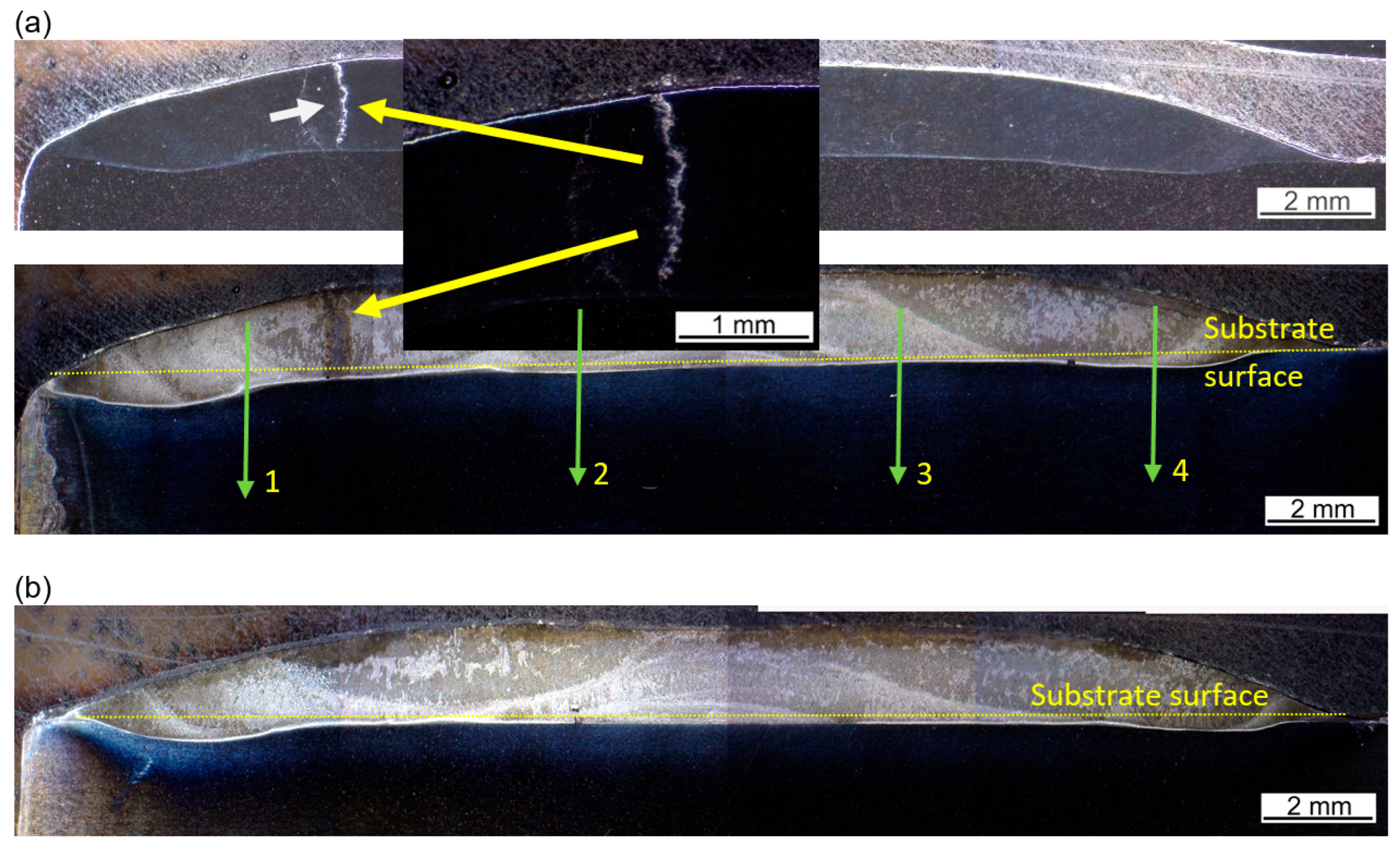
Penetrant testing (PT) did not show the occurrence of transverse cracks and a network of cracks (Figure 2b). In one sample, a longitudinal crack was observed with a length of less than 10 mm. The metallographic cross-section revealed that the crack covers the entire thickness of the coating (Figure 3a). The thickness of the coating is in the range of 1.5 ± 0.05 mm and decreases gently as it approaches the edge. In all tests, the thickness of the five tested coatings was obtained in the range of 1.6 ± 0.1 mm, indicating the correctness of the selected process parameters and its high repeatability. In the area at the edges, a greater fusion into the substrate material is also observed, reaching up to 0.3 mm (Figure 3b). This indicates that heat is concentrated directly at the edge, and an increased mixing with the substrate material occurs. In the remaining areas, the fusion into the substrate material does not exceed 0.1 mm.

3.3. Microstructure Evaluation of Substrete Material

The tests of the base material performed in the cross-section showed a ferritic–austenitic structure. The ferrite (δ) and austenite (γ) grains are elongated in the direction the sheet was rolled. The width of the bands is regular throughout the sheet cross-section. Precipitations of carbides or other intermetallic phases were not revealed within the grain boundaries (Figure 4).

3.4. Microstructure Evaluation of Transition Zone

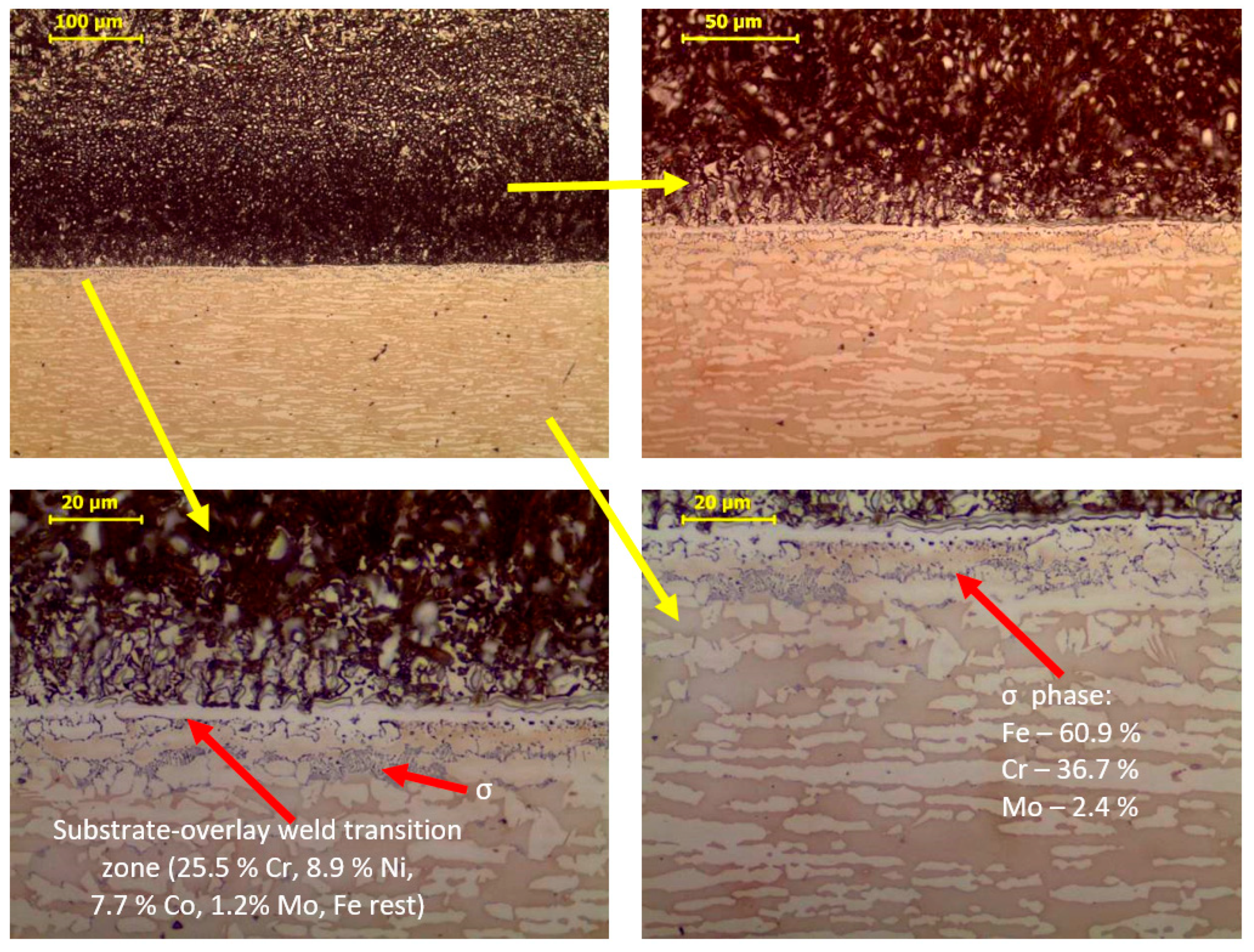
As a result of the overlay welding heat input, small amounts of precipitates appeared near to the fusion line in the heat affected zone (HAZ). Precipitations occur mainly in the δ-ferrite area, which indicates that they constitute the σ intermetallic phase (Figure 5). The σ phase consists mainly of Fe and Cr, and Mo may also be present in it. The increase in Cr content in ferrite promotes its formation. At temperatures in the range of 600–900 °C, the δ-ferrite decomposes into the σ phase and austenite according to the reaction:
Ferrite δ → σ phase + Austenite γ.
The revealed σ precipitations do not form a continuous band of precipitations and constitute an area with a width of 5–10 μm, which ensures that the plasticity of the steel is not reduced, and consequently, the welded layer will not detach. As a result of the heat effect in the overlay welding in the HAZ, a slight grain growth occurred, covering two grain thicknesses, and there was a change in the δ-ferrite morphology. The partially plate-like structure of the ferrite indicates a slight overheating of the steel. The change in ferrite morphology is typical of the HAZ in duplex steel.
Changes in the morphology of the structure in the HAZ can reach up to 1 mm below the fusion line. On the overlay weld side, on the fusion line, a narrow transition zone is observed. The width of the transition zone is below 10 μm. In this area, the substrate material and the overlay weld material were mixed, as indicated by the content of Fe, Ni, and Co (Figure 5). The presence of this layer ensures good adhesion of the coating to the substrate. This area is characterized by a dendritic structure with visible Co-rich and carbide eutectics. In the structure at the fusion line, small amounts of gas voids are visible (Figure 6). Gas voids can be seen as flaws and potential future cracks.

3.5. Microstructure Evaluation of Overlay Weld

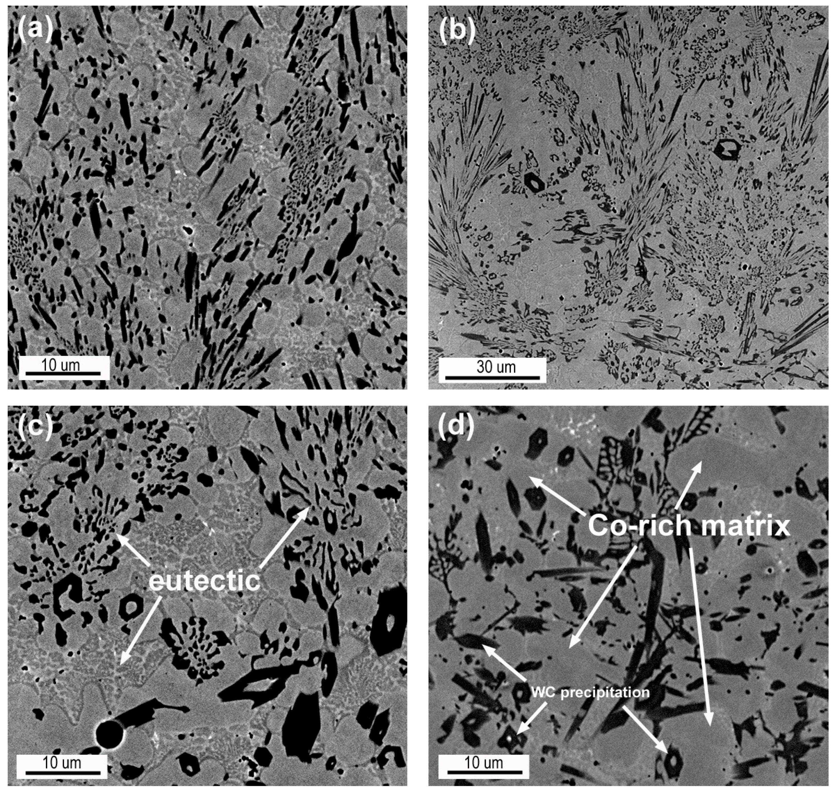
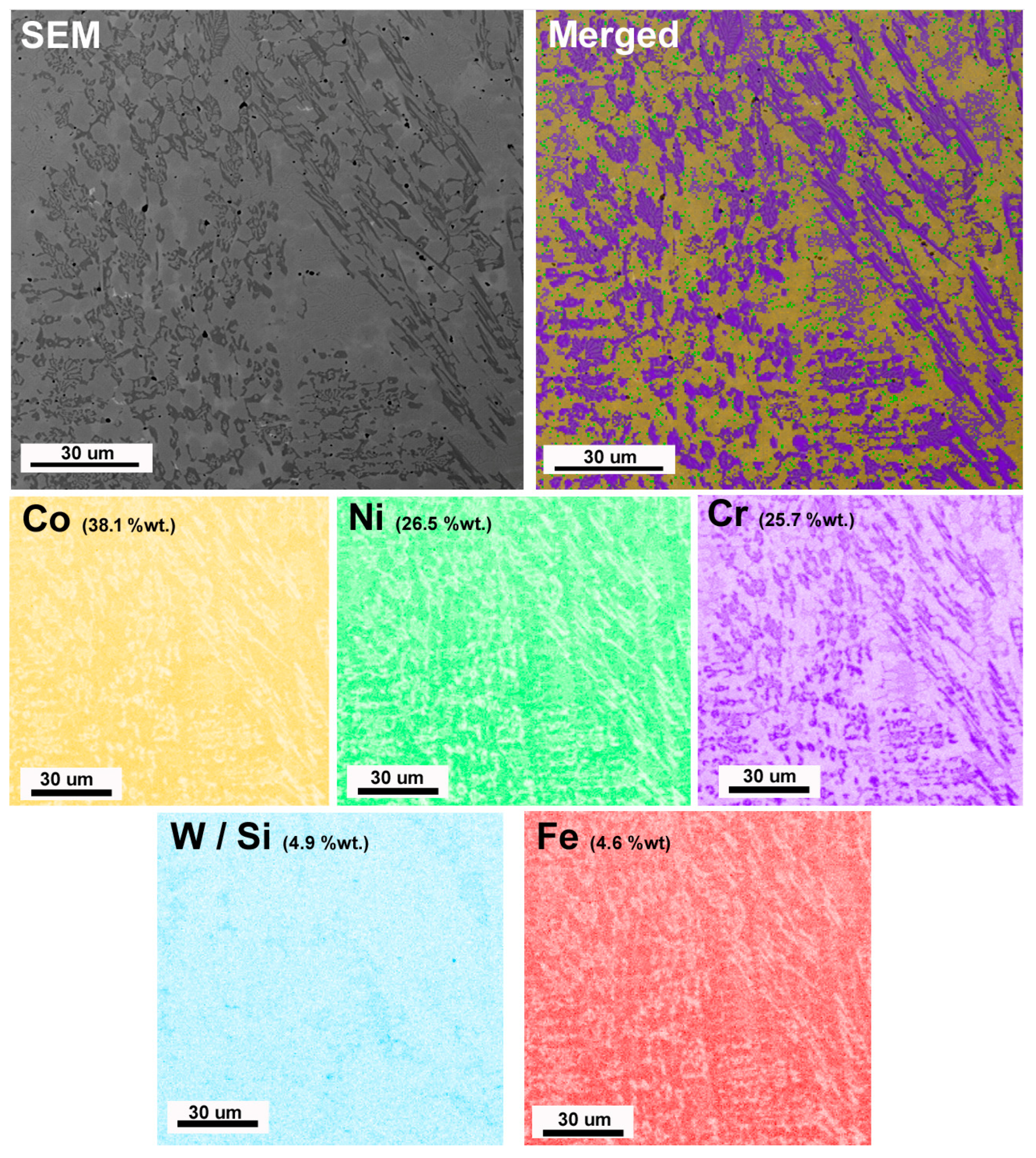
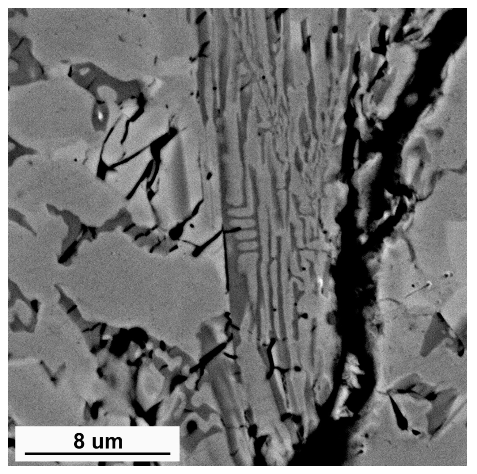
The overlay weld is characterized by a complex dendritic structure, where solid solution dendrites of cobalt-base (fcc γ-Co or hcp ε-Co [42]) and eutectic structures can be observed with a large number of small precipitates of carbides rich in Cr, Si, Ni, Co, and W (Figure 7 and Figure 8). Massive precipitates of tungsten carbides (WC or W2C), chromium carbides (Cr7C3), (Cr,Co,W,Ni)23C6, boride silicate eutectics, and intermetallic phases (Co3W) [43]. (Figure 8). The precipitates of carbides melted due to the heat of the plasma arc and assumed a globular shape, but the plate-like structure is dominant after crystallization. This indicates that the structure was formed during the crystallization of the melted powder. The uniform distribution of chromium (Figure 8) indicates that the precipitation of chromium carbides can occur from a supersaturated solid solution. The presence of dissolved elements caused the formation of eutectics with a complex chemical composition. The carbides are evenly distributed in the matrix and constitute small precipitates. This indicates favorable conditions for wetting the carbide surface with the liquid metal of the Co-rich solid solution matrix. In the coating, the crack runs along the boundary of carbide eutectics and Co-rich dendrites (Figure 9). This indicates that the cracking was a hot crack and occurred during the crystallization of the overlay. The cause of cracking is a wide range of solidification temperatures (high-temperature brittleness) and tensile stress caused by metal shrinkage during cooling.

3.6. Hardness Measurements

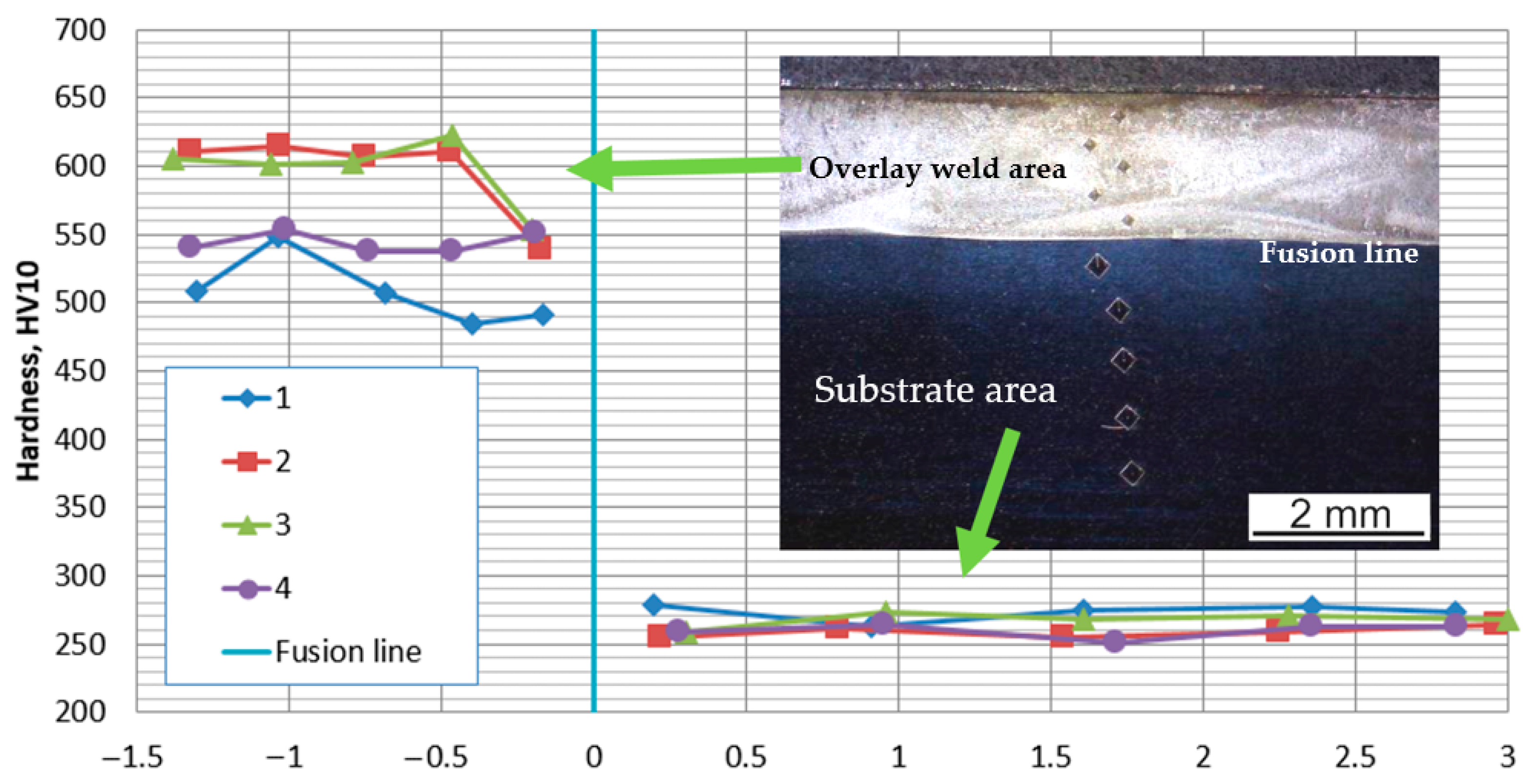
Hardness measurements were performed in the cross-section using the Vickers method with an indenter load of 10 kG (HV10). Measurements were made in the coating and in the substrate material below the coating (Figure 3a). The placement of measurements in every line is shown in Figure 10. Before starting overlay hardness measurements, substrate hardness was measured, obtaining the result of 261 ± 8 HV10. Table 3 presents the average values of hardness HV10 for four measurements lines (acc. to Figure 3a) for each overlay weld of the tested samples. Hardness indicates that in the substrate, both in the HAZ and in the base metal, there were no changes in hardness compared to the initial state, and the measurement obtained is similar for all overlays tested (261 HV10). The coating is characterized by a scatter of measurement results, where at the edges of the overlay, weld values of approximately 500–550 HV10 (lines 1 and 4) and, in the central part (lines 2 and 3), values of approximately 600 HV10 were noticed. Moreover, in the overlay at the fusion line, the hardness decreases to 550 HV10. An example of hardness HV10 distribution in each measurement line in sample 2 is shown in Figure 10.

4. Discussion

The technological tests of overlay welding and overlay tests have shown that it is possible to obtain coatings with small fusion using plasma arc cladding technology. Obtaining fusion below 0.1 mm ensures correct and good adhesion of the coating to the substrate and a narrow transition zone, where mixing of the substrate and the coating material occurs. The small mixing metal volume ensures the possibility of making single-layer coatings with low Fe content on the weld surface. Low Fe concentration on the surface has a positive effect on the corrosion resistance. Coatings with the use of low current parameters are characterized by a uniform shape and a smooth surface. The surface gently descends towards the edge and the substrate surface, which indicates good wetting of the metal surface with the liquid metal of the coating. The shape of the coating indicates that the coatings are applied one next to the other with an overlap of approximately 10%–15%, which will ensure an appropriate and uniform surface during cladding. At the same time, greater mixing of the substrate with the coating is observed at the edges, which means that there may be an increased iron content on the surface. Thus, the overlap of coatings in this area will ensure a reduction in the Fe concentration, where two layers of coating will occur. The area at the edges of the coating is characterized by a slightly lower hardness (approximately 550 HV10) than in the central part (approximately 600 HV10). This indicates that the abrasion of the coating will not occur evenly but will provide, especially at the edges, resistance to coating chipping and, therefore, a predictable service life. Chipping causes a sudden loss of the coating after an unspecified time, often below the planned service life, making them unacceptable coating defects. During chipping, large fragments can damage the device. The resistance to chipping (cracking) is also provided by the transition layer between the coating and the material, where the hardness also drops to approximately 550 HV10. The reduced (decreased) hardness in this area and the eutectic structure constitute a soft and plastic buffer layer between the substrate and the overlay weld. The eutectic structure also causes a natural inhibition of operational cracks, which, even if initiated on a hard coating, will stop on the transition layer. The longitudinal crack in the coating in one sample indicates that it is important during the overlay welding to maintain the heat input regimes to avoid the beginning of the crack and its further growth during cooling due to increasing stresses. Initial overlay welding tests carried out to find favorable parameters revealed that both longitudinal and transverse cracks will occur when the coating cools too quickly, which makes preheating essential for the correct course of the process, causing a decrease in the cooling rate. Due to the ferritic–austenitic substrate steel, technological tests should always be carried out to determine the preheating temperature. This is due to the need to avoid or limit the occurrence of carbide or σ phase precipitates in the HAZ under the overlay weld. The tests revealed the appearance of a small amount of fine σ phase precipitates, the amount of which does not cause significant changes in the properties of the HAZ. However, if its amount were to increase, it would form a continuous band, which is characterized by high hardness and brittleness and could lead to the detachment of the entire coating. The cooling conditions will depend on the dimensions of the welded element and the thickness of the material. On the substrate side, because of the small depth of fusion, only a slight grain growth of the grain occurred, indicating that the properties of the steel did not change. This is confirmed by both microscopic examinations and hardness measurements. Typically, dendrites consist of a Co-rich solid solution and eutectics composed of the Co-rich phase and M7C3/M 23C6 type carbides (M = Cr, Co, W). Such a structural structure promotes high hardness but also resistance to abrasion and chipping, which is particularly important in the case of overlay welding of mill elements or other rotating devices. This is indicated by the research of Hou et al. [34], who showed that the coarser eutectic structure of the overlay promotes greater resistance to abrasion than the precipitations of M23C6 carbides themselves. Carbide precipitations cause an increase in the hardness of the coating.

5. Conclusions

  • The examination of the sprayed layers indicates a favorable and uniform distribution of dispersive precipitates of the strengthening phase in the cross-section. The strengthening phase is formed by tungsten carbides and eutectics, and it should be assumed that the share of the eutectic structure is crucial for abrasion resistance.
  • The overlay weld is characterized by a lack of porosity and may contain single transverse and longitudinal cracks resulting from the structure and the occurrence of eutectics in the interdendritic areas. The key parameter is to ensure the appropriate cooling conditions, which should be determined experimentally.
  • At the substrate–coating boundary, there is a narrow (up to approximately 0.1 mm) transition layer free of precipitates, formed mainly by mixing the powder matrix and the substrate metal. The substrate surface has melted to a small extent, ensuring good adhesion of the coating in areas where the surface was wetted and a small share of iron in the coating. Therefore, it should be assumed that it is possible to produce single-layer coatings, which ensures their small thickness with limited iron content on the surface.
  • In the case of improper surface conditions, a brittle area of the overheated substrate with σ phase precipitates may form in the HAZ. The presence of the σ phase was observed in all 5 samples tested. The tested coatings did not reveal the presence of a continuous band of σ phase precipitates, ensuring a low risk of the coating detaching from the substrate.
  • The surfacing conditions ensured favorable hardness (approximately 600 HV10) of the coating, which ensures high abrasion (wear) resistance. However, the high hardness should be attributed exclusively to carbide precipitates. Favorable results were obtained without additional post-surfacing processing (aging), which could promote carbide growth.
  • It should be assumed that the smooth transition will help to avoid crack development in that region.
Future work: For a single-bead overlay weld, a detailed microstructure analysis using TEM to evaluate the carbide type and XRD analysis to evaluate γ/ε-Co proportion and wear resistant tests is needed. In technological tests, we plan to evaluate the condition from multibead cladding and allowed heat input conditions.

Funding

This study was funded by Polish Ministry of Science, grant number 16.16.110.663.

Institutional Review Board Statement

Not applicable.

Informed Consent Statement

Not applicable.

Data Availability Statement

Detailed results available upon request to the author.

Conflicts of Interest

The author declares no conflicts of interest.

References

  1. Zhang, H.; Mei, K.; Guo, W.; Li, Z.; Lai, Y.; Zhao, W.; Xiao, G.; Zhang, Y.; Cha, X. Comparative study on microstructures and properties of air-cooled and water-cooled Fe-based plasma arc cladding layers. J. Mater. Res. Technol. 2023, 23, 1599–1608. [Google Scholar] [CrossRef]
  2. Wang, L.; Chai, L.; Xu, S.; Liu, S.; Gan, S.; Chen, L.; He, X.; Polcar, T.; Daghbouj, N.; Li, B. Study on the corrosion behavior of laser surface remelted and laser cladding of ferritic/martensitic steels after exposure to lead-bismuth eutectic at 700 °C. J. Nucl. Mater. 2024, 590, 154888. [Google Scholar] [CrossRef]
  3. Xu, N.; Pang, C.; Tong, W.; Liu, J.; Li, L.; Xu, P. Evaluation of microstructure, mechanical properties and osseointegration capacity of laser cladding β-type TiNbZr coatings. Mater. Today Commun. 2024, 41, 110298. [Google Scholar] [CrossRef]
  4. Sigmund, M. Plasma overlay welding of cobalt alloy. MM Sci. J. 2019, 2019, 2982–2986. [Google Scholar] [CrossRef]
  5. Zhao, J.; Gao, Q.; Wang, H.; Shu, F.; Zhao, H.; He, W.; Yu, Z. Microstructure and mechanical properties of Co-based alloy coatings fabricated by laser cladding and plasma arc spray welding. J. Alloys Compd. 2019, 785, 846–854. [Google Scholar] [CrossRef]
  6. Chen, C.; Li, W.; Tu, F.; Qin, T. Effect of Heat Input on Tin Bronze-Induced Intergranular Cracks During Arc Cladding Process. Crystals 2024, 14, 926. [Google Scholar] [CrossRef]
  7. Momin, A.G.; Khatri, B.C.; Chaudhari, M.; VShah, U.; Valaki, J. Parameters for cladding using plasma transfer arc welding—A critical. Mater. Today Proc. 2023, 77, 614–618. [Google Scholar] [CrossRef]
  8. Sankarapandian, S.; Kumar, N.P.; Kannan, A.R.; Shanmugam, N.S. Microstructure, Mechanical Properties, and Corrosion Behavior of Co-Based Stellite 6 Multilayer Overlays Deposited on ASTM A36 Steel by Gas Metal Arc Welding Process. Steel Res. Int. 2023, 94, 2200889. [Google Scholar] [CrossRef]
  9. Xiong, J.; Nie, F.; Zhao, H.; Zheng, L.; Luo, J.; Yang, L.; Wen, Z. Microstructure evolution and failure behavior of stellite 6 coating on steel after long-time service. Coatings 2019, 9, 532. [Google Scholar] [CrossRef]
  10. Giudice, F.; Missori, S.; Scolaro, C.; Sili, A. A Review on Metallurgical Issues in the Production and Welding Processes of Clad Steels. Materials 2024, 17, 4420. [Google Scholar] [CrossRef] [PubMed]
  11. Kabakcı, F.; Acarer, M. Effect of cobalt on Microstructure and toughness properties of 9Cr-1.8W-0.4Ni-xCo weld metal. Int. J. Press. Vessel. Pip. 2024, 211, 105285. [Google Scholar] [CrossRef]
  12. Hu, K.; Tian, Y.; Jiang, X.; Yu, H.; Sun, D. Microstructure regulation and performance of titanium alloy coating with Ni interlayer on the surface of mild steel by laser cladding. Surf. Coat. Technol. 2024, 487, 130939. [Google Scholar] [CrossRef]
  13. Kannan, T.; Murugan, N. Effect of flux cored arc welding process parameters on duplex stainless steel clad quality. J. Mater. Process. Technol. 2006, 176, 230–239. [Google Scholar] [CrossRef]
  14. Rozmus-Górnikowska, M.; Cieniek Blicharski, M.; Kusiński, J. Microstructure and microsegregation of an inconel 625 weld overlay produced on steel pipes by the cold metal transfer technique. Arch. Metall. Mater. 2014, 59, 1081–1084. [Google Scholar] [CrossRef]
  15. Zhao, X.; Wang, Z.; Jin, J.; Huang, Y.; Yue, C.; Yang, L. Study on the in-situ generation of hard phases and microstructural and mechanical properties in Ni-WC/W2C cladding layers prepared by TIG arc. Int. J. Refract. Met. Hard Mater. 2025, 128, 106985. [Google Scholar] [CrossRef]
  16. Rykała, J.; Różański, M. Plasma Transferred Arc (PTA) Cladding and TOPTIG Cladding of Tubes Made of Steel 13CrMo4-5. Biul. Inst. Spaw. 2021, 6, 37–45. [Google Scholar] [CrossRef] [PubMed]
  17. Liu, F.; Liu, C.; Chen, S.; Tao, X.; Zhang, Y. Laser cladding Ni-Co duplex coating on copper substrate. Opt. Lasers Eng. 2010, 48, 792–799. [Google Scholar] [CrossRef]
  18. Ma, W.; Xu, X.; Xie, Y.; Bei, Z.; Yuan, Y.; Yu, H.; Sun, D. Microstructural evolution and anti-corrosion properties of laser cladded Ti based coating on Q235 steel. Surf. Coat. Technol. 2024, 477, 130383. [Google Scholar] [CrossRef]
  19. Li, D.; Zhang, C.; Wang, R.; Zhang, J.; Hu, R.; Zhang, Y.; Li, G.; Lu, X. Microstructure and properties evolution of Co06/Ni60A duplex coating on copper by plasma cladding. Surf. Coat. Technol. 2022, 429, 127978. [Google Scholar] [CrossRef]
  20. Huang, J.; Liu, S.; Yu, S.; An, L.; Yu, X.; Fan, D.; Yang, F. Cladding Inconel 625 on cast iron via bypass coupling micro-plasma arc welding. J. Manuf. Process. 2020, 56, 106–115. [Google Scholar] [CrossRef]
  21. Deng, X.; Zhang, G.; Wang, T.; Ren, S.; Bai, Z.; Cao, Q. Investigations on microstructure and wear resistance of Fe-Mo alloy coating fabricated by plasma transferred arc cladding. Surf. Coat. Technol. 2018, 350, 480–487. [Google Scholar] [CrossRef]
  22. Bozeman, S.C.; Isgor, O.B.; Tucker, J.D. Effects of processing conditions on the solidification and heat-affected zone of 309L stainless steel claddings on carbon steel using wire-directed energy deposition. Surf. Coat. Technol. 2022, 444, 128698. [Google Scholar] [CrossRef]
  23. da Cruz Junior, E.J.; Varasquim, F.M.F.A.; de Mendonça, V.R.; Ventrella, V.A.; Gonçalves, A.C.; Fagundes Junior, J.G.; Zambon, A.; Calliari, I. Impact of Heat Input on the Cladding of Super Austenitic Stainless Steel Through the Gas Tungsten Arc Welding Process on ASTM A516 Grade 70 Steel. Coatings 2024, 14, 1356. [Google Scholar] [CrossRef]
  24. Kim, H.; Jang, H.; Obulan Subramanian, G.; Kim, C.; Jang, C. Development of alumina-forming duplex stainless steels as accident-tolerant fuel cladding materials for light water reactors. J. Nucl. Mater. 2018, 507, 1–14. [Google Scholar] [CrossRef]
  25. Chen, K.J.; Lin, H.M. Effects of Niobium Carbide Additions on Ni-Based Superalloys: A Study on Microstructures and Cutting-Wear Characteristics through Plasma-Transferred-Arc-Assisted Deposition. Coatings 2024, 14, 167. [Google Scholar] [CrossRef]
  26. Farias, F.W.C.; Filho, J.d.C.P.; Júnior, D.A.d.S.; de Moura, R.N.; Rios, M.C.G. Microstructural characterization of Ni-based superalloy 625 clad welded on a 9% Ni steel pipe by plasma powder transferred arc. Surf. Coat. Technol. 2019, 374, 1024–1037. [Google Scholar] [CrossRef]
  27. Eswara Prasath, N.; Selvabharathi, R. Influence of Plasma Transfer Arc Cladding of NiCrBFe filler powder on microstructure and tensile properties of Titanium Grade 2 and Ti 6Al-4V alloy dissimilar joint prepared by laser beam welding. Opt. Laser Technol. 2020, 128, 106206. [Google Scholar] [CrossRef]
  28. Kishore, K.; Jaiswal, N.; Prabhakaran, A.; Arora, K.S. Through-thickness microstructure and wear resistance of plasma transferred arc Stellite 6 cladding: Effect of substrate. CIRP J. Manuf. Sci. Technol. 2023, 42, 24–35. [Google Scholar] [CrossRef]
  29. Bin, K.; Yao, P.; He, R.; Zhang, P.; Zhu, Q. Effect of ZrC particle on microstructure and corrosion behavior of CoCrNi medium-entropy alloy fabricated by powder plasma arc cladding. J. Alloys Compd. 2024, 1008, 176612. [Google Scholar] [CrossRef]
  30. Duan, B.; Han, F.; Lin, N.; Nouri, M.; Liu, Z.; Yu, Y.; Zeng, Q.; Li, D.; Wu, Y. Wear performance of CoCrFeMnNi and CoCrFeMnNi-SiC coatings on 0Cr18Ni9Ti stainless steel fabricated by plasma transfer arc cladding. Tribol. Int. 2024, 200, 110163. [Google Scholar] [CrossRef]
  31. Li, C.; Kong, F.; Feng, L.; Sun, H.; Han, X.; Luo, F. Research on Ni-WC Coating and a Carbide Solidification Simulation Mechanism of PTAW on the Descaling Roll Surface. Coatings 2024, 14, 1490. [Google Scholar] [CrossRef]
  32. Mei, K.; Zhang, H.; Gao, H.; Guo, N.; Zhao, W. Microstructure and properties of Fe-VC pulsed plasma arc cladding layers under different cooling conditions. Ceram. Int. 2023, 50, 6490–6498. [Google Scholar] [CrossRef]
  33. Adamiak, M.; Appiah AN, S.; Żelazny, R.; Batalha, G.F.; Czupryński, A. Experimental Comparison of Laser Cladding and Powder Plasma Transferred Arc Welding Methods for Depositing Wear-Resistant NiSiB + 60% WC Composite on a Structural-Steel Substrate. Materials 2023, 16, 3912. [Google Scholar] [CrossRef]
  34. Yoon, B.H.; Ahn, Y.S.; Lee, C.H. The Effect of Dilution on HAZ Liquation Cracking in PTAWNi-Base Superalloys Overlay Deposit. ISIJ Int. 2002, 42, 178–183. [Google Scholar] [CrossRef]
  35. DuPont, J. Solidification of an Alloy 625Weld Overlay. Metall. Mater. Trans. A 1996, 27, 3612–3620. [Google Scholar] [CrossRef]
  36. Örnek, C.; Mansoor, M.; Larsson, A.; Zhang, F.; Harlow, G.S.; Kroll, R.; Carlà, F.; Hussain, H.; Derin, B.; Kivisäkk, U.; et al. The Causation of Hydrogen Embrittlement of Duplex Stainless Steel: Phase Instability of the Austenite Phase and Ductile-to-Brittle Transition of the Ferrite Phase–Synergy between Experiments and Modelling. Corros. Sci. 2023, 217, 111140. [Google Scholar] [CrossRef]
  37. Dong, L.; Peng, Q.; Xue, H.; Han, E.-H.; Ke, W.; Wang, L. Correlation of Microstructure and Stress Corrosion Cracking Initiation Behaviour of the Fusion Boundary Region in a SA508 Cl. 3-Alloy 52M DissimilarWeld Joint in Primary PressurizedWater Reactor Environment. Corros. Sci. 2018, 132, 9–20. [Google Scholar] [CrossRef]
  38. Kiszka, A.; Górka, J.; Kiszka, P. Plasma Powder Surfacing of Toughened Steel S690Q Performed Using the NiBSi Powder with a Tungsten Carbide Addition. Biul. Inst. Spaw. 2018, 2018, 43–50. [Google Scholar] [CrossRef]
  39. Tuz, L. Determination of the causes of low service life of the air fan impeller made of high-strength steel. Eng. Fail. Anal. 2021, 127, 105502. [Google Scholar] [CrossRef]
  40. Pu, J.; Xie, P.; Long, W.; Wu, M.; Sheng, Y.; Sheng, J. Effect of Current on Corrosion Resistance of Duplex Stainless Steel Layer Obtained by Plasma Arc Cladding. Crystals 2022, 12, 341. [Google Scholar] [CrossRef]
  41. ISO 3452-1:2021; Non-Destructive Testing—Penetrant Testing. Part 1: General Principles. ISO: Geneva, Switzerland, 2021.
  42. Yoo, C.-S.; Söderlind, P.; Cynn, H. The phase diagram of cobalt at high pressure and temperature: The stability of -cobalt and new -cobalt. J. Phys. Condens. Matter 1998, 10, L311–L318. [Google Scholar] [CrossRef]
  43. Hou, Q.Y.; Gao, J.S.; Zhou, F. Microstructure and wear characteristics of cobalt-based alloy deposited by plasma transferred arc weld surfacing. Surf. Coat. Technol. 2005, 194, 238–243. [Google Scholar] [CrossRef]
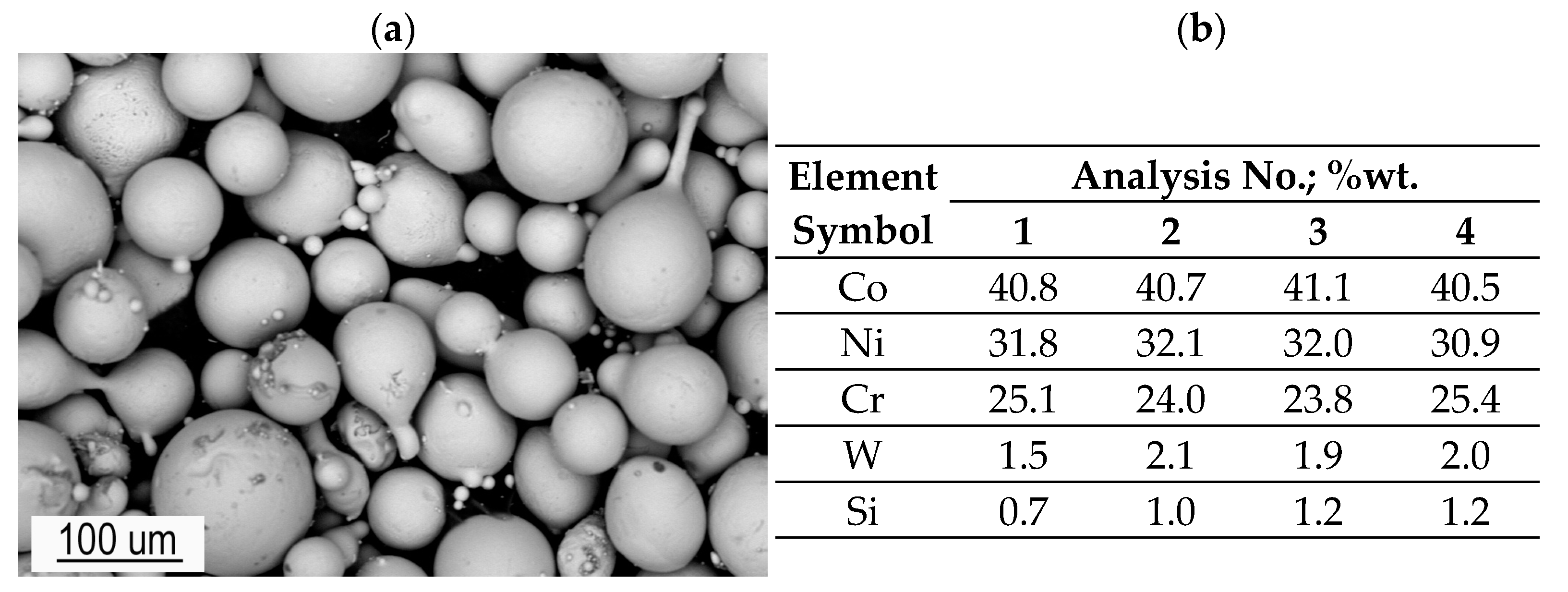
Figure 1. Powder Cobaltec 10092 morphology (a) and EDS analysis results (b).
Coatings 15 00069 g001
Figure 2. The surface morphology of the overlay weld (a) and after the PT test (b); the visible scale in mm.
Coatings 15 00069 g002
Figure 3. The macrostructure in the cross-section of the overlay weld by Castolin 10092 powder PTA with a longitude crack (a) and the sample without cracks (b); dot line—steel surface before overlay welding; green arrows—the placement of hardness measurements; white and yellow arrows—crack location in the unetched and etched sample.
Coatings 15 00069 g003
Figure 4. Ferritic–austenitic microstructure of substrate steel.
Coatings 15 00069 g004
Figure 5. The microstructure near the fusion zone: visible σ precipitation and the mixed zone, phase chemical composition by EDS (%wt.).
Coatings 15 00069 g005
Figure 6. The microstructure in the overlay weld area near the fusion line: visible single gas voids (arrows).
Coatings 15 00069 g006
Figure 7. The microstructure of the coating at the edge of the sample (a,b) and in the middle of the width (c,d); SEM images.
Coatings 15 00069 g007
Figure 8. The distribution of elements in the overlay weld (approx. 0.8 mm from the fusion line).
Coatings 15 00069 g008
Figure 9. The microstructure in the crack area. A visible crack at the boundary of the eutectic and dendrite cores.
Coatings 15 00069 g009
Figure 10. The hardness distribution in the cross-section of the substrate (right)–coating (left). Measured hardness in sample 2 acc. to sample numbering in Table 3 and line position in Figure 3a.
Coatings 15 00069 g010
Table 1. Chemical composition of substrate steel X2CrNiMoN22-5-3, %wt., Fe balance.
CCoCrNiSiPSCuMoNbTiNMnAl
0.0220.05822.84.60.280.030.0040.232.60.0070.0010.181.80.02
Table 2. Chemical composition of powder Cobaltec 10092, %wt.
BCCrFeNiSiWCo
1.711.4824.860.2133.001.004.22Bal.
Table 3. The results of hardness measurements in the substrate–coating cross-section along the measurement lines (acc. to Figure 3a). For the coating, the average of eight measurements separately in lines 2–3 and 1–4, and for the substrate, the average of twenty measurements.
Area Line No.Test Sample No.Average
12345
Substrate1 ÷ 4259 ± 3262 ± 5263 ± 2259 ± 3261 ± 4261 ± 4
Overlay weld2 and 3596 ± 14612 ± 11609 ± 16591 ± 20624 ± 9606 ± 12
1 and 4546 ± 29558 ± 19564 ± 27552 ± 24576 ± 29559 ± 23
Disclaimer/Publisher’s Note: The statements, opinions and data contained in all publications are solely those of the individual author(s) and contributor(s) and not of MDPI and/or the editor(s). MDPI and/or the editor(s) disclaim responsibility for any injury to people or property resulting from any ideas, methods, instructions or products referred to in the content.