Article

Effect of the Electrogalvanized and Galvannealed Zn Coatings on the Liquid Metal Embrittlement Susceptibility of High Si and Mn Advanced High-Strength Steel

1
State Key Laboratory of Advanced Special Steel, School of Materials Science and Engineering, Shanghai University, Shanghai 200444, China
2
State Key Laboratory of Development and Application Technology of Automotive Steels (Baosteel Group), Shanghai 201900, China
3
Automobile Steel Research Institute, R&D Center, Baoshan Iron & Steel Co., Ltd., Shanghai 201900, China
*
Authors to whom correspondence should be addressed.
Coatings 2025, 15(1), 28; https://doi.org/10.3390/coatings15010028
Submission received: 6 December 2024 / Revised: 23 December 2024 / Accepted: 27 December 2024 / Published: 1 January 2025
(This article belongs to the Special Issue Advances in Deposition and Characterization of Hard Coatings)

Abstract

:
The advanced high-strength steels (AHSSs) with high Si and Mn contents are extensively applied in the automobile manufacturing industry. To improve the corrosion resistance, Zn coatings are generally applied to the steel substrate. However, heat input and tensile stress occur during the resistance spot welding (RSW) process; thus, Zn-induced liquid metal embrittlement (LME) can be produced due to the existence of liquid Zn. Unfortunately, the LME occurrence can trigger the premature failure of welded joints, seriously affecting the service life of vehicle components. In this study, the LME behaviors in high Si and Mn RSW joints with electrogalvanized (EG) and galvannealed (GA) Zn coatings were comparatively investigated. Based on the Auto/Steel Partnership (A/SP) criterion, 16 groups of different welding currents were designed. In particular, four typical groups of RSW joints were selected to reveal the characteristics of the LME behaviors. Moreover, these four typical groups of EG and GA high Si and Mn RSW joints were, respectively, etched to measure their nugget sizes. The results indicated that with the increase in the welding current, more severe LME cracks tended form. As determined during the comprehensive evaluation of the 16 groups of EG and GA welded joints, higher LME susceptibility occurred in the EG high Si and Mn steels. It was concluded that the formation of Fe-Zn intermetallic compounds (IMCs) and internal oxide layers during the annealing process could account for the lower LME susceptibility in the GA welded joints.

1. Introduction

Compared to conventional high-strength steels, the automotive industry is increasingly focusing on the use of advanced high-strength steels (AHSSs), providing superior strength–ductility combinations and reduced weight [1,2]. These advantages include improved formability, enhanced energy efficiency, enhanced safety, etc. [3]. Typically, zinc coatings are applied to the surface of AHSS to enhance its corrosion resistance [4,5]. Zinc coatings can provide a sacrificial barrier that protects the underlying steel from environmental degradation, thereby extending the lifespan of the vehicle [6]. In addition to traditional hot-dip galvanizing (GI), electrogalvanizing (EG) and galvannealing (GA) processes are now widely utilized in actual manufacturing [7,8].
Both EG and GA techniques are extensively applied for body panels, structural components, etc. [9,10]. Electrogalvanizing involves immersing steel plates in an electrolyte solution containing zinc ions and applying an electric current [11]. Conversely, in the galvannealing process, steel sheets are first immersed in a zinc bath similar to the initial step in hot-dip galvanizing, and then subjected to a post-coating heat treatment. This heat treatment can promote the formation of Fe-Zn intermetallic compounds (IMCs) [12,13]. This IMC layer could provide a unique coating structure on the surface of steel substrate, providing superior adhesion and corrosion resistance [14].
Generally, a variety of welding techniques are widely employed in the automobile industry, including spot welding, narrow-gap welding, laser welding, etc. [15,16]. A typical vehicle body can contain between 3000 to 6000 weld spots [17]. Consequently, resistance spot welding (RSW) was favored for its convenience and low cost [18]. However, during RSW, liquid metal embrittlement (LME) occurs due to the presence of liquid zinc from the coating [19,20]. The molten zinc can penetrate along the grain boundaries of the steel substrate, triggered by the heat input and electrode pressure, leading to surface cracking [21]. The formation of LME can severely compromise the mechanical integrity and durability of steel plates, which brings detrimental effects in applications where high-quality welds are critical [22].
In recent years, considerable attention has been paid to the factors influencing the initiation and propagation of LME [23,24]. However, the underlying causes of LME formation remain uncertain. For example, despite the presence of identical microstructures in different steel substrates, the severity of LME can vary significantly [25]. Additionally, the element content was believed to affect the LME susceptibility of welded joints [26,27]. Hong et al. [28] demonstrated that in electrogalvanized twinning-induced plasticity (TWIP) steels containing 0–1.5 wt. % Si, the LME was exacerbated by the addition of Si. In our previous study, the results showed that compared to EG DP1180 steels, fewer and shorter LME cracks were observed in GI Zn-coated specimens protected by an internal oxide layer [29]. Consequently, the type of coating was considered a significant factor affecting the trend of LME formation [30,31].
The selection of galvanizing methods depends on specific industrial demands. It was found that EG and GA steels with an elevated Si content exhibited markedly different LME behaviors in our previous study [32]. To further improve the mechanical property, higher Mn content was added to the advanced high-strength steels [33]. When the Mn content increased, the steel strength was improved, but the LME susceptibility was significantly altered [34]. In light of the influential elements, it was necessary to evaluate the susceptibility of the welded joints containing high Si and Mn with either EG or GA coatings. Additionally, a more profound insight into the mechanism of the LME formation is essential to prolong the service life of the RSW joints.
The present study focused on the evaluation of LME in the EG and GA resistance spot welding joints with high Si and Mn contents. The LME cracks and the microstructure in the typical EG and GA specimens were examined using optical microscopy (OM). By analyzing and comparing the crack length and distribution, the LME susceptibility values in the high Si and Mn steel with EG and GA coatings were obtained, respectively. Furthermore, the mechanism responsible for the variety in the EG and GA specimens was comparatively analyzed and discussed.

2. Materials and Methods

The compositions of the high Si and Mn advanced high-strength steels with different galvanized processes (EG/GA) are listed in Table 1. The thickness of the GA specimens was 1.6 mm, whereas the thickness of the EG specimens was 1.2 mm for the purpose of galvanization and the requirements of their application.
The plates of high Si and Mn advanced high-strength steels were joined by a resistance spot welding technique. The domed electrodes used had a diameter of about 16 mm and featured a flat tip with a diameter of 6 mm. The entire welding procedure strictly complied with the standard of “LME cracking susceptibility test procedure for coated sheet steels”, which was formulated by the “Auto/Steel Partnership” (A/SP) [32]. Combined with the A/SP standard and the requirement for the practical production, 16 groups were designed, ranging from 7.0 kA to 14.5 kA, with a current interval of 0.5 kA. As illustrated in Figure 1a, the welding process started with a current of 5.0 kA and ended at 14.5 kA, utilizing a current profile consisting of 8 progressively sloped impulses. Each impulse lasted for 130 ms, followed by a cooling period of 40 ms. Additionally, the squeeze time was set to 1000 ms, and the holding time was 250 ms. Specifically, four groups of typical specimens were selected with the finished welding current at 8.0 kA, 10.0 kA, 12.0 kA, and 14.5 kA, respectively, to further analyze the LME characteristics.
The A/SP standard was widely applied to evaluate the LME severity in the EG and GA welded joints [35]. Based on the assessment method for LME, four types of cracks were defined, as shown in Figure 1b. Type A cracks are surface cracks found at the center of the weld spot. Type B cracks emerge outside the electrode indentation, while type C cracks are interfacial surface cracks between the two steel plates. Furthermore, type D cracks occur in the outer transition indentation.
The appearance of the spot-welded joints was characterized by an automated digital microscope (SmartZoom5, Zeiss, Oberkochen, Germany). The microstructure of the welded metal was revealed after being etched with a 4 vol.% nital solution, and the nugget sizes were measured. The LME cracks and the microstructure in the cross-section of the welded metals were observed via optical microscopy (OM, Axioscope5, Zeiss, Oberkochen, Germany). The length and distribution of LME cracks were counted and compared between the EG and GA specimens.

3. Results and Discussion

3.1. Tensile Property Test

Prior to performing resistance spot welding, four steel plates were subjected to tensile shear stress tests to confirm the stability. The stress–strain curves of the employed electrogalvanized and galvannealed steel plates are illustrated in Figure 2. Two of these specimens had EG coatings, while the other two were covered with GA coatings. As listed in Table 2, the EG specimens exhibited a yield strength exceeding 1000 MPa, a tensile strength over 1200 MPa, and an elongation at break of approximate 17%. The GA specimens demonstrated a yield strength of about 960 MPa, a similar tensile strength of around 1200 MPa, and an elongation at break also near 17%.

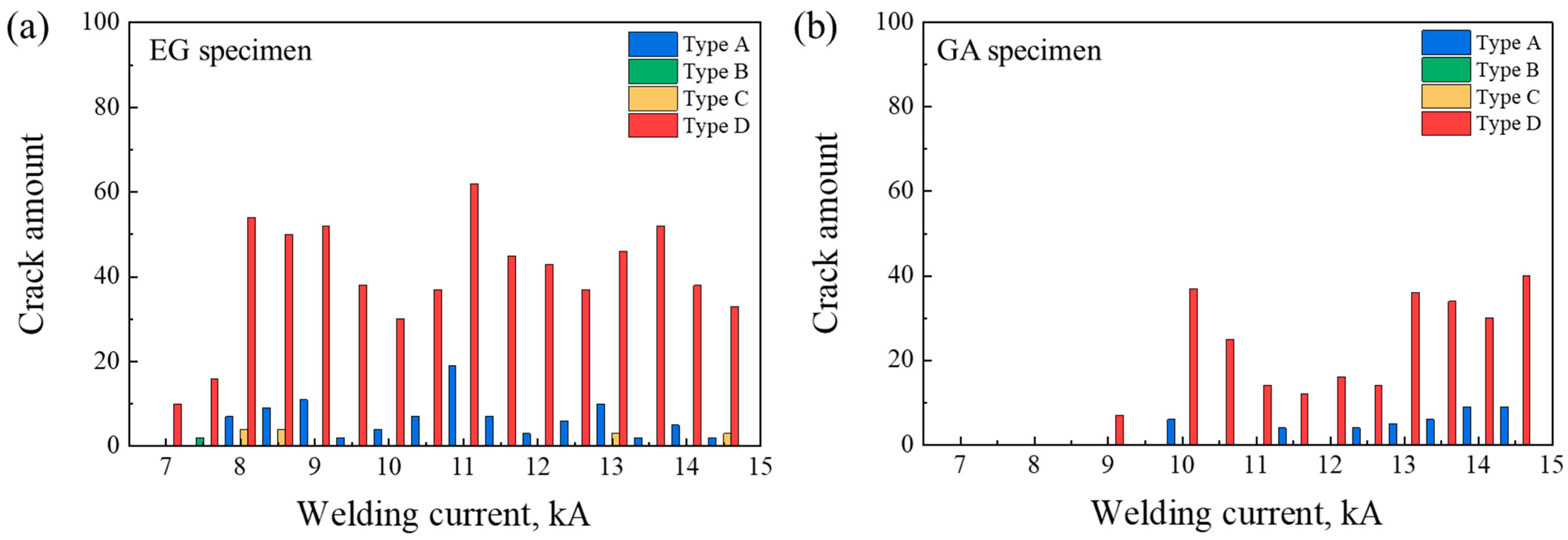
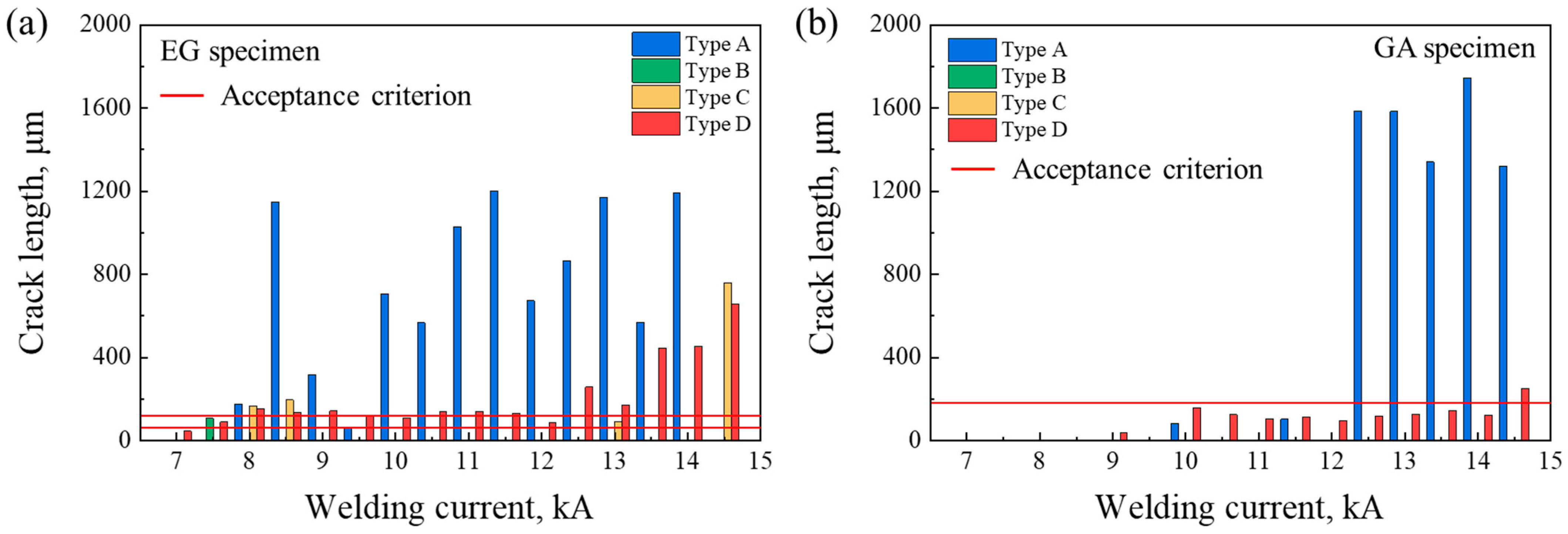
3.2. LME Observation of the RSW Joints at Various Welding Currents

To reveal the LME crack locations of the welded joints, the specimen surfaces were initially etched with (CH2)6N4-HCl solution to remove the zinc coating [36]. By controlling the etching time and etchant concentration appropriately, Zn penetration along the grain boundaries could be preserved. Figure 3 displays the surface morphology of the resistance spot welding joints after being etched. Figure 3a–d shows the EG specimens, while Figure 3e–h shows the GA specimens.
After pickling, the longest LME crack on the surface could be clearly seen. Based on the A/SP standard, both the grind and polish direction were perpendicular to the longest crack. Based on such steps, the LME cracks in the cross-section of the welded joints could be observed and analyzed. Figure 4 presents the metallographic images of the LME cracks in the cross-section of welded metal (WM) at 8.0 kA. The spot-welded specimens with electrogalvanic coating were ground and polished perpendicular to the longest type D crack. The nugget zone in the WM was clearly visible after being etched, with a length of 5279 μm. The longest type A crack detected was about 177 μm (see Figure 4b), which was within the acceptable limit at 8.0 kA. As for the type C cracks, the longest one was about 166 μm, significantly exceeding 5% of the thickness of the steel plate (1.2 mm). At the shoulder of the spot-welded indentation, several type D cracks could also be observed (see Figure 4d). The maximum length of the type D crack was also over the limitation of the evaluation standard, with a length of 155 μm, which was more than 10% of the steel plate’s thickness.
For the EG specimen welded at 10.0 kA, the diameter of nugget was about 5915 μm. As shown in Figure 5, both type A and D cracks were observable, whereas no significant type B or C cracks were detected. Notably, the longest type D crack was about 111 μm, less than 10% of the thickness of the steel plate. When the EG specimen was welded at 12.0 kA, the maximum lengths of the type A and D cracks were recorded as being 673 μm and 86 μm, respectively (see Figure 6). The longest type D crack was no more than 10% of the thickness of the steel plate. The nugget size had a length of 6151 μm.
Figure 7 illustrated the EG welded joint at a current of 14.5 kA, representing the typical condition of being above expulsion. The nugget size in the WM reached its maximum, measuring 6986 μm in length. The longest type A crack detected was about 283 μm. In comparison to specimens welded at currents below 14.5 kA, significantly longer type C cracks formed, with the maximum length reaching about 761 μm. Similarly, numerous type D cracks could be observed, among which the longest exceeded 10% of the steel plate’s thickness, measuring about 659 μm.
As the welding current increased, the nugget dimension of the RSW joints became larger. Higher heat input during welding can cause much more melting, leading to possible expulsion and deeper electrode indentation [37,38]. Patel et al. [39] investigated methods to relieve LME by optimizing suitable welding parameters. Figure 4, Figure 5, Figure 6 and Figure 7 demonstrate that a higher current and increased heat input could exacerbate the LME cracks. Consequently, the LME severity could be mitigated by controlling the appropriate welding current.
With regard to the spot-welded joints with GA coatings, the specimens at currents of 8.0 kA, 10.0 kA, 12.0 kA, and 14.5 kA were targeted. The length and distribution of cracks in the GA specimens were analyzed for each current level. As shown in Figure 8, the microstructure and the crack morphology of the joint welded at 8.0 kA were investigated. Figure 8a illustrates the martensite located at the WM, and the nugget size was about 5257 μm. No obvious LME crack can be observed in the cross-section of the GA specimen. Compared to Figure 4 and Figure 8, it is clearly that the EG joint exhibited a much more severe LME condition at a similar welding current. When the GA plates were welded at 10.0 kA, the length of the nugget increased to 7317 μm (see Figure 9a). An increased electrode force resulted in deeper indentation. The longest type A crack was detected, with a length of 85 μm (see Figure 9b). The longest type D crack was about 157 μm (see Figure 9c), which was still in the range of the 10% thickness of the steel plate (1.6 mm).
For the GA welded joint at a current of 12.0 kA, the diameter of the nugget was around 7003 μm. As shown in Figure 10, only type D cracks were observed, and the longest one was about 97 μm. The maximum length of the LME crack in the GA specimen at 12.0 kA was shorter than that in the EG one at the same current. With the increase in the welding current, a much larger nugget was formed, about 7420 μm in size (see Figure 11a). Compared to other currents, the joint at 14.5 kA exhibited the most severe LME cracks. Figure 11b,c indicate the morphology of the type A and D cracks. The longest type A crack went through almost the entire cross-section of the GA specimen. Additionally, the length of the type D crack was about 252 μm, which was far more than the 10% thickness of the GA steel plate. It was concluded that a greater welding current could aggravate the LME tendency due to the far greater heat input and induced larger tensile stress.

3.3. Difference in the LME Susceptibilities for the EG and GA High Si and Mn AHSS

To directly reflect the difference in LME susceptibility between the EG and GA specimens, the number of the 4 types of LME cracks were counted based on the 16 groups of different welding currents. As shown in Figure 12, the total number of LME cracks that appeared in the cross-section of the welded joints were measured and counted for each welding parameter. The LME crack number in the EG specimens was definitely much higher than that in the GA ones. Based on the criterion of the A/SP standard, the maximum length of LME cracks in both the EG and GA specimens in the 16 groups was observed and measured, respectively (see Figure 13). Four types of LME cracks occurred in the EG welded joints, while fewer and shorter type D cracks were detected in the GA ones. For the GA-coated specimen, only when the welding current increased to 14.5 kA did the maximum length of the type D crack reach over 10% of the thickness of the steel plate. However, no matter the kind of the LME cracks in the EG joints, all of them highly exceeded the A/SP standard. Therefore, proper selection of coating types and optimization of welding parameter are essential possible strategies to minimize the risk of LME and ensure the integrity of the welded joints.
Combined with the results regarding crack number and length, an upward trend of LME formation was present when the welding current was gradually increased, regardless of whether the welded joints had the EG or GA coating. That is to say, more severe LME cracks occurred in the joints as the welding current increased. The increase in welding current led to a greater heat input, which facilitated zinc melting and, consequently, enhanced the fluidity of the liquid zinc. Meanwhile, the increased electrode force applied larger tensile stress to the steel substrate, especially the grain boundaries. Therefore, there was a remarkable increase in the tendency for LME formation in the welded joints when increasing the welding current.
To shed more light on the factors that influence LME susceptibility, the Zn coatings of the EG and GA specimens were analyzed, respectively, as shown in Figure 14. Both the EG and GA specimens featured continuous Zn coatings with qualified adhesion to the underlying steel substrate. However, the coating thickness differed slightly, measuring about 8.2 μm for EG and 6.4 μm for GA specimens. A comparison between Figure 14b,d revealed a notable difference. An internal oxide layer was clearly observed in the GA specimen, while this feature was absent in the EG specimen. This protection layer could prevent the penetration of liquid Zn along the grain boundaries [29].
Overall, under the similar current condition, the LME severity in the spot-welded joints with EG coating was notably heavier than that in those with GA coating. During the galvannealing process, it was well known that several Fe-Zn intermetallic compounds (IMCs) could be formed via interdiffusion between the Fe in the substrate and Zn in the coating, driven by thermal energy. In the meantime, part of the Fe-Zn IMCs unexpectedly showed significant plasticity deformability [40,41]. Therefore, the corrosion resistance was improved by Fe-Zn alloying, which helped decrease the penetration of molten Zn along the grain boundaries [42,43,44]. Moreover, the alloy elements, like Si and Mn, could reduce the LME problems related to selective internal oxidation between the Zn coating and steel substrate [45]. In a word, the GA protective layer could effectively inhibit the initiation and propagation of LME cracks to some extent compared to the EG coating.

4. Conclusions

The effects of EG and GA Zn coatings on LME behavior in high Si and Mn steels were investigated in this study. The LME details of EG and GA high Si and Mn steels under various welding currents were observed. Furthermore, the maximum length and number of LME cracks were typically discussed. Moreover, the difference between the LME susceptibilities for the specimens with EG and GA Zn coatings was comprehensively analyzed. The main conclusions are drawn as follows:
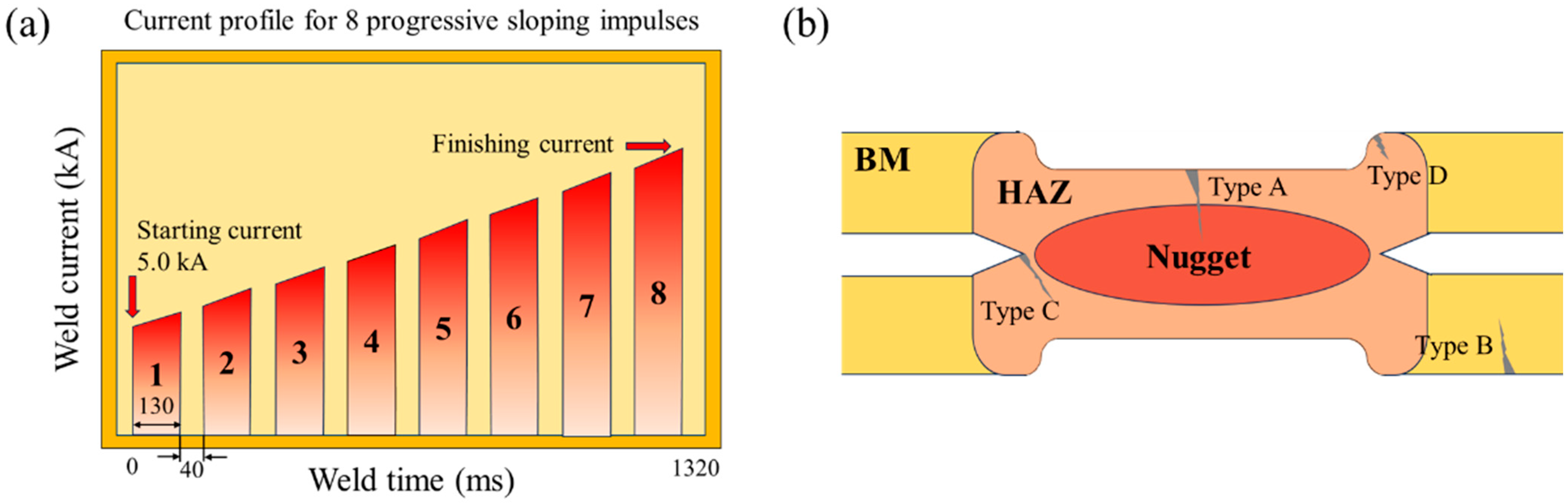
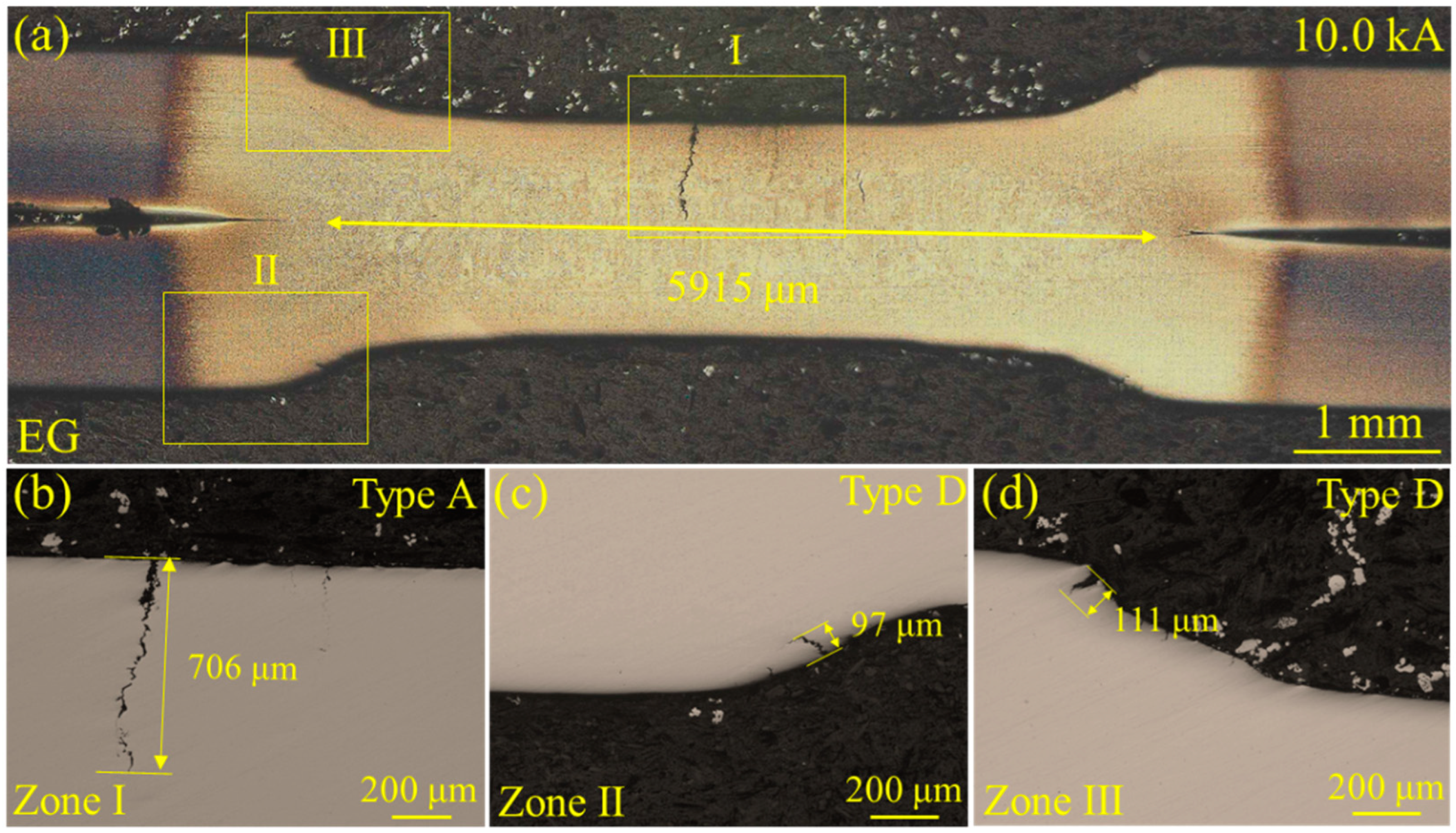
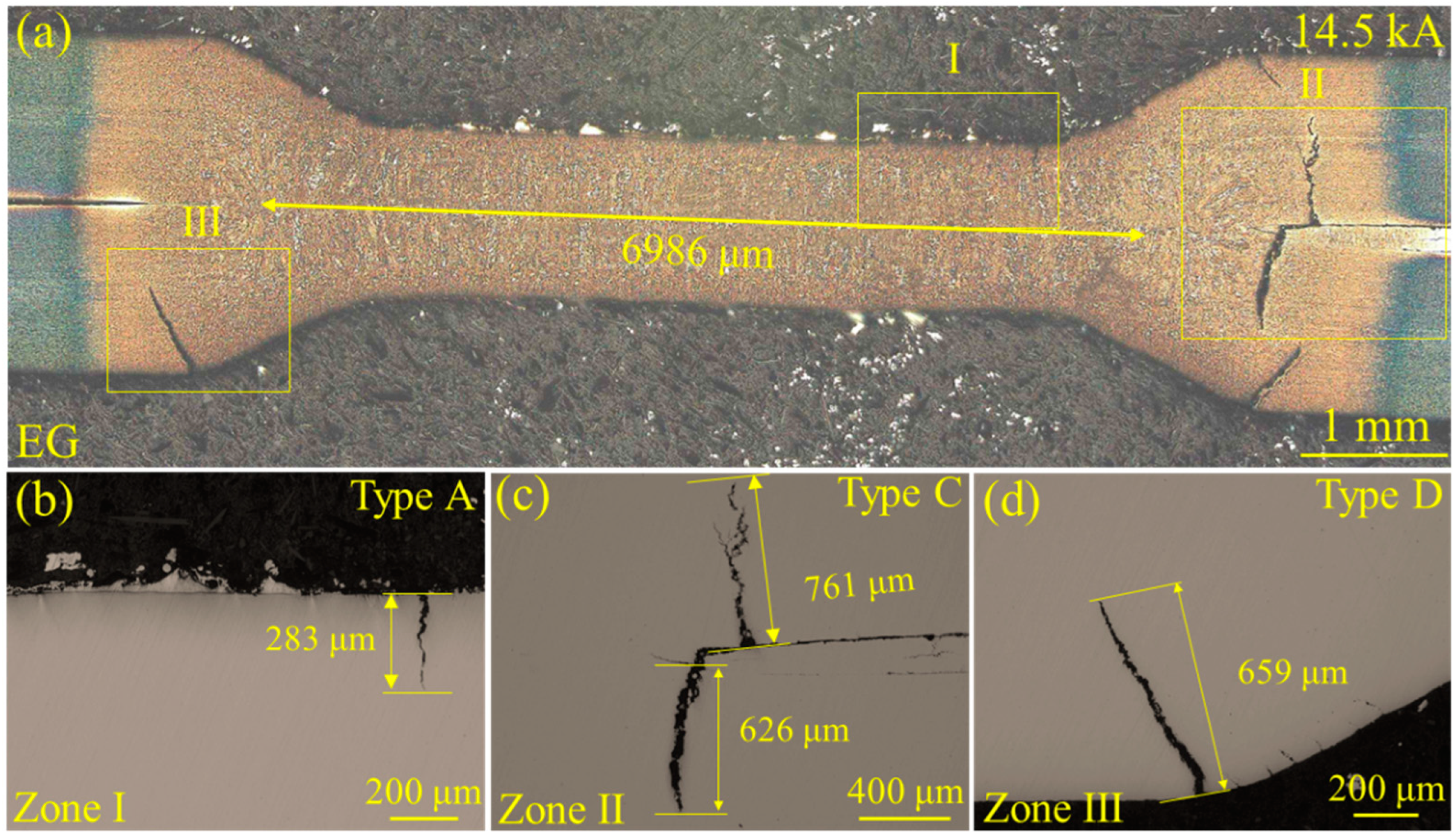
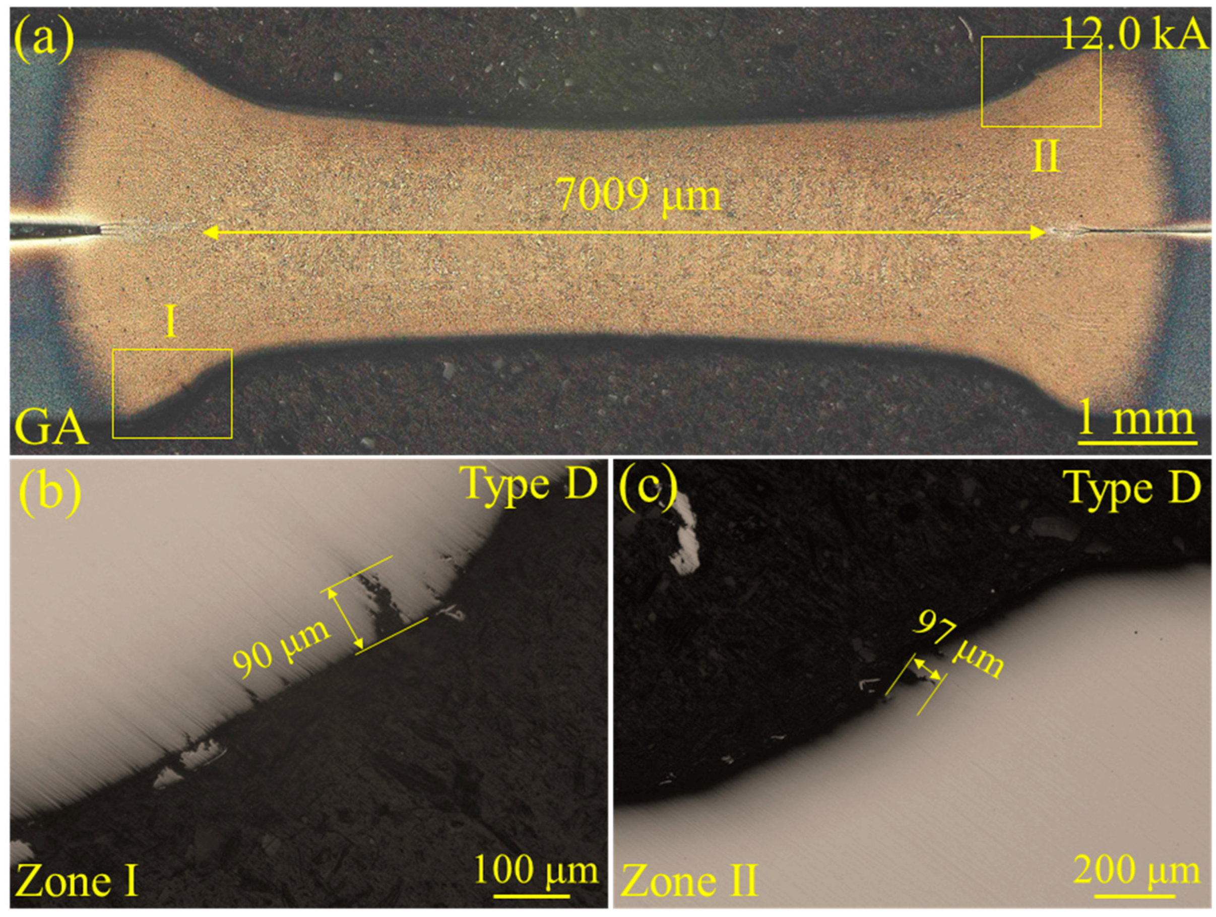
  • Both the yield strength and tensile strength of the EG specimens were similar to the GA specimens. Regardless of whether the high Si and Mn steels had an EG or GA coating, much more severe LME behaviors were observed as the welding current increased. For the EG specimens, four types of LME cracks were present, and the longest type D crack was 659 μm at 14.5 kA. For the GA specimens, only type A and D cracks were observed, and the longest type D crack was 252 μm at 14.5 kA.
  • For the high Si and Mn advanced high-strength steels with two kinds of coatings, both nugget sizes increased when raising the welding current. The enhanced heat input could produce much more melting, consequently leading to deeper electrode indentation. This indentation resulted in increased tensile stress, which in turn aggravated the formation of LME cracks in both electrogalvanized and galvanized high Si and Mn steels. The largest nugget sizes for the EG and GA specimen were 6986 μm and 7420 μm, respectively.
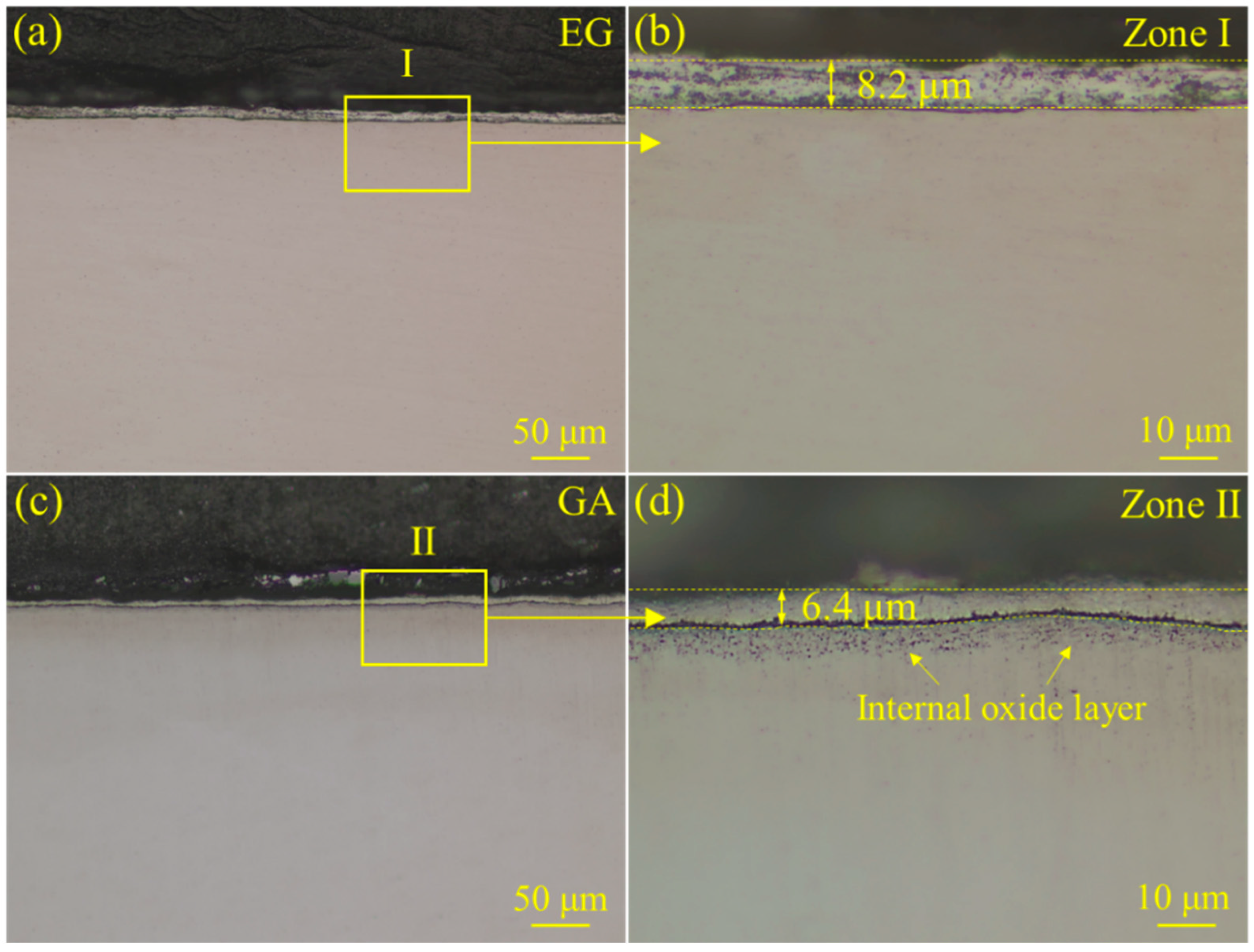
  • The EG specimens exhibited a relatively higher LME susceptibility compared to the GA ones. During the galvannealing process, Fe-Zn intermetallic compounds formed on the surface of the steel substrate. The existence of the protection layer could account for its lower susceptibility compared to the electrogalvanized steels, which lacked the Fe-Zn intermetallic compounds and internal oxide layers induced by the annealing process. Resistance spot welding did not yield satisfactory results for joining steels with high Si and Mn content, failing to produce qualified welded joints. Therefore, alternative welding techniques need to be explored.

Author Contributions

Writing—original draft, J.Z.; Writing—review and editing, Y.S., R.H. and Y.G.; Resources, M.L. and Y.G.; Formal analysis, J.Z., R.H. and Y.S.; Investigation, J.Z. and M.L.; Supervision, Y.G.; Validation, M.L. and Y.G. All authors have read and agreed to the published version of the manuscript.

Funding

This research received no external funding.

Institutional Review Board Statement

Not applicable.

Informed Consent Statement

Not applicable.

Data Availability Statement

No data were used for the research described in the article.

Conflicts of Interest

Author Ming Lei was employed by Baosteel Group and Baoshan Iron & Steel Co., Ltd. The remaining authors declare that the research was conducted in the absence of any commercial or financial relationships that could be construed as a potential conflict of interest.

References

  1. Phaoniam, R.; Lawanwong, K. Effect of weld-line position on springback behavior in advanced high-strength steel tailor-welded blanks on hat-shaped bending application. J. Adv. Join. Process. 2024, 10, 100241. [Google Scholar] [CrossRef]
  2. Rekha, M.Y.; Bikmukhametov, I.; Canulette, M.G.; Brewer, L.N.; Thompson, G.B. Hydrogen trapping by nanoscale Fe4C in MS1500 advanced high strength steel. J. Mater. Eng. Perform. 2023, 10, 100368. [Google Scholar] [CrossRef]
  3. Vijayan, V.; Changwook, J.; Park, Y.D. An investigation into the measurement and evaluation of volumetric voids in advanced high strength steel resistance spot welds. J. Mater. Eng. Perform. 2024, 24, 111665. [Google Scholar] [CrossRef]
  4. Taryba, M.; Cruz, A.; Macháčková, N.; Montemor, F.; Prošek, T.; Thierry, D. The effect of acidification on hydrogen uptake and corrosion resistance of advanced high-strength steels. J. Mater. Res. Technol. 2024, 33, 4149–4161. [Google Scholar] [CrossRef]
  5. Martin, A.; Texier-Mandoki, N.; Crusset, D.; Sabot, R.; Creus, J.; Refait, P. Corrosion behavior and sacrificial properties of Zn and Zn-Al coatings in conditions simulating deep geological disposal of radioactive waste at 80 °C. Coatings 2022, 8, 1044. [Google Scholar] [CrossRef]
  6. Hu, B.; Han, K.; Han, C.H.; Geng, L.S.; Li, M.; Hu, P.; Wang, X.P. Solid-solution-based metal coating enables highly reversible, dendrite-free aluminum anode. Coatings 2022, 12, 661. [Google Scholar] [CrossRef]
  7. Minenkov, A.; Mörtlbauer, T.; Arndt, M.; Hesser, G.; Angeli, G.; Groiss, H. Towards a dependable TEM characterization of hot-dip galvanized steels with low and high Si content. Mater. Des. 2023, 227, 111684. [Google Scholar] [CrossRef]
  8. Sahayata, B.; Mahanta, S.K.; Upadhyay, P.; Mendon, R.R.; Basu, A.; Das, S.; Mallik, A. An approach to improve corrosion resistance in electro-galvanized Zn-Al composite coating by induced passivity. Mater. Lett. 2023, 351, 135013. [Google Scholar] [CrossRef]
  9. Gogola, P.; Gabalcová, Z.; Kusý, M.; Ptačinová, J. High-temperature behaviour of Zn-based galvannealed coatings on steel. Materials 2023, 16, 3341. [Google Scholar] [CrossRef]
  10. Kim, S.J.; Park, J.S.; Jung, S.P. Corrosion-induced hydrogen evolution, absorption, and cracking behaviors of ultra-high-strength galvanized and galvannealed steel sheets. NPJ Mater. Degrad. 2022, 6, 31. [Google Scholar] [CrossRef]
  11. Shin, S.H.; Trang, T.T.T.; Chung, B.H.; Jeong, Y.G.; Lee, J.S.; Heo, Y.U. Microscopic study on the blister formation mechanism in electrogalvanized steel. Met. Mater. Int. 2024, 24, 12553. [Google Scholar] [CrossRef]
  12. Minenkov, A.; Arndt, M.; Knapp, J.; Hesser, G.; Gierl-Mayer, C.; Mörtlbauer, T.; Angeli, G.; Groiss, H. Interaction and evolution of phases at the coating/substrate interface in galvannealed 3rd Gen AHSS with high Si content. Mater. Des. 2024, 237, 112597. [Google Scholar] [CrossRef]
  13. Yu, J.S.; Liu, J.L.; Zhang, J.X.; Wu, J.S. Electron diffraction study on Fe-Zn gamma; intermetallic phase of a galvannealed IF steel sheet. Mater. Trans. 2005, 46, 1079–1082. [Google Scholar] [CrossRef]
  14. Kancharla, H.; Mandal, G.K.; Kumar, R.R.; Chakraborty, A.; Singh, S.S.; Mondal, K. Effect of annealing time on coating microstructure, frictional and electrochemical behavior of galvannealed interstitial-free steel. J. Mater. Eng. Perform. 2023, 32, 5932–5945. [Google Scholar] [CrossRef]
  15. Demiral, M.; Kadioglu, F. Analysis of fatigue performance of spot-welded steel T-profiles under cyclic torsional loading. Appl. Sci. 2024, 14, 10607. [Google Scholar] [CrossRef]
  16. Li, J.Z.; Yu, H.; Yin, X.; Kong, B.; Wen, K.; Sun, Q.; Wang, B.; Zeng, X.S. Welding characteristics of medium titanium plates with autogenous laser welding and narrow-gap laser filling welding modes. Materials 2024, 17, 4722. [Google Scholar] [CrossRef] [PubMed]
  17. Duran, E.T. Finite element based Multi-Axial low cycle fatigue analyses of Spot-Welded components and correlation with tests. Eng. Fail. Anal. 2022, 132, 105899. [Google Scholar] [CrossRef]
  18. Mezher, M.T.; Carou, D.; Pereira, A. Exploring resistance spot welding for grade 2 titanium alloy: Experimental investigation and artificial neural network modeling. Metals 2024, 14, 308. [Google Scholar] [CrossRef]
  19. Sun, Y.; Zhou, J.Y.; Hu, R.X.; Pan, H.; Ding, K.; Lei, M.; Gao, Y.L. The high-cycle tensile–shear fatigue properties and failure mechanism of resistance spot-welded advanced high-strength steel with a Zn coating. Materials 2024, 18, 4463. [Google Scholar] [CrossRef]
  20. Wang, X.N.; Xie, Y.; Liu, Z.G.; Sun, Q.; Shen, X.J.; Zhang, Q.Y.; Hu, Z.R.; Misra, R.D.K. Zn-induced liquid metal embrittlement and mechanical properties of advanced high-strength steel with resistance spot weld. Mater. Sci. Eng. A 2022, 843, 143088. [Google Scholar] [CrossRef]
  21. Kim, J.W.; Manladan, S.M.; Mahmud, K.; Jin, W.; Krishna, T.; Ji, C.; Nam, D.G.; Park, Y.D. Liquid metal embrittlement cracking in uncoated transformation-induced plasticity steel during consecutive resistance spot welding. Metals 2023, 13, 1826. [Google Scholar] [CrossRef]
  22. Ezequiel, M.; Proriol Serre, I.; Auger, T.; Héripré, E.; Hadjem-Hamouche, Z.; Perriere, L. The liquid metal embrittlement of a reactive system at room temperature: α-brasses in contact with the liquid eutectic Ga-In. Eng. Fail. Anal. 2024, 164, 108694. [Google Scholar] [CrossRef]
  23. Romedenne, M.; Hawkins, C.S.; Pierce, D.; Jun, J.; Dryepondt, S.; Pint, B.A. Evaluation of liquid metal embrittlement of F82H and 4340 steels in liquid lithium. Fusion Eng. Des. 2024, 206, 114601. [Google Scholar] [CrossRef]
  24. Wang, S.; Chen, C.B.; Ju, J.; Zhou, J.; Xue, F. Suppression of LME cracks in Sn bronze-steel system based on multi-material additive manufacturing. Mater. Lett. 2023, 335, 133775. [Google Scholar] [CrossRef]
  25. Yu, Y.; Zhang, Y.Q.; Cai, N.; Chen, W.X.; Wang, P.B.; Fu, C. Comparative investigation into the liquid metal embrittlement susceptibility during resistance spot welding of Zn–Al–Mg and GI coated advanced high strength steels. ISIJ Int. 2023, 63, 1233–1244. [Google Scholar] [CrossRef]
  26. Mei, H.J.; Cheng, L.Y.; Chen, L.; Yang, S.L.; Wang, F.F.; Li, J.F.; Kong, L.T. Effect of alloying elements on zinc-induced liquid metal embrittlement in steels: A first-principles study. Comput. Mater. Sci. 2024, 242, 113104. [Google Scholar] [CrossRef]
  27. Wallner, M.; Steineder, K.; Schneider, R.; Gruber, M.; Arndt, M.; Sommitsch, C. Unraveling the impact of the substitution of Si by Al on liquid metal embrittlement behavior of 3rd generation AHSS. Mater. Sci. Eng. A 2024, 899, 146446. [Google Scholar] [CrossRef]
  28. Hong, S.H.; Kang, J.H.; Kim, D.; Kim, S.J. Si effect on Zn-assisted liquid metal embrittlement in Zn-coated TWIP steels: Importance of Fe-Zn alloying reaction. Surf. Coat. Technol. 2020, 393, 125809. [Google Scholar] [CrossRef]
  29. Zhou, J.Y.; Sun, Y.; Hu, T.H.; Pan, H.; Lei, M.; Ding, K.; Gao, Y.L. Uncovering the mechanism of the LME susceptibility for the galvanized and electrogalvanized DP 1180 steels. Mater. Today Commun. 2024, 38, 108530. [Google Scholar] [CrossRef]
  30. Khan, M.S.; DiGiovanni, C.; Ghatei-Kalashami, A.; Shadab, S.G.; Song, G.; Goodwin, F.; Goodwin, F.; Zhou, Y.N. Effect of Zn-coating type on intergranular Cu-penetration in steels during weld-brazing. Mater. Lett. 2023, 344, 134442. [Google Scholar] [CrossRef]
  31. Bhat, R.S.; Balakrishna, M.K.; Parthasarathy, P.; Hegde, A.C. Structural properties of Zn-Fe alloy coatings and their corrosion resistance. Coatings 2023, 13, 772. [Google Scholar] [CrossRef]
  32. Gu, J.Y.; Zhou, J.Y.; Hu, R.X.; Sun, Y.; Lei, M.; Gao, Y.L. Comparative study on the liquid metal embrittlement susceptibility of the high-Si advanced high-strength steel with EG and GA Zn coatings. Metals 2024, 14, 1221. [Google Scholar] [CrossRef]
  33. Jiang, G.Y.; Wu, M.W.; Yang, X.G.; Wang, H.; Zhu, Y. Effect of Mn addition on microstructure and mechanical properties of GX40CrNiSi25-12 austenitic heat resistant steel. China Foundry 2024, 21, 205–212. [Google Scholar] [CrossRef]
  34. Dong, W.F.; Ding, K.; Pan, H.; Lei, M.; Wang, L.; Gao, Y.L. Role of Si content in the element segregation of galvanized QP980 advanced high strength steel. JOM 2022, 74, 2369–2376. [Google Scholar] [CrossRef]
  35. Dong, W.F.; Pan, H.; Sun, Y.; Zhou, J.Y.; Lei, M.; Ding, K.; Gao, Y.L. The sandwich-structured advanced high strength steel to resist the liquid metal embrittlement. J. Mater. Res. Technol. 2023, 25, 3167–3176. [Google Scholar] [CrossRef]
  36. Dong, W.F.; Pan, H.; Lei, M.; Wang, S.J.; Ding, K.; Gao, Y.L. Three-dimension characterization of the liquid metal embrittlement crack in the resistance spot welded joint of the advanced high strength steel. Mater. Today Commun. 2023, 34, 105322. [Google Scholar] [CrossRef]
  37. Song, S.; Shojaee, M.; Midawi, A.R.H.; Sherepenko, O.; Ghassemi-Armaki, H.; Biro, E. Influence of expulsion and heat extraction resulting from changes to electrode force on liquid metal embrittlement during resistance spot welding. J. Mater. Res. Technol. 2023, 23, 1458–1470. [Google Scholar] [CrossRef]
  38. Midawi, A.R.H.; Patel, M.; Shojaee, M.; Pearson, K.; Sherepenko, O.; Ghassemi-Armaki, H.; Biro, E. Effect of liquid metal embrittlement indent cracks on zinc coated 3rd generation AHSS mechanical performance. Metals 2023, 13, 491. [Google Scholar] [CrossRef]
  39. Patel, M.; Shojaee, M.; Sherepenko, O.; Midawi, A.R.H.; Ghassemi-Armaki, H.; Biro, E. Mitigating the influence of industrially relevant disturbances on LME severity of dissimilar resistance spot welded advanced high-strength steels. J. Mater. Res. Technol. 2023, 26, 22–31. [Google Scholar] [CrossRef]
  40. Park, H.; Jeong, Y.J.; Lee, K.; Goo, B.J.; Koh, H.J. Effect of galvannealing temperature on coating microstructure evolution correlated to flaking degradation on galvannealed interstitial-free steel. Surf. Coat. Technol. 2020, 404, 126446. [Google Scholar] [CrossRef]
  41. Wallner, M.; Steineder, K.; Schneider, R.; Commenda, C.; Sommitsch, C. Effect of galvannealing on the microstructural and mechanical properties of a Si and Al alloyed medium-Mn quenching and partitioning steels. Mater. Sci. Eng. A 2022, 841, 143067. [Google Scholar] [CrossRef]
  42. Bhattacharya, D.; Cho, L.; Colburn, J.; Smith, D.; Marshall, D.; van der Aa, E.; Pichler, A.; Ghassemi-Armaki, H.; Pottore, N.; Findley, K.O.; et al. Influence of selected alloying variations on liquid metal embrittlement susceptibility of quenched and partitioned steels. Mater. Des. 2022, 224, 111356. [Google Scholar] [CrossRef]
  43. Han, S.C.; Sanchez, D.F.; Grolimund, D.; Uhm, S.H.; Choi, D.Y.; Jeong, H.C.; Jun, T.S. Role of silicon on formation and growth of intermetallic phases during rapid Fe–Zn alloying reaction. Mater. Today Adv. 2023, 18, 100368. [Google Scholar] [CrossRef]
  44. Murugan, S.P.; Kim, J.; Kim, J.; Wan, Y.; Lee, C.Y.; Jeon, J.B.; Park, Y.D. Role of liquid Zn and α-Fe(Zn) on liquid metal embrittlement of medium Mn steel: An ex-situ microstructural analysis of galvannealed coating during high temperature tensile test. Surf. Coat. Technol. 2020, 398, 126069. [Google Scholar] [CrossRef]
  45. Dong, W.F.; Lei, M.; Pan, H.; Ding, K.; Gao, Y.L. Role of the internal oxidation layer in the liquid metal embrittlement during the resistance spot welding of the Zn-coated advanced high strength steel. J. Mater. Res. Technol. 2022, 21, 3313–3326. [Google Scholar] [CrossRef]
Figure 1. Schematic of the welding process and four types of liquid metal embrittlement (LME) cracks: (a) resistance spot welding (RSW) process; (b) type A, B, C, and D LME cracks possibly occurring in an RSW joint.
Coatings 15 00028 g001
Figure 2. The engineering stress–strain curves of the as-prepared electrogalvanized (EG) and galvannealed (GA) steel plates.
Coatings 15 00028 g002
Figure 3. Surface morphology of the RSW joints after pickling: (ad) the electrogalvanized (EG) welded joints at welding currents of 8.0 kA, 10.0 kA, 12.0 kA, and 14.5 kA, respectively, and (eh) the galvannealed (GA) welded joints at welding currents of 8.0 kA, 10.0 kA, 12.0 kA, and 14.5 kA, respectively.
Coatings 15 00028 g003
Figure 4. Metallographic images of the LME cracks in the cross-section of the EG specimen at a welding current of 8.0 kA: (a) the overall microstructure of the EG welded joint with the chemical etching, (b) microstructure of the type A crack in zone I, indicated by the yellow rectangle in (a), (c) microstructure of the type C crack in zone II, indicated by the yellow rectangle in (a), and (d) microstructure of the type D crack in zone III, indicated by the yellow rectangle in (a).
Coatings 15 00028 g004
Figure 5. Metallographic images of the LME cracks in the cross-section of the EG specimen at a welding current of 10.0 kA: (a) the overall microstructure of the EG welded joint with the chemical etching, (b) microstructure of the type A crack in zone, I indicated by the yellow rectangle in (a), (c) microstructure of the type D crack in zone II, indicated by the yellow rectangle in (a), and (d) microstructure of the type D crack in zone III, indicated by the yellow rectangle in (a).
Coatings 15 00028 g005
Figure 6. Metallographic images of the LME cracks in the cross-section of the EG specimen at a welding current of 12.0 kA: (a) the overall microstructure of the EG welded joint with the chemical etching, (b) microstructure of the type A crack in zone I, indicated by the yellow rectangle in (a), (c) microstructure of the type D crack in zone II, indicated by the yellow rectangle in (a), and (d) microstructure of the type D crack in zone III, indicated by the yellow rectangle in (a).
Coatings 15 00028 g006
Figure 7. Metallographic images of the LME cracks in the cross-section of the EG specimen at a welding current of 14.5 kA: (a) the overall microstructure of the EG welded joint with the chemical etching, (b) microstructure of the type A crack in zone I, indicated by the yellow rectangle in (a), (c) microstructure of the type C crack in zone II, indicated by the yellow rectangle in (a), and (d) microstructure of the type D crack in zone III, indicated by the yellow rectangle in (a).
Coatings 15 00028 g007
Figure 8. Metallographic images of the LME cracks in the cross-section of the GA specimen at a welding current of 8.0 kA: (a) the overall microstructure of the GA welded joint with chemical etching, (b) microstructure of zone I, indicated by the yellow rectangle in (a), and (c) microstructure of zone II, indicated by the yellow rectangle in (a).
Coatings 15 00028 g008
Figure 9. Metallographic images of the LME cracks in the cross-section of the GA specimen at a welding current of 10.0 kA: (a) the overall microstructure of the GA welded joint with the chemical etching, (b) microstructure of the type A crack in zone I, indicated by the yellow rectangle in (a), and (c) microstructure of the type D crack in zone II, indicated by the yellow rectangle in (a).
Coatings 15 00028 g009
Figure 10. Metallographic images of the LME cracks in the cross-section of the GA specimen at a welding current of 12.0 kA: (a) the overall microstructure of the GA welded joint with the chemical etching, (b) microstructure of the type D crack in zone I, indicated by the yellow rectangle in (a), and (c) microstructure of the type D crack in zone II, indicated by the yellow rectangle in (a).
Coatings 15 00028 g010
Figure 11. Metallographic images of the LME cracks in the cross-section of the GA specimen at a welding current of 14.5 kA: (a) the overall microstructure of the GA welded joint with the chemical etching, (b) microstructure of the type A crack in zone I, indicated by the yellow rectangle in (a), and (c) microstructure of the type D crack in zone II, indicated by the yellow rectangle in (a).
Coatings 15 00028 g011
Figure 12. Statistical results of the number of the 4 types of LME cracks for the 16 groups of different welding currents: the number of LME cracks in (a) the EG welded joints and (b) the GA welded joints.
Coatings 15 00028 g012
Figure 13. Statistical results of the maximum length of the 4 types of LME cracks for the 16 groups of different welding currents: the maximum length of the LME cracks in (a) the EG welded joints, and (b) the GA welded joints.
Coatings 15 00028 g013
Figure 14. Metallographic images of the Zn coatings on the EG and GA steel substrates: (a) EG steel, (b) microstructure of EG coating in zone I, indicated by the yellow rectangle in (a), (c) GA steel, and (d) microstructure of GA coating in zone II, indicated by the yellow rectangle in (c).
Coatings 15 00028 g014
Table 1. Chemical composition of the as-prepared high Si and Mn advanced high-strength steels (wt. %).
ElementsCMnSiPS
Specimens>0.18>2.6>1.6<0.03<0.01
Table 2. Mechanical properties of the as-prepared EG and GA steel plates.
SpecimenRp0.2/MPaRm/MPaAt/%
GA-1967120017
GA-2954119616.7
EG-11071126116.5
EG-21037123617
Disclaimer/Publisher’s Note: The statements, opinions and data contained in all publications are solely those of the individual author(s) and contributor(s) and not of MDPI and/or the editor(s). MDPI and/or the editor(s) disclaim responsibility for any injury to people or property resulting from any ideas, methods, instructions or products referred to in the content.

