Article

An Investigation of Carbon-Fiber-Reinforced Plastic Ablation by Femtosecond Laser Pulses for Further Material Cutting

by
Paulius Šlevas
1,*,
Justinas Minkevičius
1,
Orestas Ulčinas
1,
Sergej Orlov
1,
Egidijus Vanagas
1,*,
Anna Bilousova
2,
Denys Baklan
2 and
Oleksiy Myronyuk
2
1
Coherent Optics Laboratory, Department of Fundamental Research, Center for Physical Sciences and Technology, Sauletekio Ave. 3, LT-10257 Vilnius, Lithuania
2
Department of Chemical Technology of Composite Materials, Chemical Technology Faculty, Igor Sikorsky Kyiv Polytechnic Institute, Beresteiskyi Ave. 37, 03056 Kyiv, Ukraine
*
Authors to whom correspondence should be addressed.
Coatings 2025, 15(1), 104; https://doi.org/10.3390/coatings15010104
Submission received: 24 November 2024 / Revised: 15 January 2025 / Accepted: 16 January 2025 / Published: 18 January 2025
(This article belongs to the Special Issue Laser Surface Engineering and Additive Manufacturing)

Abstract

:
Carbon-fiber-reinforced plastic (CFRP) is a popular material possessing great properties, such as strength, lightness, and resistance to corrosion and the environment. Important steps in the production of various parts made of CFRP are surface structuring, milling, drilling and cutting processes. Here, we propose to use ultrashort pulse lasers to achieve the high-quality, low-heat-affected-zone ablation of CFRP. We investigated the ablation efficiency dependence on the processing parameters, such as the pulse duration, pulse energy and pulse overlap. We showed that good-quality results could be achieved using just low-/mid-average-power femtosecond laser equipment. We also discuss further cutting process optimization possibilities using ultrashort pulse lasers and show the possibility of HAZ-free CFRP cutting by femtosecond laser ablation.

1. Introduction

Today, carbon-fiber-reinforced plastic (CFRP) is used in various fields [1] due to its outstanding properties: lightness, strength, ease of formation, resistance to corrosion and the aggressive environment, etc. Due to these qualities, CFRP is used in various industries [2,3]: aerospace, automotive, marine, military, etc. However, some of the properties of this composite also cause additional problems that are more difficult to solve compared with the cases where conventional materials (metal, plastic, glass, etc.) are used. These difficulties are caused by the hardness of the carbon fiber itself [2] and the anisotropy of this composite material [4], where a portion of the volume is filled with plastic having significantly “weaker” mechanical and thermal properties [5,6]. This inhomogeneous and anisotropic volume of CFRP is difficult to process with traditional mechanical methods [7,8,9], where the desired processing quality is not achieved and additional operations are required to improve the quality.
Although laser non-contact material processing is widely used for many materials, CFRP processing adopting this method presents new issues due to the heat-affected zone (HAZ) [2,10]. The problems are caused by the inhomogeneity and anisotropy of the CFRP material, which differ strongly in the mechanical and thermal properties of the material. One of the currently applied methods of CFRP laser processing is based on the use of CW or pulsed kW power range nanosecond laser processing equipment [11,12,13]. This equipment is bulky, energy intensive and creates a significant HAZ at the cut site.
Material processing using a femtosecond light pulse laser is called “cold” laser processing [14,15]. The advantages of this approach are the minimization of the HAZ and the high processing accuracy [16,17,18,19,20]. An additional advantage of the femtosecond laser machining process is that by selecting the process parameters, similar ablation rates can be achieved for both the composite materials, namely, synthetic resin and carbon fiber, constituting the CFRP.
In this study, we showed the dependencies of CFRP femtosecond ablation efficiency on the process parameters: pulse duration, pulse energy and processing pitch distance. We demonstrated the ablation-optimization possibilities using just low-/mid-average-power femtosecond laser equipment instead of bulky kW power range CW or nanosecond lasers. This study was based on an investigation of the interaction of a focused femtosecond-duration light pulse with CFRP material. We demonstrated the methodology for finding CFRP ablation conditions that assured “cold” laser processing, and we also used these conditions to cut the CFRP.
Femtosecond laser processing is an attractive way to treat a wide range of materials, ranging from soft plastics to hard diamond-type materials [21,22,23,24,25]. The duration of the semi-second laser pulse allows us to treat the material with a very short and high-intensity light pulse. During the pulse, a certain volume of the material is excited, where a Coulomb explosion is induced [26,27] and further ablation of the excited material is removed, together with almost all of the energy of the light pulse supplied at the site. A femtosecond-scale light–matter interaction gives us minimal energy penetration further into the surrounding depth of the material. This happens because the electron–phonon relaxation time [28,29] is significantly greater than the femtosecond pulse duration and is generally above 1 picosecond in most materials [30,31,32,33]. This is why femtosecond scale laser processing is called “cold processing” and the HAZ can be minimized.
In CFRP, which is a composite material made from carbon-fiber-reinforced plastic, the electron–phonon relaxation process is quite complex for the evaluation of the thermal conductivity, as well as the electronic properties. For highly ordered carbon materials, such as graphene, the relaxation times are often in the subpicosecond range [34], while in more disordered structures, such as CFRP, the relaxation time might extend to a few picoseconds [35]. Specifically, the object of CFRP that is investigated here by means of the light–matter interaction responding rate is described in ref. [35], where the electron–phonon relaxation time value was obtained in the range of 2–6 picoseconds.

2. Experimental Results and Discussion

2.1. Optical Setup

For the CFRP fabrication, we used the optical setup depicted in Figure 1. A laser source that emitted around 4.1 mm ( 1 / e 2 ) diameter Gaussian beam at the wavelength of 1030 nm was used. The maximum power of the laser was 6 W and could be operated at a frequency of up to 200 kHz. The power was controlled by an external attenuator that consists of a half-wave plate (HWP) and a polarizer (Pol). The beam passed through a quarter-waveplate (QWP) to change its polarization to circular and was then focused to around 7.7 μm (at the 1 / e 2 intensity level) diameter by a microscope objective (10X Mitutoyo Plan Apo NIR, Kawasaki, Japan) that was mounted on a z stage. The Rayleigh length of the focused beam was around 37.5 μm. The commercially available 0.5 mm thick CFRP sample was placed on linear XY stages (Aerotech ant130-xy, Pittsburgh, PA, USA). We measured the initial surface roughness of the sample to be 0.78 μm. The surface profile and optical microscope picture are provided in Figure 1b,c, respectively. The CFRP was processed by hatching back and forth to ablate 0.5 mm × 0.5 mm squares. The distance between the hatch lines was 2.5 μm and the pulse-to-pulse overlap in a line was changed in our experiments. We also varied the single-pulse energy from 0.5 μJ to 16 μJ and the pulse duration from 0.19 ps to 8 ps . After the laser processing, the samples were washed in distilled water inside an ultrasonic bath, and the volume of ablated squares was measured using an optical profiler (Sensofar S neox, Barcelona, Spain).

2.2. Variation in Pulse-to-Pulse Distance

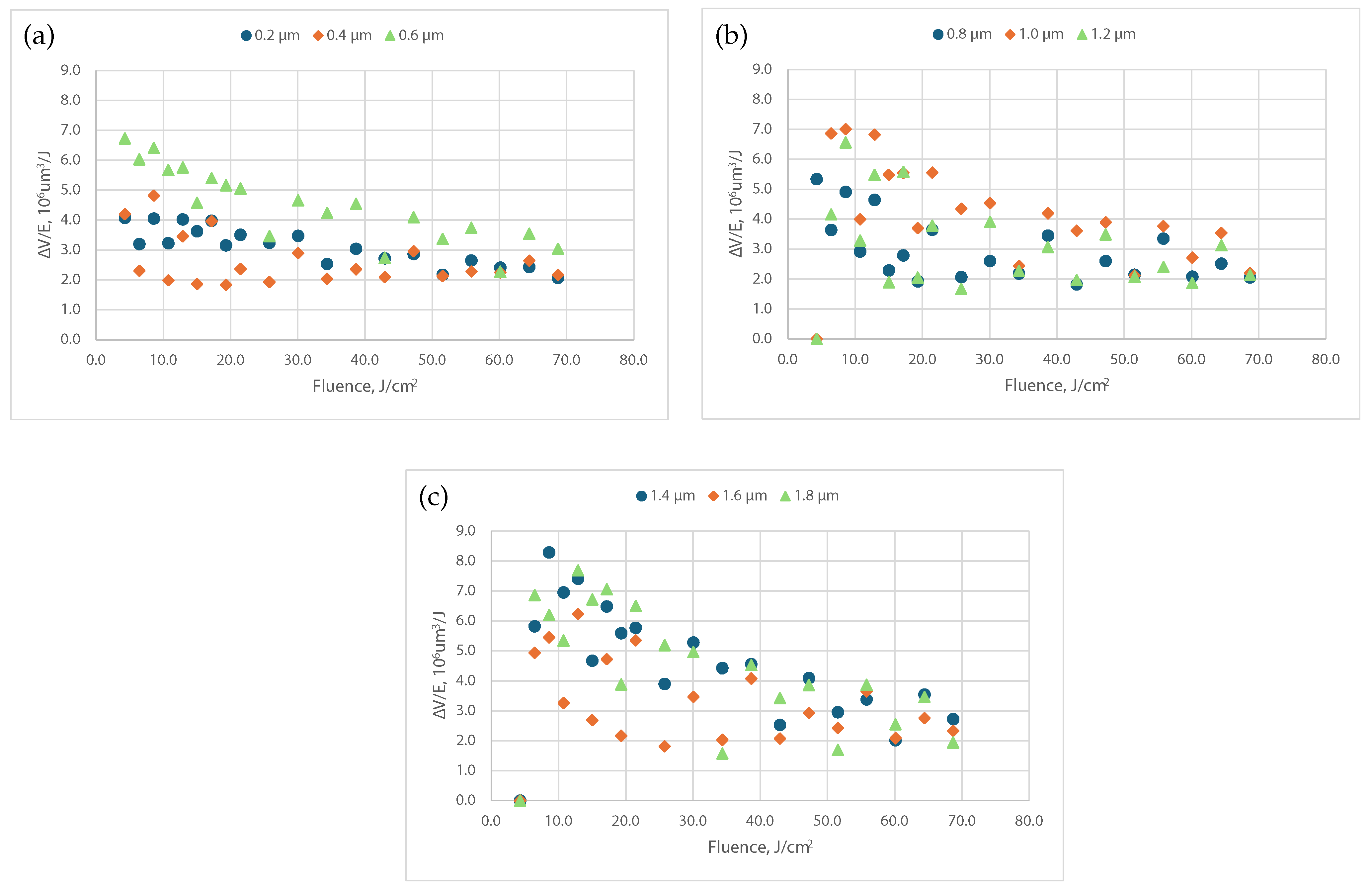
We started our work by considering the case where the pulse-to-pulse distance p changed within a hatch line. For this, we used the shortest available pulse duration of 0.19 ps . The distance between pulses was changed using the synchronized stage position and the laser trigger signal, while the stage speed was set to 10 mm / s . After the squares were processed and cleaned, the volume of the produced cavity was measured and divided by the total input energy to plot the energy specific volumes. The results are depicted in Figure 2. They are divided into three plots so that the data is easier to understand. In Figure 2a, it can be seen that increasing the pulse-to-pulse distance from 0.2 μm to 0.6 μm resulted in an overall increase in the energy specific volume. The highest value of 6.7 × 10 6  μm3/J was achieved using a 4.29 J / cm 2 fluence. In Figure 2b, the pulse-to-pulse distance was increased further to 1.2 μm. In this plot, the best energy specific volume of 7.01 × 10 6  μm3/J was achieved using an 8.59 J / cm 2 fluence and a 1 μm pitch between the laser pulses. For the cases of p = 0.8  μm and p = 1.2  μm, the ablation efficiencies were lower than for p = 1  μm. In this experiment, the best energy specific volume was achieved when the pulse-to-pulse distance was set to 1.4 μm and the fluence was set to 8.59 J / cm 2 (see Figure 2c). This pulse-to-pulse distance corresponded to a pulse overlap of 82% ( 100 % × ( 1 1.4 / 7.7 ) ). This was the optimal distribution of pulses on the sample surface to achieve the maximum ablation efficiency for the material. In addition, we could evaluate the minimum suitable and most efficient pulse fluence from the graph in Figure 2c. The most efficient ablation rate was not at the highest laser pulse energy, but at the lower laser pulse energy level. Using these conditions, it was possible to avoid excess laser energy supply to material surface, as well as further energy transfer to the bulk. One can also notice that the points in the graphs do not make smooth curves. This can be related to inhomogeneities in the sample. Carbon fiber is woven and filled with plastic, which does not guarantee a consistent carbon fiber density at every point of the sample.
We further looked at the surface roughness (Sa) values of the bottom of the ablated squares. For each pulse-to-pulse distance, we compared the Sa at the fluence level where the energy specific volume was the highest. The profiles are presented in Figure 3. The lowest Sa of 0.51 μm was achieved when the pulse-to-pulse distance was set to 0.2 μm (Figure 3). However, the energy specific volumes that used this parameter were among the lowest. The highest Sa of 1.42 μm was measured after ablating the cavity with p = 0.8 μm (see Figure 3d). The fiber structure was the most prominent in this case compared with the other profiles. For the most efficient case of p = 1.4 μm, the surface roughness was around 1 μm. That is, the roughness was sufficient for the most efficient energy specific volume ablation investigation. Further research of CFRP fast-processing-options discovery could be based on our present experimental data.

2.3. Variation in the Pulse Duration

Here, we selected a single pulse-to-pulse distance of 1.4 μm and compared the energy specific volumes and surface roughnesses for the case where the cavities were ablated using different pulse durations τ . The results are presented in Figure 4, where in (a), it can be seen that 190 fs performed the best in the range tested. Lower energy specific volumes were achieved at 500 fs and 1 ps , and the maximum values were reached at 6.4 J / cm 2 . The ablation efficiency dropped more for longer pulse durations, and a higher fluence was needed to reach the peak of the energy specific volume. The most efficient ablation was reached at 10.7 J / cm 2 and 12.9 J / cm 2 for 4 ps and 8 ps , respectively.
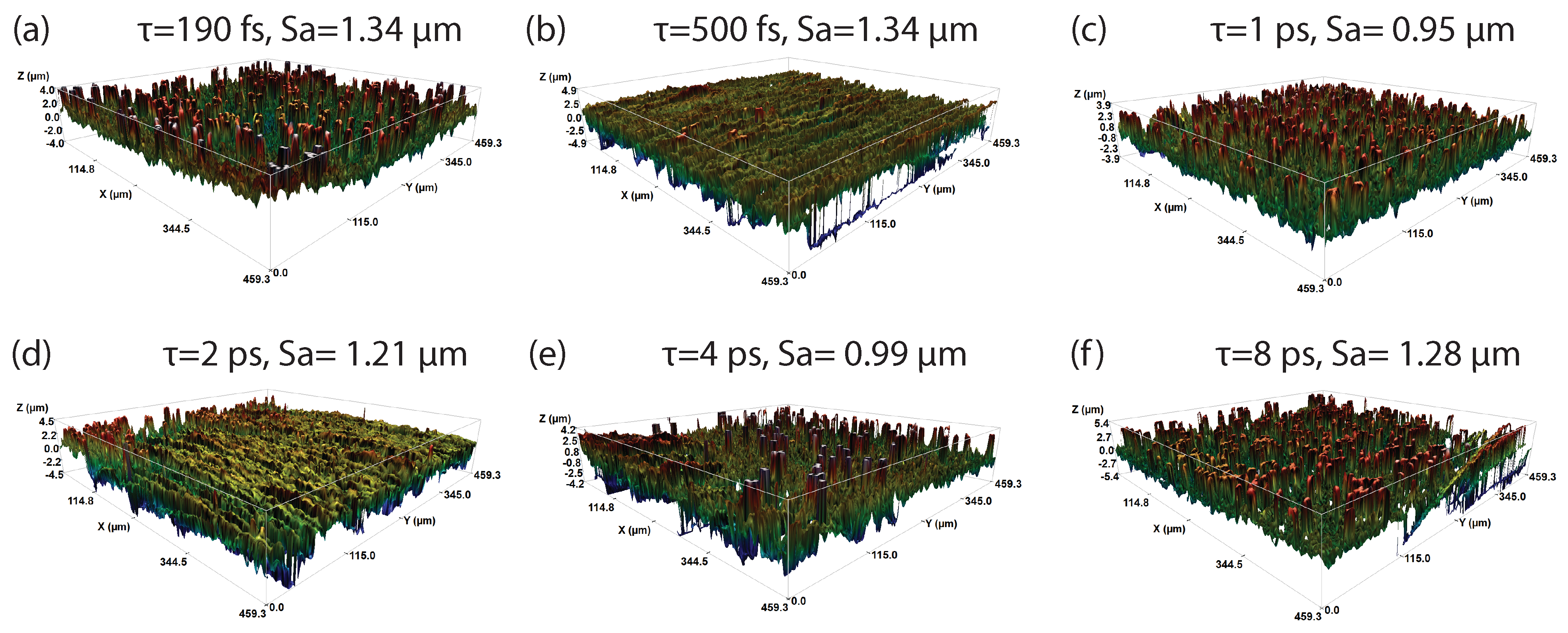
Furthermore, the point with the highest energy specific volume was selected from each pulse duration plot to capture the surface profiles and measure the Sa values that are presented in Figure 5. For the cases of 190 fs , 1 ps and 4 ps , the Sa was around 1 μm. A slightly higher Sa of around 1.3 μm was found after the ablation with 500 fs , 2 ps and 8 ps . Overall, there was little difference in the surface quality for the data points compared. According to the results of the influence of pulse duration on CFRP ablation, we saw a clear advantage of the shortest pulses. These results confirm the “cold” laser processing case, where the femtosecond-scale pulse duration held the advantage for processing very different materials. The similarities between the smooth ablations of both CFRP compounds (plastic and carbon fiber) at once, obtained at the most efficient fluence range, proved this effect in general. We demonstrated the feasibility of building a set of parameters for reliable, high-speed CFRP processing with low-/mid-power range femtosecond lasers.

2.4. Cutting CFRP

Lastly, to verify our predictions for the possibility to increase the processing speed, we changed the beam delivery system in the optical setup. We kept the same pulse duration, fluence and proportional pulse-to-pulse step range as in the best parameters obtained in the above experiments. Instead of focusing through a microscope objective, we used a scan head with an f-theta lens ( f = 100   mm ). The diameter of the beam spot on the sample surface using this setup was around 24 μm. We set the laser frequency to 200 kHz , the power to 3.9 W , a 7.8 μm line-to-line distance, and the scan speed to 858 mm / s . The fluence in this case was around 8.6 J / cm 2 , and the pulse-to-pulse distance was 4.3 μm, which corresponded to a pulse-to-pulse overlap of 82% ( 100 % × ( 1 4.3 / 24 ) ), at which the best ablation efficiency was found in Section 2.2. After ablating a 0.5 × 0.5 mm square, we measured the depth to be around 8.6 μm. This resulted in an energy specific volume of 14.8 μm3/J, which was higher compared with the best value shown in Figure 2. A higher scan speed led to increased heat accumulation and this, in turn, led to a greater ablation volume. Also, the focusing depth was around 10 times longer using the above-mentioned f-theta lens.
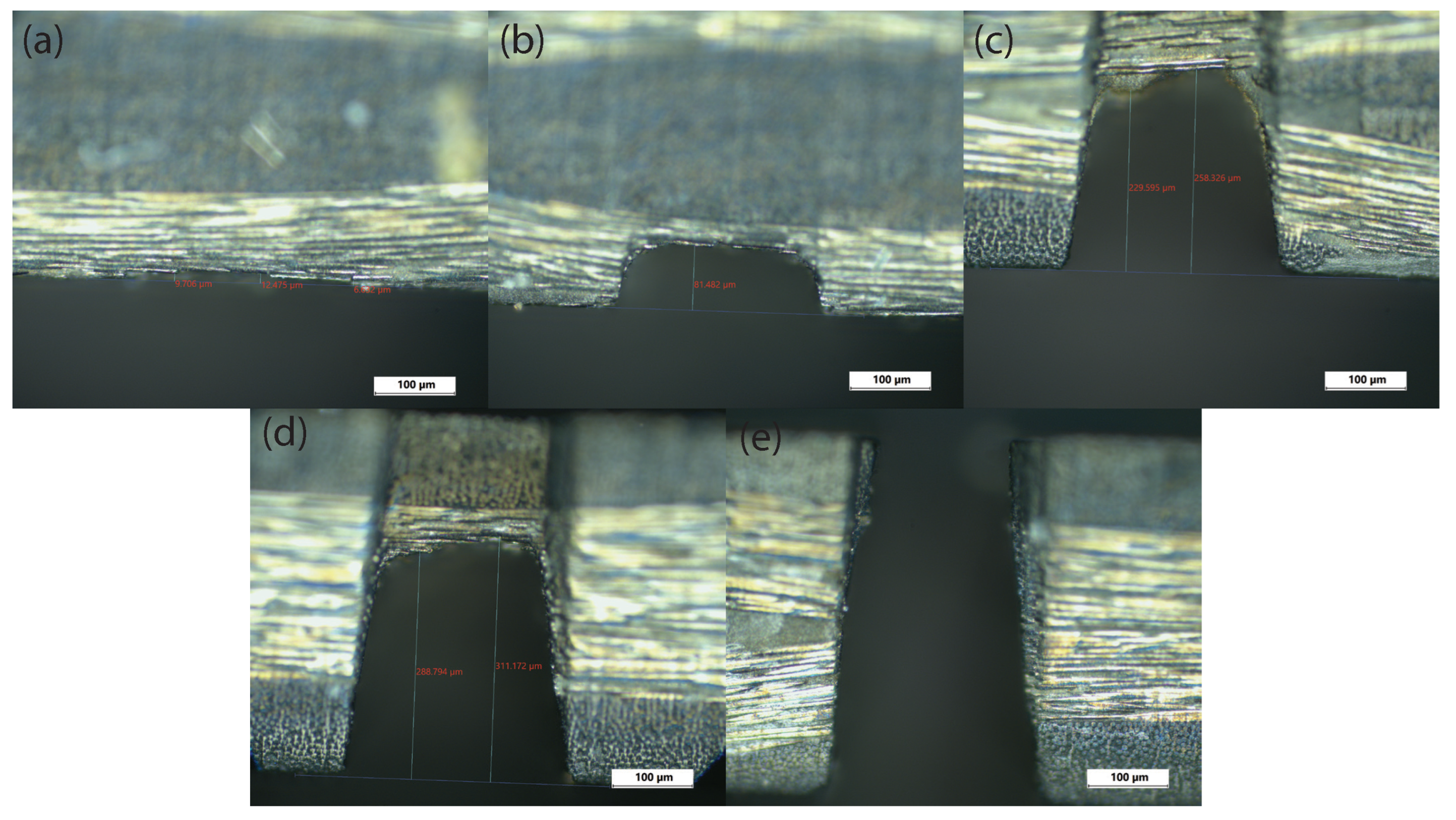
We proceeded to use these parameters to cut a 0.5 mm thick CFRP sample. Our idea of using this set of ablation parameters for cutting was based on the experiments described above, where we compared the results of the two approaches. To cut the CFRP material, we chose to ablate a 0.25 mm wide trench by scanning the laser beam multiple times along the cut line using a scan head with the f-theta lens. To achieve full separation, we first determined the number of scans required to ablate through the sample. We focused the laser on the surface of the sample and we made several ablation tracks. We increased the number of scans by 10 in each track until we saw a through channel. We then used these parameters to ablate across these trenches and captured the cross-section pictures using an optical microscope. The results are shown in Figure 6. After 10, 20 and 30 repetitions, we measured the depths of the trenches to be around 80 μm, 230 μm and 290 μm, respectively. We determined that a full cut of the sample was achieved when 40 consecutive scans were used.
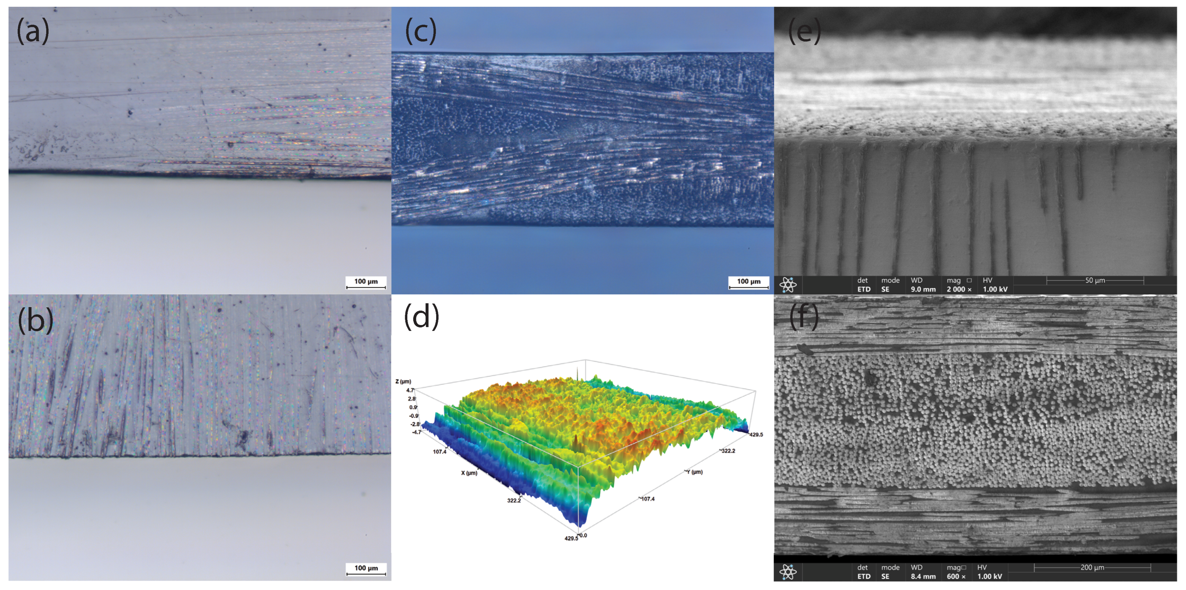
We then continued by making another cut, which we evaluated using an optical microscope and profiler. In Figure 7a,b, the top (laser incidence) and bottom sides of the cut are shown, respectively. There was no visible heat-affected zone on either side, and the black shadow along the edge in (a) was visible because of the taper present on the edge. Figure 7c shows the cross-section of the cut. Here, we note that using the most efficient parameters from Figure 2c and Figure 4a, we achieved CFRP ablation with a barely recognizable HAZ and no significant sample deformation. This is an indication of good cutting quality. The measured roughness value (Sa) of the cut cross-section (Sa: 1.27 μm, Figure 7d) was very similar to the Sa of the processed CFRP surface (see Figure 3g). To improve the HAZ recognition, we took SEM images from the same scan, where we could see only an 7–8 μm HAZ, which was indicated by a slightly molten edge (Figure 7e). We did not detect any delamination, tearing or disorder of the fibers introduced by the cutting process (Figure 7f). The discolored area in the microscope image correlated with the recognized HAZ in the SEM image. We note that in this way, we could only detect the HAZ on the surface of the sample. Overall, this set of parameters worked well for the cutting of CFRP; however, it might not be the most optimal because different pulse durations and overlaps were not tested at higher speeds and larger spot sizes. Also, other conditions, for example, a selected scanning pattern or a selected kerf width, can affect the process and are not covered here.
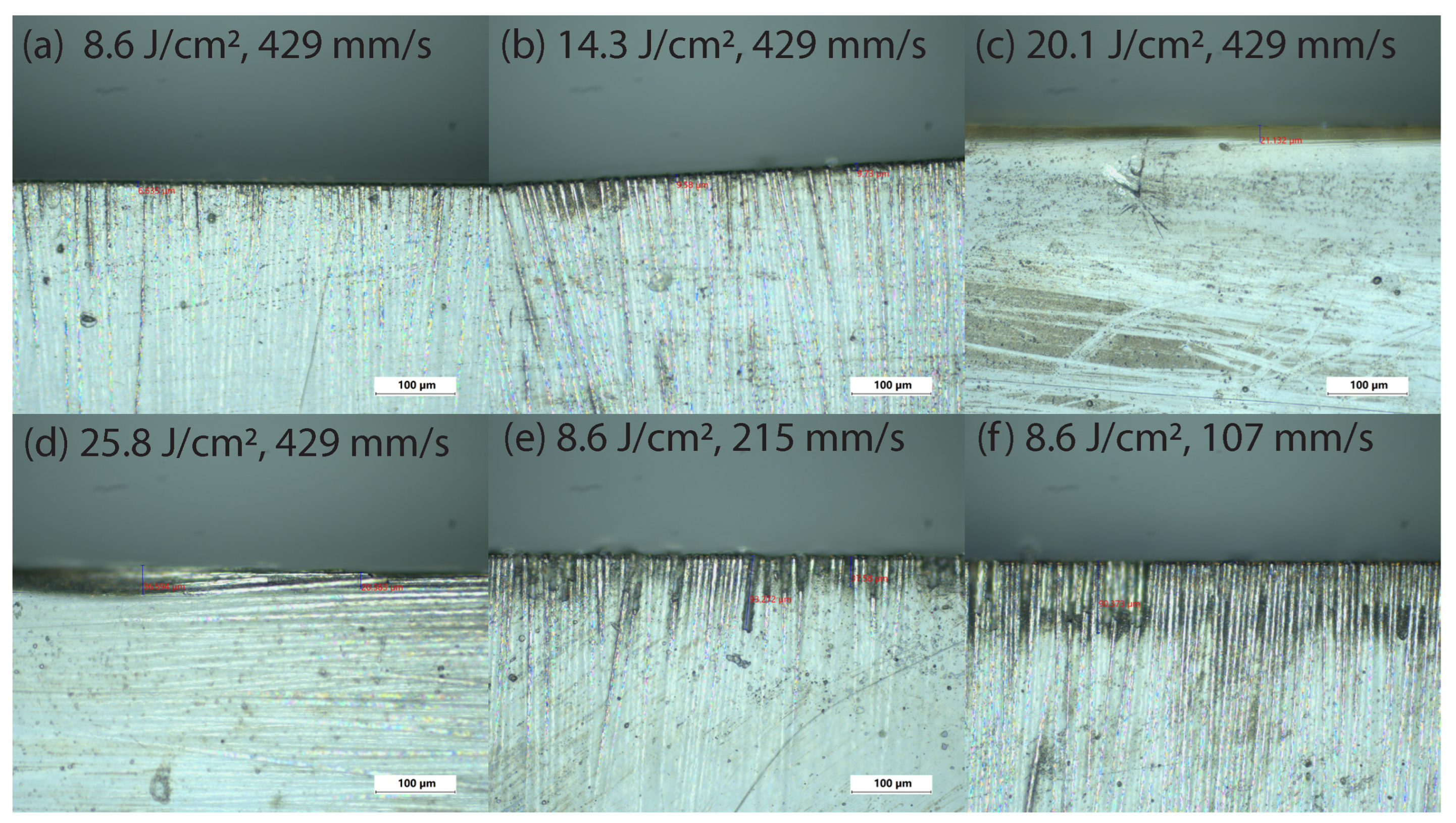
To further investigate the evolution of the HAZ depending on the laser parameters, we produced cuts using several parameters that would increase the total energy input. First, we varied the fluence. For this, we set the laser frequency to 100 kHz and changed the scanning speed to 429 mm / s . We did this because we were limited by the maximum power of our laser (6 W) and decreasing scanning speed and laser frequency together allowed for maintaining the same pulse overlap as in the experiment described above. Figure 8a shows a minimal HAZ (up to 10 μm) when the laser fluence was set to 8.6 J / cm 2 . The HAZ increased slightly once the laser fluence was set to 14.3 J / cm 2 , but was still low (less than 10 μm, Figure 8b). Some larger discoloration spots started to appear. When the fluence increased further, a clear discoloration was visible 20 μm from the edge (see Figure 8c,d). The total energy input could also be increased by reducing the scanning speed. The results of this outcome are illustrated in Figure 8e,f. In both of these cases, the HAZ was clearly visible as the darkened area around the sample edge. We measured around 40 μm HAZ after cutting the sample using a two times slower scan speed (Figure 8e), and around 90 μm after the scan speed was reduced by four times (Figure 8f). These results confirm that the ablation parameters determined in Section 2.2 and Section 2.3 were suitable for the cutting of CFRP with a negligible HAZ.

3. Conclusions

We optimized the pulse-to-pulse distance for our femtosecond processing setup, where we obtained the best pulse-to-pulse distance of 1.4 μm, which corresponded to an 82% pulse-to-pulse overlap for our obtained best pulse duration and fluence. The parameters of the optimized laser ablation were neither extraordinary nor at the edge of the laser system’s capabilities. As we predicted, the best pulse duration was the shortest available pulse duration of our femtosecond laser of 190 fs for the “cold” laser processing performance. The most efficient laser fluence for ablation using our focusing conditions was 8.59 J / cm 2 . Using these conditions, it was possible to avoid excess laser energy supply to the material surface, with further energy transfer deeper into the bulk. We estimated the laser system parameters and configuration for high-speed processing that were easily achievable. With a new laser system setup, we demonstrated a high-speed (858 mm / s ) multi-scan ablation process that could cut the CFRP with a low side wall roughness of 1.27 μm. The results of this research show the possibility of an industrial application of femtosecond lasers for precise CFRP ablation with a negligible HAZ and its applicability for the cutting of this material.

Author Contributions

Conceptualization, E.V., P.Š. and O.M.; methodology, E.V., P.Š. and O.M.; software, P.Š. and O.U.; validation, E.V.; formal analysis, S.O.; investigation, P.Š., O.U., J.M., A.B. and D.B.; resources, P.Š., O.U. and S.O.; data curation, P.Š., O.U. and J.M.; writing—original draft preparation, P.Š.; writing—review and editing, P.Š., E.V., O.M. and S.O.; visualization, P.Š., O.U. and J.M.; supervision, E.V.; project administration, E.V. and O.M.; funding acquisition, E.V. and O.M. All authors read and agreed to the published version of this manuscript.

Funding

This research and APC were funded by the Research Council of Lithuania, grant number P-LU-24-46, and by the Ministry of Education and Science of Ukraine, agreement number M/50-2024, reg. number 0124U003362.

Institutional Review Board Statement

Not applicable.

Informed Consent Statement

Not applicable.

Data Availability Statement

Data will be made available upon request.

Conflicts of Interest

The authors declare no conflicts of interest.

Abbreviations

The following abbreviations are used in this manuscript:
CFRPCarbon-fiber-reinforced plastic
HAZHeat-affected zone
fsfemtosecond

References

  1. Che, D.; Saxena, I.; Han, P.; Guo, P.; Ehmann, K.F. Machining of carbon fiber reinforced plastics/polymers: A literature review. J. Manuf. Sci. Eng. 2014, 136, 034001. [Google Scholar] [CrossRef]
  2. Wang, Z.; Ma, Y.; Yuan, B.; Wu, C.; Li, C.; Sun, S. Development of laser processing carbon-fiber-reinforced plastic. Sensors 2023, 23, 3659. [Google Scholar] [CrossRef] [PubMed]
  3. Soutis, C. Carbon fiber reinforced plastics in aircraft construction. Mater. Sci. Eng. A 2005, 412, 171–176. [Google Scholar] [CrossRef]
  4. Pecat, O.; Rentsch, R.; Brinksmeier, E. Influence of milling process parameters on the surface integrity of CFRP. Procedia CIRP 2012, 1, 466–470. [Google Scholar] [CrossRef]
  5. Mulqueen, D.W.; Sattar, S.; Kravchenko, O.G. Mechanical and thermal properties of carbon fiber epoxy composite with interlaminar graphene at elevated temperature. Compos. Part B Eng. 2023, 255, 110609. [Google Scholar] [CrossRef]
  6. Torokhov, V.G.; Chukov, D.I.; Tcherdyntsev, V.V.; Sherif, G.; Zadorozhnyy, M.Y.; Stepashkin, A.A.; Larin, I.I.; Medvedeva, E.V. Mechanical and thermophysical properties of carbon fiber-reinforced polyethersulfone. Polymers 2022, 14, 2956. [Google Scholar] [CrossRef]
  7. Hegde, S.; Shenoy, B.S.; Chethan, K. Review on carbon fiber reinforced polymer (CFRP) and their mechanical performance. Mater. Today Proc. 2019, 19, 658–662. [Google Scholar] [CrossRef]
  8. Seo, J.; Kim, D.C.; Park, H.; Kang, Y.S.; Park, H.W. Advancements and challenges in the carbon fiber-reinforced polymer (CFRP) trimming process. Int. J. Precis. Eng. Manuf.-Green Technol. 2024, 11, 1341–1360. [Google Scholar] [CrossRef]
  9. Sayam, A.; Rahman, A.M.; Rahman, M.S.; Smriti, S.A.; Ahmed, F.; Rabbi, M.F.; Hossain, M.; Faruque, M.O. A review on carbon fiber-reinforced hierarchical composites: Mechanical performance, manufacturing process, structural applications and allied challenges. Carbon Lett. 2022, 32, 1173–1205. [Google Scholar] [CrossRef]
  10. Abedin, F.; Kalla, D.K. Review on heat affected zone (HAZ) in laser machining. In Proceedings of the 6th Annual GRASP Symposium, Wichita, KS, USA, 23 April 2010; pp. 63–64. [Google Scholar]
  11. Oh, S.; Lee, I.; Park, Y.B.; Ki, H. Investigation of cut quality in fiber laser cutting of CFRP. Opt. Laser Technol. 2019, 113, 129–140. [Google Scholar] [CrossRef]
  12. Staehr, R.; Wippo, V.; Jaeschke, P.; Kaierle, S. Laser microdrilling of CFRP with a nanosecond-pulsed high-power laser. J. Laser Appl. 2022, 34, 042028. [Google Scholar] [CrossRef]
  13. Niino, H.; Kawaguchi, Y.; Sato, T.; Narazaki, A.; Kurosaki, R.; Muramatsu, M.; Harada, Y.; Anzai, K.; Wakabayashi, K.; Nagashima, T.; et al. Laser cutting of carbon fiber reinforced thermo-plastic (CFRTP) by IR laser irradiation. J. Laser Micro Nanoeng. 2014, 9, 180. [Google Scholar] [CrossRef]
  14. Bin, D.; Juan, Z.; Dawei, W.; Yiyuan, Z.; Leran, Z.; Rui, L.; Chen, X.; Shunli, L.; Zihang, Z.; Hao, W.; et al. Femtosecond laser micromachining optical devices. Opto-Electron. Eng. 2023, 50, 220073. [Google Scholar]
  15. Feng, J.; Wang, J.; Liu, H.; Sun, Y.; Fu, X.; Ji, S.; Liao, Y.; Tian, Y. A Review of an Investigation of the Ultrafast Laser Processing of Brittle and Hard Materials. Materials 2024, 17, 3657. [Google Scholar] [CrossRef] [PubMed]
  16. Chen, M.; Guo, B.; Jiang, L.; Liu, Z.; Qian, Q. Analysis and optimization of the heat affected zone of CFRP by femtosecond laser processing. Opt. Laser Technol. 2023, 167, 109756. [Google Scholar] [CrossRef]
  17. Sugioka, K.; Cheng, Y. Ultrafast lasers—Reliable tools for advanced materials processing. Light. Sci. Appl. 2014, 3, e149. [Google Scholar] [CrossRef]
  18. Malinauskas, M.; Žukauskas, A.; Hasegawa, S.; Hayasaki, Y.; Mizeikis, V.; Buividas, R.; Juodkazis, S. Ultrafast laser processing of materials: From science to industry. Light. Sci. Appl. 2016, 5, e16133. [Google Scholar] [CrossRef] [PubMed]
  19. Phillips, K.C.; Gandhi, H.H.; Mazur, E.; Sundaram, S. Ultrafast laser processing of materials: A review. Adv. Opt. Photonics 2015, 7, 684–712. [Google Scholar] [CrossRef]
  20. Lei, S.; Zhao, X.; Yu, X.; Hu, A.; Vukelic, S.; Jun, M.B.; Joe, H.E.; Yao, Y.L.; Shin, Y.C. Ultrafast laser applications in manufacturing processes: A state-of-the-art review. J. Manuf. Sci. Eng. 2020, 142, 031005. [Google Scholar] [CrossRef]
  21. Juodkazis, S.; Kondo, T.; Mizeikis, V.; Matsuo, S.; Misawa, H.; Vanagas, E.; Kudryashov, I. Microfabrication of three-dimensional structures in polymer and glass by femtosecond pulses. arXiv 2002, arXiv:physics/0205025. [Google Scholar]
  22. Vanagas, E.; Kudryashov, I.; Tuzhilin, D.; Juodkazis, S.; Matsuo, S.; Misawa, H. Surface nanostructuring of borosilicate glass by femtosecond nJ energy pulses. Appl. Phys. Lett. 2003, 82, 2901–2903. [Google Scholar] [CrossRef]
  23. Gaizauskas, E.; Vanagas, E.; Jarutis, V.; Juodkazis, S.; Mizeikis, V.; Misawa, H. Discrete damage traces from filamentation of Gauss-Bessel pulses. Opt. Lett. 2006, 31, 80–82. [Google Scholar] [CrossRef] [PubMed]
  24. Myronyuk, O.; Raks, V.A.; Baklan, D.; Vasyliev, G.; Vanagas, E.; Kurdil, N.; Sivolapov, P. Water repellent coatings with hierarchal structures obtained on anodized aluminum with femtosecond laser ablation. Appl. Nanosci. 2021, 12, 523–531. [Google Scholar] [CrossRef]
  25. Takesada, M.; Vanagas, E.; Tuzhilin, D.; Kudryashov, I.; Suruga, S.; Murakami, H.; Sarukura, N.; Matsuda, K.; Mononobe, S.; Saiki, T.; et al. Micro-character printing on a diamond plate by femtosecond infrared optical pulses. Jpn. J. Appl. Phys. 2003, 42, 4613. [Google Scholar] [CrossRef]
  26. Lin, X.; Chen, H.; Jiang, S.; Zhang, C. A Coulomb explosion theoretical model of femtosecond laser ablation materials. Sci. China Technol. Sci. 2012, 55, 694–701. [Google Scholar] [CrossRef]
  27. Zhao, X.; Shin, Y.C. Coulomb explosion and early plasma generation during femtosecond laser ablation of silicon at high laser fluence. J. Phys. D Appl. Phys. 2013, 46, 335501. [Google Scholar] [CrossRef]
  28. Mahan, G. Relaxation time of electron-phonon systems. J. Phys. Chem. Solids 1970, 31, 1477–1484. [Google Scholar] [CrossRef]
  29. Jiang, J.; Saito, R.; Grüneis, A.; Dresselhaus, G.; Dresselhaus, M. Electron–phonon interaction and relaxation time in graphite. Chem. Phys. Lett. 2004, 392, 383–389. [Google Scholar] [CrossRef]
  30. Elsayed-Ali, H.; Norris, T.; Pessot, M.; Mourou, G. Time-resolved observation of electron-phonon relaxation in copper. Phys. Rev. Lett. 1987, 58, 1212. [Google Scholar] [CrossRef] [PubMed]
  31. Sidorova, M.; Semenov, A.; Hübers, H.W.; Ilin, K.; Siegel, M.; Charaev, I.; Moshkova, M.; Kaurova, N.; Goltsman, G.N.; Zhang, X.; et al. Electron energy relaxation in disordered superconducting NbN films. Phys. Rev. B 2020, 102, 054501. [Google Scholar] [CrossRef]
  32. Sjakste, J.; Vast, N.; Barbarino, G.; Calandra, M.; Mauri, F.; Kanasaki, J.; Tanimura, H.; Tanimura, K. Energy relaxation mechanism of hot-electron ensembles in GaAs: Theoretical and experimental study of its temperature dependence. Phys. Rev. B 2018, 97, 064302. [Google Scholar] [CrossRef]
  33. Wang, F.; Shan, J.; Knoesel, E.; Bonn, M.; Heinz, T.F. Electronic charge transport in sapphire studied by optical-pump/THz-probe spectroscopy. In Proceedings of the Ultrafast Phenomena in Semiconductors and Nanostructure Materials VIII, San Jose, CA, USA, 30 June 2004; Volume 5352, pp. 216–221. [Google Scholar]
  34. Yang, J.A.; Parham, S.; Dessau, D.; Reznik, D. Novel electron-phonon relaxation pathway in graphite revealed by time-resolved Raman scattering and angle-resolved photoemission spectroscopy. Sci. Rep. 2017, 7, 40876. [Google Scholar] [CrossRef] [PubMed]
  35. Köhler, C. Phonon-Induced Ultrafast Relaxation Processes and Local Enhancement of Electric Fields. Ph.D. Thesis, Technischen Universität Berlin, Berlin, Germany, 2016. [Google Scholar]
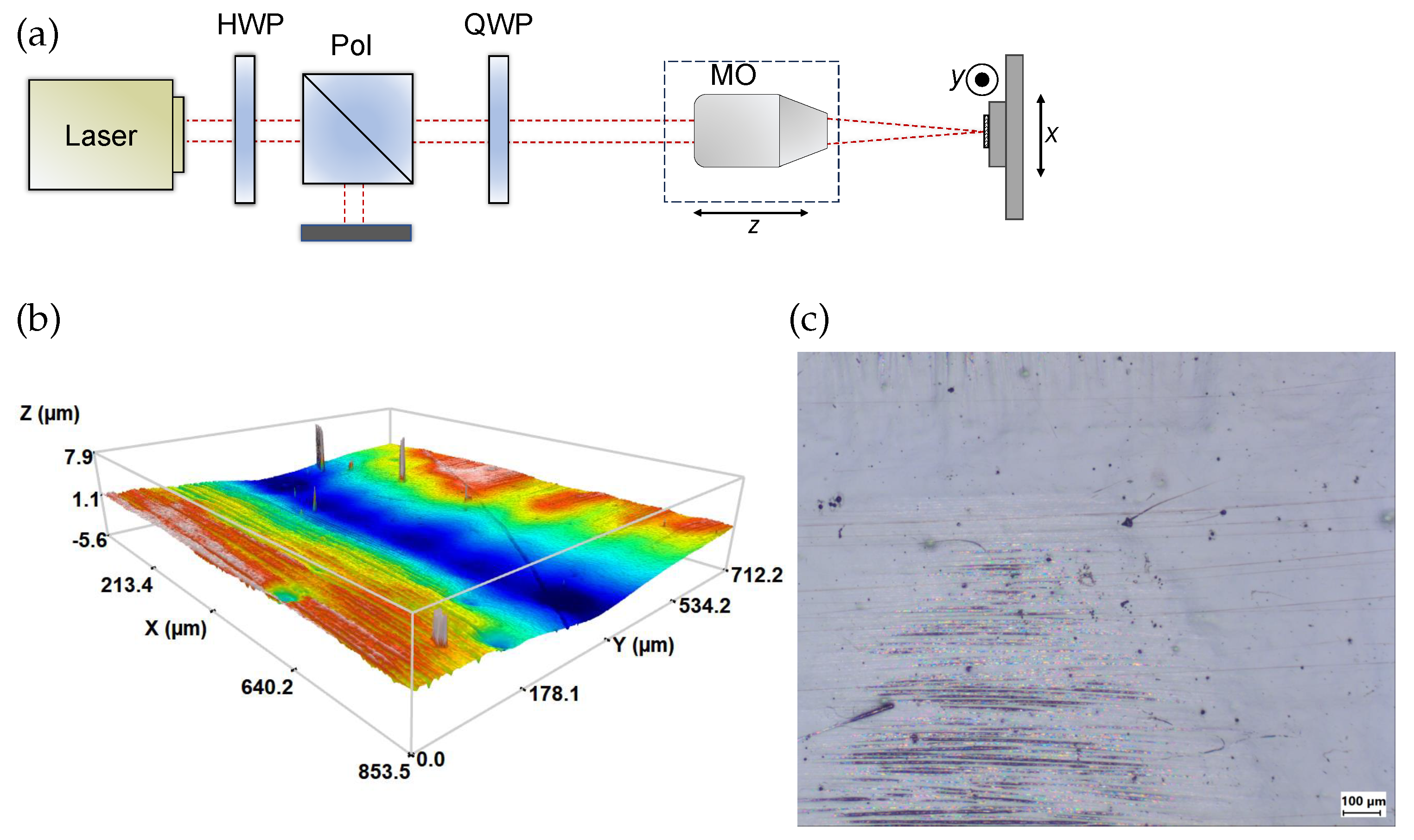
Figure 1. (a) Optical setup for the fabrication of the CFRP. (b) Profile of the initial sample surface. (c) Microscope picture of the initial sample surface.
Coatings 15 00104 g001
Figure 2. Energy specific volumes for various pulse-to-pulse distances in a hatch line: (a) 0.2 μm, 0.4 μm and 0.6 μm, (b) 0.8 μm, 1 μm and 1.2 μm, (c) 1.4 μm, 1.6 μm and 1.8 μm. A pulse duration of 0.19 ps was used.
Coatings 15 00104 g002
Figure 3. Surface profiles and roughnesses measured at the best performing fluence for every tested p.
Coatings 15 00104 g003
Figure 4. Ablation efficiencies for various pulse durations: (a) 0.19 ps , 0.5 ps and 1 ps , (b) 2 ps , 4 ps and 8 ps . The pulse-to-pulse distance was set to 1.4 μm.
Coatings 15 00104 g004
Figure 5. Surface profiles and roughness measured at the best performing fluence for every tested pulse duration τ when p = 1.4 μm.
Coatings 15 00104 g005
Figure 6. Microscope pictures of the cross-section of the ablated trenches. The number of scans used were as follows: (a) 1, (b) 10, (c) 20, (d) 30 and (e) 40.
Coatings 15 00104 g006
Figure 7. Microscope pictures of the sample edge after cutting the CFRP with a fs laser and a scan head with an f-theta lens. Top and bottom surfaces are shown in (a) and (b), respectively. (c) Microscope picture of the cross-section of the cut, (d) profile of the cross-section of the cut, (e) SEM picture of the top surface of the edge and (f) SEM picture of the cross-section of the edge.
Coatings 15 00104 g007
Figure 8. Microscope pictures of the top surface of the sample edge after cutting the CFRP with a fs laser.
Coatings 15 00104 g008
Disclaimer/Publisher’s Note: The statements, opinions and data contained in all publications are solely those of the individual author(s) and contributor(s) and not of MDPI and/or the editor(s). MDPI and/or the editor(s) disclaim responsibility for any injury to people or property resulting from any ideas, methods, instructions or products referred to in the content.