Article

Effect of Polytetrafluoroethylene Coating on Corrosion Wear Properties of AZ31 Magnesium Alloy by Electrophoretic Deposition

1
School of Materials and Metallurgy, Guizhou University, Guiyang 550025, China
2
School of Materials and Construction Engineering, Guizhou Normal University, Guiyang 550025, China
3
Guizhou Province Dual Carbon and New Energy Technology Innovation and Development Research Institute, Guiyang 550025, China
*
Author to whom correspondence should be addressed.
Coatings 2024, 14(6), 664; https://doi.org/10.3390/coatings14060664
Submission received: 11 April 2024 / Revised: 5 May 2024 / Accepted: 8 May 2024 / Published: 24 May 2024
(This article belongs to the Special Issue Thin-Film Synthesis, Characterization and Properties)

Abstract

:
In this study, we aim to enhance the corrosion and wear resistance of AZ31 magnesium alloy using electrophoretic deposition (EPD) technology to apply a hydrophobic polytetrafluoroethylene (PTFE) coating. Polyethyleneimine (PEI) serves as a charged dispersant, facilitating uniform deposition of PTFE particles on the alloy surface. Results demonstrate a significant reduction in corrosion current density (from 67.5 μA/cm2 to 5.2 μA/cm2) and improved wear resistance (wear volume decreased from 0.24167 mm3 to 0.00167 mm3) in a 3.5 wt% NaCl solution compared to uncoated alloy. Moreover, the friction coefficient of the coated sample decreases. These findings underscore the potential of nano-PTFE coatings prepared via EPD in enhancing AZ31 magnesium alloy’s corrosion and wear resistance, providing a foundation for future protective coating design and optimization.

1. Introduction

Due to their advantages of high specific strength, excellent electrical and thermal conductivity, damping, electromagnetic shielding, and biocompatibility, AZ31 magnesium (Mg) alloy shows great application potential in the fields of automobile, computer, communication, aerospace, and medicine [1,2,3]. However, the lively nature and low strength of Mg alloys make them susceptible to oxidation, electrochemical corrosion, and wear during service, which greatly limits their application range. Although AZ31 Mg alloy can develop an oxidation protective film in a natural environment, its loose and porous structure fails to provide adequate anti-wear and corrosion protection, which leads to a further decrease in corrosion resistance under harsh conditions. Therefore, improving the surface hardness, wear resistance, and corrosion resistance of AZ31 Mg alloy is the key to expanding its application range and solving the current limitations.
Generally, there are two main ways to improve the properties of the AZ31 Mg alloy: the first method is doping Ca, Mn, and some rare earth elements into the AZ31 Mg alloy to create a new alloy type or altering the microstructure of magnesium alloy through heat treatment, thereby improving their properties [4,5,6]. For example, Jiang et al. developed a protective film containing Ce by adding Ce2+ to the coating [7]. The second method employs surface treatment technologies to generate a film with desired properties on the surface of AZ31 magnesium alloy, including micro-arc oxidation, hydrothermal treatment, and chemical conversion [8,9,10]. Compared to the former method, surface treatment technology offers universality and diversity, making it a crucial means to enhance magnesium alloy properties.
Electrophoretic deposition (EDP) is an electrochemical method employed for coating preparation [11], known for its simple process, environmental friendliness, and low cost [12,13,14]. The crucial aspect of EDP is that its particles possess an electric charge on their surfaces, allowing them to form a stable suspension that moves directionally under the influence of an electric field [15]. Polytetrafluoroethylene (PTFE) is widely used in coatings for its excellent resistance to metal wear, and thus applications in fields of electronic packaging, electrical insulation, and military uses [16]. It is effective in combining electrophoretic deposition and plasma electrolytic oxidation to create a PTFE composite coating on an aluminum alloy substrate [17]. For instance, Zhao and Liu et al. have successfully prepared PTFE coatings on stainless steel by using EDP with different additives, and their Tafel and impedance plots of stainless steel demonstrate that PTFE coatings indeed improve the corrosion resistance property [18,19,20,21]. Despite the widespread utilization of PTFE coatings for their remarkable anti-corrosion properties [22,23,24], there is limited research on using EDP to prepare PTFE coatings with different thicknesses, thus improving the corrosion and wear resistance of AZ31 magnesium alloy.
Consequently, we aim to utilize EDP to apply a hydrophobic PTFE coating onto the surface of the magnesium alloy, thereby enhancing its wear and corrosion resistance properties. As a result, we successfully improved the corrosion resistance of the alloy by preparing PTFE coating, enhancing its wear resistance and friction coefficient. Furthermore, our experimental results confirm that the PTFE nano-coating prepared by EPD technology holds significant promise in enhancing the corrosion resistance and wear resistance of AZ31 magnesium alloy.

2. Materials and Methods Applied

2.1. Materials

The PTFE herein with particle size less than 5 µm are from Aladdin’s official website; PEI (molecular weight 10,000) is from Shanghai Aladdin Biochemical Technology Co., Ltd. (Shanghai, China); ethanol (analytical grade higher than 99.7%) and concentrated hydrochloric acid, from Chongqing Chuandong Chemical (Group) Co., Ltd. (Chongqing, China); and electrophoretic deposition instrument (DYY-3C), from Beijing Liuyi Biotechnology Co., Ltd. (Beijing, China). All chemical reagents herein are analytical pure reagents.

2.2. Preparation of PTFE Film

PTFE nanoparticles under 5 µm in size, along with cationic surfactant (PEI, 10 mg/L), and electrolyte (HCl, 15 mg/L) are combined in an ethanol solution to create a suspension. The scanning electron microscope (ZEISS Sigma 300) micrograph and scanner electron microscopy (SEM) with energy-dispersive spectroscopy (EDS) plot of the PTFE nanoparticles are shown in Figure 1a and Figure 1b, respectively. It indicates that the PTFE particles represent an elongated elliptical morphology. In addition, Figure 1c displays the particle size distribution of the PTFE, with an average particle size of ~0.4859 µm PTFE.
Next, AZ31 Mg alloy is served as both the cathode and anode electrode and the electrodes are fixed within the device at a distance of 1 cm. After impregnating the working electrodes with a PTFE solution, the cathode undergoes deposition. Before EDP, the suspension is magnetically agitated and ultrasonically oscillated for 30 min. Then, the EDP procedure is conducted at 40 V for 5, 10, and 15 min, respectively, at 25 °C to produce films of different thicknesses. Next, the sample is dried in a vacuum oven at 70 °C for 30 min, and the PTFE is heated in a vacuum tube furnace at 270 °C for ~30 min to improve its adhesion to the substrate.

2.3. Methods Adopted for Testing

Scanner electron microscopy (SEM) results are analyzed to identify the element composition and morphological characteristics of the PTFE films, including pore density and coating evenness. The zeta potential of the dispersion is measured by the Zeta Potential Analyzer (England Malvern Zetasizer Nano ZS90). An energy-dispersive spectrometer (EDS) is used to analyze elemental distributions and identify PTFE particles on the Mg alloy substrate. Before testing, the coated surfaces are sprayed with gold. The film morphology and content are investigated by using X-ray diffraction (XRD and Rigaku MiniFlex600) and Fourier infrared spectroscopy (FTIR and Rigaku MiniFlex600) patterns. The surface morphology is analyzed by studying the 3D morphology (Shenzhen Zhongtu Instrument Co., Ltd., Shenzhen, China). An ultra-depth-of-field microscope (KEYENCE VHX-7000) is used to take the cross-sectional images of the PTFE-coated samples.

2.4. Property Testing

2.4.1. Contact Angle Testing

A contact angle tester (Beijing HARKE) is employed to measure the water contact angle (WCA). Immediately after releasing water droplets, photographs of the water contact angle are taken, with at least five measurements conducted for each substrate.

2.4.2. Corrosion Resistance Testing

The corrosion properties of PTFE coatings are examined through polarization experiments and electrochemical impedance spectroscopy (EIS) by using a Shanghai Chenhua CHl760e workstation with Pt and SCE (reference saturated calomel electrode) as the auxiliary electrodes. During electrochemical tests, each working electrode, with a test area of 3.02 × 10⁻¹ cm2, is immersed in a 3.5 wt% sodium chloride (NaCl) solution.

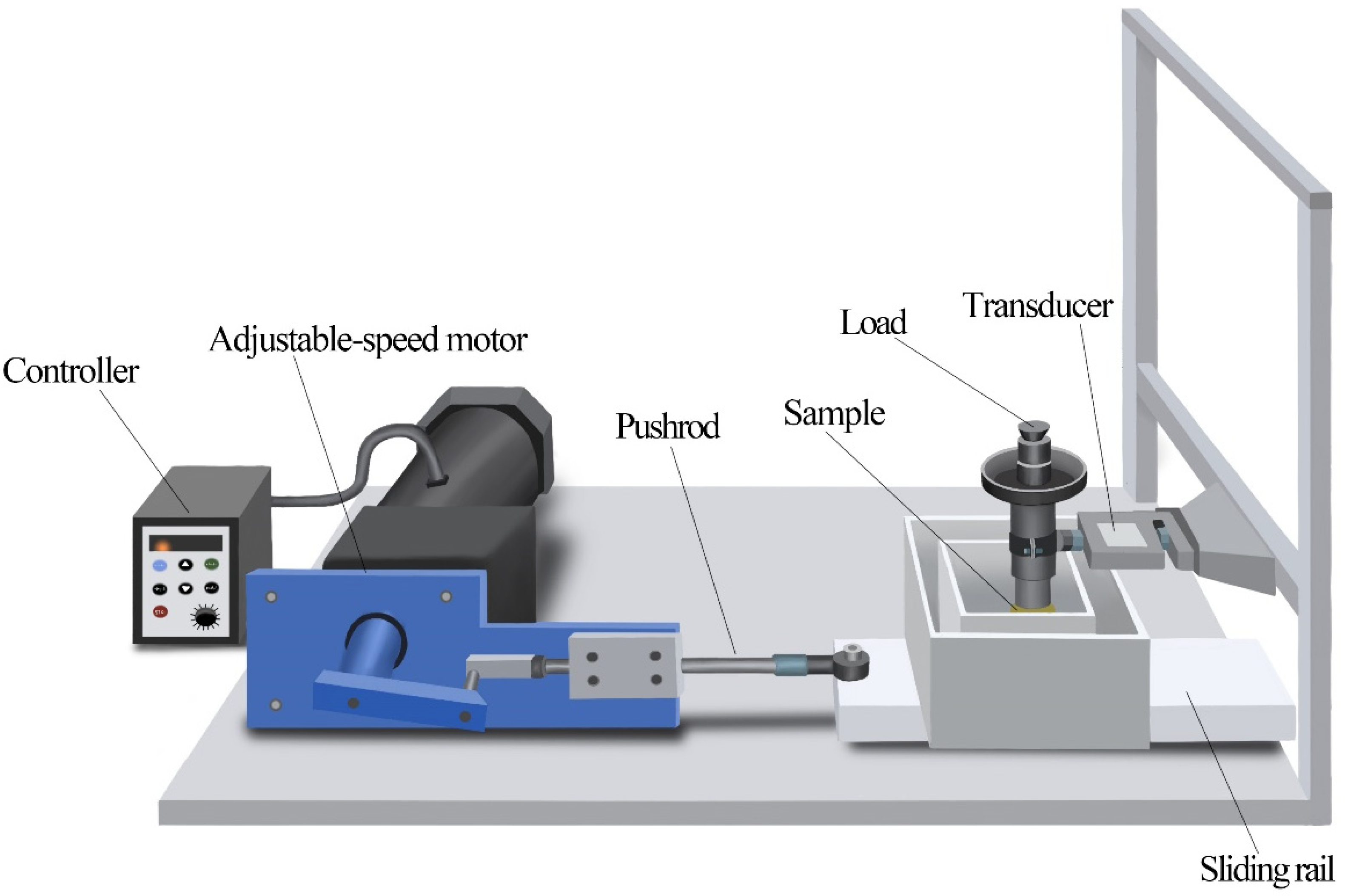
2.4.3. Abrasion Resistance Testing

Dry friction and wear tests are conducted at room temperature on a homemade reciprocating friction tester to evaluate the abrasion resistance of the PTFE film. Figure 2 displays the homemade reciprocating, it is indicating the test utilizes a 7 mm diameter Al2O3 ball as the counterpart, and the dry wear displacement is measured to be 12 mm. Both the original and surface-treated samples undergo 60 min reciprocating dry wear experiments at a frequency of 625 Hz and a load of 1 N.
A 3D profilometer (3D, Shenzhen Zhongtu Instrument Co., Ltd., Shenzhen, China) with the function of measuring weight loss is primarily utilized to measure the mass loss of both the uncoated and surface-coated samples; the mass loss of each sample is measured three times to minimize experimental errors, and the average mass loss is finally adopted.

3. Results and Discussion

3.1. Characterization of Zeta Potential

As shown in Figure 3, with only PTFE in the solution, the suspension exhibits a zeta potential of 5.73 mV, indicating neutrality. Adding PEI can react with alcohol to yield protons; however, protons are less readily released in an alcohol solution, resulting in a weakly cationic suspension [25]. When hydrochloric acid is introduced, PEI undergoes significant protonation and adsorbs PTFE particles, resulting in a zeta potential value of 33.47 mV, which indicates a strongly cationic suspension with stable particle dispersion. The amine groups protonate of PEI and become positively charged with the addition of a mild acid, as indicated in the following reaction:
P E I + H C I   P E I H + + C l
where the positively charged PEI H+ ions are absorbed into the PTFE, and thin films are formed as the positively charged PTFE particles move toward the cathode.
Table 1 summarizes the impact of various additives on solution conductivity and zeta potential. The suspension with only solvent and particles is denoted as P1, with the addition of PEI, it is denoted as P2, and with the addition of both PEI and hydrochloric acid, it is denoted as P3. It is found that the electrical conductivity (EC) of P1 is about one order of magnitude higher than that of P2 and P3. Due to PTFE particles being neutral, they lack charge in the absence of additives, resulting in low suspension conductivity and minimal particle movement, thereby precluding electrophoretic deposition [26]. The reason of conductivity of P3 is higher than that of P2 may be attributed to the addition of HCl, which increases the concentration of additives.

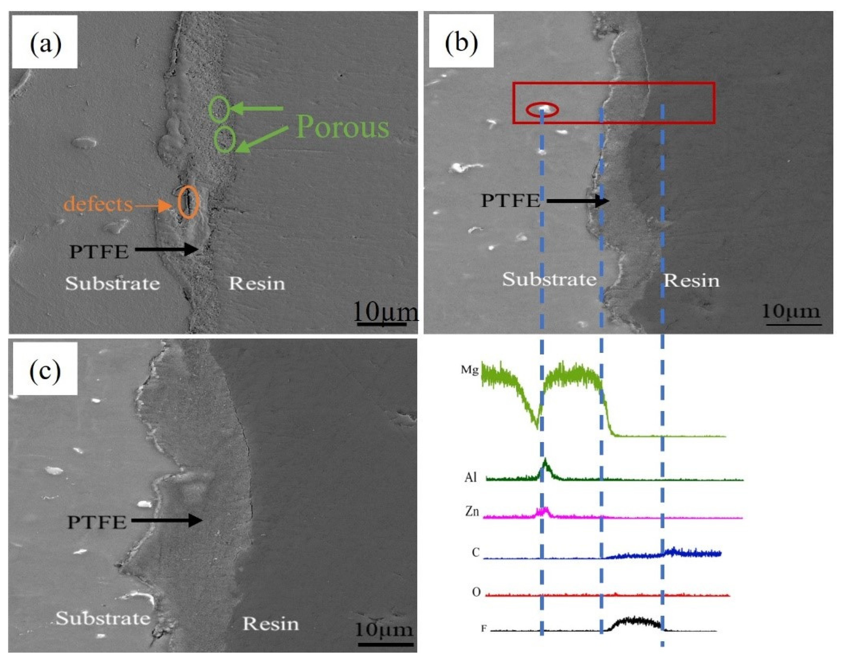
3.2. Characterization of Coatings

As shown in Figure 4, cross-sectional microscopy is used to conduct structural analysis of PTFE coatings deposited at different times. As shown in Figure 4a, microcracks and defects are observed in the PTFE coating on the substrate after 5 min of deposition. In contrast, as shown in Figure 4b,c, the PTFE coatings deposited for 10 min and 15 min showed good adhesion to the substrate. Additionally, the irregular white protrusions on the AZ31 magnesium alloy substrate are identified as compounds of Mg and Al by the mean of line scanning of the PTFE coating sample deposited for 10 min.
Cross-sectional micrographs depicting PTFE-coated AZ31 Mg alloy with varying coating thicknesses are presented in Figure 5. It is found that the interface between the PTFE coating and AZ31 Mg alloy is defect-free. As discussed earlier, the thickness of the PTFE-coated samples was varied by regulating the time of EDP during the coating process. As shown in Figure 5a–c, three different PTFE coatings exhibit mean thickness values of 9.17 μm, 13.954 μm, and 29.034 μm, respectively.
Furthermore, Figure 6a shows the XRD patterns of the coatings and the AZ31 alloy, it is found that the uncoated AZ31 Mg alloy shows diffraction peaks corresponding to the α-Mg alloy phase, while the AZ31 Mg alloy exhibits diffraction peaks of intermetallic Mg2Zn11 phases, this phenomenon may attribute to the process of heat treatment. The thin film obtained after EDP treatment comprises α-Mg and (C2F2) n, and the diffraction peaks of type C and F are observed around 2θ = 30°, 35°, 40°, and 50°, indicating successful preparation of PTFE films through EDP. It is found that MgO4 appears on the (312) crystallographic plane, which may be attributed to the oxidation of the magnesium alloy matrix. Additionally, it is found that polymers composed of C, F, and H appear on the (230) crystallographic plane.
As shown in Figure 6b, FT-IR spectra are introduced to determine the functional groups in the PTFE coatings. The peaks around 1201.85 cm−1 and 1146.37 cm−1 correspond to (-CF2-). The peaks at 552.93 cm−1 and 637.25 cm−1 are attributed to stretching vibrations of the C-F bond, while the peak at 500.75 cm−1 represents C-F absorption [27]. The presence of these functional groups confirms the successful deposition of PTFE on the AZ31 Mg alloy.

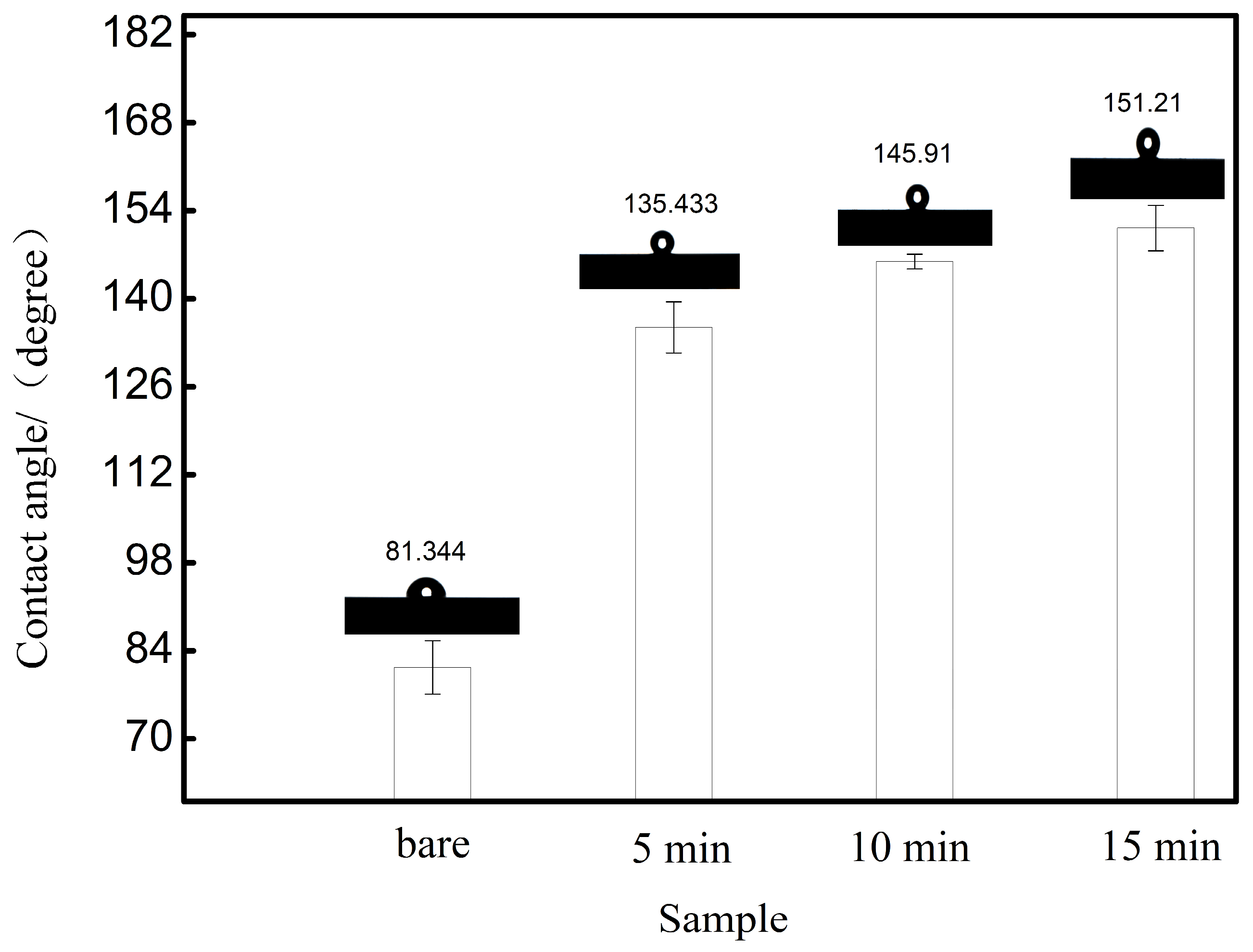
3.3. Contact Surface Micro-Nano Morphology and Contact Angle

Figure 7 shows the water contact angle on the surface of AZ31-Mg alloy and PTFE coatings. It indicates that the contact angles for the surface are 81.34°, 135.43°, 145.91°, and 151.21°, respectively, suggesting the hydrophobic nature of PTFE surfaces. Additionally, due to the existence of the C-F bond (As seen in Figure 3), the surface of the PTFE has low surface energy. When the liquid contacts the substrate, an air layer is formed, which prevents direct contact.

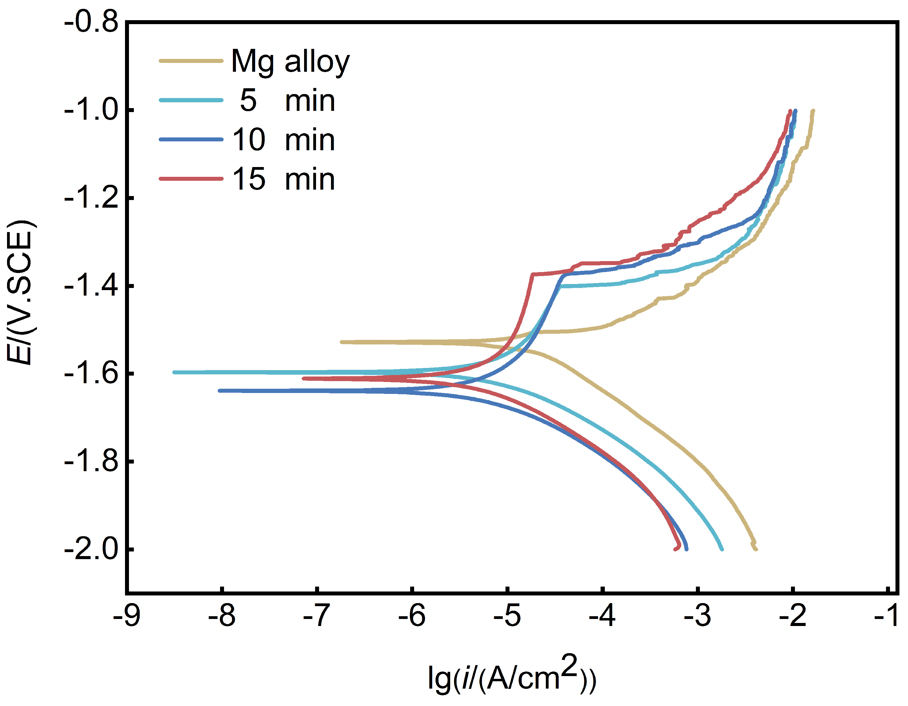
3.4. Corrosion Resistance Measurement

The Tafel polarization curves evaluate the corrosion resistance of Mg alloy with PTFE coatings, as shown in Figure 8. The corrosion potential ( E c o r r ), corrosion current density (icorr), Tafel anode slope (a), and Tafel cathode slope (c) are calculated by Cview linear fitting, and the results are summarized in Table 2. Generally, the corrosion rate can be calculated by electrochemical plot [28] or derived from Cview [29]. All samples show uniform passivation regions except for the Mg alloy, and, as shown in Figure 8, it is found that the coating deposited for 15 min demonstrates a more enduring passivation zone. Table 2 lists the electrochemical data, which demonstrates that the coated samples have enhanced the corrosion resistance ability of Mg alloys.
Additionally, as the potential increases, the surface mixed oxide film abruptly transitions to a passive film, resulting in a sharp change in current around −1.3 V. With further potential elevation, the corrosion current sharply increases, reaching the pitting or breakdown potential (around −1.3 V). Among the coated samples, the one with a deposition time of 5 min exhibits the highest corrosion current density (9.90 × 10⁻⁶ A). As the deposition time increases from 5 min to 15 min, the corrosion current density of the coated samples decreases from 16.3 µA to 5.2 µA. The increase in PTFE coating thickness partly prevents the contact between the corrosive medium and the substrate, thereby enhancing corrosion resistance.
Consequently, an equivalent circuit is employed to fit the EIS parameters. The experimental impedance spectra are obtained from the Mg alloy, which are fitted by ( R S ( R P   C P E P ). Figure 9 shows the electrochemical impedance spectra of unprotected and protected AZ31 Mg alloy, and Table 3 summarizes the values of the fitted equivalent circuit model of Mg alloy and coated Mg alloy. As shown in Figure 9d, for the coated Mg alloy, an electrical circuit model with ( R S ( C f ( R f ( C P E d l   R c t )) is proposed to replicate the experimental findings, where R f and R c t represent the outer and inner resistance of the PTFE coatings respectively. Additionally, for uneven surfaces and cracked coatings, the constant phase elements Cf and C P E d l represent the outer and inner layers of the capacitance element of coatings. RP = Rf + Rct, higher R P value indicates better corrosion resistance [30].
In order to obtain deeper insight into the impact of coating morphology and structure on corrosion resistance, the surface micrographs of PTFE-coated Mg AZ31 are studied. As shown in Figure 10, the surface of the coatings deposited for 10 min and 15 min exhibit particle flocculation, which may be attributed to the increased electrolyte concentration near the deposition electrode over time, resulting in a decrease in zeta potential and subsequent particle flocculation [26]. As the deposition time increases, the accumulation of particles becomes more pronounced. In contrast, cracks appear when the coating is deposited for 5 min. Figure 10c depicts the EDS analysis of the coating deposited for 5 min, which reveals the presence of Mg elements within the gaps. The reason may be attributed to the shorter deposition time and lower coverage of nanoparticles on the substrate, which results in partial exposure of the substrate area and the formation of microcracks. The R c t value of the coating deposited for 5 min is 124.6 Ω·cm2, which is significantly lower than that of the coatings deposited for 10 min and 15 min. This implies a higher corrosion current and lower resistance compared to coatings deposited for 10 min and 15 min, as verified by potential dynamic polarization curves and impedance data.

3.5. Wear Performance Testing

3.5.1. Coefficient of Friction

The samples undergo 1 N loads before and after applying the PTFE coating to assess the impact of coating on friction, and the friction coefficients are shown in Figure 11. Due to the soft surface of the AZ31 Mg alloy, the raw sample exhibits a much higher friction coefficient when subjected to the same load, which demonstrates that the low friction coefficient and self-lubrication of PTFE can significantly enhance the wear resistance of the AZ31 Mg alloy [31]. Compared to the raw sample, the friction curves of the PTFE coatings show less fluctuation, which indicates that the PTFE coatings can stabilize the friction. This tendency may be attributed to the PTFE in the AZ31 Mg alloy acting as a lubricant throughout the wear process.
Under the condition of 1 N stress, the raw sample has a friction coefficient of ~0.45, while the friction coefficients of the different qualities of PTFE coatings are around 0.1 before the 1800 s. However, after 1800 s, the friction coefficient of the 5 min coating steadily rises. Notably, the SEM results find a flaw in the deposited 5 min coating, and this flaw causes the destruction of the layer after nearly 1800 s of wear, which leads to an increase in the friction coefficient, and eventually stabilizes after 2500 s, with a Coefficient of Friction (COF) of approximately 0.3. In total, the friction coefficient is still lower than the original, which may be attributed to the presence of residual PTFE particles on the substrate acting as a lubricant. The 10 min and 15 min coatings demonstrate enhanced friction performance and maintain a consistent friction coefficient throughout the sliding test.

3.5.2. Abrasion Loss

Figure 12 shows the abrasion loss of uncoated and PTFE surfaces; it is found that the untreated sample shows greater abrasion loss than the coated sample under identical wear conditions. At a load of 1 N, the abrasion loss value of the raw sample is ~2.42 × 10⁻¹ mm3. In contrast, the abrasion loss values of coatings s are 1.08 × 10⁻¹ mm3, 2.67 × 10⁻³ mm3, and 1.67 × 10⁻³ mm3, respectively. Compared to the untreated sample, the abrasion losses of the 5 min deposition coating are reduced by an order of magnitude. Similarly, the abrasion losses of the 10 min and 15 min deposition coatings are reduced by two orders of magnitude, consistent with the time-friction coefficient relationship.

3.5.3. Wear Morphology

The 3D morphology and profiles of raw and coated samples after wear tests under 1 N load are shown in Figure 13. It suggests that the untreated sample shows the deepest and widest wear track (Figure 13a), which is likely due to decreased dynamic recrystallization of the Mg alloy under stress, and this is a result of the stable temperature and strain rates causing constant plastic deformation during the friction process [32]. Meanwhile, the substrate is continuously worn and the wear pits deepen as time goes on.
The grain boundary of the 5 min deposition coating is destroyed under 1 N load, while that of the 10 min and 15 min deposition coatings are both slightly affected. However, the wear resistance of the PTFE coating significantly develops and exceeds that of the AZ31 Mg alloy, and the size of the pits decreases as the coating quality improves. It is noted that the increased accumulation of PTFE debris could lead to the formation of small protrusions at the grain boundaries of the coated samples during wear.
Additionally, there is a correlation between abrasion loss and the depth and width of wear marks [33]. Combining the experimental data on friction coefficients, abrasion loss, wear morphology, and profiles reveals that the PTFE coating significantly improves the wear performance of magnesium alloys. Notably, the abrasion properties of the coatings deposited for 10 min and 15 min are quite similar, which may be attributed to their closely matched C-F content (as seen in Table 1) [34].
Figure 14 shows the wear morphology of the raw sample and PTFE coating under 1 N loads of 5 min and 10 min, respectively. It indicates the wear width and depth of the PTFE coating on the sample decreased after deposition, and both the raw samples and those with a 5 min deposition of PTFE coating exhibit protruding particles at the wear marks, which represent debris from both the raw sample and PTFE particles. Additionally, the debris is generated due to continuous contact between the Al2O3 ball and the sample surface.
Notably, the abrasion mechanism differs between the raw samples and those with PTFE deposition. Due to extensive plastic deformation of the magnesium alloy, the long and deep grooves formed on its surface, which indicates that the original sample primarily exhibits plowing wear. In addition, with the debris accumulating, abrasive and oxidation wear emerged. In contrast, the abrasion mechanism of samples with electrophoretically deposited PTFE coatings involves the self-lubricating and mechanical barrier effects. It is believed that the C-F bonds in PTFE leads to good lubrication; meanwhile, the bond strength tests indicate excellent adhesion between the coating and the substrate, imparting superior mechanical barrier properties to the coating.

3.5.4. Abrasion Mechanism

Figure 15 shows the schematic diagram of the abrasion mechanism of AZ31 Mg alloy after treatment with electrophoretic deposition of PTFE coating. Firstly, the PTFE coating significantly enhances the wear resistance of the substrate. Under a 1 N load, untreated magnesium alloy surfaces exhibit extensive and deep wear marks, which may be attributed to severe plastic deformation of the soft Mg alloy material under sustained stress. The abrasion mechanism of the original sample primarily involves plowing wear, accompanied by abrasive and oxidation wear. After electrophoretic deposition of PTFE coating, it forms a mechanical protection layer on the surface of AZ31 magnesium alloy. However, for samples with thinner coatings, both the friction coefficient and wear amount are higher compared to thicker coatings. Additionally, due to the presence of C-F bonds, its excellent self-lubricating properties reduce wear and tear. Therefore, PTFE coating effectively enhances the wear resistance of magnesium alloy materials by providing a mechanical barrier and self-lubricating effects.

3.5.5. Comparison of Properties Improved by EDP with Other Literature Reported

To verify the practicality of the PTFE coating, we compared its corrosion and wear properties improved by EDP with those reported in other literature. It was found that Wu et al. [35] achieved a maximum contact angle of 105.5° with the hydrophobic coating on the surface of the AZ31 magnesium alloy using hydrothermal treatment, whereas, in our experiment, the maximum contact angle reached 151.21°. M. Ahangari et al. [36] prepared a hydroxyapatite–carboxymethyl cellulose–graphene composite coating on AZ31 magnesium alloy by using a two-step electrophoretic deposition method; however, their polarization resistance (RP = 3589.66) is lower compared to the PTFE coating deposited for 15 min in this study. Additionally, there are reports of preparing composite coatings on the surface of AZ31 magnesium alloy using electrophoretic deposition, with a minimum friction coefficient of around 0.28 [37], while the longer deposition time PTFE coating had a friction coefficient of about 0.1 in our work. F. Zucchi et al. [38] proposed an organosilane coating on the surface of AZ31, with an impedance diameter of approximately 2000 under optimal conditions, while, in our study, the maximum impedance diameter of the PTFE coating can reach around 3600. Additionally, recent studies have focused on using electrophoretic deposition to prepare coatings on the surface of AZ31 magnesium alloy, primarily to enhance its corrosion resistance [39,40,41,42,43]. However, we utilized electrophoretic deposition to prepare a single coating that further simultaneously improved the corrosion resistance and wear resistance of AZ31 magnesium alloy. Apparently, our study successfully developed a PTFE coating with enhanced corrosion and wear resistance through EDP, and provided a new idea for future improvements in protective coating design and optimization.

4. Conclusions

In conclusion, the EDP process successfully fabricates PTFE coatings with varying qualities on AZ31 Mg alloy. The microstructure, anti-corrosion, and tribological properties of the coatings have been investigated. It is found that PEI has been successfully adsorbed on PTFE, causing the PTFE to be positively charged and deposited on the cathode substrate. Additionally, the corrosion and abrasion experiments reveal that the PTFE films provide significant protection against corrosion and wear, and the thickness of the coating affects its abrasion mechanism and corrosion resistance performance. The results are summarized as follows:
(1)
PEI can adsorb onto PTFE, and under the action of H+, PEI transforms into PEI-H+ ions, which are absorbed onto the polytetrafluoroethylene, giving PTFE a positive charge and depositing onto the cathodic substrate. By controlling different deposition times, PTFE coatings of varying thicknesses can be electrophoretically deposited on the surface of AZ31 magnesium alloy.
(2)
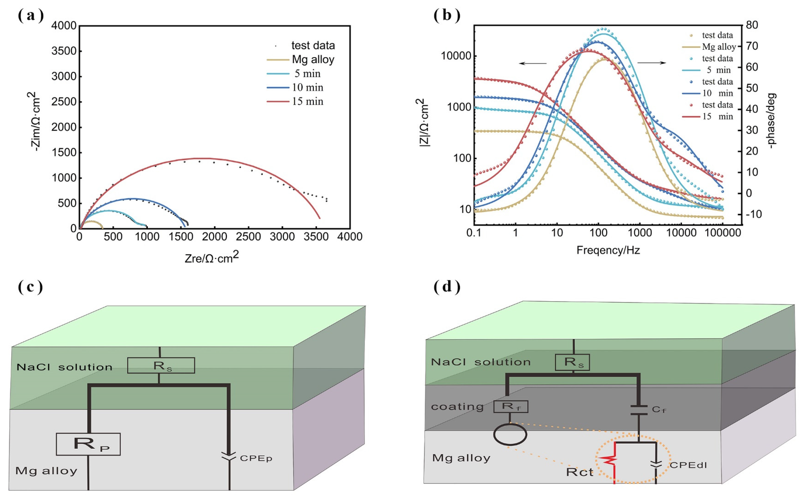
Through corrosion tests in a 3.5 wt% NaCl solution, we found that the self-corrosion current of AZ31 magnesium alloy decreased by approximately an order of magnitude after electrophoretic deposition of PTFE coating. Additionally, the impedance of AZ31 magnesium alloy with PTFE coatings deposited for 5 min, 10 min, and 15 min increased by 2-fold, 3-fold, and 7-fold, respectively, compared to the untreated sample. Combining polarization curves, electrochemical impedance, and hydrogen evolution corrosion, it can be concluded that the corrosion resistance of AZ31 magnesium alloy is improved after electrophoretic deposition of PTFE coating.
(3)
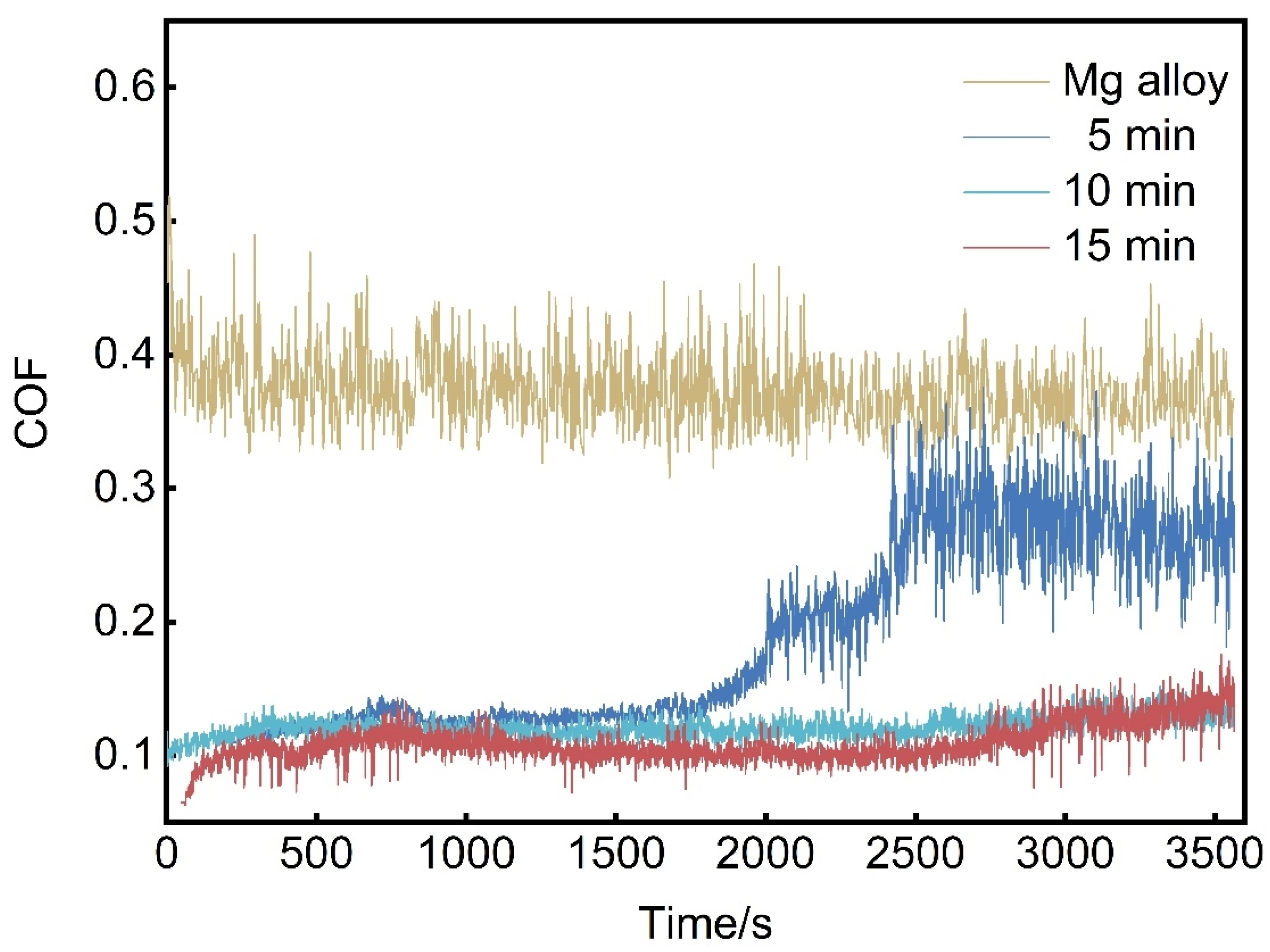
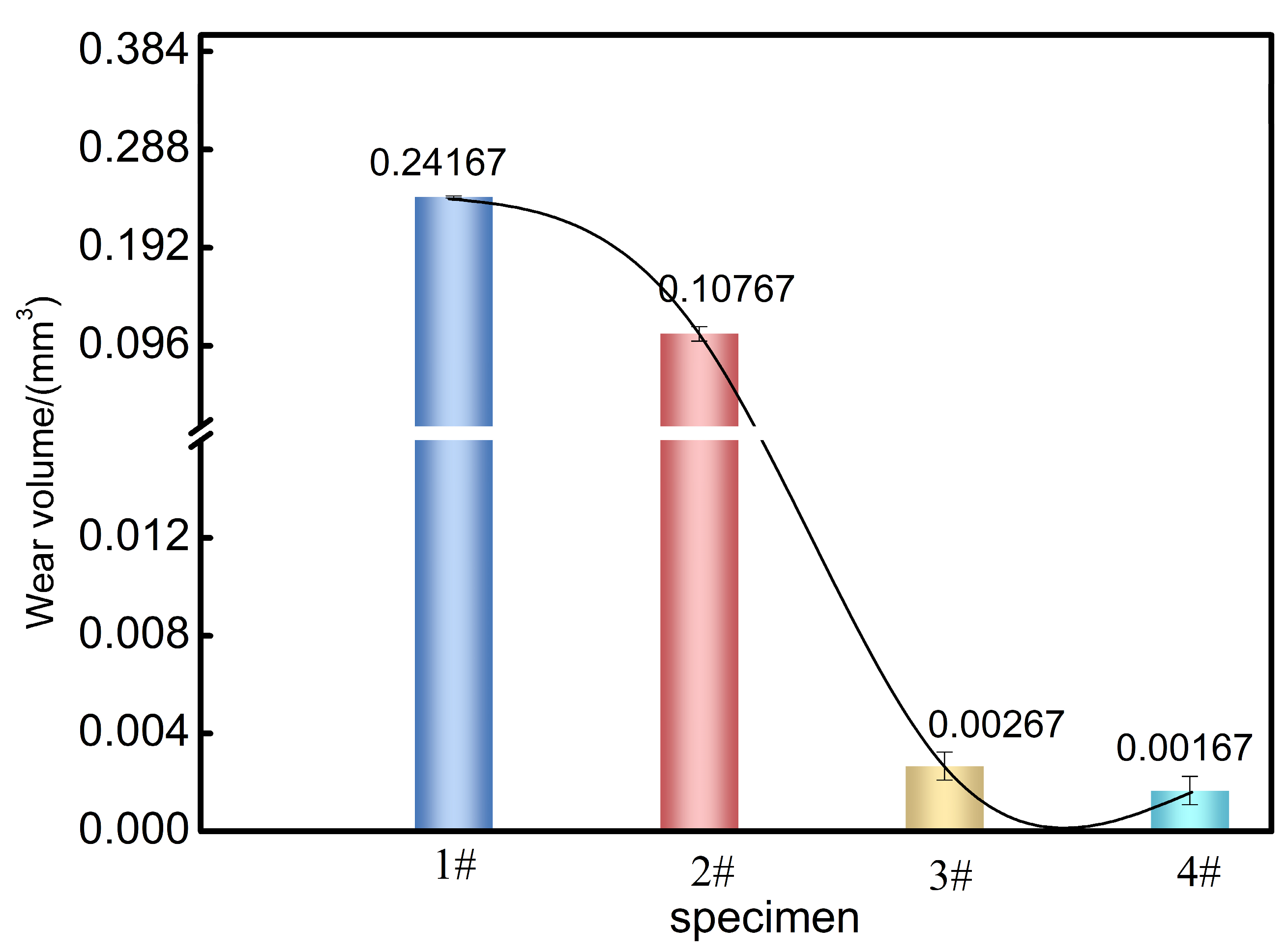
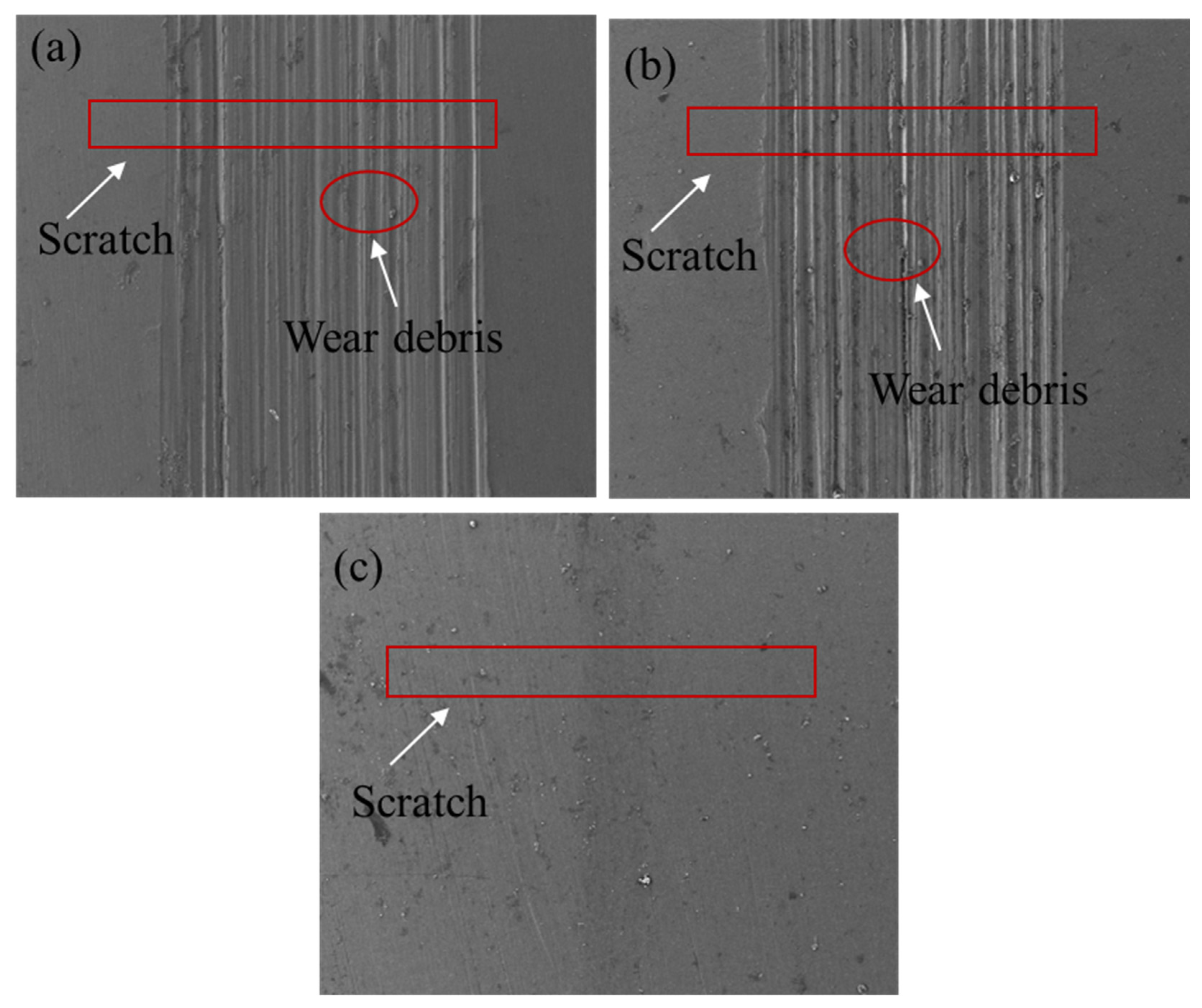
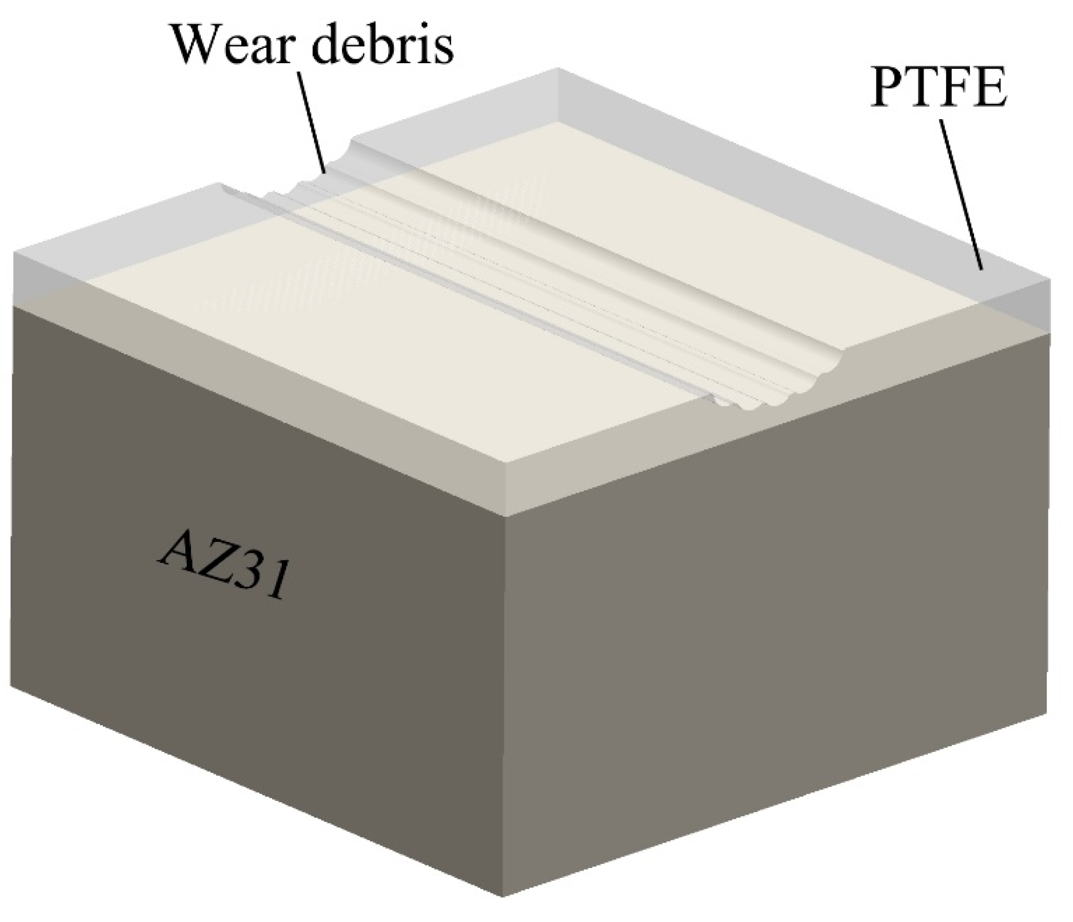
Dry sliding wear tests of AZ31 magnesium alloy before and after electrophoretic deposition of PTFE coating showed that under a 1 N load, the wear volume of AZ31 magnesium alloy decreased by two orders of magnitude after electrophoretic deposition of PTFE coating for 10 and 15 min. The wear mechanism of magnesium alloy involves cutting plowing wear, as well as abrasive wear and oxidative wear. The wear mechanism of electrophoretic deposition of PTFE coating includes the mechanical barrier effect and self-lubricating action of PTFE.
(4)
The optimal deposition time in this experiment is 10 min. The abrasion mechanism of the AZ31 magnesium alloy with a 10 min deposited PTFE coating is similar to that of the coating deposited for 15 min. As the deposition time increases, the abrasion mechanism does not improve significantly, indicating that the lubricating and protective effect of the C-F bonds in PTFE reaches a critical point at 10 min.

Author Contributions

J.Z.: Experiment Completed, Writing—Original Draft, and Investigation, L.C.: Project Administration, Funding Acquisition, and Investigation, C.C.: Project Administration, Funding Acquisition, and Writing—Review, J.L.: Supervision. All authors have read and agree to the published version of the manuscript.

Funding

This work was supported by the National Natural Science Foundation of China (Project No. 52164017) and the Science and Technology Foundation of Guizhou Province (Qianhe Foundation ZK [2023] 250).

Institutional Review Board Statement

Not applicable.

Informed Consent Statement

Not applicable.

Data Availability Statement

Data will be provided upon reasonable request.

Conflicts of Interest

The authors declare no conflict of interest.

References

  1. Jianwei, L.; Youmin, Q.; Junjie, Y.; Sheng, Y.; Yanliang, Y.; Xun, Z.; Lianxi, C.; Fengliang, Y.; Jiangzhou, S.; Zhang, T. Effect of grain refinement induced by wire and arc additive manufacture (WAAM) on the corrosion behaviors of AZ31 magnesium alloy in NaCl solution. J. Magnes. Alloys 2023, 11, 217–229. [Google Scholar] [CrossRef]
  2. Song, J.; She, J.; Chen, D.; Pan, F. Latest research advances on magnesium and magnesium alloys worldwide. J. Magnes. Alloys 2020, 8, 1–41. [Google Scholar] [CrossRef]
  3. Cui, L.-Y.; Gao, S.-D.; Li, P.-P.; Zeng, R.-C.; Zhang, F.; Li, S.-Q.; Han, E.-H. Corrosion resistance of a self-healing micro-arc oxidation/polymethyltrimethoxysilane composite coating on magnesium alloy AZ31. Corros. Sci. 2017, 118, 84–95. [Google Scholar] [CrossRef]
  4. Wu, G.; Zhao, D.; Lin, X.; Liu, J.; Ji, X. Investigation of an environmentally friendly coloring coating for magnesium-lithium alloy micro-arc oxidation. Surf. Interfaces 2020, 20, 100513. [Google Scholar] [CrossRef]
  5. Peng, X.; Liu, W.; Wu, G.; Ji, H.; Ding, W. Plastic deformation and heat treatment of Mg-Li alloys: A review. J. Mater. Sci. Technol. 2022, 99, 193–206. [Google Scholar] [CrossRef]
  6. Tong, L.; Zheng, M.; Xu, S.; Kamado, S.; Du, Y.; Hu, X.; Wu, K.; Gan, W.; Brokmeier, H.; Wang, G. Effect of Mn addition on microstructure, texture and mechanical properties of Mg–Zn–Ca alloy. Mater. Sci. Eng. A 2011, 528, 3741–3747. [Google Scholar] [CrossRef]
  7. Fan, Y.; Wu, G.; Zhai, C. Influence of cerium on the microstructure, mechanical properties and corrosion resistance of magnesium alloy. Mater. Sci. Eng. A 2006, 433, 208–215. [Google Scholar] [CrossRef]
  8. Duan, G.; Yang, L.; Liao, S.; Zhang, C.; Lu, X.; Yang, Y.; Zhang, B.; Wei, Y.; Zhang, T.; Yu, B. Designing for the chemical conversion coating with high corrosion resistance and low electrical contact resistance on AZ91D magnesium alloy. Corros. Sci. 2018, 135, 197–206. [Google Scholar] [CrossRef]
  9. Lin, Z.; Wang, T.; Yu, X.; Sun, X.; Yang, H. Functionalization treatment of micro-arc oxidation coatings on magnesium alloys: A review. J. Alloys Compd. 2021, 879, 160453. [Google Scholar] [CrossRef]
  10. Wang, G.; Song, D.; Qiao, Y.; Cheng, J.; Liu, H.; Jiang, J.; Ma, A.; Ma, X. Developing super-hydrophobic and corrosion-resistant coating on magnesium-lithium alloy via one-step hydrothermal processing. J. Magnes. Alloys 2023, 11, 1422–1439. [Google Scholar] [CrossRef]
  11. Song, W.; Zhao, X.; Jin, Z.; Fan, L.; Ji, X.; Deng, J.; Duan, J. Poly(vinyl alcohol) for multi-functionalized corrosion protection of metals: A review. J. Clean. Prod. 2023, 394, 136390. [Google Scholar] [CrossRef]
  12. Zhou, H.J.; Liu, X.Q.; Su, Q. Development of study on electrophoretic deposition preparing functional thin films. Mater. Rep. 2008, 22, 311–315. [Google Scholar]
  13. An, S.J.; Zhu, Y.; Lee, S.H.; Stoller, M.D.; Emilsson, T.; Park, S.; Velamakanni, A.; An, J.; Ruoff, R.S. Thin film fabrication and simultaneous anodic reduction of deposited graphene oxide platelets by electrophoretic deposition. J. Phys. Chem. Lett. 2010, 1, 1259–1263. [Google Scholar] [CrossRef]
  14. Liu, X.; Qian, T.; Xu, N.; Zhou, J.; Guo, J.; Yan, C. Preparation of on chip, flexible supercapacitor with high performance based on electrophoretic deposition of reduced graphene oxide/polypyrrole composites. Carbon 2015, 92, 348–353. [Google Scholar] [CrossRef]
  15. Kiran, N.U.; Dey, S.; Singh, B.P.; Besra, L. Graphene coating on copper by electrophoretic deposition for corrosion prevention. Coatings 2017, 7, 214. [Google Scholar] [CrossRef]
  16. Yang, Y.; Xiong, X.; Chen, J.; Peng, X.; Chen, D.; Pan, F. Research advances in magnesium and magnesium alloys worldwide in 2020. J. Magnes. Alloys 2021, 9, 705–747. [Google Scholar] [CrossRef]
  17. Yang, W.D.; Huang, J.F.; Cao, L.Y.; Xia, C.K. Hydrothermal electrophoretic deposition technology and its application in preparing functional coatings. Mater. Rev. 2010, 24, 44–48. [Google Scholar]
  18. Zhang, R.; Zhao, J.; Liang, J. A novel multifunctional PTFE/PEO composite coating prepared by one-step method. Surf. Coat. Technol. 2016, 299, 90–95. [Google Scholar] [CrossRef]
  19. Zhao, Q.; Liu, X.; Zhitomirsky, I. Electrophoretic deposition of materials using lithocholic acid as a dispersant. Mater. Lett. 2020, 275, 128129. [Google Scholar] [CrossRef]
  20. Liu, X.; Zhao, Q.; Veldhuis, S.; Zhitomirsky, I. Cholic acid is a versatile coating-forming dispersant for electrophoretic deposition of diamond, graphene, carbon dots and polytetrafluoroethylene. Surf. Coat. Technol. 2020, 384, 125304. [Google Scholar] [CrossRef]
  21. Zhao, Q.; Liu, X.; Veldhuis, S.; Zhitomirsky, I. Sodium deoxycholate as a versatile dispersing and coating-forming agent: A new facet of electrophoretic deposition technology. Colloids Surf. A Physicochem. Eng. Asp. 2020, 588, 124382. [Google Scholar] [CrossRef]
  22. Wang, X.; Wang, B.-B.; Yang, W.; Zhao, Q.; Xu, Z.-M.; Yan, W.-M. Fabrication of stable and versatile superhydrophobic PTFE coating by simple electrodeposition on metal surface. Prog. Org. Coat. 2022, 172, 107090. [Google Scholar] [CrossRef]
  23. Bansal, A.; Singh, J.; Singh, H.; Goyal, D.K. Influence of thickness of hydrophobic polytetrafluoroethylene (PTFE) coatings on cavitation erosion of hydro-machinery steel SS410. Wear 2021, 477, 203886. [Google Scholar] [CrossRef]
  24. Yu, Y.; Chen, L.; Weng, D.; Wang, J.; Chen, C.; Mahmood, A. A promising self-assembly PTFE coating for effective large-scale deicing. Prog. Org. Coat. 2020, 147, 105732. [Google Scholar] [CrossRef]
  25. Farrokhi-Rad, M.; Mohammadalipour, M.; Shahrabi, T. Electrophoretically deposited halloysite nanotubes coating as the adsorbent for the removal of methylene blue from aqueous solution. J. Eur. Ceram. Soc. 2018, 38, 3650–3659. [Google Scholar] [CrossRef]
  26. Besra, L.; Liu, M. A review on fundamentals and applications of electrophoretic deposition (EPD). Prog. Mater. Sci. 2007, 52, 1–61. [Google Scholar]
  27. Wang, S.; Wang, Y.; Zou, Y.; Wu, Y.; Chen, G.; Ouyang, J.; Jia, D.; Zhou, Y. A self-adjusting PTFE/TiO2 hydrophobic double-layer coating for corrosion resistance and electrical insulation. Chem. Eng. J. 2020, 402, 126116. [CrossRef]
  28. Sahu, B.P.; Sarangi, C.K.; Mitra, R. Effect of Zr content on structure property relations of Ni-Zr alloy thin films with mixed nanocrystalline and amorphous structure. Thin Solid Film 2018, 660, 31–45. [Google Scholar] [CrossRef]
  29. Zhou, X.; Shi, W.; Xiang, S. Improving corrosion resistance of Zn-5Al(wt%)alloy by microalloying with samarium. J. Rare Earths 2023, 41, 1636–1644. [Google Scholar] [CrossRef]
  30. Guo, L.; Huang, Q.; Zhang, C.; Wang, J.; Shen, G.; Ban, C.; Guo, L. Study on the formation of Mn-P coatings with significant corrosion resistance on Q235 carbon steels by adjusting the ratio of phosphorus to manganese. Corros. Sci. 2021, 178, 108960. [Google Scholar] [CrossRef]
  31. Song, J.; Zhao, G. A molecular dynamics study on water lubrication of PTFE sliding against copper. Tribol. Int. 2019, 136, 234–239. [Google Scholar] [CrossRef]
  32. Maksoud, A.; Ahmed, H.; Rödel, J. Investigation of the effect of strain rate and temperature on the deformability and microstructure evolution of AZ31 magnesium alloy. Mater. Sci. Eng. A 2009, 504, 40–48. [Google Scholar] [CrossRef]
  33. Jiang, X.; Dai, Y.; Xiang, Q.; Liu, J.; Yang, F.; Zhang, D. Microstructure and wear behavior of inductive nitriding layer in Ti–25Nb–3Zr–2Sn–3Mo alloys. Surf. Coat. Technol. 2021, 427, 127835. [Google Scholar] [CrossRef]
  34. Dhanumalayan, E.; Joshi, G.M. Performance properties and applications of polytetrafluoroethylene (PTFE)—A review. Adv. Compos. Hybrid Mater. 2018, 1, 247–268. [Google Scholar] [CrossRef]
  35. Wu, W.; Zhang, F.; Li, Y.C.; Song, L.; Jiang, D.; Zeng, R.C.; Tjong, S.C.; Chen, D.C. Corrosion resistance of dodecanethiol-modified magnesium hydroxide coating on AZ31 magnesium alloy. Appl. Phys. A 2020, 126, 8. [Google Scholar] [CrossRef]
  36. Ahangari, M.; Johar, M.; Saremi, M. Hydroxyapatite-carboxymethyl cellulose-graphene composite coating development on AZ31 magnesium alloy: Corrosion behavior and mechanical properties. Ceram. Int. 2021, 47, 3529–3539. [Google Scholar] [CrossRef]
  37. Wu, L.; Ding, X.; Zheng, Z.; Ma, Y.; Atrens, A.; Chen, X.; Xie, Z.; Sun, D.; Pan, F. Fabrication and characterization of an actively protective Mg-Al LDHs/Al2O3 composite coating on magnesium alloy AZ31. Appl. Surf. Sci. 2019, 487, 558–568. [Google Scholar] [CrossRef]
  38. Zucchi, F.; Frignani, A.; Grassi, V.; Balbo, A.; Trabanelli, G. Organo-silane coatings for AZ31 magnesium alloy corrosion protection. Mater. Chem. Phys. 2008, 110, 263–268. [Google Scholar] [CrossRef]
  39. Sreekanth, D.; Rameshbabu, N. Development and characterization of MgO/hydroxyapatite composite coating on AZ31 magnesium alloy by plasma electrolytic oxidation coupled with electrophoretic deposition. Mater. Lett. 2012, 68, 439–442. [Google Scholar] [CrossRef]
  40. Asl, S.K.F.; Nemeth, S.; Tan, M. Electrophoretic deposition of hydroxyapatite coatings on AZ31 magnesium substrate for biodegradable implant applications. Prog. Cryst. Growth Charact. Mater. 2014, 60, 74–79. [Google Scholar] [CrossRef]
  41. Jumah, A.J.S. Characterization corrosion behavior of nano alumina coatings on Al12Si fabricated by electrophoretic deposition. Diyala J. Eng. Sci. 2014, 7, 99–114. [Google Scholar] [CrossRef]
  42. Rojaee, R.; Fathi, M.; Raeissi, K. Electrophoretic deposition of nanostructured hydroxyapatite coating on AZ91 magnesium alloy implants with different surface treatments. Appl. Surf. Sci. 2013, 285, 664–673. [Google Scholar] [CrossRef]
  43. Kumar, R.M.; Kuntal, K.K.; Singh, S.; Gupta, P.; Bhushan, B.; Gopinath, P.; Lahiri, D. Electrophoretic deposition of hydroxyapatite coating on Mg–3Zn alloy for orthopaedic application. Surf. Coat. Technol. 2016, 287, 82–92. [Google Scholar] [CrossRef]
Figure 1. (a) SEM, (b) EDS, and (c) the particle size distribution of the PTFE.
Coatings 14 00664 g001
Figure 2. The schematic of the homemade reciprocating friction tester.
Coatings 14 00664 g002
Figure 3. Trend of the impact of additive on the zeta potential.
Coatings 14 00664 g003
Figure 4. Cross-sectional micrographs of PTFE coatings deposited for (a) 5 min, (b) 10 min, and (c) 15 min.
Coatings 14 00664 g004
Figure 5. The cross-sectional micrographs: (a) 200× and (d) 500× magnification of PTFE coating (deposition 5 min), (b) 200× and (e) 500× magnification of PTFE coating (deposition 10 min), (c) 200× and (f) 500× magnification of PTFE coating (deposition 15 min).
Coatings 14 00664 g005
Figure 6. (a) XRD patterns of PTFE coatings and AZ31 Mg alloy, (b) FTIR data for PTFE coating.
Coatings 14 00664 g006
Figure 7. Plot of contact angles of water. Here, the black sign above the bars represents the water contact angle.
Coatings 14 00664 g007
Figure 8. Potential dynamic polarization curves in the 3.5 wt% NaCl solution of various time-deposited coatings.
Coatings 14 00664 g008
Figure 9. Electrochemical impedance spectra of unprotected and protected AZ31 Mg alloy, (a) Nyquist and (b) Impedance Modulus and Bode graphs, (c,d) comparable schematics for circuits. Here, C P E P and R P are the double-layer capacitance of electrolyte and substrate, and charge transfer resistance, respectively.
Coatings 14 00664 g009
Figure 10. The surface micrographs of PTFE-coated Mg AZ31 and EDS of the coating deposited 5 min. (a) deposited for 5 mim; (b) deposited for 10 min; (c) EDS for 5 min (d) deposited for 15 min.
Coatings 14 00664 g010
Figure 11. Curves of the time-friction coefficient for raw samples and different coating qualities under 1 N loads.
Coatings 14 00664 g011
Figure 12. Samples of raw and varied coating quality wear loss under 1 N load. 1# raw sample, 2# deposited 5 min, 3# deposited 10 min, 4# deposited 15 min.
Coatings 14 00664 g012
Figure 13. Under 1 N stress, the 3D morphology and profile of (a) the bare sample, (b) the sample deposited for 5 min, (c) the sample deposited for 10 min, and (d) the sample deposited for 15 min, as well as (e) the profiles of the raw sample and the samples deposited for 5 min, 10 min, and 15 min.
Coatings 14 00664 g013
Figure 14. Wear morphology of raw and PTFE coating under 1 N loads of (a) raw sample, (b) 5 min, (c) 10 min.
Coatings 14 00664 g014
Figure 15. Schematic diagram of abrasion mechanism of AZ31 magnesium alloy after electrophoretic deposition of PTFE coating treatment.
Coatings 14 00664 g015
Table 1. The zeta potential and conductivity of different additives.
SampleP1P2P3
Zeta potential/(mV)5.726720.733.4667
Conductivity/(mS/cm)0.03880.00510.0089
Table 2. Fitting of PTFE coatings with various PTFE deposit times’ potential dynamic polarization curves.
Deposited TimeEcorr/(V)icorr/(µA/m2)βα/(mV·dec−1)βC/(mV·dec−1)Corrosion Rate (mm/a)
0−1.5467.51261920.305
5 min−1.6216.32572850.262
10 min−1.679.62782960.251
15 min−1.635.23653320.246
Table 3. Simulated electrochemical characteristics from the analogous circuit in Figure 5c,d.
SpecimensRf
/(Ω·cm2)
CfnRct/(Ω·cm2)CPE
/(Ω−1cm−2sn)
RP
/(Ω·cm2)
bare 0.9 4.2 × 10−5337.3
5 min5.4562.96 × 10−60.87124.62.27 × 10−5130.056
10 min15.761.25 × 10−60.8215442.65 × 10−51559.76
15 min10.231.16 × 10−60.8335892.37 × 10−53599.23
Disclaimer/Publisher’s Note: The statements, opinions and data contained in all publications are solely those of the individual author(s) and contributor(s) and not of MDPI and/or the editor(s). MDPI and/or the editor(s) disclaim responsibility for any injury to people or property resulting from any ideas, methods, instructions or products referred to in the content.

