Article

The Effect of Self-Healing Microcapsules in Corrosion Testing on Magnesium AZ31 Alloy and Fibre Metal Laminates

by
Monika Ostapiuk
1,*,
Jarosław Bieniaś
1,
Mónica V. Loureiro
2 and
Ana C. Marques
2
1
Department of Materials Engineering, Faculty of Mechanical Engineering, Lublin University of Technology, Nadbystrzycka 36, 20-618 Lublin, Poland
2
Centro de Recursos Naturais e Ambiente (CERENA), Departamento de Engenharia Química (DEQ), Instituto Superior Técnico, Universidade de Lisboa, Av. Rovisco Pais 1, 1049-001 Lisboa, Portugal
*
Author to whom correspondence should be addressed.
Coatings 2024, 14(6), 653; https://doi.org/10.3390/coatings14060653
Submission received: 11 April 2024 / Revised: 30 April 2024 / Accepted: 7 May 2024 / Published: 21 May 2024
(This article belongs to the Section Plasma Coatings, Surfaces & Interfaces)

Abstract

:
Fibre metal laminates (FMLs) are the most interesting composite materials of the past decade. They possess the properties of both polymer composites and metallic alloys. However, there is a problem with corrosion when the outer layers are made of aluminium or magnesium. The electrochemical changes that occur during the corrosion process and the mechanisms associated with the corrosion phenomenon are still being investigated. Recently, self-healing phenomena have emerged as a useful approach to prevent corrosion. However, there is limited research on the combination of FMLs and self-healing layers. Therefore, the main purpose of this article is to evaluate the self-healing ability of a magnesium/PEO layer based on microcapsules in a corrosion environment. It was observed that the corrosion mechanism in magnesium alloys is very complex. However, the use of a barrier layer with PEO treatment and microcapsules yielded positive anti-corrosion results. The FML samples were subjected to a 6-week corrosion test, and the addition of microcapsules to the layers showed positive results. In contrast, the samples without microcapsules exhibited intergranular corrosion. In the future, comprehensive tests using self-healing microcapsules in FMLs could greatly enhance their anti-corrosion properties and improve the integrity of the structure.

1. Introduction

Non-ferrous metal alloys are generally isotropic materials, which are much easier to repair than composite materials. However, polymer composites containing carbon or glass fibres have improved characteristics such as excellent fatigue resistance, high stiffness, and durability. When considering metal materials themselves, problems related to fatigue properties and corrosion may be encountered. Despite the improved characteristics of polymeric composites, their poor ability to be repaired, for example, in aircraft skins, resulted in the development of fibre metal laminates (FML) in the 1980s [1]. These laminates contain alternating metal layers such as aluminium, titanium, or magnesium alloys combined with a polymer composite, such as one containing carbon or glass fibres. In this way, the features of two different structures are combined, which provide new properties, such as improved repairability or increased impact resistance. Moreover, FMLs ensure low moisture absorption, are lightweight, and have high resistance to the propagation of fatigue cracks perpendicular to the fibre direction, due to the fibre bridging mechanism [2,3,4,5,6].
Botelho et al. [4] and Papanicolaou et al. [7] claim that the creation of a permanently bonded contact surface between the metal alloys and the polymer was particularly important in the case of FMLs combined with fibre-reinforced composites. The authors have also reported a significant difference in the mechanical performance between fibre-reinforced composites and FMLs, with the latter showing improved characteristics.
When considering the defects that may occur in FMLs, attention should be paid to the formation of cracks at the interface between the metallic and polymer layers, the occurrence of damage between the polymer layers, and poor adhesion related to the improper preparation of the metal surface. The degradation of laminates, especially those made of aluminium or magnesium combined with layers of polymeric composites based on carbon fibres, may result in the occurrence of galvanic corrosion, particularly in a NaCl electrolyte medium. Ostapiuk et al. [8] proved that FMLs with a surface prepared by anodising aluminium in sulfuric and chromic acid containing carbon fibres are prone to greater and faster corrosion than those containing glass fibres. The formation of a galvanic cell at the junction of two different layers, with distinct corrosion parameters, is responsible for the increased corrosion rate. The surface treatment of the metal layer before bonding is the most important factor in achieving high adhesion. Chemical conversion [9,10], micro-arc oxidation [11,12,13], electrochemical deposition [8,14], and the sol–gel process [15] were applied to improve the corrosion resistance of magnesium alloys.
To address the issue of accelerated corrosion in FMLs and protect the polymer/laminate interface, there are three distinct measures that can be considered: the surface treatment of the metal layer, the introduction of nano/micro fillers (e.g., carbon nanotubes or nanoclay) at the interface of the layers, and the incorporation of a repair agent between the layers (such as micro-/nanocapsules or microparticles). Self-healing materials have been the subject of study for several years and are currently employed in various industries. Among these materials, microcapsules are particularly interesting due to their versatility. The use of self-healing microcapsules allows a material to repair itself in response to external forces or changes in corrosion conditions.
Ostapiuk et al. [14] used microcapsules in research on the interlaminar shear strength (ILSS) of FMLs. Their study focused on observing the effect of structure healing on the interface between the layers of magnesium and a polymer composite containing carbon fibres. Several self-healing agents have been widely proposed. Self-healing microcapsules are advantageous because of their versatility, simplicity, and ease of preparation and use. The use of microcapsules (MCs) for this application was first reported by White et al. [16], who described the storage of a self-healing agent in capsules dispersed in resin. The growth of an interlayer crack ruptures the microcapsules, releasing their core content, a self-healing substance, into the fracture zone. This promotes the self-healing and repair of the layers. Kessler et al. [11] reported on the incorporation of 20 wt% of microcapsules into the contact surface of a carbon fibre–epoxy laminate. They observed an improvement in resistance to interfacial cracking and a 37% self-healing efficiency. However, the original strength was reduced by almost 20%. Ostapiuk et al. [14] reported that the presence of microcapsules does not impair the interlayer failure properties of the FML, especially when adding 1.5 wt% of microcapsules containing isophorone diisocyanate (IPDI). The microcapsules in the FML can also act as reinforcement in the layer. Jin et al. [9] reported that the primary fracture toughness of the interlaminar epoxy–steel joint was improved in the presence of dicyclopentadiene (DCPD)-filled urea-formaldehyde microcapsules, using a double cantilever beam (DCB) fracture specimen. The research by Jin et al. [10] revealed that incorporating polymer hollow and self-healing microcapsules at the interface reduced the fracture toughness of epoxy–steel substrates during the DCB fracture test.
The electrochemical changes that occur during the corrosion process and the mechanisms associated with the corrosion phenomenon are still being investigated, as well as the changes in pH. Electrochemically or pH-responsive materials can then be used to detect and control corrosion.
Microcapsules capable of controlling the release of their internal substance can be designed for use in self-healing applications that involve corrosion. Typically, microcapsules release their contents when they are mechanically broken. However, pH-sensitive microcapsules release their contents in response to corrosion. It is widely understood that mechanical damage to coatings is one of the primary causes of metal corrosion. Additionally, other types of coating defects, such as air bubbles, uneven thickness, penetration, porosity, or edge effects, should also be considered as they can result in the inadequate corrosion protection of the coating.
The microcapsule wall is designed to decompose and release the encapsulated contents in response to changes in pH at the cathodic site of localised corrosion. Various compounds, such as corrosion indicators, inhibitors, self-healing agents, and dyes, can be encapsulated for corrosion applications.
The importance of this work lies on the use of microcapsules in FML systems capable of offering double protection, both through the creation of a barrier and the anti-corrosion effect due to the encapsulation of the corrosion inhibitor. Such a system can provide active protection against both mechanical damage and corrosive factors. In this work, a simple procedure for the synthesis of polyurethane/polyurea (PU/PUa) microcapsules was used. In this article, the self-healing behaviour of FMLs and their coatings were assessed using open circuit potential (OCP), potentiodynamic polarisation, electrochemical impedance spectroscopy (EIS), and a corrosion chamber. The main objective of this work was to assess the self-healing capability of a magnesium/PEO layer utilising microcapsules in a corrosive environment. Furthermore, the study observed the corrosion resistance and self-healing phenomena of fibre metal laminates.

2. Materials and Methods

Isophorone diisocyanate (IPDI), with a purity of 98%, is the isocyanate to be encapsulated. It is commercially known as Desmodur® I and was supplied by Covestro AG (Leverkusen, Germany). The shell precursor, a polyisocyanate called Desmodur® RC, was kindly supplied by CIPADE S.A, Braga, Portugal. The emulsion stabiliser, gum arabic (GA), was purchased from Fisher Chemical (Porto, Salvo, Portugal). The active sources of H—poly(ethyleneimine) (PEI) aqueous solution (Mw 60,000, 50 wt% in H2O) and triethoxy(octyl)silane (n-OTES)—were obtained from Sigma-Aldrich (St. Louis, MO, USA).

2.1. Microcapsule Manufacturing

An oil-in-water (O/W) microemulsion system combined with interfacial polymerization processing was used to manufacture the MCs. The emulsion was produced by vigorously stirring the O and W phases. The O phase consisted of 4.85 wt% of the emulsion and was stirred at a speed of 1200 rpm for 10 min at room temperature (RT) using an Ultra-Turrax (IKA T25 digital ULTRA TURRAX, IKA, Frankfurt, Germany). The O phase of the emulsion was composed of two isocyanates: Desmodur® I, intended to be encapsulated, and Desmodur® RC, a solution of polyisocyanurate of toluene diisocyanate (TDI) in ethyl acetate at 25 wt%. The first isocyanate, the one intended to be encapsulated, comprised 51.2 wt% of the O phase, and Desmodur® RC comprised the remaining 48.8 wt%. The W phase was composed of water and gum arabic (GA), an emulsion stabiliser, present at 4.7 wt%. The emulsion system was subjected to a mild agitation of 500 rpm at 50 °C, and the active H sources, n-OTES (triethoxy(octyl)silane) and an aqueous solution of PEI (polyethylenimine), were added to the synthesis to contribute to the MC shell formation. The synthesis was carried out under the abovementioned conditions for 3 h and 30 min. The maturity of the MCs was evaluated during their fabrication using optical microscopy. Once the necessary maturity was achieved, the MCs were washed with water and centrifuged. The final MCs were dried at atmospheric pressure and room temperature for 96 h and could then be directly added to the sol–gel on magnesium alloy AZ31 and FMLs.

2.2. FML Manufacturing

The FMLs were configured as 2 plies of magnesium and 1 ply of polymer composite, forming a structure that is based on carbon/epoxy resin. The magnesium AZ31 alloy (0.5 mm, Luoyang Shengte Corp., Luoyang, China) served as the metallic layer in the FMLs. The polymer composite was made of unidirectional carbon fibre/epoxy prepreg tape (0.131 mm for one layer, AS7J Hexcel, Stamford, CT, USA).
The FMLs were manufactured in a high-quality autoclave chamber system. During the cure cycle, the pressure used in the autoclave was −0.08 MPa, and a vacuum of −0.02 MPa was applied. The curing temperature was 135 °C, the curing time was 2 h, and the heating/cooling rate was 0.033 K s−1.

2.3. FML Surface Preparation

The plasma electrolytic oxidation (PEO) process was the first stage in preparing the surface of the magnesium AZ31 alloy, which had a thickness of 0.5 mm. The process involved several steps: (i) cleaning/degreasing the surface in an alkaline Na2SiO3 solution; (ii) activating it in 10% HF; (iii) rinsing it in distilled water; and (iv) cleaning the coated samples in distilled water and drying them in controlled ambient-like conditions (Micro Arc, Gliwice, Poland). The aqueous electrolyte used for the PEO process contained 50 g L−1 of sodium metasilicate Na2SiO3 and 40 g L−1 of sodium hydroxide. A constant current of 5 A dm−2 was employed, with a high voltage of up to 400 V and a DC power source used to supply a unipolar pulse of 0.5 ms “on” time and 4.5 ms “off” time. This corresponded to a work cycle frequency of 200 Hz. The PEO treatment process was conducted for 10 min, and the pH was 13.1.

2.4. FML with Microcapsules

The magnesium AZ31 alloy with the PEO layer was coated with a sol–gel. The commercial EC 2333 (3 M Scotch WeldTM, New York, NY, USA) primer, based on resin and inorganic–organic silanes (sol–gel based on toluene, 3-(trimethoxysilyl)propyl glycidyl ether), was used. The primer was applied to the Mg/PEO surface using an atomiser after being mixed with selected amounts of MCs. Afterwards, the samples were dried for 72 h at room temperature in a dryer. A total of 5 wt% of microcapsules was added to the surface of the magnesium alloy AZ31 and FML.

2.5. OCP, Potentiodynamic Polarisation, and EIS Tests

The corrosion resistance of the AZ31 Mg substrate with the sol–gel coating containing the MCs was evaluated using open circuit potential (OCP), polarisation curve, and impedance (EIS) tests. The tests were conducted in a 5 wt% NaCl (aq) solution at room temperature. An Atlas 0531 potentiostat (Atlas-Sollich, Rębiechowo, Poland) with a Frequency Response Analyser (FRA) was used to measure the tests. The samples were directly analysed in the measurement program. The area of the coatings being investigated was limited to 5 cm2, using a flat cell. Three samples were used per test, and the average results are shown on the graphs. The solution was exposed to air and left unstirred.
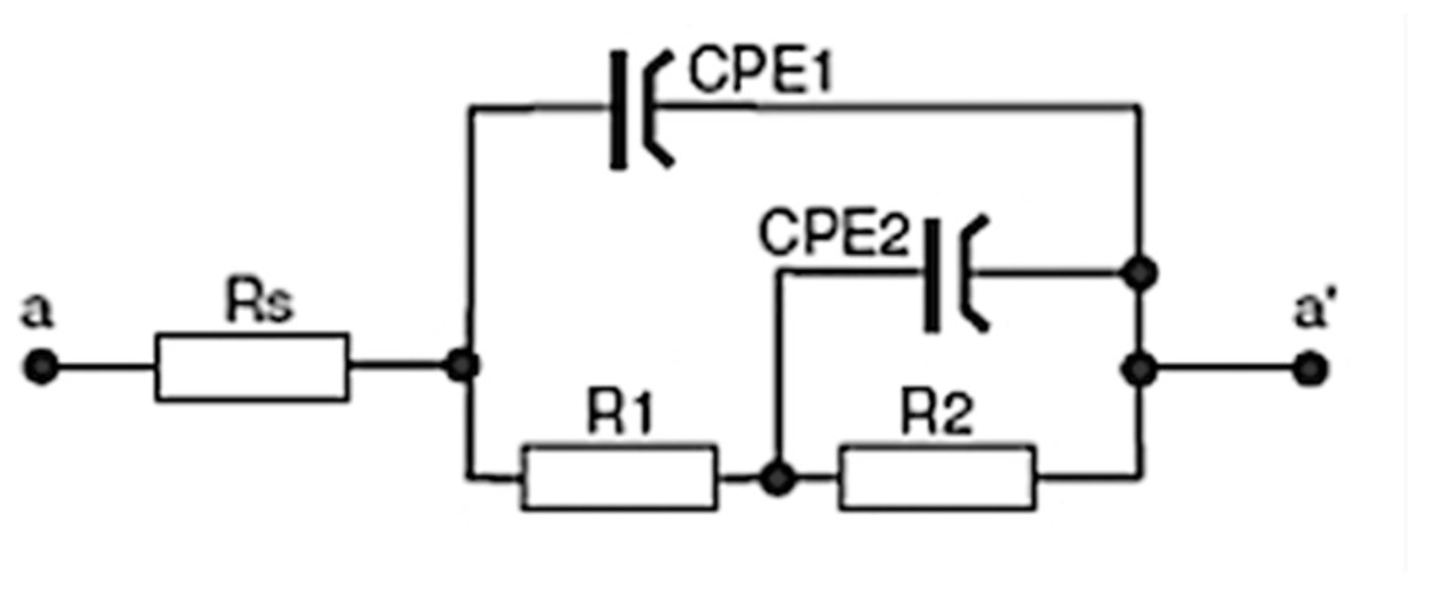
The three-electrode cell consisted of a saturated calomel reference electrode (SCE), a platinum foil electrode, and the test sample (as the working electrode in a horizontal position). A neutral 5% NaCl solution was used for the OCP and potentiodynamic tests at ambient temperature. The NaCl solution used in the corrosion chamber was the same, in order to show the main comparative results. The potentiodynamic current–potential curves were recorded by polarising the specimen from 100 kHz to 0.01 Hz relative to the OCP at a scan rate of 1 mV/s. Next, the EIS tests were carried out after 1 h and 150 h of immersion. The amplitude of the sinusoidal signal was 10 mV versus the open circuit potential, and the frequency span was 100 kHz to 0.01 Hz. The impedance spectra are presented in the form of Bode and Nyquist plots.

2.6. Experiment in Corrosion Chamber

Tests were conducted in a corrosion salt chamber (ASCOTT CC450 xp, Ascott Analytical Equipment Limited, Staffordshire, UK) on magnesium AZ31 and FMLs with and without MCs. A 5 wt% NaCl (aq) electrolyte was used at 37 °C and 95% relative humidity (RH) for six weeks, following EN ISO 9227 [
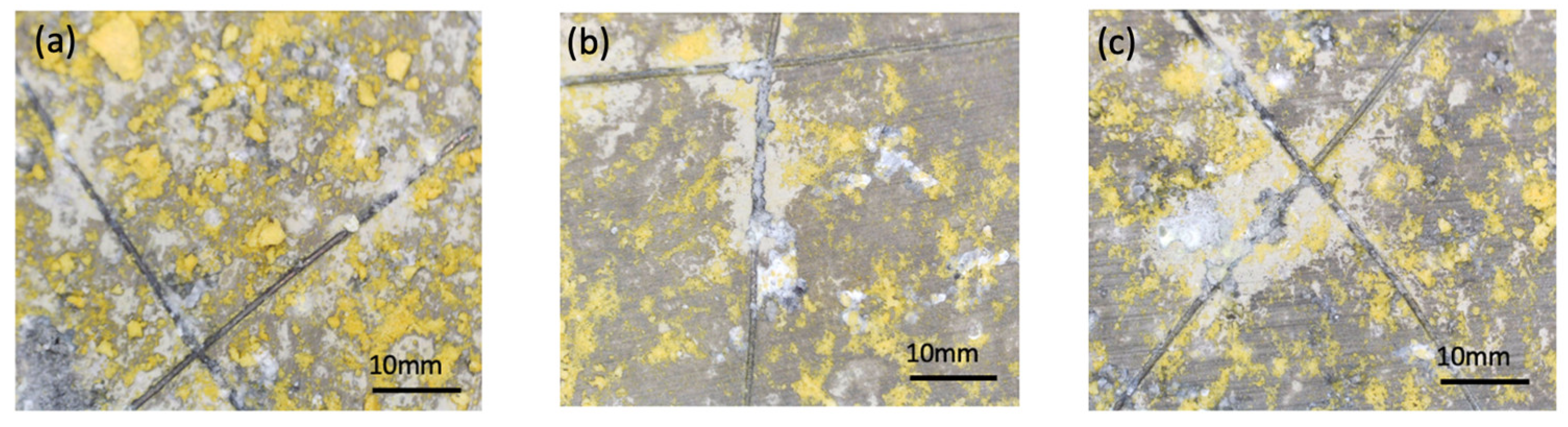
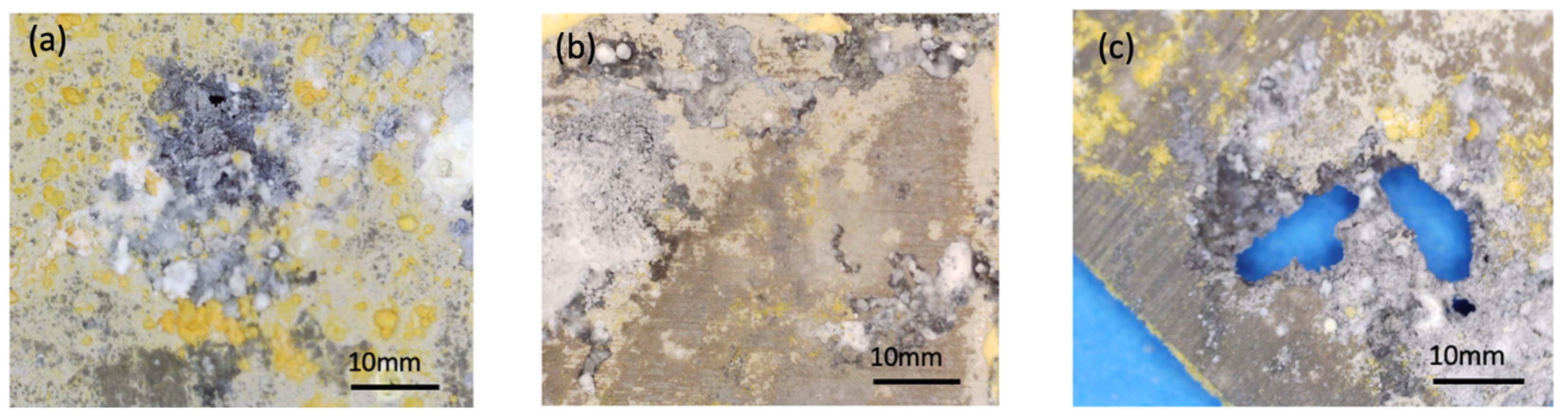
6]. After each week, three samples were collected. An X-shaped graze was made on the coating of the magnesium AZ31 alloy to expose the substrate and assess the healing process of the MCs. The scratch test involved manually creating 2 cm crossed-scratched lines (X-cut) on samples of magnesium alloy AZ31 using a razor blade, with appropriate surface preparation. The scratches had a depth of approximately 50 μm. The scratched samples were then observed using stereoscopic microscopy.
The tests were performed in a 5 wt% NaCl (aq) solution after three different periods of two, four, and six weeks for both the magnesium AZ31 alloy and the FML. The dimensions of the FML samples were 50 mm × 50 mm, and the edges were coated with epoxy to protect against moisture penetration into the composite and prevent undesired premature corrosion at the edges.

2.7. Macro- and Micro-Structure Analysis

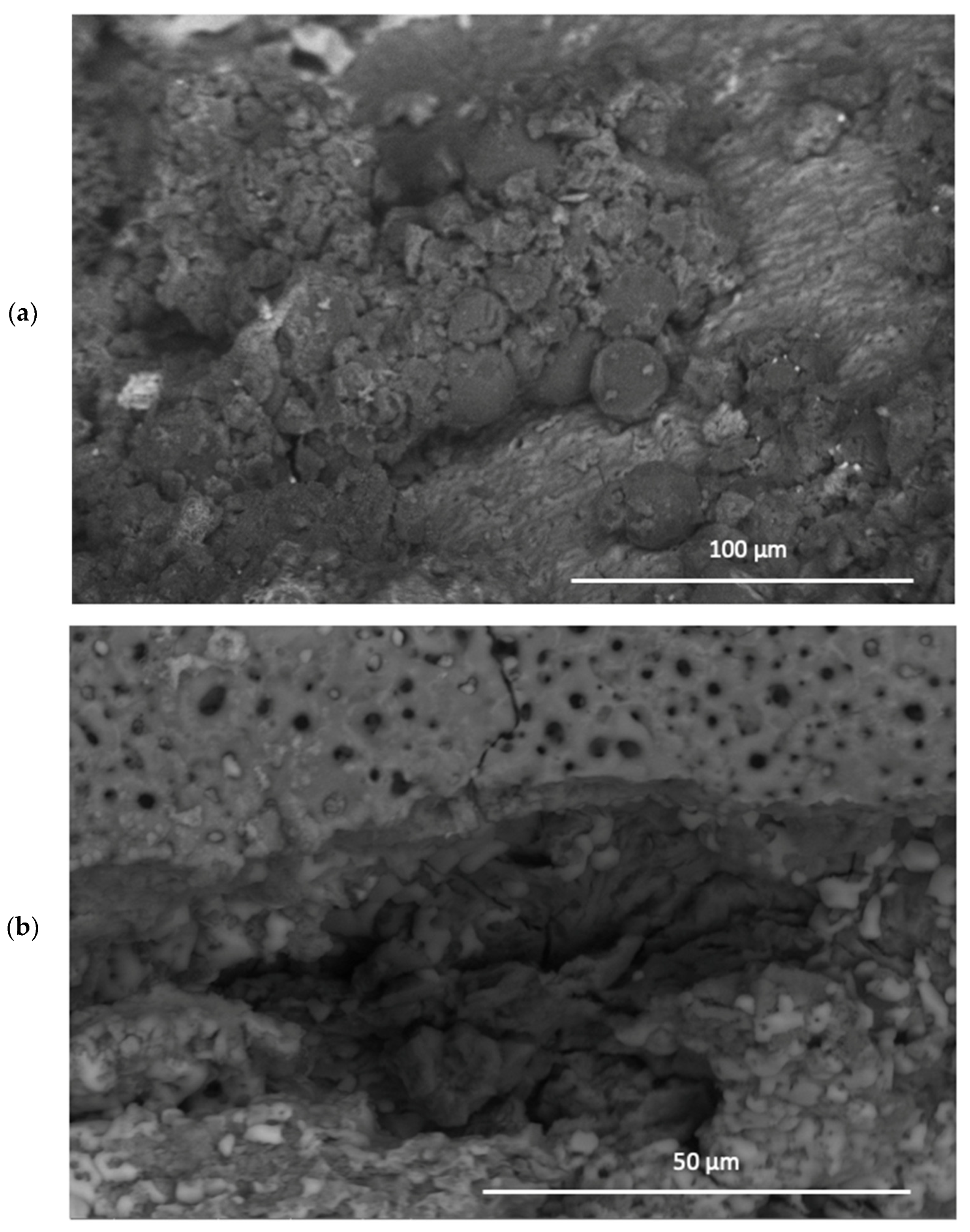
The macro- and micro-structures of the samples before and after the corrosion tests were examined using a stereoscopic microscope (NIKON SMZ 1500, Nikon, Tokyo, Japan) and a scanning electron microscope (SEM, NovaNanoSEM 450, FEI Company Japan Ltd., Tokyo, Japan). The SEM was operated in a low vacuum mode, with a pressure of 100 Pa and voltages of 10 and 15 keV applied.

3. Results

3.1. Microcapsules

Figure 1 shows a scanning electron microscope (SEM) micrograph of a polymer matrix embedded with microcapsules (MCs). The MCs have a spherical shape and a rough shell, which could potentially result in significant interface interactions between the microcapsules and the coating matrix. Further characterization of the MCs can be found in the work by Ostapiuk [15].

3.2. Potentiodynamic Polarisation Study

The electrochemical kinetics of the MC coating was observed using potentiodynamic tests and the Tafel plot in Figure 2.
Polarisation curves were used to evaluate the cathodic and anodic processes on the AZ31 alloy with the MC coating. The polarisation curves were determined using the potentiodynamic method. Corrosion resistance can be estimated from the graph based on the corrosion current density and the icorr value. These values were determined using the Tafel extrapolation method according to ASTM G102 and ASTM G3 standards [2,3]. The selected Tafel plots are presented in Figure 2, and the corrosion parameters are shown in Table 1.
Ostapiuk [15] presented ongoing kinetic changes based on Tafel diagrams for Mg, Mg/PEO, and Mg/PEO sol–gel in 3.5% NaCl. The potential value shifts towards a positive value when there is a coating on the magnesium sample. For all configurations, the samples tend to have passive regions. Polarisation curves were used to evaluate the cathodic and anodic corrosion processes on the AZ31 alloy with the MC coating.
Resistivity (Rpol) indicates excellent insulation (a low conductivity of the coating). If the potential is increased while maintaining a similar current density, the coating is considered to be highly effective—a state that corresponds to passivation.
The corrosion potentials (Ecorr) for AZ31 coated with the MCs were shifted in the positive direction compared to the surface without MCs, indicating anodic protection. The corrosion current density (icorr) is smaller, indicating high protection efficiency, as shown in Table 1. Furthermore, with an increase in potential, the current density is slightly higher, which means that the layer is stable within this range of potential. These parameters demonstrate the effectiveness of the inhibitive coating.
Both the AZ31 magnesium alloy with the MCs (self-healing coating) and the Mg/PEO/sol–gel exhibit a lower passive current density. This indicates that the passive layer formed on the self-healing coating has a higher corrosion resistance compared to a single sol–gel coating.

3.3. Electrochemical Impedance Spectroscopy (EIS)

Figure 3 shows the EIS spectra after 1 h and 150 h, consisting of two capacitive loops in the high- and low-frequency ranges and no inductive loop.
It appears from the Nyquist plot (Figure 3a) that after 1 h, the first loop (from the left for high frequencies) is indicative of the corrosion resistance of the layer, which is related to R1 and C1. R2 is related to the charge transfer resistance of the Mg electrode corrosion reaction. CPE1 represents the constant phase angle element of the Mg electrode/electrolyte double layer, while CPE2 represents the double layer capacitance. R1 represents the impedance of the passivation/adsorption layers. Rs refers to the resistance of the solution, while CPE1 and CPE2 and R2 represent the charge transfer resistance in the interface and the double layer capacitance, respectively. The second loop with a smaller radius (for low frequencies) indicates the electrolyte diffusion process through the layer (R2 and C2 from the model). This process could lead to the degradation of the layer and a reaction with the substrate.
After 150 h (Figure 4b), the loops become less separated, the radius of the left loop increases and the IZI values are higher. This may indicate a reaction of the agent with the MCs, which inhibits the diffusion process and prevents further degradation.
The same equivalent circuit applies to both tests (Figure 4), and after 150 h, the n2 value for CPE2 (admittance Y2) suggests a diffusion process in the layer (Table 2). This could be due to capsule decomposition. Additionally, a notable increase in R2 resistance, accompanied by a simultaneous decrease in Y2 admittance (by three orders of magnitude) and a greater overlap of the two loops in the Nyquist plot, would indicate reactions associated with the release of the polymer compound from the capsules.
Maia F. et al. [12] showed in their article that encapsulation limits the negative interaction of the inhibitor 2-mercaptobenzothiazole (MBT) with the sol–gel matrix, thereby maintaining the barrier properties of the sol–gel layer. This behaviour related to the sol–gel barrier is also observed after 14 days of immersion in a NaCl solution. Additionally, the coating with MBT@PUMC exhibits the highest |Z| in the low frequency region, which is attributed to a lower rate of corrosion-related electrochemical processes on the alloy surface. This demonstrates the active effect of MBT in the system [17].
Figure 5 presents the schematic and physical interpretations of the equivalent circuits for the AZ31 magnesium alloy coated with PEO/MCs + sol–gel after 1 h and 150 h. R1 represents the porosity and deterioration of the PEO and sol–gel layers containing the MCs, while CPE1 is associated with water absorption and coating degradation. The first model includes time constants that correspond to the coating behaviour (R1 and CPE1), while the second model corresponds to the interphase (R2 and CPE2). The parameters CPE2 and R2 are related to the “disbonding” of the coating and the onset of corrosion at the interface, respectively, while Rs represents the electrolyte resistance.
Based on their characteristics, electrical equivalent circuits (EECs) were used for numerical modelling. The values obtained for physical and chemical properties represent the impedance spectra for the polyurethane MCs.
The Nyquist plots obtained from the electrochemical tests of the samples are displayed in Figure 3. According to the Nyquist plots, the total impedance is favourable for concentrations up to 5 wt% of MCs. Other authors have confirmed that increasing the capsule content from 4 wt% leads to better corrosion resistance. However, for a concentration of 7 wt%, a decrease in yield was observed, which is a consequence of problems arising from the agglomeration of the MhCs. This is mainly due to the fact that once the crack is sealed by the polymerisation reaction, IPDI will most likely act as an intact coating.
It was previously shown in Ostapiuk et al. [14] that increasing the concentration of MCs from 0.5 wt% to 1.5 wt% did not result in a reduction in the mechanical properties of the FML samples in the ILSS test. In this article, the authors attempted to increase the MC content to 5 wt% in the FMLs at the interface between the Mg and the CFRP. This concentration was chosen to avoid any potential negative effects on the laminate strength properties. It was proven that 5 wt% was the optimal MC content. This can be explained by the insufficient amount of self-healing agent in the damaged area at low MC concentrations. However, as the authors demonstrate, increasing the concentration of MCs to 30% by weight leads to a reduction in the total impedance value.
Figure 6 shows the surface after EIS after 150 h of immersion in the NaCl solution.
It can be observed that the emergence of pitting corrosion is somewhat inhibited by the MCs that release the IPDI agent. The polymerised IPDI chains are visible, ensuring the sealing of corrosion pits where the MCs were applied.

3.4. Corrosion Chamber

Figure 7 and Figure 8 present the surfaces of samples after testing in a corrosion chamber with 5 wt% NaCl. Figure 7 shows samples without MCs, while Figure 8 shows samples containing 5 wt% MCs.
Figure 7d shows the structure of Mg itself with the PEO layer. It is evident that intergranular corrosion, specifically pitting corrosion, had already occurred within the first 2 weeks. This can be observed on the edges of the sample. Subsequent weeks demonstrate the complete perforation of Mg, leading to a significant loss of material in the structure by the sixth week.
However, Figure 8 shows a scratched surface with MCs.
The corrosion reaction in the scratched coating is not visible, and the scratches are clean and free of corrosion products even after 2 weeks. It is evident that the coating regenerates itself and provides better resistance even when scratched. However, after 4 and 6 weeks, localised areas in the scratches causing pitting corrosion may be observed.
In the tests, the MCs act as a protective barrier against corrosion, as corrosion is significantly delayed in the areas containing MCs. However, for FMLs (Figure 9), which contain a layer of carbon fibres, corrosion is significantly accelerated. By the second week, corrosion pits can already be observed in the areas where MCs are absent. Furthermore, perforation throughout the composite is visible by the 6th week. This indicates the creation of a galvanic cell in which the MCs are unfortunately no longer sufficient to prevent corrosion.

4. Discussion

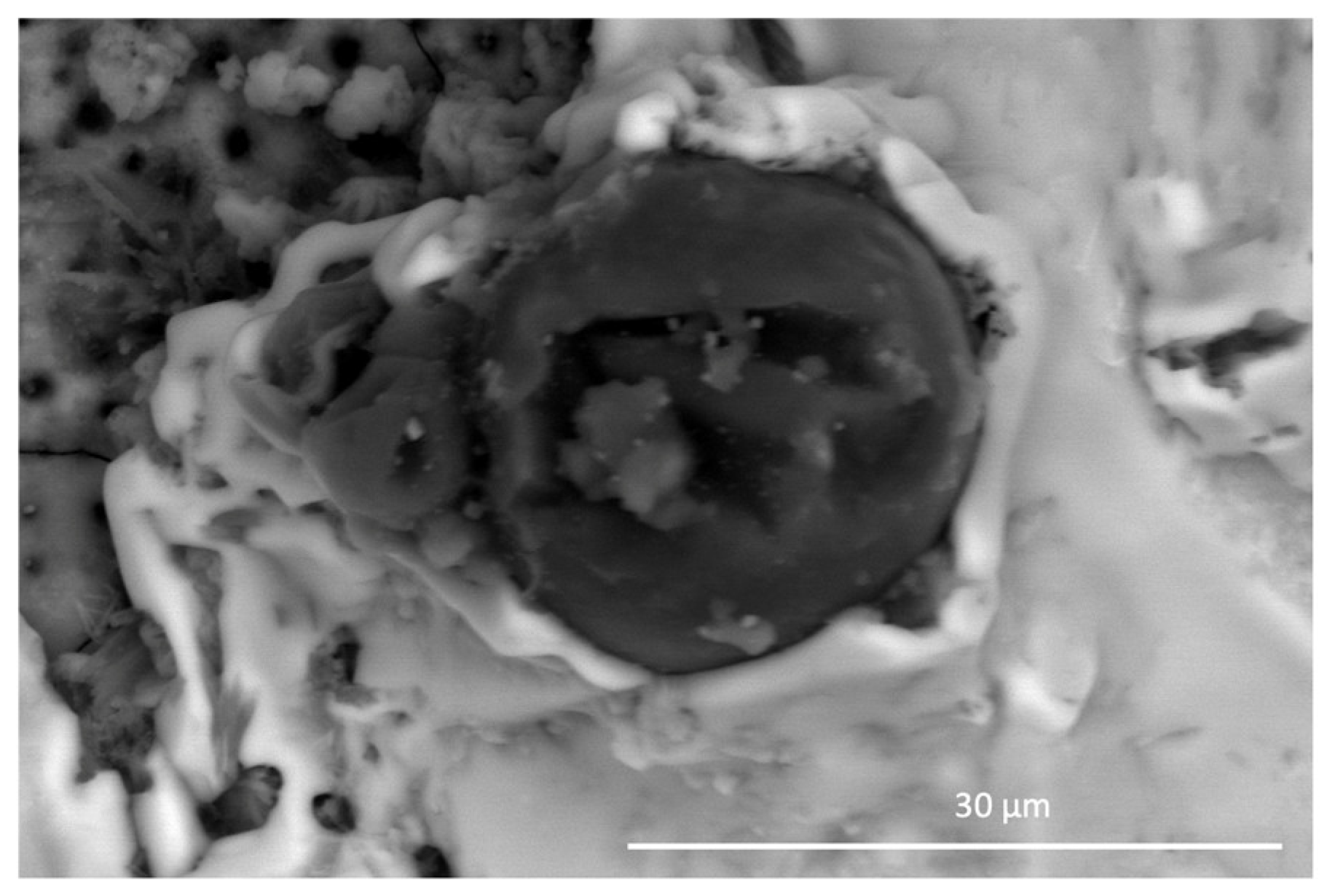
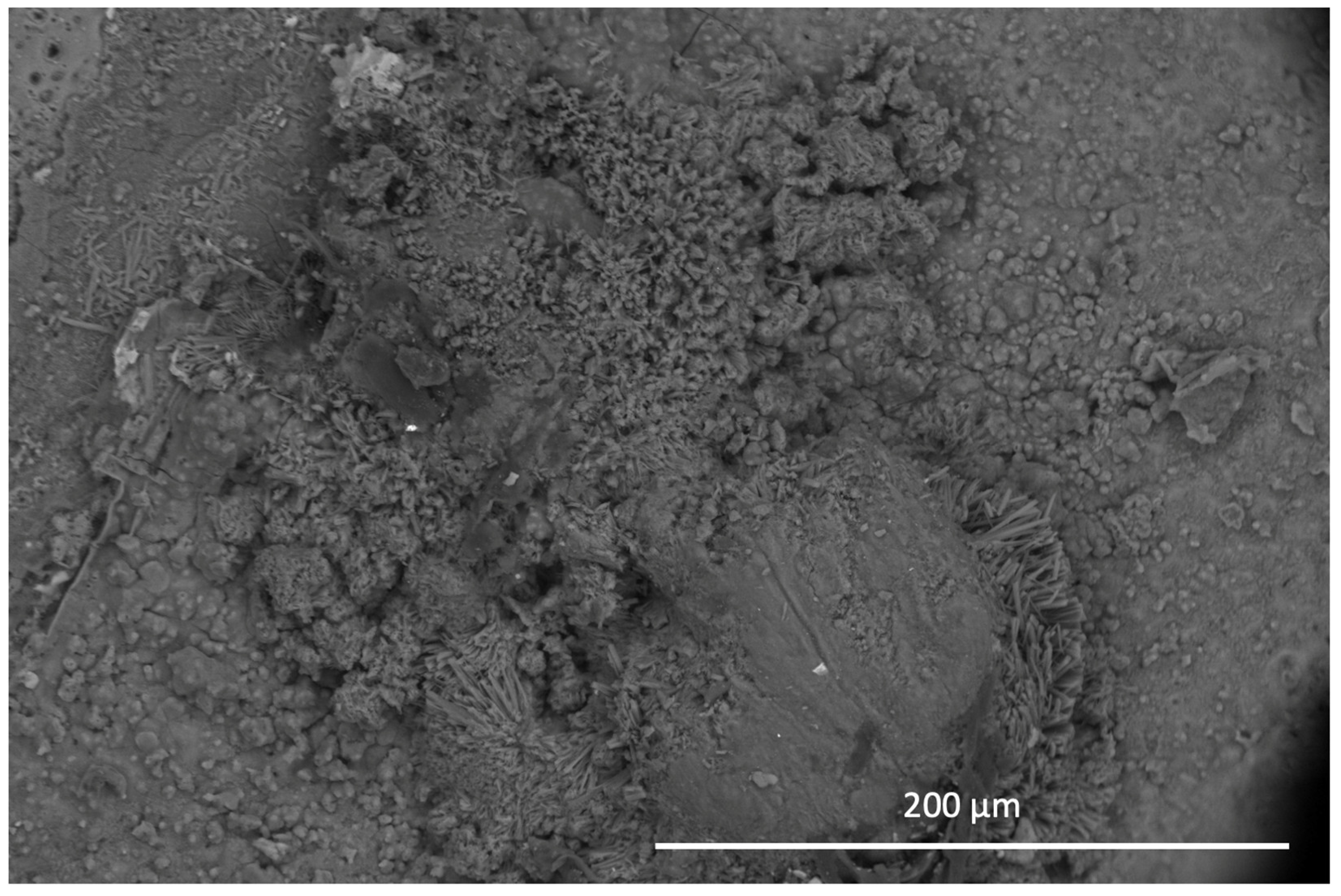
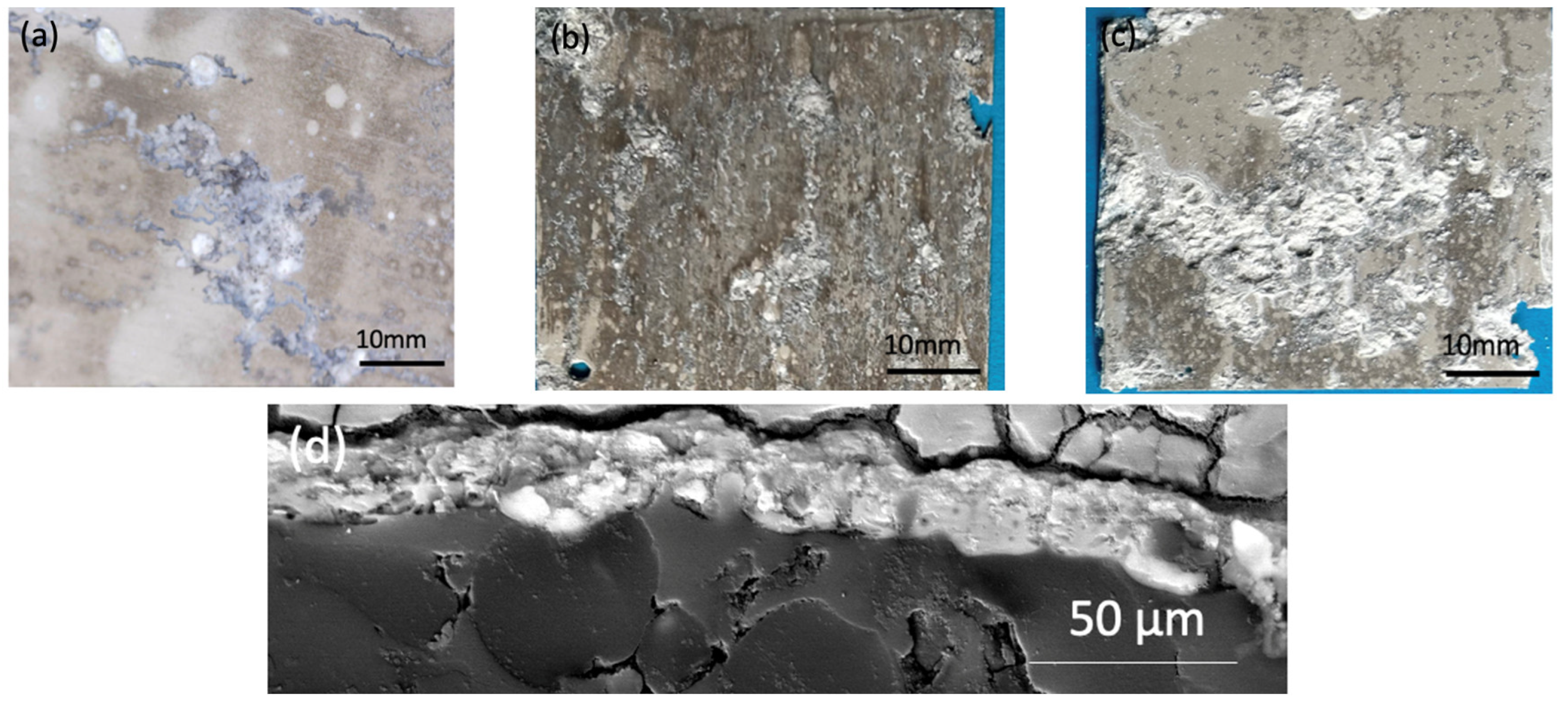
All samples were exposed to a 5 wt% NaCl environment in a corrosion chamber for 6 weeks. The MCs show a uniform distribution throughout the coating in the samples to which they were added. On the other hand, the samples without MCs reveal the phenomenon of intergranular corrosion. The SEM micrographs of the scratched coating and the self-healing coating are displayed in Figure 10. The IPDI polymerised and formed a solid layer. Indeed, the IPDI was released from the MCs and automatically covered the scratch on the coating surface. The MCs are shown to provide excellent corrosion protection under the abovementiones conditions. After 48 h of exposure to the NaCl solution, no signs of corrosion were observed.
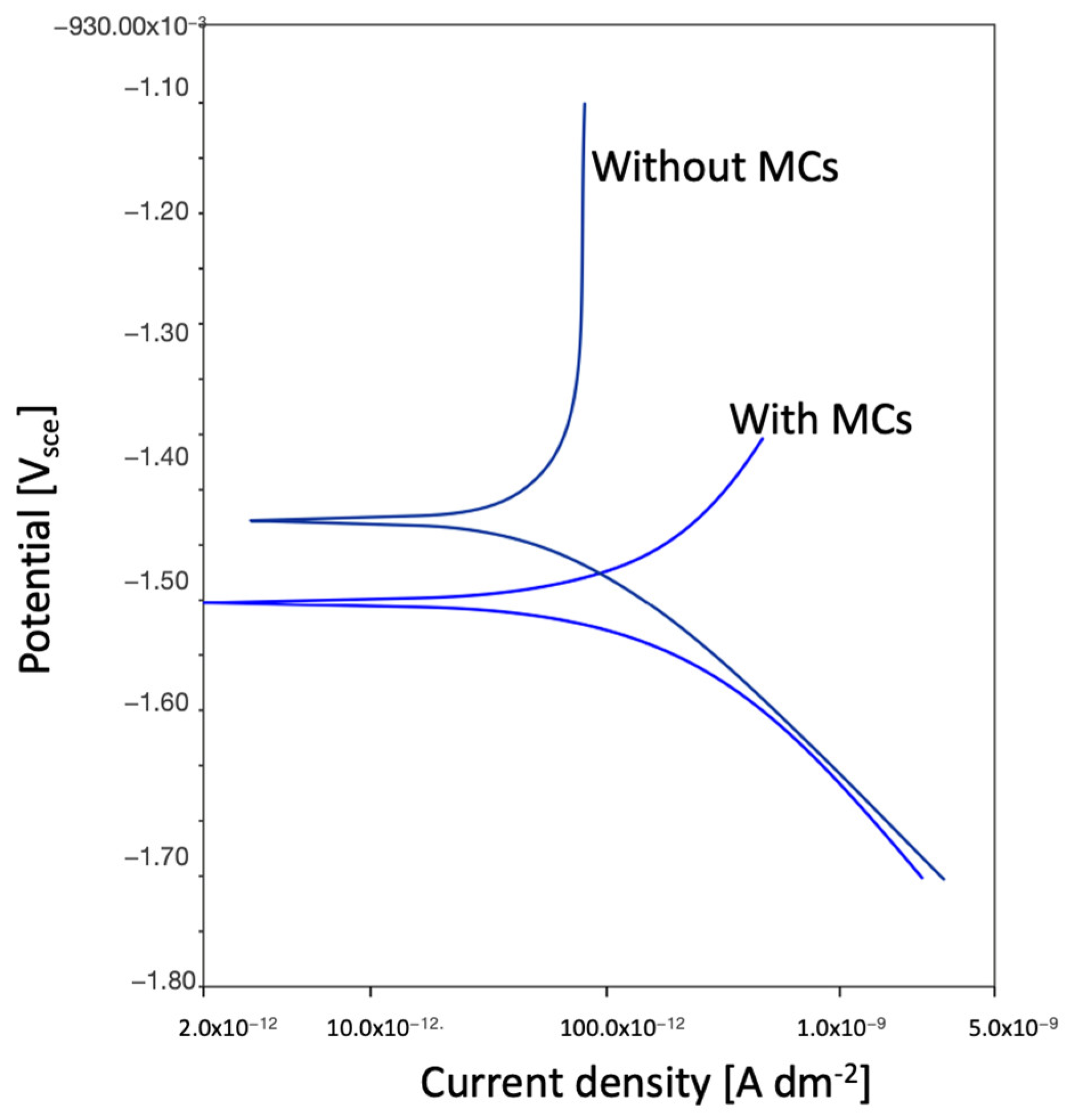
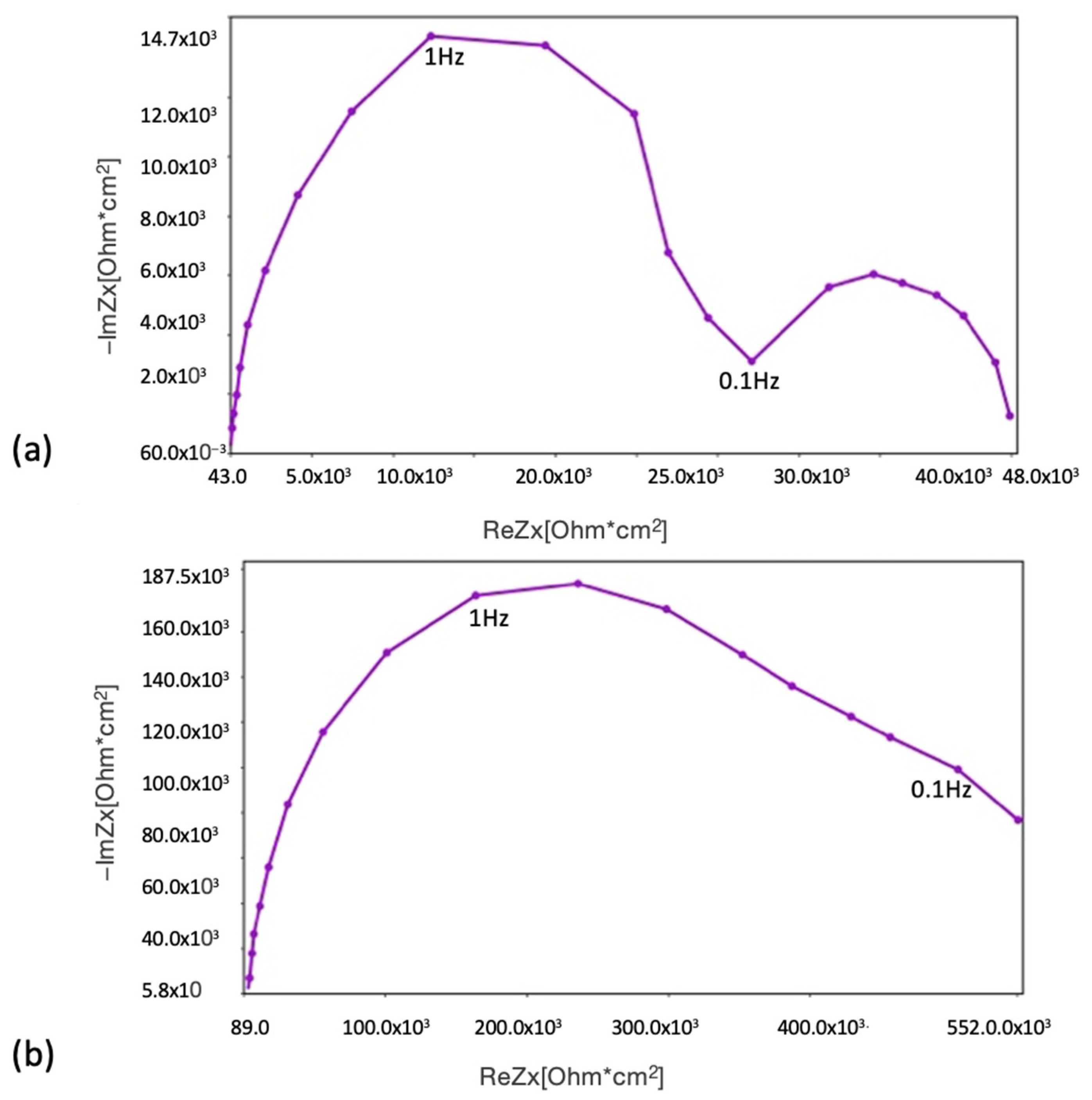
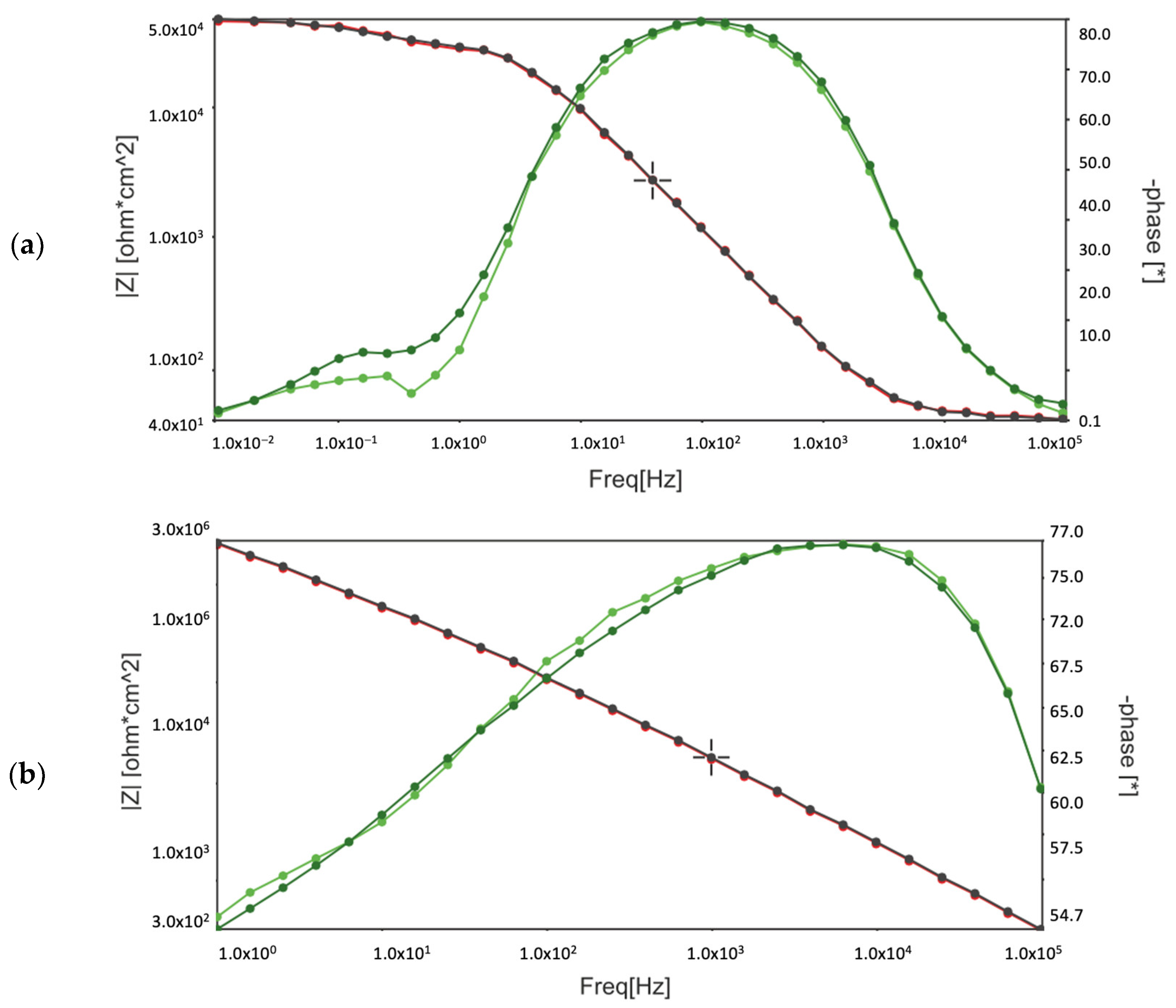
Comparing the test results obtained from EIS, potentiodynamic tests, and the corrosion chamber, it can be seen that the MCs layer obtained on AZ31 fulfils its role. It is noticeable that without MCs, corrosion clearly progresses after 1 h. However, self-healing mechanisms occur in the polymer layer with MCs. In these tests, the same pattern of corrosion phenomena, especially pitting corrosion, was observed. However, the polymer layer with MCs clearly affects the protection of the magnesium layer against subsequent corrosion phenomena. When pitting corrosion occurs, MCs release a self-healing agent, thereby reducing the effects of corrosion.
An issue that needs to be considered is the solubility of the corrosion inhibitors. When formulating the coating, it is important to select an inhibitor that can offer effective corrosion protection. The “solubility window” should be taken into account, as low solubility can lead to a reduction or absence of ions that inhibit corrosion. On the other hand, using too many inhibitors can cause them to wash out and diffuse onto the metal surface. If solubility is higher, the inhibitors may leach out of the coating and be lost, resulting in limited protection for the substrate over a certain period of time.
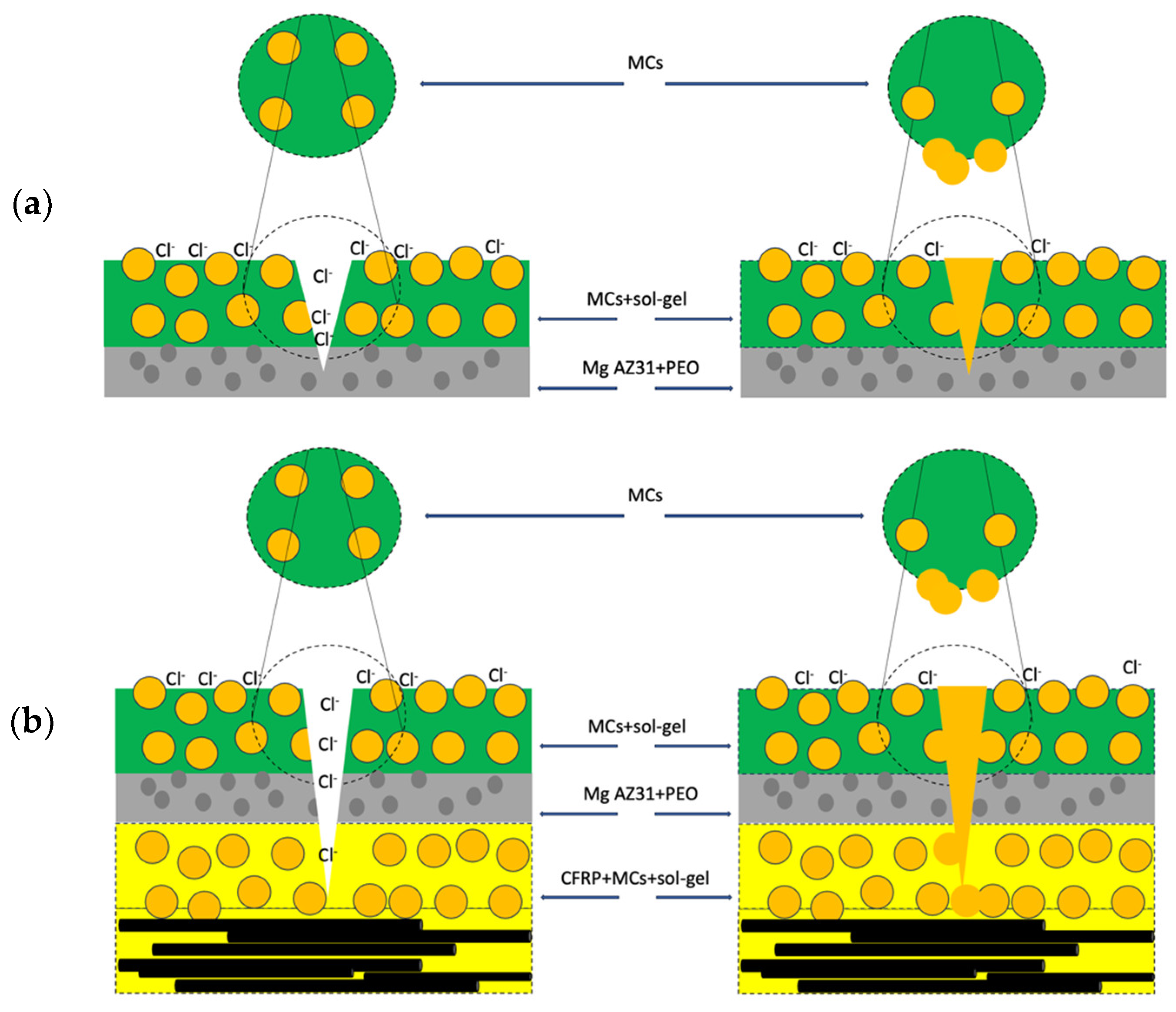
A diagram illustrating the inhibition mechanism provided by the MCs loaded with IPDI on the Mg/PEO and in the FML is presented in Figure 11. This diagram reveals the hydrophobic-based corrosion mechanism during the adsorption process.

5. Conclusions

This article describes the mechanism of corrosion phenomena on magnesium/PEO layer and fibre metal laminates, and the tests conducted using self-healing microcapsules. It was observed that the corrosion mechanism in magnesium alloy is very complex. The barrier layer with PEO treatment and microcapsules yielded positive results in terms of anti-corrosion properties. The FML samples were exposed to the corrosion chamber for six weeks and showed positive results when microcapsules were added to the layers. The microcapsules were uniformly distributed throughout the coating in the samples where they were added. Conversely, the samples without microcapsules exhibited intergranular corrosion. For future applications, comprehensive testing could be conducted by incorporating self-healing microcapsules in FMLs. Using a self-healing layer could help improve the structural integrity and mitigate corrosion phenomena.

Author Contributions

Conceptualisation, M.O. and A.C.M.; methodology, M.O.; software, M.O.; validation, M.O.; formal analysis, M.O.; investigation, M.O. and M.V.L.; resources, M.O.; data curation, M.O. writing—original draft preparation, M.O. and M.V.L. writing—review and editing, M.O., A.C.M.; visualisation, M.O. and J.B.; supervision, J.B.; project administration, M.O.; funding acquisition, M.O. and A.C.M. All authors have read and agreed to the published version of the manuscript.

Funding

The research was conducted thanks to funding from the Polish National Agency for Academic Exchange, known as the Bekker program [No. PPN/BEK/2018/1/00213]. The authors gratefully acknowledge Fundacão para a Ciência e a Tecnologia (FCT) through the support of CERENA (Strategic Project FCT-UIDB/04028/2020). The work was developed under COST Action CA18120—“CERTBOND-Reliable roadmap for certification of bonded primary structures”.

Institutional Review Board Statement

Not applicable.

Informed Consent Statement

Not applicable.

Data Availability Statement

Data are contained within the article.

Conflicts of Interest

The authors declare no conflicts of interest.

References

  1. Anderson, T.L. Fracture Mechanics: Fundamentals and Applications; Taylor & Francis Group, LLC: Abingdon, UK, 2005. [Google Scholar]
  2. ASTM G102-89(1999); Standard Practice for Calculation of Corrosion Rates and Related Information from Electrochemical Measurements. ASTM International: West Conshohocken, PA, USA, 1999.
  3. ASTM G3-14(2019); Standard Practice for Conventions Applicable to Electrochemical Measurements in Corrosion Testing. ASTM International: West Conshohocken, PA, USA, 2019.
  4. Botelho, E.C.; Rezende, M.C.; Pardini, L.C. Hygrothermal effects evaluation using the iosipescu shear test for Glare laminates. J. Braz. Soc. Mech. Sci. Eng. 2008, 30, 213–220. [Google Scholar] [CrossRef]
  5. Chen, W.W.; Wang, Z.X.; Sun, L.; Lu, S. Research of growth mechanism of ceramic coatings fabricated by micro-arc oxidation on magnesium alloys at high current mode. J. Magnes. Alloys 2015, 3, 253–257. [Google Scholar] [CrossRef]
  6. EN ISO 9227:2022; Corrosion Tests in Artificial Atmospheres. Salt Spray Tests. ISO: Geneva, Switzerland, 2022.
  7. Papanicolaou, G.C.; Bakos, D.J.; Kosmidou, T.V. Effect of the interface stiffness and skin-core adhesion efficiency on the interfacial stress distribution of sandwich structures. Comp. Part A 2007, 38, 1099–1106. [Google Scholar] [CrossRef]
  8. Ostapiuk, M.; Loureiro, M.V.; Bieniaś, J.; Marques, A.C. Interlaminar shear strength study of Mg and carbon fibre-based hybrid laminates with self-healing microcapsules. Comp. Struct. 2021, 255, 113042. [Google Scholar] [CrossRef]
  9. Jin, H.; Miller, G.M.; Pety, S.J.; Griffin, A.S.; Stradley, D.S.; Roach, D.; Sottos, N.R.; White, S.R. Fracture behavior of a self-healing, toughened epoxy adhesive. Int. J. Adhes. Adhes. 2013, 44, 157–165. [Google Scholar] [CrossRef]
  10. Jin, H.; Miller, G.M.; Sottos, N.R.; White, S.R. Fracture and fatigue response of a self- healing epoxy adhesive. Polymer 2011, 52, 1628–1634. [Google Scholar] [CrossRef]
  11. Kessler, M.R.; Sottos, N.R.; White, S.R. Self-healing structural composite materials. Compos. A Appl. Sci. Manuf. 2003, 34, 743–753. [Google Scholar] [CrossRef]
  12. Maia, F.; Yasakau, K.A.; Carneiro, J.; Kallip, S.; Tedim, J.; Henriques, T.; Cabral, A.; Venâncio, J.; Zheludkevich, M.L.; Ferreira, M.G.S. Corrosion protection of AA2024 by sol–gel coatings modified with MBT-loaded polyurea microcapsules. Chem. Eng. J. 2016, 283, 1108. [Google Scholar] [CrossRef]
  13. Meng, E.C.; Guan, S.K.; Wang, H.X.; Wang, L.G.; Zhu, S.J.; Hu, J.H.; Ren, C.X.; Gao, J.H.; Feng, Y.S. Effect of electrodeposition modes on surface characteristics and corrosion properties of fluorine-doped hydroxyapatite coatings on Mg–Zn–Ca alloy. Appl. Surf. Sci. 2011, 257, 4811–4816. [Google Scholar] [CrossRef]
  14. Ostapiuk, M. Corrosion resistance of PEO and primer coatings on magnesium alloy. J. Asian Ceram. Soc. 2021, 9, 40–52. [Google Scholar] [CrossRef]
  15. Ostapiuk, M.; Bieniaś, J. Corrosion Resistance in NaCl Environment of Fibre Metal Laminates based on Aluminum and Titanium Alloys with Carbon and Glass Fibres. Adv. Eng. Mat. 2021, 23, 2001030. [Google Scholar] [CrossRef]
  16. White, S.R.; Sottos, N.R.; Geubelle, P.H.; Moore, J.S.; Kessler, M.R.; Sriram, S.R.; Brown, E.N.; Viswanathan, S. Autonomic healing of polymer composites. Nature 2001, 409, 794–797. [Google Scholar] [CrossRef] [PubMed]
  17. Zhang, X.; Zhang, Y.; Ma, Q.Y.; Dai, Y.; Hu, F.P.; Wei, G.B.; Xu, T.C.; Zeng, Q.W.; Wang, S.Z.; Xie, W.D. Effect of surface treatment on the corrosion properties of magnesium-based fibre metal laminate. Appl. Surf. Sci. 2017, 396, 1264–1272. [Google Scholar] [CrossRef]
Figure 1. Microstructure of MCs.
Coatings 14 00653 g001
Figure 2. Potentiodynamic polarisation curves of a polymer coating with 5 wt% MCs and without MCs.
Coatings 14 00653 g002
Figure 3. Nyquist plot after (a) 1 h; and (b) 150 h of MCs.
Coatings 14 00653 g003
Figure 4. The Bode plots with MCs after (a) 1 h; and (b)150 h.
Coatings 14 00653 g004
Figure 5. Electric equivalent circuits used for EIS fitting for AZ31/PEO/sol–gel/MCs.
Coatings 14 00653 g005
Figure 6. SEM micrograph of Mg/PEO/sol–gel/MC surface after 150 h EIS test.
Coatings 14 00653 g006
Figure 7. Photographs of Mg/PEO surface layer after (a) 2 weeks; (b) 4 weeks; (c) 6 weeks, with visible pitting; and (d) intergranular corrosion.
Coatings 14 00653 g007
Figure 8. Cut surface of Mg with MCs after (a) 2 weeks, (b) 4 weeks; and (c) 6 weeks, with visible self-healing areas and pitting corrosion.
Coatings 14 00653 g008
Figure 9. Surface of FML after (a) 2 weeks, (b) 4 weeks; and (c) 6 weeks, including MCs and pitting corrosion.
Coatings 14 00653 g009
Figure 10. Surface of Mg/PEO with MCs: (a) ruptured MCs and released IPDI; (b) pitting corrosion.
Coatings 14 00653 g010
Figure 11. Simplified diagram of corrosion inhibition mechanism by MCs loaded in (a) Mg/PEO; and (b) FML.
Coatings 14 00653 g011
Table 1. Corrosion parameters of polymer coating AZ31 in 5% NaCl.
MC Concentration
[% wt]
OCP
[V SCE]
Corrosion Potential
Ecorr
[V SCE]
Corrosion Current Density icorr
[A cm−2]
βa
mV dec−1
βc
mV dec−1
Rpol
[kΩ cm2]
Protection Efficiency
[%]
0−1.37 ± 0.021.40 ± 0.02257.83 × 10−9 ± 13.9819.59 × 109 ± 1.99136.34 ± 11.78373.71 ± 18.99-
5−1.43 ± 0.05−1.45 ± 0.04289.85 × 10−12 ± 9.08524.322 × 10−3 ± 23.22273.71 × 10−3 ± 14.56269.40 × 103 ± 10.92~75
Table 2. The mean value of the EIS test.
Time (h)Rs (Ωcm2)Y1 (S/cm2)n1R1 (kΩcm2)Y2 (S/cm2)n2R2 (kΩcm2)
143 ± 1(1.97 ± 0.09) × 10−60.934 ± 0.0732.81 ± 1.25(118 ± 3.6) × 10−61 ± 0.1712.93 ± 2.43
150107 ± 15(15.6 ± 1.3) × 10−90.916 ± 0.0131.78 ± 0.05(117 ± 5.8) × 10−90.527 ± 0.017(31.5 ± 1.2) × 109
Disclaimer/Publisher’s Note: The statements, opinions and data contained in all publications are solely those of the individual author(s) and contributor(s) and not of MDPI and/or the editor(s). MDPI and/or the editor(s) disclaim responsibility for any injury to people or property resulting from any ideas, methods, instructions or products referred to in the content.

