Article

Effects of ZrW2O8 Content on the Microstructures and Properties of Composite Coatings Produced by Laser Cladding

1
State Key Laboratory of Advanced Processing and Recycling of Non-Ferrous Metals, Lanzhou University of Technology, Lanzhou 730050, China
2
School of Materials Science and Engineering, Lanzhou University of Technology, Lanzhou 730050, China
*
Author to whom correspondence should be addressed.
Coatings 2024, 14(5), 649; https://doi.org/10.3390/coatings14050649
Submission received: 28 April 2024 / Revised: 16 May 2024 / Accepted: 17 May 2024 / Published: 20 May 2024

Abstract

:
Addressing the issue of cracking in laser-cladding Ni-based composite coatings with WC particles, this study explored an approach to fabricating a crack-free coating by incorporating ZrW2O8 powder. The influence of varying ZrW2O8 contents on the crack susceptibility, microstructure, microhardness, wear resistance, and corrosion resistance of Ni60/WC composite coatings was systematically examined. The findings indicate that the ZrW2O8 content significantly impacts the microstructure and functional properties of the coating. Furthermore, it is suggested that the main contributors to preventing crack formation and diffusion are believed to be the pressure interaction caused by the negative expansion effect of ZrW2O8, as well as the in situ phase transition and diffusion toughening of ZrO2 during its decomposition process. The feasibility of achieving crack selfhealing through the addition of specific amounts of ZrW2O8 powder has been conclusively demonstrated.

1. Introduction

The stainless steel ball valve is a crucial component in industrial pipeline transport systems. Its service conditions are often complex and variable, and the contact surface is susceptible to abrasion and corrosion by various fluid media, which can result in the ball valve’s overall failure. The use of laser cladding technology to prepare stainless steel surfaces and apply metal matrix composite (MMC) coatings has been shown to be an effective method for improving surface performance and extending service life [1,2,3,4].
GUO [5] and co-authors showed that the microhardness and wear resistance of nickel-based composite coatings with added WC ceramic particles via laser cladding were greatly enhanced. However, when the WC content exceeds a certain degree, cracks appear in the WC-Ni coating that are difficult to eliminate by preheating measures. Debapriya Patra Karmakar et al. [6] found that the performance of Stellite6/WC composite cladding coatings surpassed that of single Stellite6 coatings. However, microcracks were observed in the WC composite coatings. Chen et al. [7] also reported similar findings. The study compared the effects of incorporating micron-sized and nano-sized WC particles on the properties of nickel-based composite cladding coatings. The results showed that nano-WC particle coatings have significant advantages in terms of strong toughness and corrosion resistance, while wear cracks were observed in the coating with micron-sized WC particles. Li [8] and others prepared WC/Ni60 composite coatings with a 5%–35% WC mass fraction by laser cladding and found that the microhardness and corrosion resistance of the coatings improved significantly with the increase in WC content. However, when the WC content is high, the coating will show visible cracks and be more likely to fall off the matrix.
While laser cladding can significantly improve the surface properties of WC/Ni composite coatings, residual stresses resulting from thermal expansion mismatch between the matrix and ceramic particles can cause cracks or even peeling from the matrix [9,10,11,12,13,14]. To regulate the expansion coefficient in composite coatings, some scholars have introduced the negative thermal expansion material ZrW2O8. This helps control expansion behavior, reduce residual stresses, and achieve zero cracking of the laser fusion cladding layer [15,16,17,18]. Islam et al. [19] showed that the inclusion of 1% ZrW2O8 nanoparticles can decrease the degree of thermal expansion mismatch in carbon fiber-reinforced polymer composites during polymerization, thereby reducing thermal expansion mismatch in these composites. Wu [20] and co-authors successfully developed homogeneous low thermal expansion Al/ZrW2O8 composites by adding 50% ZrW2O8 to a pure aluminum matrix using the squeeze casting method. They controlled the phase transition in the composites with the help of heat treatment. Qi et al. [21]. utilized laser cladding technology to fabricate a ZrW2O8/NiCrBSi composite coating on a 42CrMo matrix, exhibiting an absence of noticeable cracks. In summary, there are few reports on the use of negative thermal expansion material ZrW2O8 to control cracks in laser cladding coatings. Moreover, studies on the regulation of cracking tendencies in WC/Ni60 laser cladding composite coatings using ZrW2O8 have not yet been reported.
In this study, different contents of ZrW2O8 were introduced into WC/Ni60 metal matrix composites to form laser cladding coatings. The investigation explored the crack sensitivity of the composite coatings with the incorporation of negative thermal expansion material and examined the effects on microstructure, hardness, wear resistance, and corrosion resistance. The study elucidates the mechanism by which ZrW2O8 eliminates microcracks in the WC/Ni60 metal matrix composite cladding coatings and provides a new approach for achieving metallurgical defect self-healing in the laser cladding composite coating preparation process.

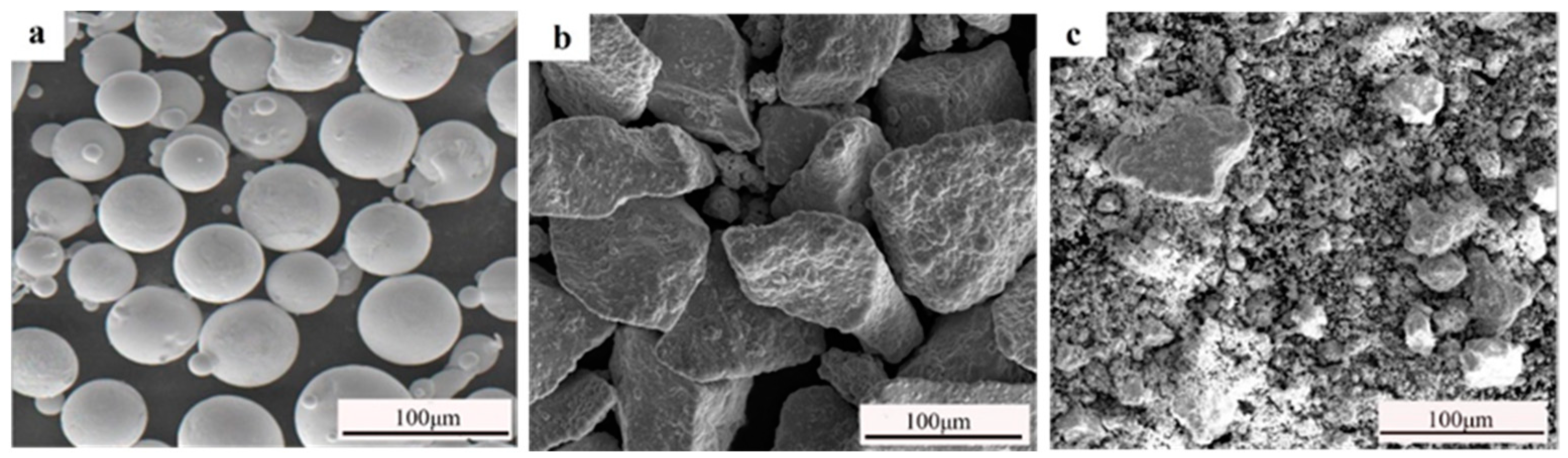
2. Materials and Methods

In this experiment, the substrate was stainless steel 304 with dimensions of 100 mm × 65 mm × 10 mm. The chemical composition of 304 stainless steel is shown in Table 1. The clad materials used were composed of a mixture of Ni60 with particle sizes of 10–50 μm and nickel-wrapped WC particles sized 20–120 μm. Table 2 lists the chemical composition of the Ni60 powder. ZrW2O8 powder sized 0.5–3 μm and Ni60/WC powder were mixed under different weight fractions using a QM-2SP20-CL (Nanjing University Instrument Factory, Nanjing, China) planetary ball mill (ZrO2 ceramic ball, ball-to-material ratio 4:1, a rotating speed of 120 r/min, and a mixing time of 3 h). Figure 1 shows the scanning electron microscopy (SEM) images of three kinds of cladding powders. It can be seen from Figure 1 that the particles of Ni60 powder are spherical and that the particles of nickel-wrapped WC are large in size with irregular shapes, whereas those of ZrW2O8 powder are small in size with poor fluidity and easy agglomeration.
The single-channel laser cladding was carried out using a FL-DLight 3S-2000-type semiconductor laser (FL-DLight Corporation, Tokyo, Japan) with a coaxial feeding nozzle and a five-axis numerical control system, and 99.9% pure argon with a flow rate of 10 L/min was used for sending powder and protection of processing. The sample size was 3. Based on our team’s preliminary exploratory experiments and using the optimal process conditions, five different contents of ZrW2O8 powder were added to a fixed Ni60 to WC ratio of 7:3 for cladding preparation, as shown in Table 3, where ΔZ represents the laser spot defocusing amount.
After the experiments, the specimens were cut perpendicularly along the laser scanning direction. The polished cross-sectional microstructures were characterized with an Imager.M2m optical microscope (OM) (Imager Corporation, Los Angeles, CA, USA) and a Quanta 450FEG field emission scanning electron microscope (SEM) (Thermo Fisher Scientific, Hillsboro, OR, USA) with energy-dispersive spectrometry (EDS), and the melting height, melting width, and melting depth of the coating are measured with the ruler of OM at low magnification. Phase identification of the composite coating was performed with D8 Advance X-ray diffraction (Cu-Kα radiation source; scanning within 20–100°). The microhardness along the thickness direction of samples was measured with the MVC-1000JMT1 microhardness tester (Matsuzawa Co., Ltd., Tokyo, Japan) with a load of 200 N and a dwell time of 15 s. The samples in each group were measured 3 times in parallel, and the average value was calculated. The sample for the wear test was cut into 10 mm × 15 mm blocks, and the surface of the coating was pre-ground to about 300 μm. The wear test of coatings was conducted with a CFT-I reciprocating friction and wear tester at a rotation speed of 600 r/min with a 40 N applied load and a test time of 30 min. The Si3N4 ceramic ball, with a diameter of 5 mm, was used as a counterbody. After the wear test, the cross-sectional morphology and wear volume of the coating were measured with the 3D laser confocal microscope (OLS4100, Olympus Corporation, Tokyo, Japan). The wear rate of samples can be calculated using the following Formula (1):
ω s = V / L · F N
where V stands for the volume loss, FN, and L for the applied load and total sliding distance, respectively. The sample for the electrochemical test was cut into 10 mm × 10 mm blocks, with the surface of the coating pre-ground to about 300 μm and polished, and other non-working surfaces of the sample were wrapped with insulating silica gel. Electrochemical measurements were carried out in a 3.5 wt% NaCl solution with a CHI 660E electrochemical workstation (CH Instruments Inc., Austin, TX, USA). A classical three-electrode cell was formed with a working electrode made from the coating sample with an exposed area of 0.3 cm2, a platinum auxiliary electrode (CE) and a saturated calomel reference electrode (SCE). The potentiodynamic polarization curves were recorded between −1.6 V and +0.8 V at a scanning rate of 0.01 V/s.

3. Results

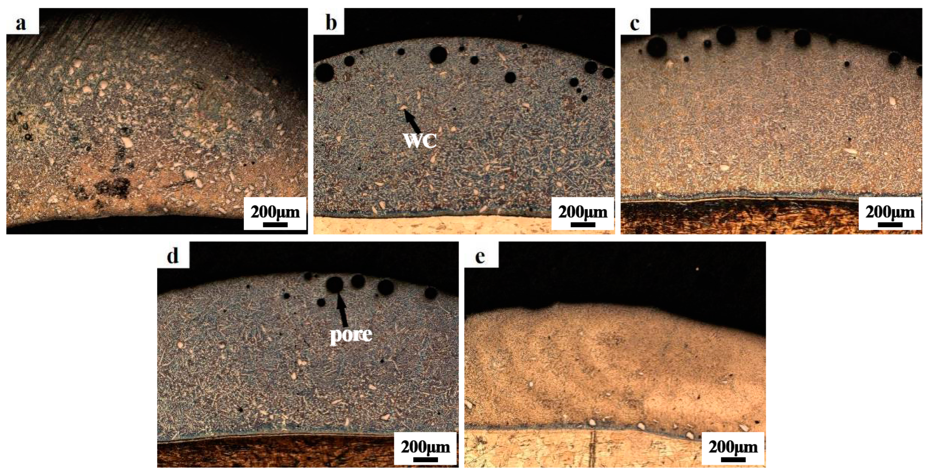
3.1. Macroscopic Forming and Crack Sensitivity of the Coating

Figure 2a shows a diagram of the typical macroscopic morphology of the coating produced by laser cladding. The forming parameters of the coating mainly include melting height (H), melting width (W), and melting depth (h). Dilution rate (η) refers to the extent to which the substrate metal melts into the coating in the laser cladding process, resulting in a change in the material composition of the coating. Its calculation is performed using the following Formula (2):
η = h / ( H + h ) × 100 %
Figure 2b,c display the macroscopic morphology and nondestructive testing results of the coatings with varying mass fractions of ZrW2O8. In coatings 1 to 5, the ZrW2O8 content is 0 wt%, 2 wt%, 4 wt%, 7 wt%, and 10 wt%, respectively. Nondestructive testing results indicate that as the ZrW2O8 content increases, the overall tendency for coating cracking gradually decreases. Notably, when the ZrW2O8 content reaches 7 wt% or 10 wt%, no cracks are observed in the cladding coating.
The cross-section morphology of the coatings is shown in Figure 3. As ZrW2O8 content increased, WC particles in the coating gradually melted, with the number of pores rising initially and then falling, and the thickness of the composite coating gradually decreasing. In actual production, it is necessary to polish the surface layer of the coating to a certain thickness. The influence of near-surface pores on the coating can be ignored. Therefore, when the addition of ZrW2O8 reaches 7% or 10%, the obtained crack-free coatings partially meet the requirements for practical applications to some extent.

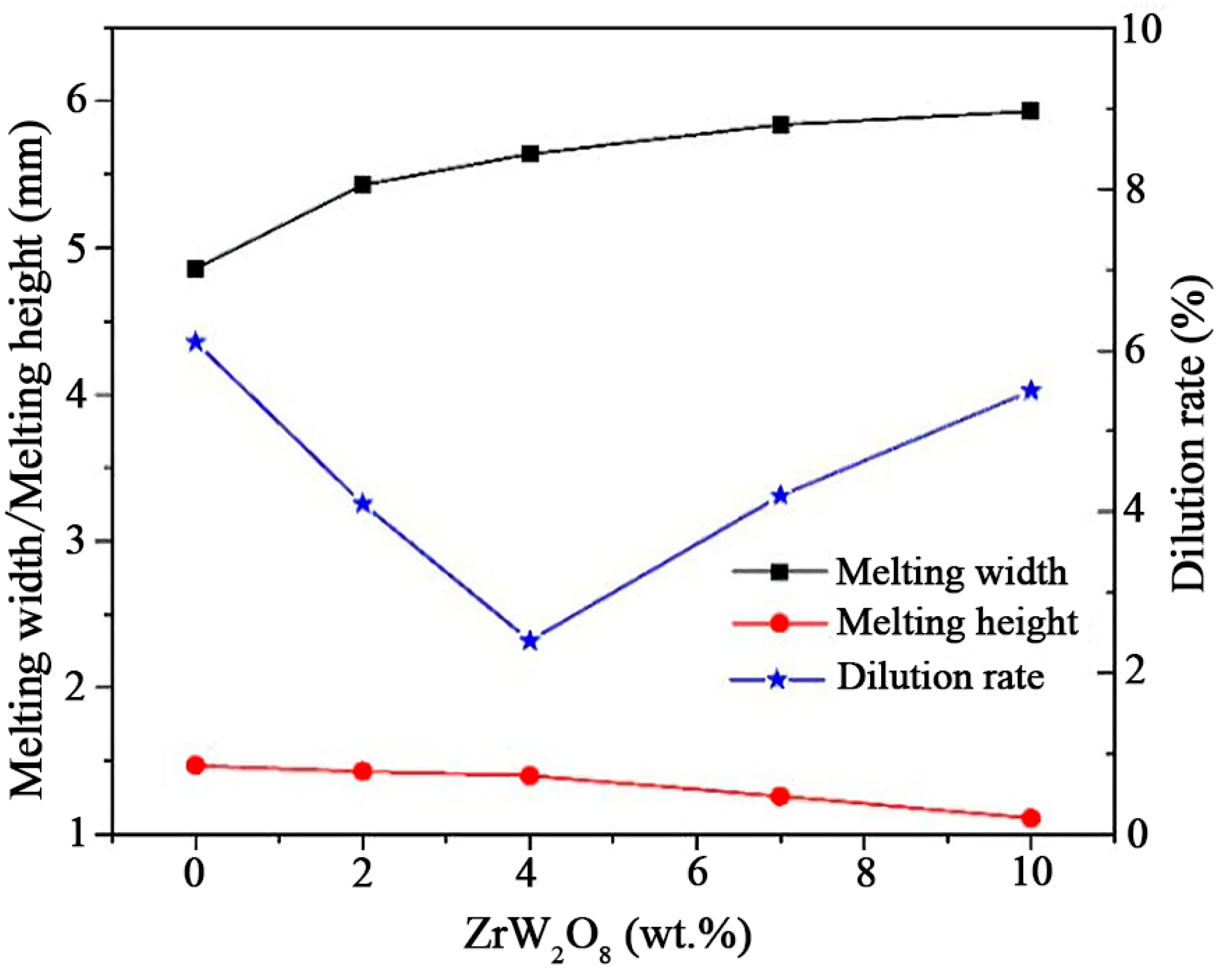
3.2. Melting Width, Melting Height, and Dilution Rate of Coating

Figure 4 illustrates the trends in melting width, melting height, and dilution rate of cladding coatings with varying ZrW2O8 contents. Due to its low density and small particle size, ZrW2O8 is prone to spattering under the influence of the laser beam and shielding gas. As the ZrW2O8 content increases, spattering becomes more pronounced, dissipating melting energy and resulting in a shallower melt depth of the substrate. When the ZrW2O8 content exceeds 4 wt%, spattering intensifies significantly, reducing the amount of molten powder in the pool. This enhances the dilution effect of the substrate, leading to a decrease in melting height and a subsequent increase in dilution rate. Additionally, the higher the content of ZrW2O8, a negative thermal expansion material, the lower the overall thermal expansion coefficient of the cladding material, thereby weakening the thermal expansion and contraction effect and increasing the melting width of the composite coating.

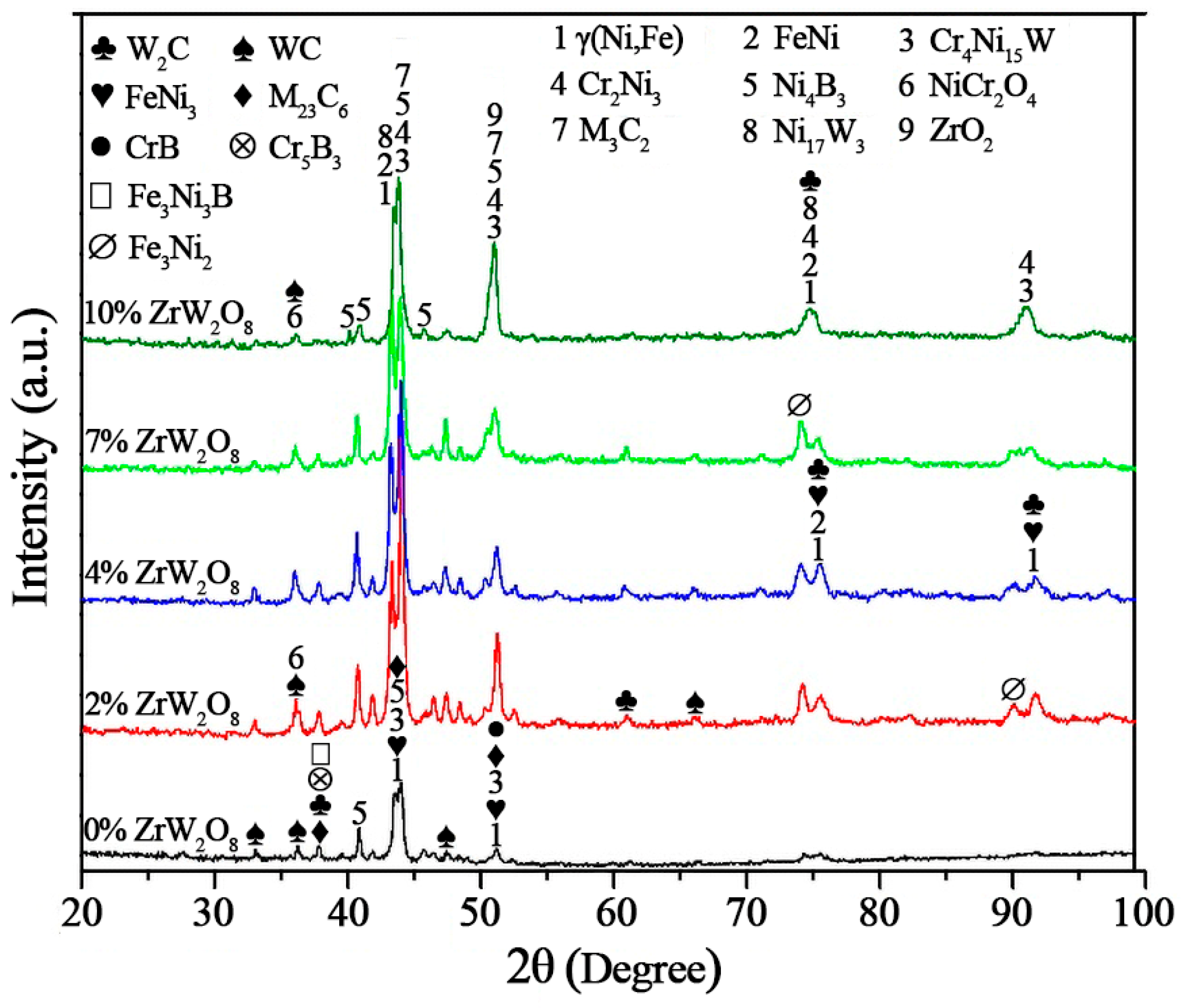
3.3. Phase Analysis of the Coating

Figure 5 shows the X-ray diffraction patterns of the coatings with different ZrW2O8 contents. The test results indicate that in the absence of ZrW2O8, the phases of the coating consist of γ (Ni,Fe), FeNi3, Cr4Ni15W, Ni4B3, M23C6, CrB, Cr5B3, Fe3Ni2, WC, and W2C, with the presence of W2C indicating WC decomposition. When the ZrW2O8 mass fractions are 2%, 4%, and 7%, the coating phases include γ (Ni,Fe), FeNi3, Cr4Ni15W, Ni4B3, M23C6, FeNi, M3C2, Ni17W3, Cr5B3, NiCr2O4, ZrO2, WC, and W2C. At a ZrW2O8 mass fraction of 10%, the phases are γ (Ni,Fe), FeNi, Ni17W3, Cr4Ni15W, Cr2Ni3, M3C2, Ni4B3, NiCr2O4, ZrO2, WC, and W2C. The XRD patterns reveal that as the ZrW2O8 content in the coating increases, WC is progressively eroded by the liquid metal matrix, leading to greater WC dissolution. This results in the recrystallization of free W and C elements with Cr, Fe, and Ni to form complex carbides, and an increase in W-containing compounds in the coating. Based on studies of the C-Cr-Fe quaternary alloy system [22] and experimental results, it is inferred that complex phase transitions may occur in the coating, including:
L W C + M 23 C 6 + γ N i , F e + C r 4 N i 15 W + N i 17 W 3
L + M 23 C 6 W C + M 3 C 2 + γ N i , F e + C r 4 N i 15 W + N i 17 W 3

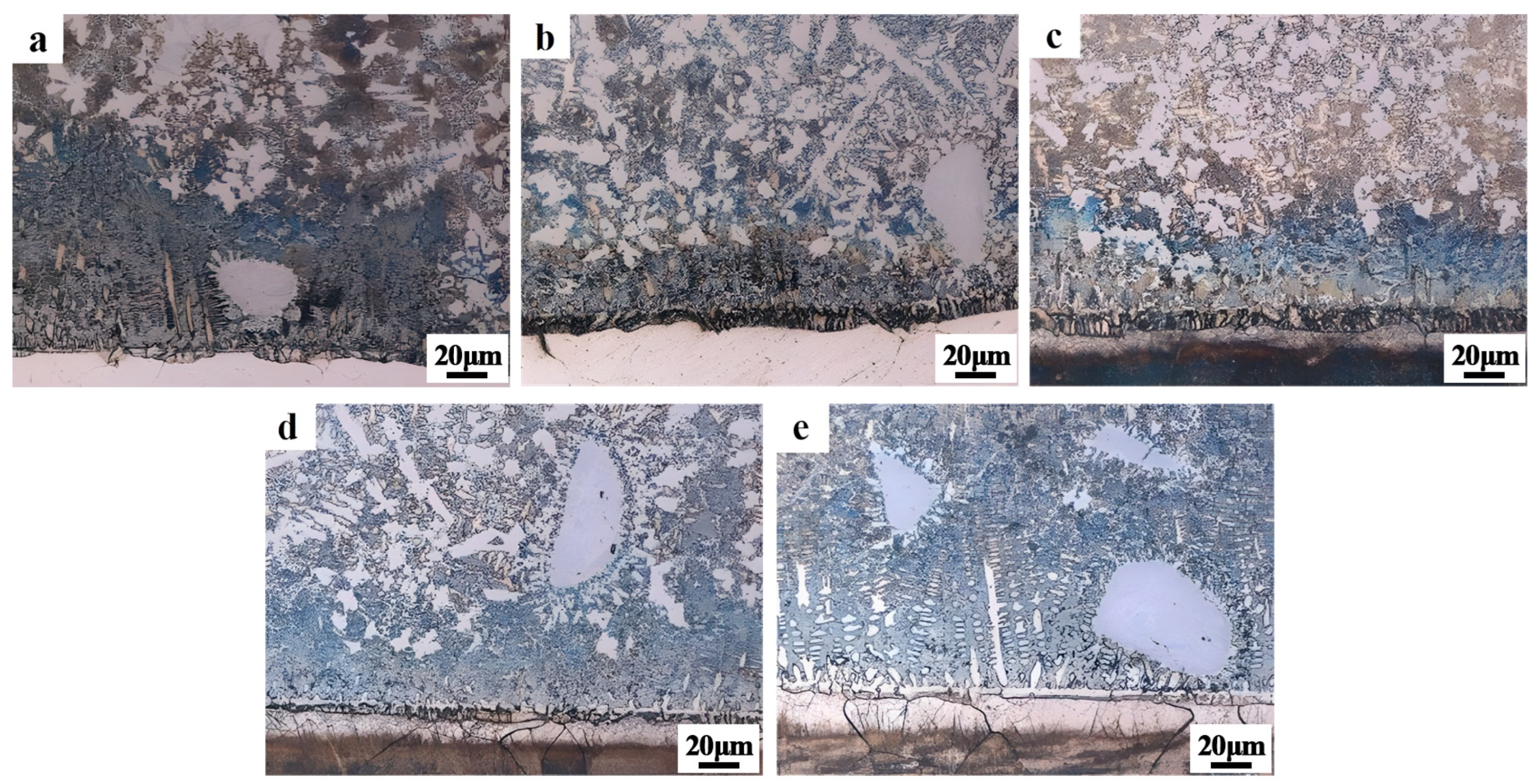
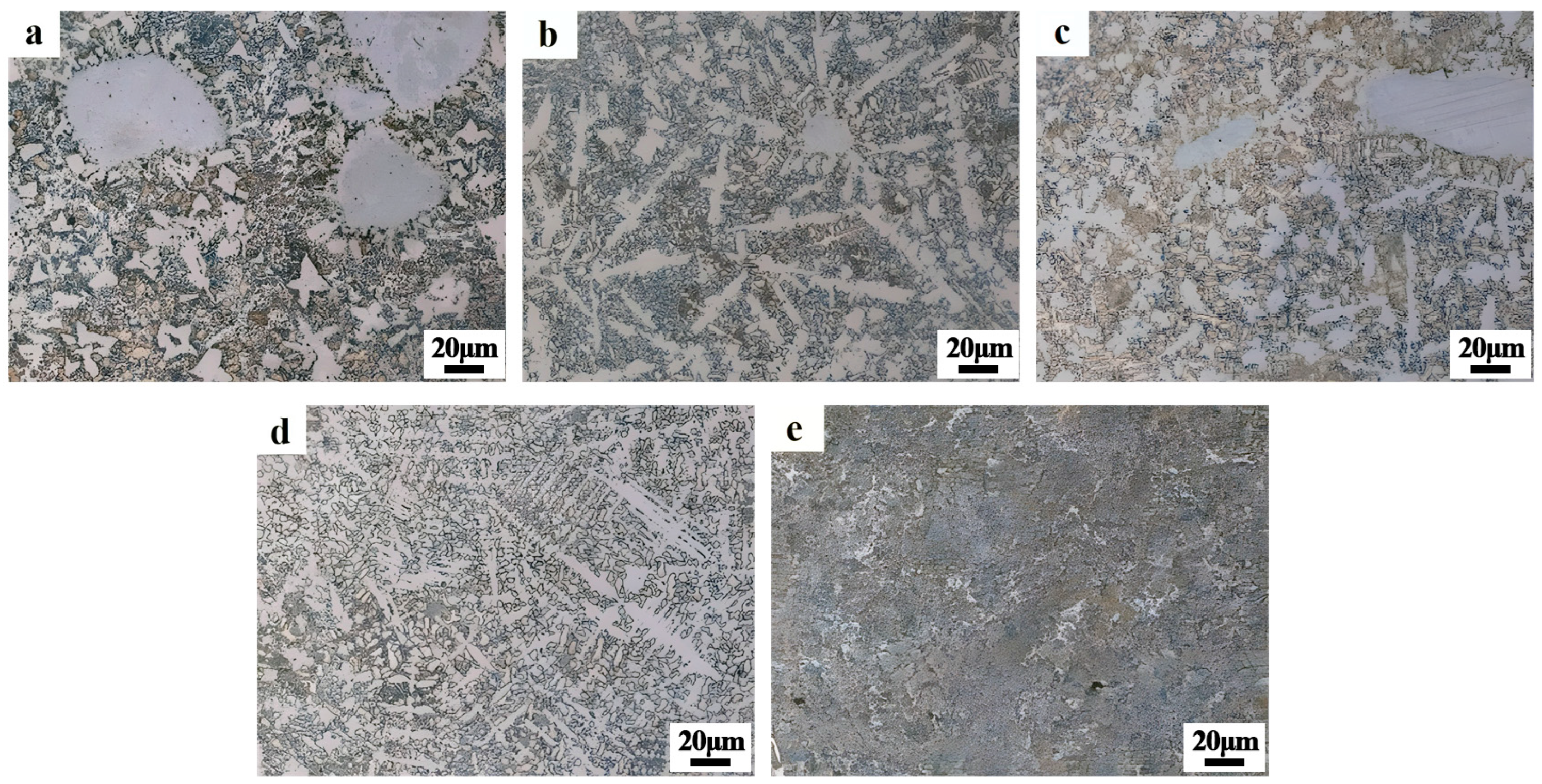
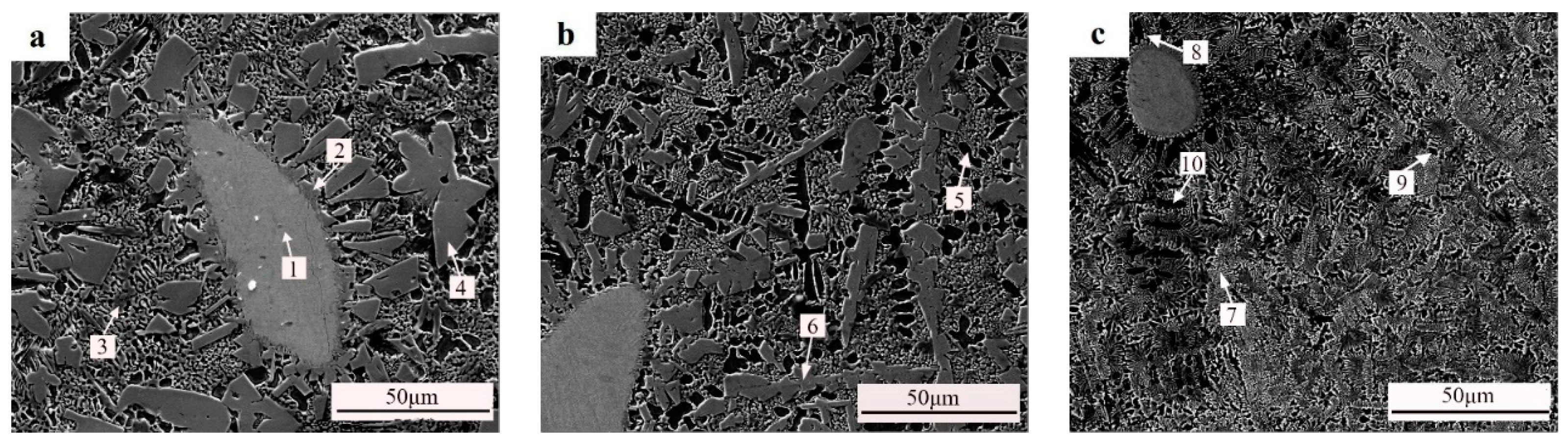
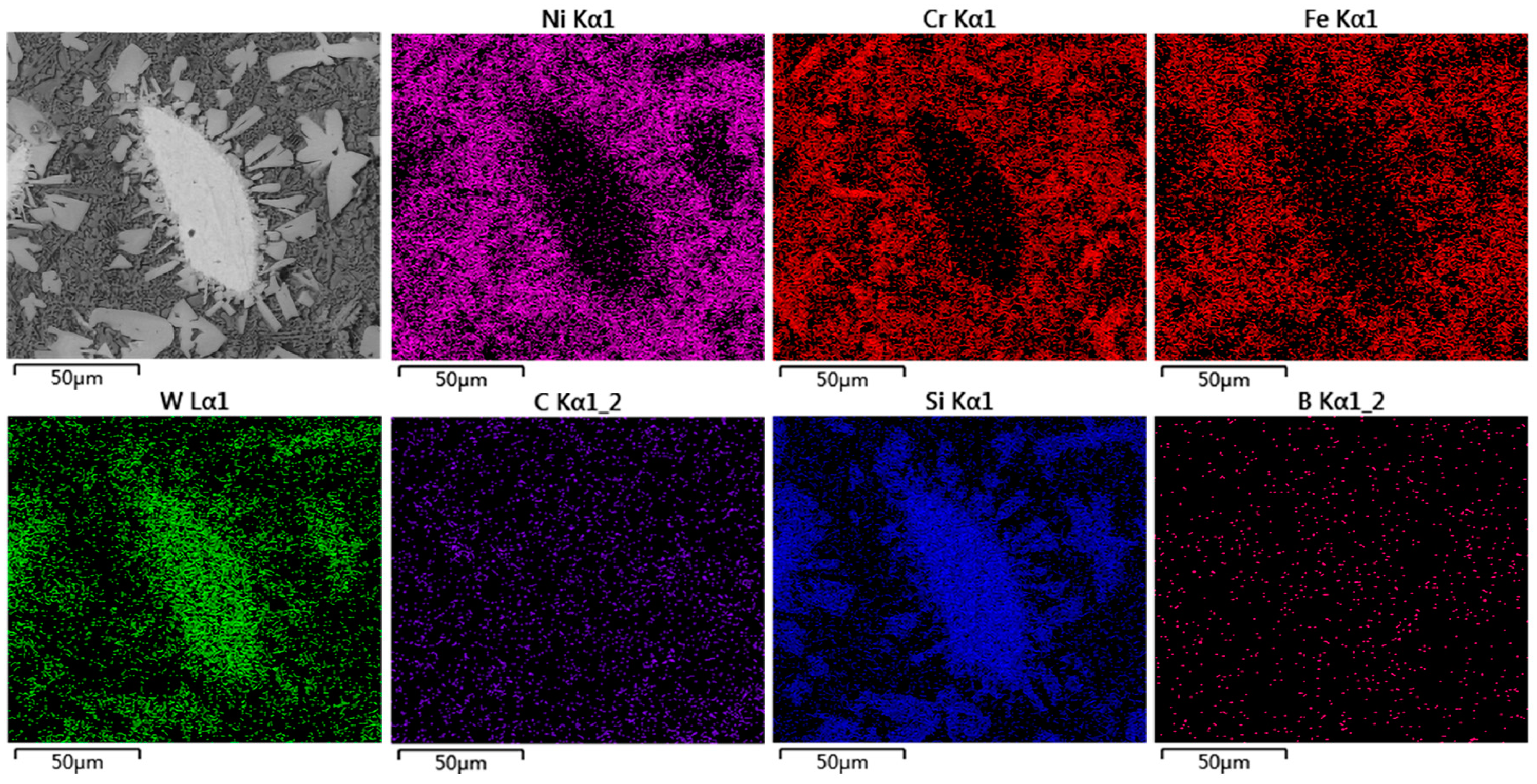
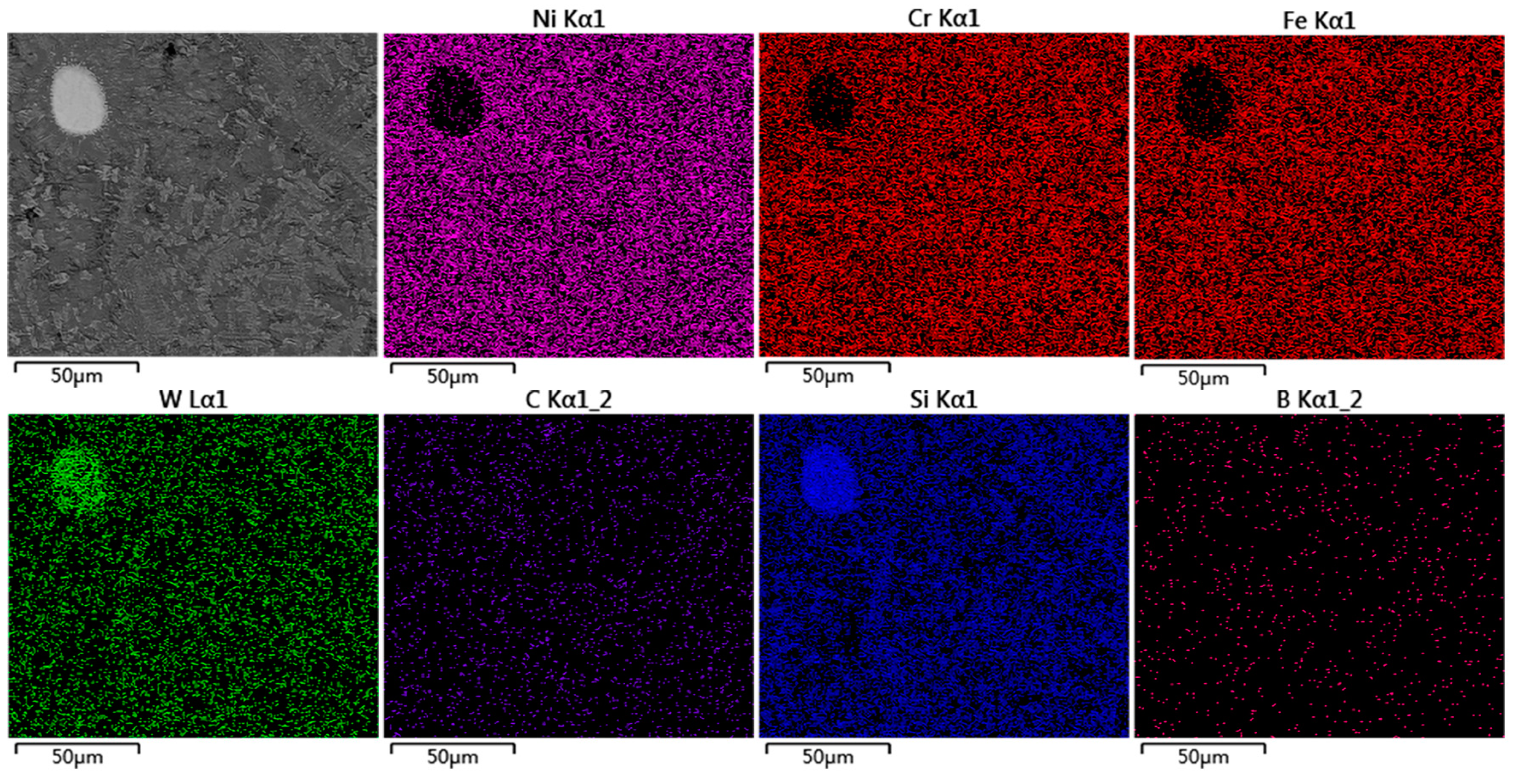
3.4. Microstructure of the Coating

Figure 6 and Figure 7 display the microstructure at the bottom, middle, and top of single-pass composite coatings with varying ZrW2O8 contents. Rapid solidification at the interface of the composite coatings forms a bright band of planar crystals, indicating atomic diffusion between the solution and the substrate, thus achieving metallurgical bonding. Independent fine-line regions within the coatings suggest that all samples have formed metallurgical bonds with the substrate.
The white particles in the images are unmelted WC particles; as the molten pool solidifies, the temperature around these particles drops, causing heat to flow toward them and resulting in micro-area directional cooling [23]. Consequently, the edges of the WC particles are composed of radially oriented blocky or rod-like structures.Without ZrW2O8, the bottom of the cladding layer mainly consists of epitaxially grown dendrites and inter-dendritic eutectic structures, with blocky, rod-like, and dendritic hard phases dispersed between the dendrites. The upper and middle parts primarily comprise dendrites and a few equiaxed crystals. As the ZrW2O8 content increases, the bottom dendrites gradually disappear, replaced by fine columnar crystals. The proportion of dendritic and equiaxed crystal structures in the cladding layer increases, with the grain structure becoming progressively refined, more uniform, and denser. The hard phases become more finely and uniformly dispersed among the dendrites.
Figure 8 presents the SEM microstructure of coatings with ZrW2O8 contents of 0%, 2%, and 10%, with the corresponding EDS results detailed in Table 4. Point 1 identifies a WC particle, and around its edges and the nearby matrix, many irregular needle-like, rod-like, petal-like, or blocky structures are observed at Points 2, 4, 6, and 8. These belong to carbide-hard phases such as M23C6 and M3C2. The dendritic structure at Point 7, dispersed throughout the cladding layer, is mainly composed of W, Ni, Cr, and Fe, forming hard phases like M3C2 and solid solution-strengthened products like Ni17W3 and Cr4Ni15W. Points 3, 5, 9, and 10 contain high concentrations of Ni and Fe, primarily constituting the γ (Ni,Fe) matrix phase. Notably, when the ZrW2O8 content is 10%, the upper layer of the cladding consists of finer WC particles and dendritic structures (Point 7). The middle layer is filled with fine, dense black particles (Point 9) and a small number of smaller rod-like structures (Point 10). The edges of the WC particles exhibit fine, blocky MxCy phases. The directionally solidified structure of the cladding layer with 10% ZrW2O8 is more uniform and denser than that of the layer without ZrW2O8. Grain refinement enhances the material’s plasticity and toughness, while the special directional structure inhibits crack propagation, grain boundary sliding, and dislocation movement [23]. Therefore, adding an appropriate amount of ZrW2O8 can improve the microstructure of the cladding layer and reduce the crack sensitivity of the cladding coating.
Figure 9 and Figure 10 show the EDS surface scanning results for Ni, Cr, Fe, W, C, Si, and B in samples without ZrW2O8 and with 10% ZrW2O8, respectively. Comparing Figure 9 and Figure 10, it is evident that local segregation occurs in the element distributions of the samples without ZrW2O8, whereas the sample with 10% ZrW2O8 shows a more uniform distribution of elements, particularly W.
These phenomena further indicate that the addition of a certain amount of ZrW2O8 can play a role in reducing the microstructure size of the coating and making the microstructure more uniform and finer, consistent with the results shown in Figure 8.
Combining the XRD results with the microstructure of the cladding coating reveals that adding ZrW2O8 to the composite powder increases WC dissolution, enhances the solid solution strengthening effect of W, refines the microstructure, and generates ZrO2 in situ. The addition of an appropriate amount of ZrW2O8 reduces the overall thermal expansion coefficient of the alloy powder, improving the coating’s resistance to residual stress. Additionally, ZrW2O8 decomposes into different ZrO2 phase structures under varying solidification conditions. During the laser cladding process, the stress-induced phase transformation of ZrO2 particles generates compressive stress on the main phase of the coating, halting crack propagation. Furthermore, the dispersed ZrO2 particles pin the cracks, causing deflection, twisting, and branching, dissipating the driving force of crack propagation. The in situ generated ZrO2 enhances the toughness of the coating and promotes crack self-healing [24,25]. Therefore, when an appropriate amount of ZrW2O8 is added, the phase transformation and dispersion of in situ generated ZrO2 play a crucial role in crack self-healing.

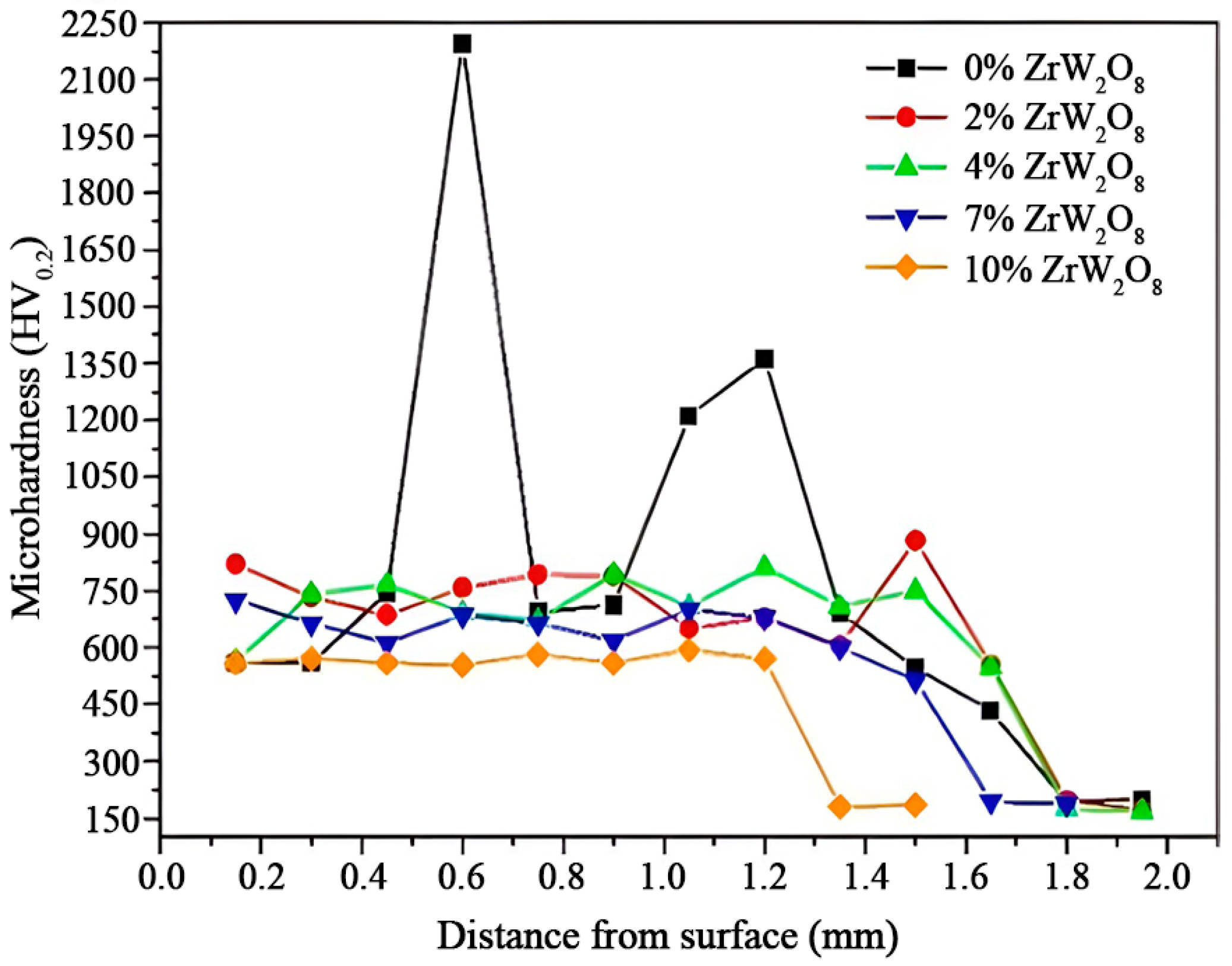
3.5. Microhardness of Coatings

Figure 11 presents the microhardness distribution curves of the cross-sectional coating with varying ZrW2O8 contents. As the amount of ZrW2O8 increases, the average microhardness of the coating gradually decreases, along with the fluctuating range of microhardness. When the addition of ZrW2O8 is 10%, the microhardness fluctuation of the coating is minimal, as is the average microhardness (570 HV0.2). The addition of ZrW2O8 refines the grains of the coating, resulting in a more uniform and finer structure, which enhances the solid solution strengthening effect of W. The hard phase disperses into the dendritic gaps with a fine structure. Moreover, the phase transformation toughening and dispersion toughening of ZrO2, induced by ZrW2O8 in the cladding coating, contribute to an increase in its density. However, the dissolution of WC particles and the formation of dendritic phases with high toughness and low hardness reduce the supporting effect of WC and the hard phases within the coating, leading to a decrease and stabilization in microhardness.

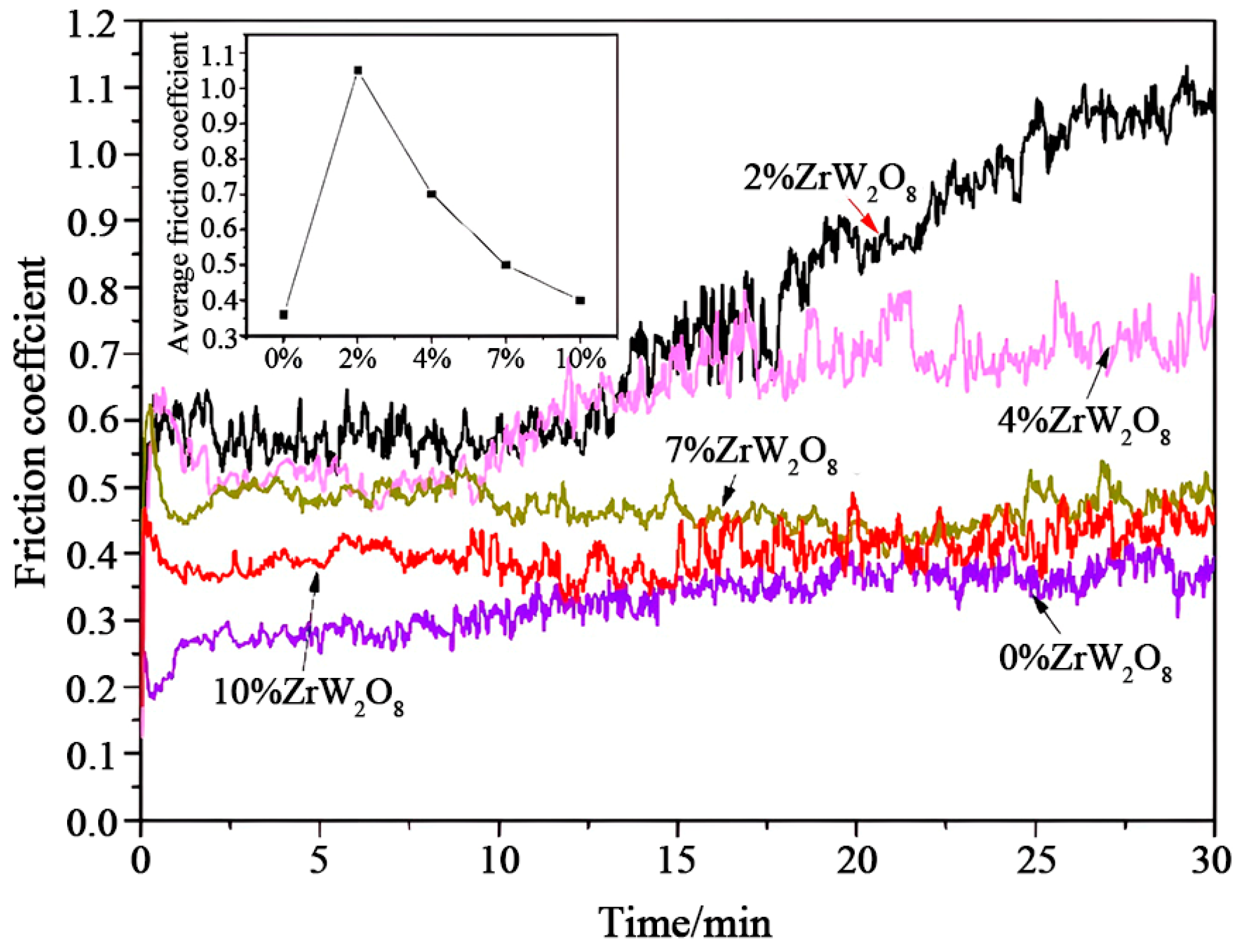
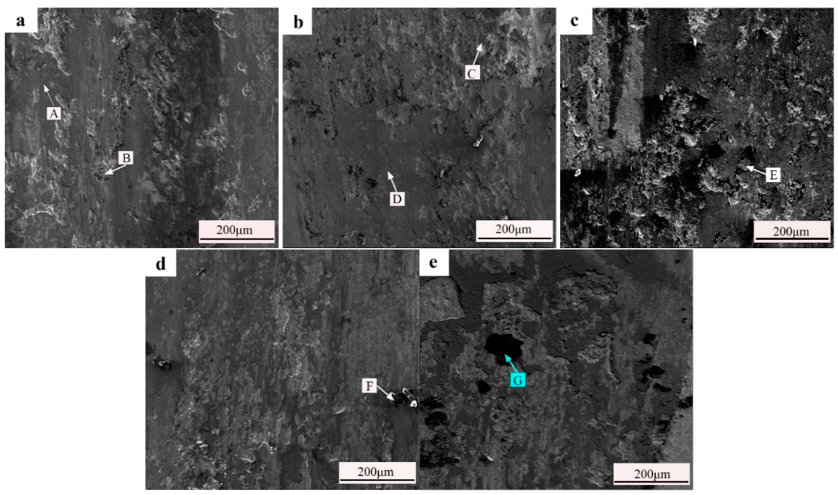
3.6. Wear Behaviors of Coatings

Figure 12 displays the wear curves of various samples under identical conditions. Initially, the wear coefficients of most samples are unstable but stabilize over time. The minimum wear coefficient values are observed in the coating without ZrW2O8. As the ZrW2O8 content increases, the amplitude of the wear curves initially rises and then decreases. When the other samples reach the stable wear stage, the wear coefficient of the sample with 2% ZrW2O8 remains in the rising stage and is higher. Conversely, the entire wear process of the coatings with 7% and 10% ZrW2O8 is steady.
Figure 13 illustrates the two-dimensional morphology of wear tracks and the volume wear rate of coatings after wear at various ZrW2O8 contents. It is observed that as the ZrW2O8 content in the coatings increases, both the maximum depth and maximum width of the wear tracks initially increase before decreasing. Simultaneously, the volume wear rate of the coatings also exhibits a trend of an initial increase followed by a decrease. At a ZrW2O8 content of 10%, the wear rate is minimized, indicating the highest wear resistance.
Figure 14 and Table 5 present SEM images and EDS analysis of the worn surfaces on the coatings. The coating without ZrW2O8 exhibits a few thin furrows and shallow adhesion pits. The combination of wear scar morphology and energy spectrum analysis reveals that the primary wear types are adhesive and oxidation wear. Figure 14b,c show adhesive pits and peeling layers caused by crack propagation and tearing. Analysis of point D indicates significant adhesive and fatigue wear, with slight oxidation wear, in the coatings with 2% and 4% ZrW2O8. Consequently, these coatings have higher wear rates, as shown in Figure 13b. When the ZrW2O8 content is between 7% and 10%, the main components of the spalling layers shift from γ (Ni,Fe) to boride and carbide, indicating strengthened γ (Ni,Fe) as the primary matrix. The worn surface of the coating with 7% ZrW2O8 is smooth, with minimal adhesive pits and peeling layers. In contrast, the coating with 10% ZrW2O8 shows only a few adhesive pits and no overall exfoliation.
When the ZrW2O8 content is low, numerous cracks form in the composite coating, compromising its microstructure and performance. This results in an unstable friction coefficient and a higher wear rate. However, when the ZrW2O8 content exceeds 7%, the crack sensitivity of the coating decreases, producing a fine, crack-free microstructure. The increased dissolution of WC-reinforced phases leads to the dispersion of small WC particles in the γ (Ni,Fe) matrix, enhancing its toughness. The dissolved WC particles further strengthen the γ (Ni,Fe) matrix through a new metallurgical reaction with Ni and Cr atoms, forming Ni17W3- and Cr4Ni15W-reinforced phases. These small, abundant reinforcement phases bear the main load during friction, reducing stress concentration and providing effective pinning reinforcement. Additionally, the unique, uniform directional structure formed by non-equilibrium solidification imparts high strength and toughness to the composite, improving its resistance to external scratches and preventing the penetration of abrasive particles. This uniform support mitigates crack formation and spalling during wear. In conclusion, the addition of ZrW2O8 not only avoids negative effects on the coating’s wear resistance but also ensures wear stability.

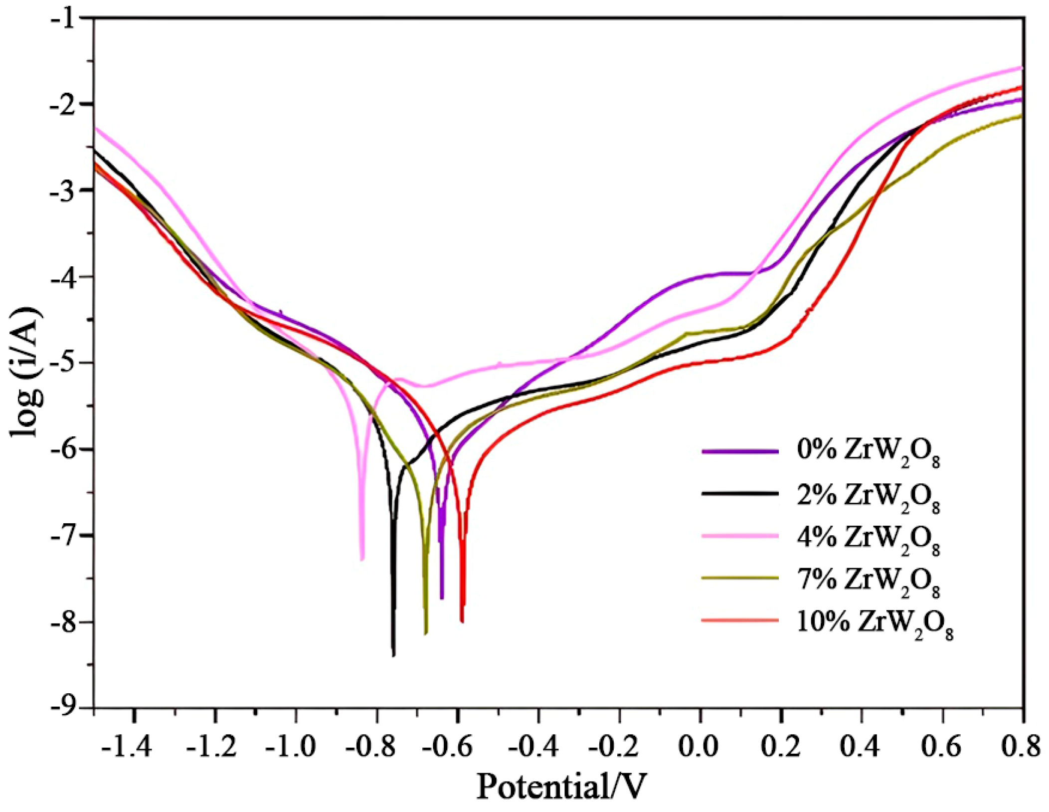
3.7. Electrochemical Measurements of Coatings

Figure 15 shows the potentiodynamic polarization curves of the coatings in a 3.5 wt% NaCl solution at room temperature. Table 6 lists the corrosion potential (Ecorr), corrosion current density (Icorr), and polarization resistance (Rp) of the investigated coatings. Lower Icorr, higher Ecorr, and higher Rp indicate better corrosion resistance. As seen in Figure 15 and Table 6, the earlier onset of the passivation zone, increased corrosion potential and polarization resistance, and decreased corrosion current density demonstrate that the add ition of ZrW2O8 significantly enhances the corrosion resistance of the Ni-based coating. Notably, the coating with 10% ZrW2O8 exhibits the highest corrosion resistance, while the coating with 4% ZrW2O8 shows the lowest.
When the ZrW2O8 content is low, defects such as microcracks, pores, impurities, and structural segregation in the coating impede the formation of a stable passivation film, enhancing electrochemical non-uniformity on the composite coating’s surface. This makes the coating susceptible to pitting, crevice, and grain boundary corrosion, significantly reducing its corrosion resistance [26]. When the ZrW2O8 content exceeds 7%, the coating exhibits fewer pores and suppressed cracks, diminishing pitting, crevice, and grain boundary corrosion. Moreover, the more evenly distributed elements, similar grain orientation, and fine microstructure enhance the nucleation sites for the passivation film, facilitating the formation of a dense passivation layer on the surface. Additionally, the increased solid solution of W in the coating’s dendrites improves its thermodynamic stability, reducing the number of galvanic cells. Consequently, the corrosion resistance of the coating with a ZrW2O8 content greater than 7% is significantly enhanced.

4. Conclusions

(1)
It is feasible to prepare crack-free laser cladding layers by adding the negative thermal expansion coefficient powder material ZrW2O8 to the Ni60/WC mixed powder.
(2)
When the mass fractions of ZrW2O8 in the cladding layer are 2% and 4%, the degree of negative thermal expansion effect accumulation is small, and the in situ generated ZrO2 is insufficient to fully suppress and close the cracks. However, adding ZrW2O8 with mass fractions of 7% and 10% can achieve crack-free cladding layers. Nonetheless, as the ZrW2O8 content continues to increase, it leads to a decrease in the wettability of the composite powder, resulting in more powder losses due to spattering, which is detrimental to the preparation of the cladding layer. Therefore, as a crack inhibitor, the amount of ZrW2O8 powder should be minimized as much as possible without causing cracks, with 10% being the optimal amount in this study. During the laser cladding process, ZrW2O8 decomposes in situ to form ZrO2. The phase transformation of ZrO2 particles exerts compressive stress on the main phase of the cladding layer. This compressive effect on cracks is the primary reason for the suppression and self-healing of cracks.
(3)
In the process of preparing laser cladding coatings, incorporating in situ phase-transformable negative thermal expansion materials to achieve crack self-healing is a promising research direction for addressing the issue of cracking in cladding coatings.

Author Contributions

Conceptualization, P.Z. and Y.P.; methodology, P.Z.; investigation, C.L.; resources, Y.P.; data curation, Y.P.; writing—original draft preparation, C.L.; writing—review and editing, P.Z.; visualization, C.L.; funding acquisition, C.L. All authors have read and agreed to the published version of the manuscript.

Funding

This research was funded by the Major Science and Technology Projects in Gansu Province (No.22ZD6GA008).

Institutional Review Board Statement

Not applicable.

Informed Consent Statement

Not applicable.

Data Availability Statement

The data that support the findings of this study are available from the corresponding author upon reasonable request.

Conflicts of Interest

The authors declare no conflicts of interest.

References

  1. Riquelme, A.; Rodrigo, P.; Escalera-Rodriguez, M.D.; Rams, J. Evaluation of the Wear Resistance and Corrosion Behavior of Laser Cladding Al/SiC Metal Matrix Composite Coatings on ZE41 Magnesium Alloy. Coatings 2021, 11, 639. [Google Scholar] [CrossRef]
  2. Zhang, Z.; Yu, T.; Kovacevic, R. Erosion and corrosion resistance of laser cladded AISI 420 stainless steel reinforced with VC. Appl. Surf. Sci. 2017, 410, 225–240. [Google Scholar] [CrossRef]
  3. Zhao, Y.; Lu, M.; Fan, Z.; Huang, S.; Huang, H. Laser deposition of wear-resistant titanium oxynitride/titanium composite coatings on Ti-6Al-4V alloy. Appl. Surf. Sci. 2020, 531, 147–212. [Google Scholar] [CrossRef]
  4. Zhang, P.; Pang, Y.; Yu, M. Effects of WC Particle Types on the Microstructures and Properties of WC-Reinforced Ni60 Composite Coatings Produced by Laser Cladding. Metals 2019, 9, 583. [Google Scholar] [CrossRef]
  5. Guo, C.; Chen, J.; Zhou, J.; Zhao, J.; Wang, L.; Yu, Y.; Zhou, H. Effects of WC–Ni content on microstructure and wear resistance of laser cladding Ni-based alloys coating. Surf. Coat. Technol. 2012, 206, 2064–2071. [Google Scholar] [CrossRef]
  6. Karmakar, D.P.; Muvvala, G.; Nath, A.K. High-temperature abrasive wear characteristics of H13 steel modified by laser remelting and cladded with Stellite 6 and Stellite 6/30% WC. Surf. Coat. Technol. 2021, 422, 127498. [Google Scholar] [CrossRef]
  7. Chen, C.; Feng, A.; Wei, Y.; Wang, Y.; Pan, X.; Song, X. Effects of WC particles on microstructure and wear behavior of laser cladding Ni60 composite coatings. Opt. Laser Technol. 2023, 163, 109425. [Google Scholar] [CrossRef]
  8. Li, W.; Yang, X.; Xiao, J.; Hou, Q. Effect of WC mass fraction on the microstructure and friction properties of WC/Ni60 laser cladding layer of brake discs. Ceram. Int. 2021, 47, 28754–28763. [Google Scholar] [CrossRef]
  9. Lee, C.; Park, H.; Yoo, J.; Lee, C.; Woo, W.; Park, S. Residual stress and crack initiation in laser clad composite layer with Co-based alloy and WC+NiCr. Appl. Surf. Sci. 2015, 345, 286–294. [Google Scholar] [CrossRef]
  10. Shen, X.; Peng, H.; Xue, Y.; Wang, B.; Su, G.; Zhu, J.; Li, A. Microstructure and Properties of WC/Ni-Based Laser-Clad Coatings with Different WC Content Values. Materials 2022, 15, 6309. [Google Scholar] [CrossRef]
  11. Alidokht, S.A.; Yue, S.; Chromik, R.R. Effect of WC morphology on dry sliding wear behavior of cold-sprayed Ni-WC composite coatings. Surf. Coat. Technol. 2019, 357, 849–863. [Google Scholar] [CrossRef]
  12. Fernández, M.; García, A.; Cuetos, J.; González, R.; Noriega, A.; Cadenas, M. Effect of actual WC content on the reciprocating wear of a laser cladding NiCrBSi alloy reinforced with WC. Wear 2015, 324–325, 80–89. [Google Scholar] [CrossRef]
  13. Wang, X.; Rong, J.; Yao, Y.; Zhang, Y.; Zhong, Y.; Feng, J.; Yu, X.; Zhan, Z. La doping inhibits stress production at the grain boundaries in Ni–WC coating. J. Alloys Compd. 2018, 753, 688–694. [Google Scholar] [CrossRef]
  14. Qunshuang, M.; Yajiang, L.; Juan, W.; Kun, L. Microstructure evolution and growth control of ceramic particles in wide-band laser clad Ni60/WC composite coatings. Mater. Des. 2016, 92, 897–905. [Google Scholar] [CrossRef]
  15. Yang, X.; Cheng, X.; Yan, X.; Yang, J.; Fu, T.; Qiu, J. Synthesis of ZrO2/ZrW2O8 composites with low thermal expansion. Compos. Sci. Technol. 2007, 67, 1167–1171. [Google Scholar] [CrossRef]
  16. Peng, Z.; Sun, Y.; Peng, L. Hydrothermal synthesis of ZrW2O8 nanorods and its application in ZrW2O8/Cu composites with controllable thermal expansion coefficients. Mater. Des. 2014, 54, 989–994. [Google Scholar] [CrossRef]
  17. Zhou, C.; Zhang, Q.; Liu, S.; Zhou, T.; Jokisaari, J.R.; Wu, G. Microstructure and thermal expansion analysis of porous ZrW2O8/Al composite. J. Alloys Compd. 2016, 670, 182–187. [Google Scholar] [CrossRef]
  18. Wang, X.; Zhang, J.; Zhang, Y.; Zhang, J.; Lu, F.; Wang, X. Synthesis and thermal expansion of 4J36/ZrW2O8 composites. Rare Met. 2010, 29, 371–375. [Google Scholar] [CrossRef]
  19. Islam, M.S.; Chang, W.; Sha, Z.; Wang, J.; Wu, S.; Rose, L.F.; Kinloch, A.J.; Wang, C.H. Mitigating cryogenic microcracking in carbon-fibre reinforced polymer composites using negative thermal-expansion nanoparticles functionalized by a polydopamine coating. Compos. Part B Eng. 2023, 257, 110676. [Google Scholar] [CrossRef]
  20. Wu, Y.; Wang, M.; Chen, Z.; Ma, N.; Wang, H. The effect of phase transformation on the thermal expansion property in Al/ZrW2O8 composites. J. Mater. Sci. 2013, 48, 2928–2933. [Google Scholar] [CrossRef]
  21. Qi, K.; Yang, Y.; Hu, G.; Lu, X.; Li, J. Thermal expansion control of composite coatings on 42CrMo by laser cladding. Surf. Coat. Technol. 2020, 397, 125983. [Google Scholar] [CrossRef]
  22. Gustafson, P. A thermodynamic evaluation of the C–Fe–W system. Metall. Mater. Trans. A 1987, 18, 175–188. [Google Scholar] [CrossRef]
  23. Yang, X.; Li, X.; Yang, Q.; Wei, H.; Fu, X.; Li, W. Effects of WC on microstructure and corrosion resistance of directional structure Ni60 coatings. Surf. Coat. Technol. 2020, 385, 125359. [Google Scholar] [CrossRef]
  24. Mary, T.A.; Evans, J.S.O.; Vogt, T.; Sleight, A.W. Negative Thermal Expansion from 0.3 to 1050 Kelvin in ZrW2O8. Science 1996, 272, 90–92. [Google Scholar] [CrossRef]
  25. Zhou, C.; Zhang, Q.; Zhang, M.; Wu, G. In-situ Raman spectroscopy study of thermal mismatch stress and negative thermal expansion behaviours of ZrW2O8 in ZrW2O8/Al composite. J. Alloys Compd. 2017, 718, 356–360. [Google Scholar] [CrossRef]
  26. Wang, H.; Lu, H.; Song, X.; Yan, X.; Liu, X.; Nie, Z. Corrosion resistance enhancement of WC cermet coating by carbides alloying. Corros. Sci. 2019, 147, 372–383. [Google Scholar] [CrossRef]
Figure 1. Secondary electron (SE) mode SEM images of the powder used for cladding: (a) Ni60 powder; (b) WC particles; (c) ZrW2O8 powder.
Coatings 14 00649 g001
Figure 2. (a) Diagram of typical macroscopic morphology; (b) the macroscopic morphology; (c) crack detection results of the coatings.
Coatings 14 00649 g002
Figure 3. Microstructure and the distribution of WC particles in the coating (a) 0% ZrW2O8; (b) 2% ZrW2O8; (c) 4% ZrW2O8; (d) 7% ZrW2O8; (e) 10% ZrW2O8.
Coatings 14 00649 g003
Figure 4. Effects of ZrW2O8 content on surface formation of the coating.
Coatings 14 00649 g004
Figure 5. XRD pattern of the coating.
Coatings 14 00649 g005
Figure 6. The bottom microstructures of coatings with different ZrW2O8 contents: (a) 0% ZrW2O8; (b) 2% ZrW2O8; (c) 4% ZrW2O8; (d) 7% ZrW2O8; (e) 10% ZrW2O8.
Coatings 14 00649 g006
Figure 7. The middle and upper microstructures of coatings with different ZrW2O8 contents: (a) 0% ZrW2O8; (b) 2% ZrW2O8; (c) 4% ZrW2O8; (d) 7% ZrW2O8; (e) 10% ZrW2O8.
Coatings 14 00649 g007
Figure 8. Backscattered electron (BSE) mode SEM microstructures of the coating with varying ZrW2O8 contents: (a) 0% ZrW2O8; (b) 2% ZrW2O8; (c) 10% ZrW2O8.
Coatings 14 00649 g008
Figure 9. Distribution maps of elemental composition within the coating without ZrW2O8.
Coatings 14 00649 g009
Figure 10. Distribution maps of elemental composition within the coating containing 10% ZrW2O8.
Coatings 14 00649 g010
Figure 11. Microhardness distribution of the coating.
Coatings 14 00649 g011
Figure 12. Friction coefficient curve of the coating.
Coatings 14 00649 g012
Figure 13. (a) Characteristic wear tracks of the investigated coatings after the wear test and (b) the variation of wear rates for different samples.
Coatings 14 00649 g013
Figure 14. Backscattered electron (BSE) mode SEM images of wear traces on the coatings (a) 0% ZrW2O8; (b) 2% ZrW2O8; (c) 4% ZrW2O8; (d) 7% ZrW2O8; (e) 10% ZrW2O8.
Coatings 14 00649 g014
Figure 15. The potentiodynamic polarization curves of composite coatings.
Coatings 14 00649 g015
Table 1. Chemical composition of stainless steel (wt%).
SPCSiMnNiCrFe
0.030.0450.07–0.080.075–128–1118–20Bal
Table 2. Chemical composition of Ni60 powder (wt%).
CWBSiFeCrNi
0.803.003.504.0015.0015.00Bal
Table 3. Composition ratio of ZrW2O8/WC/Ni60 cladding materials and process parameters in laser cladding.
SampleComposition (wt%)Parameters for the Laser Cladding Process
Ni60WC ZrW2O8 Laser Power (w)Scanning Speed (mm/s)Powder Feeding Voltage (v)ΔZ (mm)
1703001500120719
268.629.42
366.229.84
463.129.97
560.729.310
Table 4. EDS analysis results of the coating (wt%).
PointWFeCrNiBSiCZrO
191.1-----8.9--
256.43.913.115.42.11.87.3--
31.616.45.160.42.03.511.1--
457.85.618.94.67.6-5.5--
52.919.77.362.00.52.34.4-0.7
656.03.411.419.9-2.65.70.60.4
731.614.414.824.42.82.07.90.81.3
863.04.918.16.6--6.80.6-
92.827.75.856.11.80.34.4-1.1
107.527.89.248.9-1.93.60.20.9
Table 5. The relative EDS results are shown in Figure 14 (wt%).
PointWFeCrNiBSiCZrO
A14.314.23.034.6-2.78.9-20.1
B8.017.712.938.6-1.717.4-3.9
C7.77.65.274.5--1.8-3.2
D25.17.47.232.3--9.9-18.1
E-13.96.050.220.32.15.3-2.2
F-1.10.71.625.50.563.7-6.8
G-5.03.07.622.42.456.60.22.8
Table 6. The corresponding electrochemical parameters of composite coatings.
SampleEcorr/VIcorr × 10−6/(A·cm−2)Rp/(Ω·cm−2)
0% ZrW2O8−0.6412.2230,604.4
2% ZrW2O8−0.7591.2428,923.6
4% ZrW2O8−0.8939.729991.8
7% ZrW2O8−0.6831.7662,437.6
10% ZrW2O8−0.5881.7252,495.4
Disclaimer/Publisher’s Note: The statements, opinions and data contained in all publications are solely those of the individual author(s) and contributor(s) and not of MDPI and/or the editor(s). MDPI and/or the editor(s) disclaim responsibility for any injury to people or property resulting from any ideas, methods, instructions or products referred to in the content.

