Article

Investigating the Impact of Physical Vapour Deposition (PVD)-Coated Cutting Tools on Stress Corrosion Cracking Susceptibility in Turning Super Duplex Stainless Steel

1
McMaster Manufacturing Research Institute (MMRI), McMaster University, Hamilton, ON L8S 4L8, Canada
2
Mechanical Engineering Department, King Fahd University of Petroleum and Minerals, Dhahran 31261, Saudi Arabia
3
Department of Materials Science and Engineering, McMaster University, Hamilton, ON L8S 4L8, Canada
*
Authors to whom correspondence should be addressed.
These authors contributed equally to this work.
Coatings 2024, 14(3), 290; https://doi.org/10.3390/coatings14030290
Submission received: 2 February 2024 / Revised: 22 February 2024 / Accepted: 26 February 2024 / Published: 28 February 2024
(This article belongs to the Special Issue Corrosion/Wear Mechanisms and Protective Methods)

Abstract

:
This work aimed to ascertain the corresponding influences of several PVD-coated cutting tools on the susceptibility of the machined surface of super duplex stainless steel (SDSS) to stress corrosion cracking. Coatings comprised of AlCrN, AlCrN/TiSiN, and AlTiN were applied to cemented carbide cutting tools using the PVD method; these were then used to turn the outer surface of the SDSS tube section. During the cutting process, the material presents the following combination of features: (i) a tendency for strain hardening, reflected in microstructural modifications and residual stresses of the machined surface and (ii) high temperatures in the cutting region, reducing the tool life. The goal of this work was to evaluate the surface integrity (work hardening and corrosion behaviour) of the SDSS obtained after the machining process (finish turning) with cemented carbide tools coated with three different PVD coatings.

1. Introduction

Due to their dual-phase microstructure (ferrite and austenite) and highly Cr-, Mo-, and N-rich chemical composition, duplex stainless steels (DSS) exhibit a combination of exceptionally high mechanical strength and toughness with comparatively low localized corrosion susceptibility [1,2]. This combination of material properties has made DSS a material of choice for many components in contact with aggressive process solutions encountered in various industries, including oil and gas, pulp and paper, chemical processing, and energy generation [2,3,4]. However, stress corrosion cracking (SCC) susceptibility, particularly so when exposed to hot, concentrated aqueous chloride solutions, remains a key material’s performance concern given the unpredictability of this failure mode [5,6,7,8].
Final machining operations such as grinding, turning, or milling applied to DSS surfaces have been shown to strongly affect chloride SCC susceptibility [8,9,10,11]. Surface grinding of 22Cr and 25Cr DSS was found to promote the formation of a nano-crystalline surface layer, which was prone to dealloying (selective dissolution of Fe), leading to a stress-induced brittle cracking of the layer with an applied load under evaporative seawater conditions. Dealloying, rather than pitting, was implicated as the precursor for SCC (micro-crack formation), which was restricted to the ferrite phase. Surface grinding of 23Cr DSS was also found to strongly affect micro-crack formation when immersed in boiling MgCl2 (aq) [8]. Micro-cracking occurred both with and without an applied load, which led to the conclusion that grinding-induced tensile residual stresses were the critical factors [9]. Both phases suffered micro-cracking and the extent was generally restricted to a thickness of several micrometres corresponding to the highly deformed surface layer induced by the grinding operation. Dry turning of 25Cr DSS was also shown to induce micro-cracking without an applied load in boiling MgCl2 (aq) [12]. Tensile residual stresses generated during the turning operation were also implicated as the critical factors. Micro-cracking occurred in both phases, but the extent to which it occurred was higher in the ferrite phase [10]. The use of a lubricant during the turning of 25Cr DSS was found to be beneficial in reducing the tendency for micro-crack formation without an applied load in boiling MgCl2 (aq). The beneficial effect was attributed to a lower tensile residual stress state relative to the case without a lubricant (dry turning) [11].
Both residual stress accumulation and surface microstructure deformation are consequences of the relatively poor machinability of DSS [13,14,15,16]. Key material properties that contribute to the poor machinability of DSS include low thermal conductivity, high toughness, and a high work hardening rate, which combine to produce excessive thermal and mechanical loads during machining that promotes workpiece–tool adhesion and an associated built-up edge (BUE) formation on the cutting tool [16,17]. Such formation demands a higher cutting force for continued machining, which adversely affects chip flow and promotes chipping of the cutting edge [18]. The end result is a shortened cutting length (tool lifetime) and a machined workpiece surface with poor quality. It has been demonstrated that an efficient way to increase the machinability of DSS by extending the tool lifespan is to apply a thin protective ceramic coating using physical vapour deposition (PVD) or chemical vapour deposition (CVD) on the tool insert (usually cemented carbide) [19,20,21,22]. For turning operations applied to 25Cr DSS workpieces, for example, the application of a thin AlTiN coating to a cemented carbide tool insert using PVD has been shown to increase the tool lifespan three times longer than an uncoated insert [20,23]. The improved insert performance was attributed to the low coefficient of friction of the applied thin AlTiN coating, which improved chip removal, lowered the cutting force, and reduced tool wear.
Despite the improvements to machinability, the practice of applying a thin hard ceramic coating to a cemented carbide tool insert to machine 25Cr DSS cannot be considered a success without determining the associated corrosion susceptibility of the machined surface. While studies have been reported on the pitting corrosion [24] and chloride SCC [11] susceptibility of 25Cr DSS machined with a ceramic-coated cermet insert, the focus was placed on the effect of the cutting speed and coolant pressure and on different coolant environments, respectively, rather than on the effect of the ceramic coating applied to the insert. Thus, the objective of this work was to determine the relative effects of different PVD-coated cermet inserts used to turn the surface of 25Cr DSS on the associated chloride SCC susceptibility. Thin ceramic coatings comprised of AlCrN, AlCrN/TiSiN, and AlTiN were applied to a cermet insert using PVD and were investigated for this purpose.

2. Materials and Methods
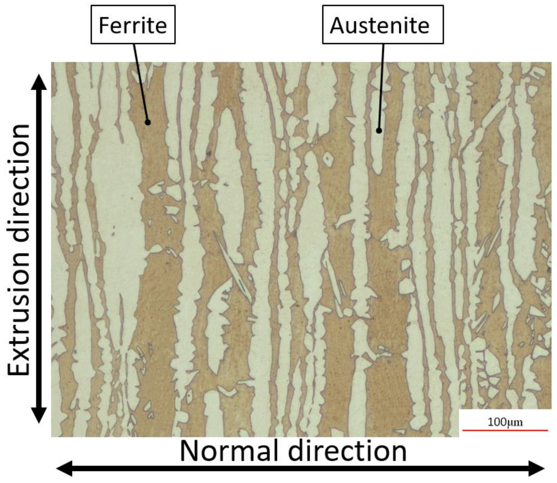
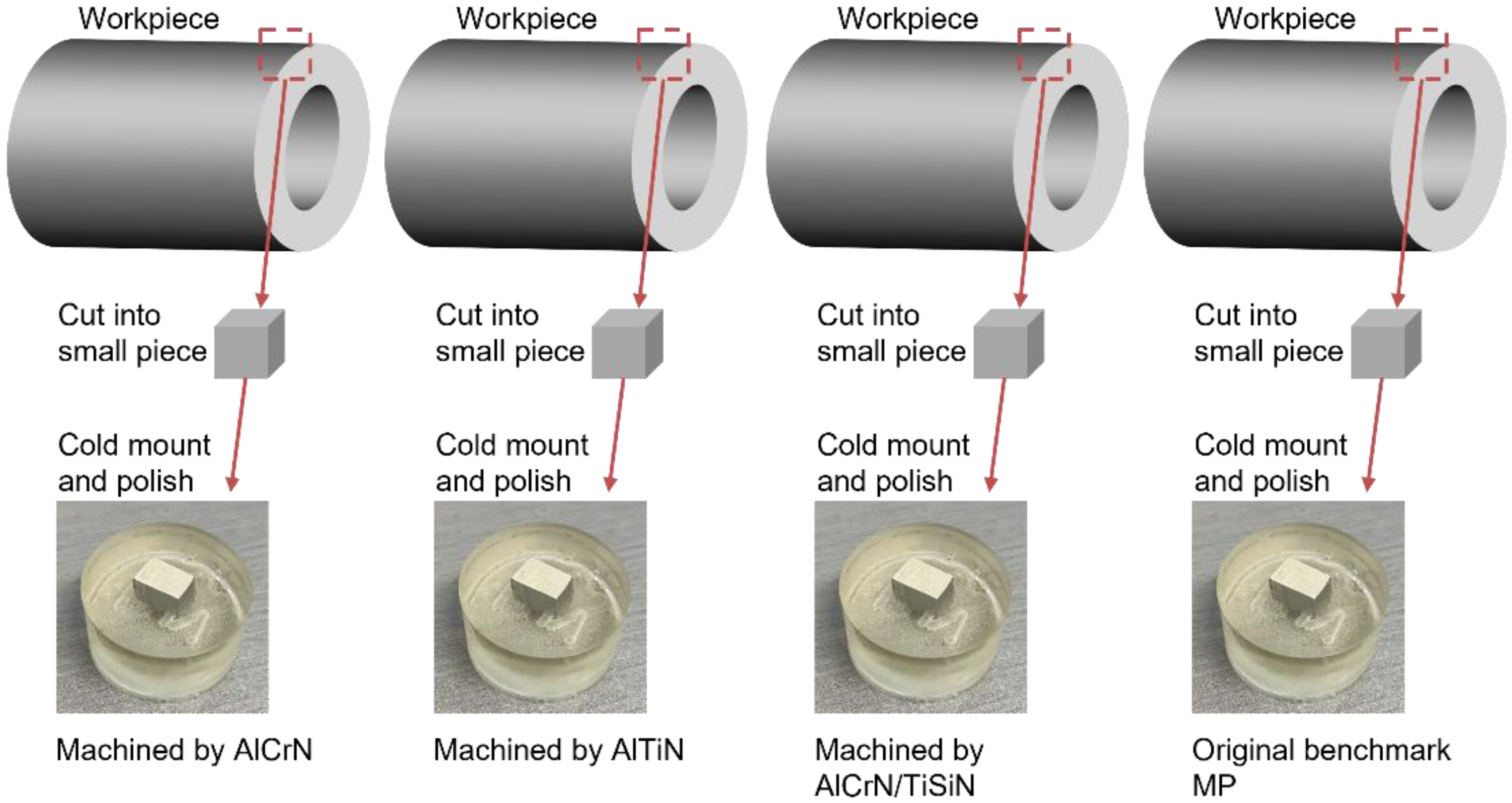
2.1. Materials

Workpiece test samples (100 mm in length) were prepared from a section of a commercial Type 2507 (25Cr) SDSS seamless tube product (176 mm outer diameter and 22 mm wall thickness) provided by V&M Tubes Solutions. The composition of the major alloying elements taken from the tube product’s mill certificate is listed in Table 1.
Figure 1 shows a light optical microscopy image of the etched cross-sectional microstructure, within which the co-existing ferrite (dark) and austenite (light) phases are clearly apparent.
Tubular Type 2507 SDSS workpiece surfaces were machined (turned) using a Nakamura-Tome SC-450 CNC turning instrument, which removed 8 mm of material from the tube wall. In the current study, the following turning parameters were maintained as constant: (i) cutting speed: 120 m/min; (ii) depth of cut: 0.5 mm; (iii) feed rate: 0.15 mm/rev; and (iv) coolant flow rate: 10 L/min. The coolant used was CommCool™ HD (Commonwealth Oil), a non-chlorinated semi-synthetic fluid. Workpieces were turned using a carbide insert (Sandvik CNMG120408-SM-H13A finishing insert) that was coated with one of the three flowing schemes: (i) (Al50Cr50)N (AlCrN), (ii) (Al67Ti33)N (AlTiN), and (iii) bi-layered (Al50Cr50)N/(Ti95Si5)N (AlCrN/TiSiN). The coating schemes were commercially applied (Oerlikon-Balzers) using PVD to produce a ~3 μm thick coating in each case, as shown in Figure 2. Cathode arc evaporation PVD (CAE/PVD) was applied to generate the coating. The deposition parameters were as follows: substrate table rotation speed at 10 min−1, nitrogen gas pressure of 3 Pa, vacuum of 8 × 10⁻³ mbar, bias voltage of 100 V, temperature range of 400 to 500 °C, and cathode arc current of 100 A. In order to deposit a bi-layer AlCrN/TiSiN coating, a dual-target CAE system was used, with AlCr and TiSi targets mounted, respectively, on vertically opposed cathodes [25,26].
The phase of the coating was measured by X-ray diffraction (XRD) Cr Kα radiation, as shown in Figure 3. The source was conducted with a current of 30 mA and voltage of 25 kV. A Bragg–Brentano angle 2θ (α = 5°) was the diffraction configuration. Face-centred cubics (fcc) (111), (200), and (220) were identified as major crystal planes, according to JCPDS 00–037-1140 [27]. The (200) showed as the highest intensity phase, which also aligned with the findings by [28].
Small tube segment samples for surface characterization, electrochemical measurements, and SCC susceptibility testing were extracted from the machined (turned) portion of each of the three Type 2507 SDSS tube workpieces (after turning using each of the three PVD-coated carbide inserts) using waterjet cutting. As shown in Figure 4, a similar (geometry) set of samples was extracted from the as-received Type 2507 SDSS tube product; these were subsequently mechanically ground to a 600-grit surface finish using SiC abrasive paper and water as a lubricant and then fine-polished to a mirror finish (5 μm) using a diamond suspension to serve as a comparative baseline for this study. All tested samples were immersed in ethanol within an ultrasonic bath for 280 s and subsequently dried by blow dryer prior to the measurements.

2.2. Machined Surface Characterization

The machined surface quality in each case was characterized by making surface roughness, residual stress, and compositional measurements. White light spectroscopy equipped with focus variation technology (Alicona InfiniteFocus, Bruker, Vienna, Austria) was used to acquire surface roughness data. The 100× lens was employed to scan a 1 mm2 randomly chosen region within each machined surface. Following this, form corrections were made to counteract the sample’s cylindrical shape, and the only result that remained was a surface profile.
Residual stresses’ measurements were made using X-ray diffraction. A Proto LXRD instrument and associated software were used for this purpose. The {311} plane was utilized to index the diffraction of the austenite phase, with a Bragg angle (2θ) of 152.8°, while the {211} plane was employed to index the ferrite phase, with a Bragg angle (2θ) of 156.4°. As demonstrated in Figure 5, each specimen underwent a total of 20 measurements in the cutting and feed directions (i.e., directions parallel and perpendicular to the machining groves, respectively).
Auger electron spectroscopy (JAMP-9500F Field Emission Auger Microprobe, JEOL Ltd., Akishima, Japan) was utilized to acquire elemental composition depth profiles of the machined surface in each case (including the mechanically ground baseline).

2.3. Electrochemical Measurements

Relative differences in the electrochemical reactivity of the machined surfaces, along with the mechanically polished (MP) surface baseline, were determined using open-circuit potential and potentiodynamic anodic polarization measurements (Model 270 Potentiostat, PAR EG&G, Farmingdale, NJ, USA).
A 1000 mL conventional three-electrode electrochemical cell was used for this purpose. The machined surface of the small tube segment sample served as the working electrode, which was prepared and a 1 cm2 area of machined surface was exposed. The exposed area of the working electrode sample was determined by image analysis using a Keyence VHX-5000 digital microscope. A saturated calomel electrode (SCE) was employed as the reference electrode, while two graphite rods operated as the counter electrode. The electrolyte used was a 1 M NaCl (aq) + 1 M H2SO4 (aq) acidic solution that was prepared using distilled water and reagent-grade chemicals. With the use of a hot plate with thermal monitoring, the solution could remain at 90 °C. The solution was deaerated with high purity N2 gas for a period of 2 h prior to the immersion of the working electrode. The OCP was monitored prior to the initiation of the anodic potentiodynamic polarization measurement, which was initiated after the OCP remained stable for a period of 1000 s. Working electrode polarization was performed at a scan rate of 1 mV/s, from −0.3 VSCE to +1.3 VSCE. A triplicate set of measurements was made for each of three machined surfaces and the mechanically polished surface baseline for reproducibility.

2.4. SCC Susceptibility (ASTM G36) Test

SCC susceptibility was determined in boiling MgCl2 (aq) following the ASTM G36 Standard Practice [29]. A total of 600 g of reagent-grade MgCl2·6H2O and 15 mL of reagent water were combined, and the mixture was heated to 155 °C to create a 400 mL solution of MgCl2 (aq), which was placed in a 1000 mL Erlenmeyer flask. The mixture was heated to and kept at the boiling point using a hot plate equipped with a temperature gauge device. Water droplets were introduced into the mixture to fine-tune the temperature to 155 °C once the boiling point was reached. To avoid significant variations in temperature and concentration due to excessive water evaporation, a water-cooled condenser was affixed to the flask.
An additional set of three small tube segment samples with an outer diameter surface area of 1 cm2 was extracted from each of the three machined workpieces. Three samples of similar geometry were also extracted from the as-received tube product to serve as the comparative MP baseline after being prepared as described earlier. Triplicate sets of samples were placed in a PTFE holder prior to being immersed in boiling MgCl2 (aq) for 2 h. After immersion, the samples were air-cooled to room temperature, then rinsed with ethanol, and dried in a stream of warm air. Images of the exposed machine surfaces were then acquired using SEM to facilitate crack identification. Crack density (crack length/area) values were then determined from a set of 20 images taken randomly within a 0.5 cm2 area on the machined surface using NeuronJ version 6, which is an add-on to the ImageJ software. Two of the triplicate sets of samples for each machined surface were cold mounted in cross section using epoxy resin for a subsequent examination using light optical microscopy: one cross section was parallel and the other was perpendicular to the rolling (feed) direction. In order to distinguish between the phases, the sample mounts were mechanically ground and polished using the previously mentioned techniques, followed by an etching process using 50 mL of HCl (50% v/v) + 10 mL of ethanol (C2H6O).

3. Results and Discussion

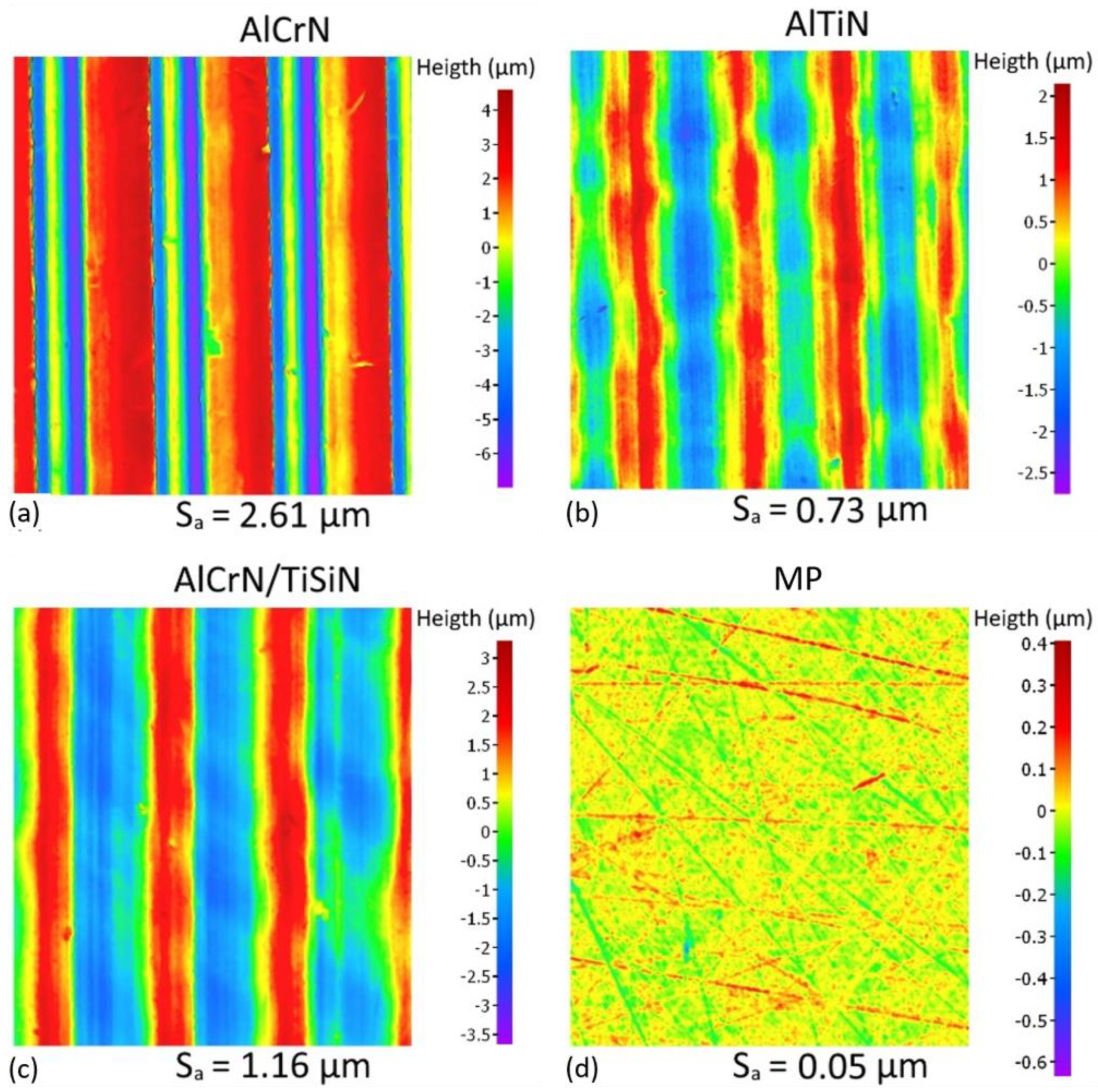
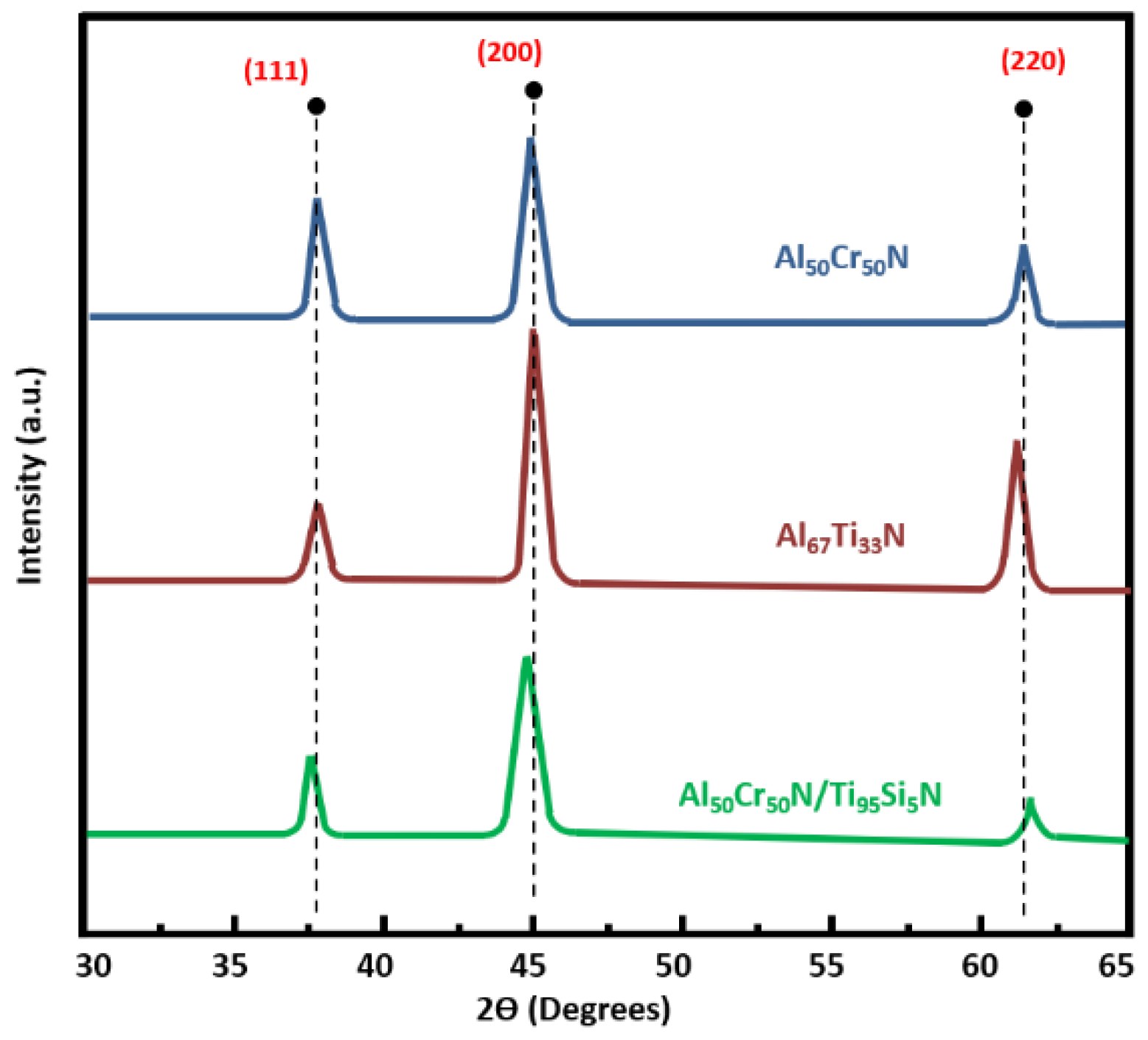
3.1. Machined Surface Characterization

The set of surface roughness maps acquired from the Type 2507 SDSS surface machined with the three PVD-coated inserts is shown in Figure 6 along with the surface roughness map acquired from the MP baseline surface. It is clear from the false colour maps provided for the machined surfaces that the cutting direction was oriented in the vertical direction of the images. The Sa (arithmetical mean height) value associated with each surface is also provided along with the roughness map. As expected, the Sa value associated with the MP baseline surface was the lowest of the set. Of the three PVD-coated inserts, the AlTiN-coated insert produced the smoothest machined surface (lowest Sa value) and the AlCrN-coated insert produced the roughest machined surface.
The feed rate and the tool nose radius were the primary determining components that had a significant impact on surface roughness, as described in [22]. Within the controlled parameters of the study, wherein these factors were maintained at a constant level, the observed divergences in surface textures among the various tested tools necessarily decreased from additional underlying factors. This phenomenon is particularly intriguing when considering Figure 6, which visually underscores substantial variations in groove height across the assessed surfaces. These disparities are effectively visualized through the utilization of a colour scale, which provides a measurable representation of the complex topographical variations.
The multifaceted nature of these variations can be attributed to a multitude of interacting influences, especially when considering different frictional levels associated with distinct tool materials and surface interactions that introduce complex dynamic responses, leading to uneven material removal and ultimately affecting the resulting surface topography. System vibrations, a persistent concern in machining operations, can further amplify these irregularities, introducing oscillatory patterns that intricately shape the machined surface [30]. Additionally, the condition of the tool itself, encompassing parameters like tool wear and cutting-edge geometry, connects with the aforementioned variables to orchestrate the final surface finish [31].
However, it is essential to acknowledge that the scope of these contributing influences is not limited solely to those inherent to the cutting process. Factors extending to the workpiece clamping mechanism and the rigidity of the tool fixture interplay to affect surface finishing outcomes [32]. Moreover, the pervasive occurrence of vibrations during machining procedures, inherent in their dynamic nature, assumes a role of significance. The cumulative effect of these variables leads to an intricate interplay of forces and dynamics, which in turn define the emergent surface texture [33].
An additional level of complexity arises from the ductility of the materials being processed. This is well illustrated by Chen’s findings [23], which establish a correlation between ductility and surface finishing quality. Specifically, materials exhibiting higher ductility tend to exhibit comparatively inferior surface finishes when contrasted with harder, less ductile materials [21,34]. Intriguingly, Chen’s work introduced the notion of an optimal level of flank wear, a concept that unexpectedly suggests that controlled wear may enhance surface finishing attributes. This proposition underscores the intricate balance between wear mechanisms and their ultimate impact on surface integrity [35].
Turning to the analysis of the specific PVD-coated inserts, the acquired surface roughness maps corroborate earlier findings [36], highlighting the pivotal role of coating selection in determining surface quality. The baseline machined surface, machined with the uncoated insert, showcased the lowest Sa value among all tested surfaces, indicating the smoothest finish. Interestingly, the three distinct PVD-coated inserts—AlTiN, AlCrN, and AlCrN/TiSiN—exhibited a discernible spectrum of surface roughness outcomes. Notably, the AlTiN-coated insert emerged as the coated tool that reduced the surface roughness most effectively and yielded a superior machined surface finish, characterized by the lowest Sa value. This outcome aligns with earlier research, where it validates the superior tribological attributes and wear resistance conferred by AlTiN coatings, factors inherently beneficial to enhanced surface quality [6,37,38].
The residual stress state of the SDSS surface was influenced by the type of PVD-coated insert used for machining, as shown in Figure 7. The residual stresses were measured in both the ferrite and austenite phases and in both the cutting and feed directions and compared with the MP baseline surface.
The MP surface showed compressive residual stresses in both phases and directions; these are beneficial for improving the mechanical and corrosion properties of the SDSS components [39]. However, the machined surfaces with PVD-coated inserts showed a combination of tensile and compressive residual stresses, which depend on the phase and direction. The tensile residual stresses are detrimental for the functional performance of the SDSS machined surface, as they can induce cracking, distortion, and stress corrosion [40].
In the cutting direction, all three machined surfaces exhibited tensile residual stresses in both phases; these were caused by the high cutting temperature and plastic deformation during machining. These results are in agreement with a previous analysis [41]. The austenite phase showed a higher sensitivity to the coated insert than the ferrite phase, resulting in different magnitudes of tensile residual stress. The AlCrN/TiSiN-coated insert induced the lowest tensile residual stress in the austenite phase, while the AlTiN-coated insert generated the highest value. This indicates that the AlCrN/TiSiN-coated insert had a better thermal conductivity and wear resistance than the AlTiN-coated insert, which reduced the heat generation and tool–chip friction during machining [6]. Although the value was less than that in the austenite phase, the AlTiN-coated insert likewise generated the highest tensile residual stress in the ferrite phase. This is because the ferrite phase had a lower thermal expansion coefficient and a higher yield strength than the austenite phase, which made it less susceptible to thermal and plastic deformation [42]. Comparable levels of tensile residual stress in the ferrite phase were observed in the other two coated inserts.
Along the feed direction, all three machined surfaces showed compressive residual stresses in both phases, which were generated by the compressive force applied by the tool edge on the workpiece surface during machining [43]. The compressive residual stresses caused elastic-plastic deformation and microstructural changes in the machined layer. The AlTiN-coated insert produced the lowest compressive residual stress in both phases, while the AlCrN/TiSiN-coated insert generated the highest value. This suggests that the AlTiN-coated insert had a lower cutting force and a higher tool wear rate than the AlCrN/TiSiN-coated insert, which decreased the compressive deformation and microhardness of the machined layer.
These interactions affect the mechanical and thermal effects induced by the tool–workpiece contact during machining, which results in plastic deformation and microstructural changes in the machined layer [44]. The residual stress distributions influence the structural integrity and functional performance of the SDSS components, such as fatigue life, wear resistance, and corrosion resistance [45].
Overall, the residual stresses present on a machined surface of a low thermal conductivity alloy are from the tensile nature. The existing differences in the residual stresses among the tested samples are related to the interaction of each coating with the work material during the cutting. The elevated temperature inherent in the cutting process favours the oxidation of the coating and tool substrate. However, the oxidation of the coating elements can generate beneficial oxides that improve the lubricity or protect the tool against heat [46]. Different chemical compositions will result in different oxides, resulting in different effects during the cutting as well as different surface states.
The O and Cr contents of the machined SDSS surfaces are shown in the AES sputter depth profiles in Figure 8. A thin oxide film presented on each surface, as evidenced by the rapid decrease in the O content (Figure 8a) from a peak value at the surface to a negligible value in the first 36 s of sputtering. The oxide film thickness can be assessed by assuming that the midpoint of the O content drop corresponds to the film/metal interface [47]. Based on this assumption, the surface machined with the AlCrN-coated insert had the thickest oxide film, followed by the surfaces machined with the uncoated and AlTiN-coated inserts, respectively. The surface machined with the AlCrN/TiSiN-coated insert had the thinnest oxide film, which suggests that this coating had a better resistance to oxidation than the other coatings.
The Cr content (Figure 8b) represented the composition of the SDSS substrate, as it rose from a minimum value at the surface to a stable value of about 35 at.% after 60 s of sputtering. This value matched the nominal Cr content of the bulk SDSS. The surface machined with the AlCrN-coated insert had a significantly lower initial minimum value of the Cr content than the other surfaces, which suggests that this coating had a higher reactivity with Cr and formed more Cr-rich compounds during machining [48]. This may describe the reason why this coating presented a lower wear resistance and a higher friction coefficient than the other coatings [49].
Overall, the oxide film on the machined SDSS surfaces was determined by the chemical composition, phase distribution, and surface finish of the substrate, as well as by the machining parameters, insert coatings, and environmental conditions [50]. The oxide film was composed of a mixture of chromium oxide (Cr2O3), iron oxide (Fe2O3), and nickel oxide (NiO), with different ratios depending on the oxidation kinetics and the availability of the alloying elements. The oxide film served as a protective layer against corrosion by blocking further oxidation and diffusion of oxygen into the substrate. Nonetheless, excessive thickness, porosity, or unevenness of the oxide deposit could compromise the machined SDSS surface’s mechanical qualities and ability to withstand corrosion.
The thickness and morphology of the oxide film were influenced by the pressure and temperature generated during machining. Higher temperature and pressure may improve the oxidation rate and increase the diffusion of oxygen and alloying elements, leading to thicker and more complex oxide films [51]. Lower temperature and pressure may reduce the oxidation rate and restrict the diffusion of oxygen and alloying elements, leading to thinner and simpler oxide films [51]. The insert coatings may also affect the oxide film formation by altering the tool–workpiece contact area, friction coefficient, heat transfer coefficient, and chemical reactivity [52]. Therefore, different insert coatings may have different impacts on the oxidation behaviour of the machined SDSS surfaces, as was confirmed by the residual stresses’ results. The significant tensile effect generated by the AlTiN-coated tool was revealed by the way it performed during machining. The limited thermal conductivity of the aluminium oxide-based tribofilms formed by the tool, as shown in earlier research, served as a thermal barrier that prohibited heat from accessing the tool [53]. As a result, the heat produced is more probable to be transferred toward the chip and the workpiece. Tensile residual stresses are thus encouraged by the tendency for temperature to rise in the cutting region. The impact of the heat distribution and thermal barrier during a cutting process can be seen in Figure 9.
Finally, the residual stresses present on a machined surface of a low thermal conductivity alloy are from the tensile nature. The existing differences in the residual stresses among the tested samples are related to the interaction of each coating with the work material during the cutting. The elevated temperature inherent in the cutting process favours the oxidation of the coating and tool substrate. However, the oxidation of the coating elements can generate beneficial oxides, which improve the lubricity or protect the tool against heat [46]. Different chemical compositions will result in different oxides, resulting in different effects during the cutting as well as different surface states.

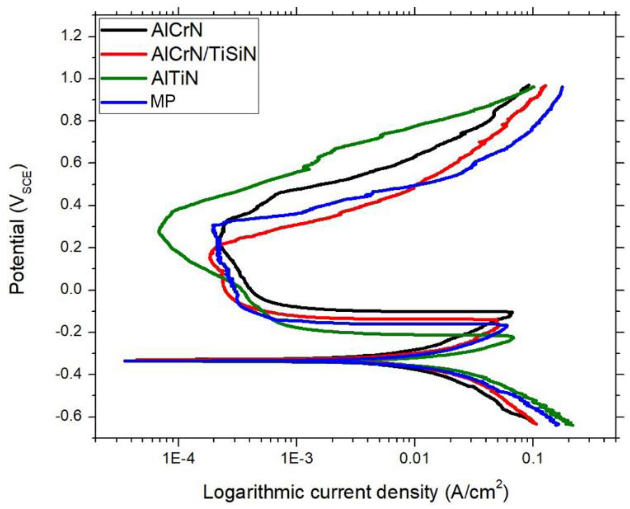
3.2. Electrochemical Measurements

The OCP transients reflect the oxidation and passivation behaviour of the machined stainless-steel surfaces in the electrolyte solution. The oxidation behaviour is influenced by the chemical composition and microstructure of the stainless steel, as well as by the machining conditions and insert coatings. The existence and diffusion of the alloying elements (particularly Cr, Ni, and Mo) control the growth and durability of a protective oxide film on the SDSS surface, which in turn controls the passivation behaviour. Figure 10 shows the OCP transients measured for the three machined surfaces with different coatings and the MP baseline surface. All machined surfaces reached a similar steady-state value of about −0.4 V after approximately 750 s of immersion. The time required to reach this value varies depending on the surface characteristics.
The MP baseline surface and the surface machined with the AlTiN-coated carbide insert had similar OCP transients, which indicate that these surfaces had similar oxidation and passivation characteristics. These surfaces had a stable OCP from the beginning of the immersion, which suggests that they formed a thin and uniform oxide film that prevented further oxidation and corrosion of the substrate [54]. The AlTiN coating had a high hardness and wear resistance, which reduced the tool wear and friction during machining, resulting in a smooth and clean surface finish [55]. The AlTiN coating also had a low affinity for stainless steel, which minimized the adhesion and transfer of the workpiece material to the tool edge, resulting in low contamination of the surface.
On the other hand, the surfaces machined with the AlCrN-coated insert and the AlCrN/TiSiN-coated insert displayed a significantly higher initial OCP than the steady-state value, suggesting a higher thermodynamic tendency for oxidation on these surfaces [56]. A noticeable depassivation transition was observed in both OCP transients, with a longer transition time for the surface machined with the AlCrN-coated insert than for the surface machined with the AlCrN/TiSiN-coated insert. This longer transition time is consistent with the presence of a thicker oxide film on the surface machined with the AlCrN-coated insert, as shown in Figure 8. However, both coatings had a lower hardness and wear resistance than the AlTiN coating, which increased the tool wear and roughness during machining, resulting in a poor surface finish [38].
Potentiodynamic polarization tests, which are frequently employed to assess the passivatability of metals, were utilized to examine the impact of various machining conditions on the electrochemical behaviour of the machined surfaces [57]. Figure 11 shows the polarization curves obtained for the three machined surfaces and the MP baseline surface after a short conditioning period at the OCP (Figure 10). The potential range was −800 mV to +800 mV versus OCP, with a scan rate of 5 mV/s. All curves exhibit similar features, such as an active–passive transition at low anodic overpotentials, a passivation region at intermediate anodic overpotentials, and a stable breakdown of passivity at high anodic overpotentials, which corresponds to the onset of pitting corrosion (Figure 12).
Some electrochemical parameters that were not significantly affected by the machining conditions are the corrosion potential (Ecorr), which represents the equilibrium potential between the anodic and cathodic reactions, the corrosion current density (icorr), which reflects the rate of corrosion in the active state, and the critical anodic current for passivation (icrit), which indicates the minimum current required to form a passive film on the metal surface. These parameters were similar for all machined surfaces and the MP baseline surface, as shown in Table 2. The error values represent one standard deviation of the replicate data set.
However, two parameters that showed noticeable differences among the machined surfaces are the primary passivation potential (Epp) and the breakdown potential (Eb). The potential known as the Eb is where the anodic current suddenly surges because of the localized breakdown of the passive film, and the potential described as the Epp is the point at which the anodic current begins to drop because of the occurrence of a protective oxide layer on the metal’s surface [58]. The Epp and Eb values are listed in Table 2, along with the passivation range, which is defined as Eb—Epp. The passivation range reflects the stability and durability of the passive film [59]. Therefore, a larger passivation range implies a higher resistance to pitting corrosion. Out of the three surfaces that were machined, the AlTiN-coated insert machined surface had the greatest passivation range because both its Epp and Eb were higher than the MP baseline surface. This suggests that this surface had a more stable and protective passive film than the other surfaces. Moreover, this surface also showed a drop in passive current density near Eb, which may indicate a self-healing mechanism of the passive film [60]. The other two machined surfaces had lower Epp and Eb than the MP baseline surface, indicating a lower passivatability and a higher susceptibility to pitting corrosion. These results demonstrate that different machining conditions (in this case different coated tools) can have significant effects on the electrochemical properties of machined surfaces.
Pitting corrosion can reduce the thickness and strength of metal structures and can also act as stress concentrators that can initiate fatigue and stress corrosion cracking, especially in dual-phase steels [61]. Therefore, understanding and preventing pitting corrosion is important for ensuring the integrity and reliability of metal components. In this context, Figure 11 shows the optical micrographs of the MP baseline surface after potentiodynamic polarization tests, which revealed the presence and extent of pitting corrosion. The onset of pitting corrosion can be related to the breakdown potential (Eb) measured from the polarization curves in Figure 10. The breakdown potential is the potential at which the passive film that protects the metal surface from oxidation is locally damaged and not repaired by repassivation [62]. The damage can be caused by various factors, such as chloride ions, oxygen concentration gradients, surface defects, or galvanic coupling with other metals [62].
As shown in Figure 12, the MP baseline surface exhibited a moderate degree of pitting corrosion. This result is consistent with the Eb values shown in Table 2, which show that the AlCrN-coated insert had the highest Eb (300 mV sce), followed by the AlTiN-coated insert and then by the MP baseline surface; the AlCrN/TiSiN represented the lowest Eb. Therefore, it can be concluded that the AlTiN-coated insert had the highest resistance to pitting corrosion among the machined surfaces, while the AlCrN/TiSiN- and AlCrN-coated inserts had the lowest resistance.

3.3. SCC Susceptibility Testing

Figure 13 shows the SEM images of the machined surfaces in plan-view after exposure to boiling MgCl2 (aq) for 2 h, which revealed the occurrence and morphology of stress corrosion cracking (SCC) on each of the three machined surfaces. SCC is a brittle fracture mechanism that results from the combined influence of tensile stress and a corrosive environment [63]. SCC can have different morphologies depending on the material, environment, and stress conditions, such as intergranular, transgranular, or mixed-mode cracking [64].
The surface machined with the AlCrN/TiSiN-coated insert exhibited a branch-like SCC morphology (Figure 13a), which is characterized by random crack branching and propagation without any preferred direction [65]. This morphology suggests that the SCC mechanism was dominated by anodic dissolution of the metal surface, which was enhanced by the presence of chloride ions in the MgCl2 solution. The branch-like SCC morphology on the surface obtained by the AlCrN/TiSiN-coated tool did not show any correlation with the cutting or feed directions, indicating that the machining-induced residual stress and microstructure had little effect on the SCC initiation and growth on this surface.
In contrast, the surfaces machined with the remaining two coated tools (Figure 13b,c) exhibited a stepwise SCC morphology, which is characterized by discrete crack segments that propagate along crystallographic planes or grain boundaries [65]. This morphology suggests that the SCC mechanism was dominated by hydrogen embrittlement of the metal lattice, which was facilitated by the cathodic reaction of water reduction in the MgCl2 solution. The stepwise SCC morphology showed a strong directionality in both the cutting and feed directions, indicating that the machining-induced residual stress and microstructure had a significant effect on the SCC initiation and growth on these surfaces. The residual stress can act as a driving force for crack propagation, while the microstructure can influence the crack path and resistance.
The crack density is an important parameter to evaluate the extent and severity of SCC damage on the machined surfaces [66]. The associated crack densities, as determined using image analysis, are compared in Figure 14. The branched-like cracking exhibited by the surface machined with the AlCrN/TiSiN-coated insert showed a small difference in the crack density when resolved along the two orthogonal directions, with the feed direction having the higher density. In contrast, the stepwise cracking exhibited by the surfaces machined with the remaining two coated inserts showed a significant difference in the crack density when resolved along the two orthogonal directions. In both cases, the cutting direction had the higher density. It is also clear that the surface machined with the AlTiN-coated insert exhibited the highest crack density in both the cutting and feed directions.
The crack density can be influenced by various factors, such as the material properties, the corrosive environment, the applied stress, and the surface quality [67]. In this context, the difference in the crack density along the two orthogonal directions reflects the anisotropy of the SCC behaviour on the machined surfaces, which is related to the machining-induced residual stress and microstructure. The higher crack density in the feed direction for the surface machined with the AlCrN/TiSiN-coated insert indicates that this surface was more susceptible to SCC along the feed direction, which may be due to the higher residual tensile stress or lower microstructural resistance in this direction [11]. The higher crack density in the cutting direction for the surfaces machined with the remaining two coated inserts indicates that these surfaces were more susceptible to SCC along the cutting direction, which may be due to the higher residual tensile stress or lower microstructural resistance in this direction [11]. The highest crack density observed for the surface machined with the AlTiN-coated insert suggests that this surface had the lowest SCC resistance among the three machined surfaces, which may be attributed to its poor surface quality or coating performance.
A set of cross-sectional light optical microscopy images of the SCC exhibited by the machined surfaces is shown in Figure 15: one set each for the plane perpendicular to the cutting and feed directions. The mode of all cracks imaged was transgranular, with propagation occurring through both the ferrite and austenite phases. Despite this, crack initiation tended to be influenced by directionality. Crack initiation occurred in both phases in the plane parallel to the cutting direction, whereas it was restricted to the austenite phase in the plane perpendicular to the cutting direction.
The difference in pitting corrosion resistance among the machined surfaces can be attributed to several factors, such as the surface roughness, residual stress, coating properties, and machining-induced microstructure changes. These factors can affect the formation, stability, and breakdown of the passive film on the metal surface.
It is evident from analysing the residual stress analysis (Figure 7) and the cross-sectional images displayed in Figure 15 that cracks were started in the cutting direction in both phases. The austenitic phase was where the majority of the cracks were located in the feed direction. Figure 15 demonstrates how the cracks spread into the substance through the grains. Due to its increased residual stresses and crack density, the SDSS machined by AlTiN-coated insert exhibited wider cracks. Because of the random propagation of neighbouring cracks, undersurface damage in the cutting direction was visible on the machined cross section when employing the AlCrN/TiSiN-coated insert. Further studies are needed to elucidate the mechanisms and interactions of these factors on pitting corrosion behaviour.
The creation of resistant passive films is primarily due to the alloying elements, in particular Cr [68]; consequently, the Cr content was measured for every machined sample, as presented in Figure 16. An EDS reading at 0.17 min of sputtering was shown because the only variations in the Cr concentration were found close to the surface (time was used for better sputtering control).
Because the surface machined by AlCrN was observed to contain a considerably lower Cr content than AlCrN/TiSiN and AlTiN, it generally experienced delayed passivation. On the other hand, there was no significant difference between the Cr concentration of AlCrN/TiSiN and AlTiN to account for the variations seen in the polarization measurement curves. As the benchmark curve, the SDSS sample was not examined in this case. Differently from Cr, the O content presented considerable differences along the sample depth.

4. Conclusions

Three different PVD coatings were applied on cemented carbide inserts for turning SDSS. Material characterizations such as residual stress, electrochemical and SCC responses, phase, and microstructure of machined SDSS were evaluated in this work. Based on the results achieved the following conclusions can be drawn:
  • Compared to the other evaluated samples, the surface machined with an AlTiN-coated insert has an exceptional corrosion resistance. The AlTiN-coated tool’s capability to prevent surface corrosion is enhanced by early passivation and a broader passive zone, whose behaviour is comparable to that of the polished benchmark sample.
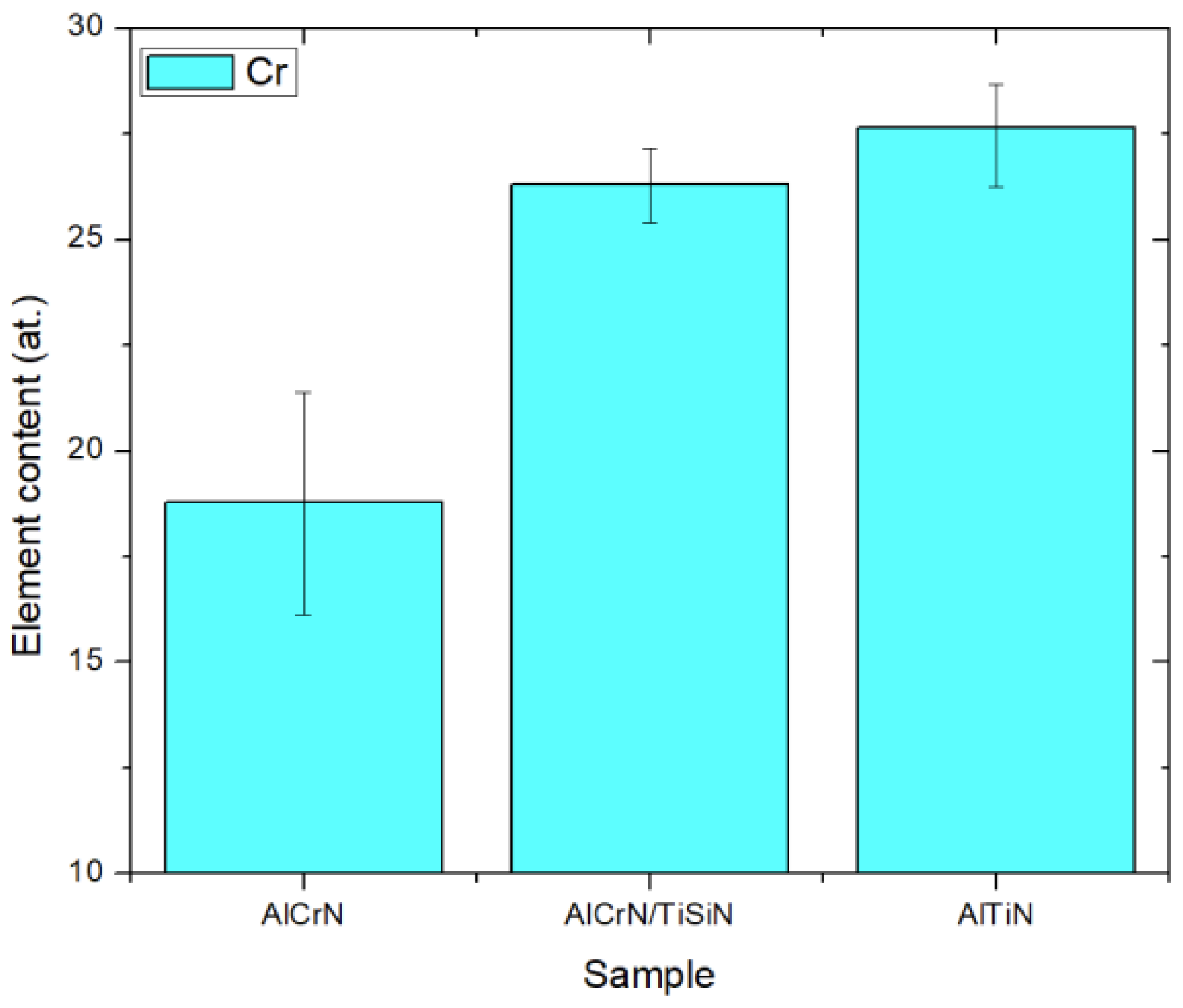
  • Major differences in a surface’s electrochemistry can be attributed to the different Cr contents that each machined surface has. The low Cr content on the surface machined by the AlCrN-coated insert resulted in more corrosion susceptibility when compared to other samples.
  • The oxide thickness present on each machined surface contributes to different potential stabilization times during OCP. The longer transition time is consistent with the presence of a thicker oxide film on the surface machined with the AlCrN-coated insert.
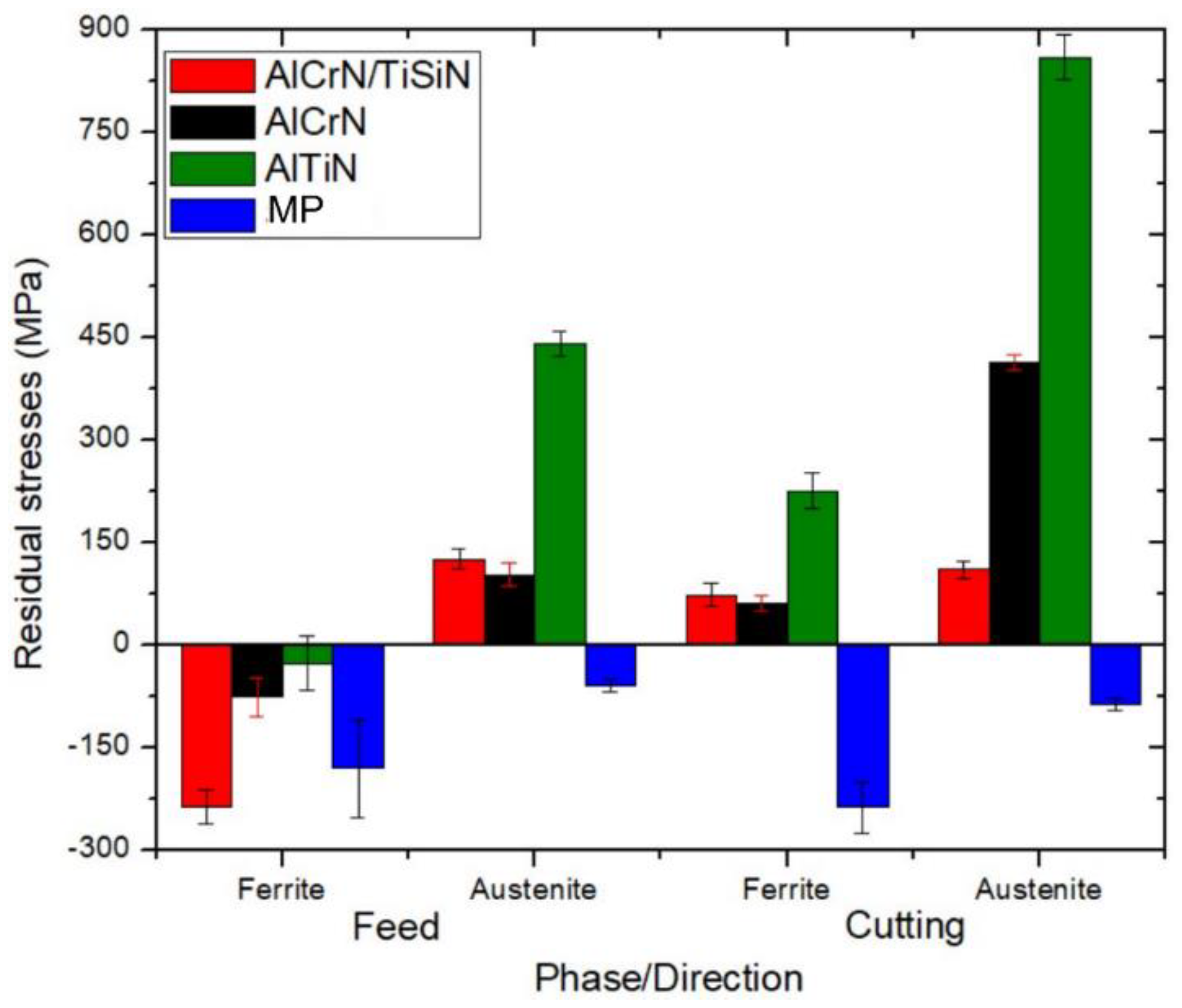
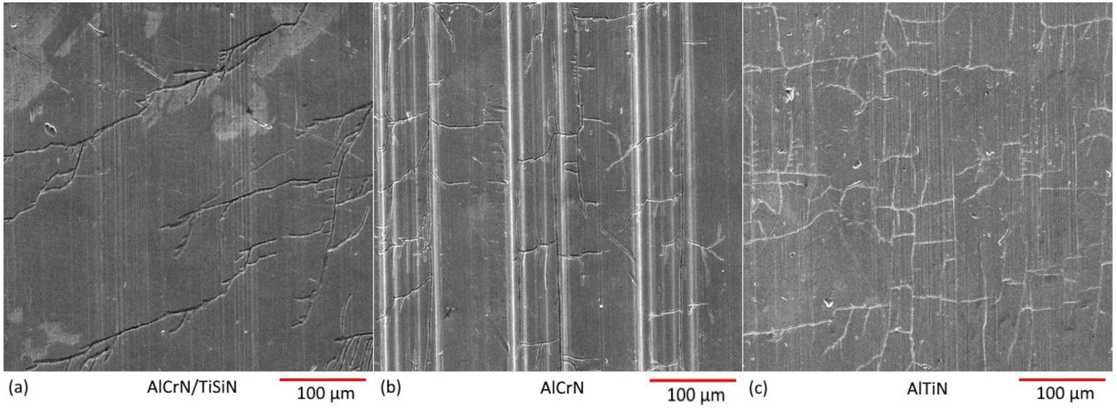
  • SCC response is directly related to the residual stresses generated during the cutting process, where each individual phase can have a different stress state. The SCC susceptibility did not present any relation to the electrochemical behaviour of each sample.
  • In addition to presenting less corrosion susceptibility given by the polarization measurement results, the high tensile nature of AlTiN residual stresses resulted in a high number of cracks in its surface.

Author Contributions

Conceptualization, J.M.D.; Methodology, E.L. and Q.H.; Software, M.G.; Validation, Q.H.; Formal analysis, E.L. and Q.H.; Data curation, A.F.A.; Writing—original draft, J.M.D.; Writing—review & editing, J.M.D. and J.R.K.; Supervision, S.C.V. and J.R.K.; Project administration, M.G.; Funding acquisition, S.C.V. All authors have read and agreed to the published version of the manuscript.

Funding

The authors received financial support from the Natural Sciences and Engineering Research Council of Canada (NSERC) under the Canadian Network for Research and Innovation in Machining Technology (Grant number—NSERC NETGP 479639-15).

Data Availability Statement

No new data were created or analyzed in this study. Data sharing is not applicable to this article.

Conflicts of Interest

The authors declare no conflict of interest.

References

  1. Tan, H.; Jiang, Y.; Deng, B.; Sun, T.; Xu, J.; Li, J. Effect of annealing temperature on the pitting corrosion resistance of super duplex stainless steel UNS S32750. Mater. Charact. 2009, 60, 1049–1054. [Google Scholar] [CrossRef]
  2. Pardal, J.M.; Tavares, S.S.M.; Fonseca, M.C.; de Souza, J.A.; Côrte, R.R.A.; de Abreu, H.F.G. Influence of the grain size on deleterious phase precipitation in superduplex stainless steel UNS S32750. Mater. Charact. 2009, 60, 165–172. [Google Scholar] [CrossRef]
  3. Cvijović, Z.; Radenković, G. Microstructure and pitting corrosion resistance of annealed duplex stainless steel. Corros. Sci. 2006, 48, 3887–3906. [Google Scholar] [CrossRef]
  4. Pohl, M.; Storz, O.; Glogowski, T. Effect of intermetallic precipitations on the properties of duplex stainless steel. Mater. Charact. 2007, 58, 65–71. [Google Scholar] [CrossRef]
  5. Smiderle, J.; Pardal, J.M.; Tavares, S.S.M.; Vidal, A.C.N. Premature failure of superduplex stainless steel pipe by pitting in sea water environment. Eng. Fail. Anal. 2014, 46, 134–139. [Google Scholar] [CrossRef]
  6. de Paiva, J.M.F.; Torres, R.D.; Amorim, F.L.; Covelli, D.; Tauhiduzzaman, M.; Veldhuis, S.; Dosbaeva, G.; Fox-Rabinovich, G. Frictional and wear performance of hard coatings during machining of superduplex stainless steel. Int. J. Adv. Manuf. Technol. 2017, 92, 423–432. [Google Scholar] [CrossRef]
  7. Fernández-Abia, A.I.; Barreiro, J.; Fernández-Larrinoa, J.; de Lacalle, L.N.L.; Fernández-Valdivielso, A.; Pereira, O.M. Behaviour of PVD Coatings in the Turning of Austenitic Stainless Steels. Procedia Eng. 2013, 63, 133–141. [Google Scholar] [CrossRef]
  8. Paiva, J.M.F.; Amorim, F.L.; Soares, P.C.; Veldhuis, S.C.; Mendes, L.A.; Torres, R.D. Tribological behavior of superduplex stainless steel against PVD hard coatings on cemented carbide. Int. J. Adv. Manuf. Technol. 2017, 90, 1649–1658. [Google Scholar] [CrossRef]
  9. Navas, V.G.; Gonzalo, O.; Bengoetxea, I. Effect of cutting parameters in the surface residual stresses generated by turning in AISI 4340 steel. Int. J. Mach. Tools Manuf. 2012, 61, 48–57. [Google Scholar] [CrossRef]
  10. Nilsson, J.-O. Super duplex stainless steels. Mater. Sci. Technol. 1992, 8, 685–700. [Google Scholar] [CrossRef]
  11. Rajaguru, J.; Arunachalam, N. Investigation on machining induced surface and subsurface modifications on the stress corrosion crack growth behaviour of super duplex stainless steel. Corros. Sci. 2018, 141, 230–242. [Google Scholar] [CrossRef]
  12. Topolska, S.; Łabanowski, J. Effect of microstructure on impact toughness of duplex and superduplex stainless steels. J. Achiev. Mater. Manuf. Eng. 2009, 36, 142–149. [Google Scholar]
  13. Cui, J.; Park, I.-S.; Kang, C.-Y.; Miyahara, K. Degradation of Impact Toughness due to Formation of R Phase in High Nitrogen 25Cr-7Ni-Mo Duplex Stainless Steels. ISIJ Int. 2001, 41, 192–195. [Google Scholar] [CrossRef]
  14. Bastos, I.N.; Tavares, S.S.M.; Dalard, F.; Nogueira, R.P. Effect of microstructure on corrosion behavior of superduplex stainless steel at critical environment conditions. Scr. Mater. 2007, 57, 913–916. [Google Scholar] [CrossRef]
  15. Zhang, Z.; Jing, H.; Xu, L.; Han, Y.; Zhao, L.; Zhang, J. Influence of microstructure and elemental partitioning on pitting corrosion resistance of duplex stainless steel welding joints. Appl. Surf. Sci. 2017, 394, 297–314. [Google Scholar] [CrossRef]
  16. Tavares, S.S.M.; Pardal, J.M.; Lima, L.D.; Bastos, I.N.; Nascimento, A.M.; de Souza, J.A. Characterization of microstructure, chemical composition, corrosion resistance and toughness of a multipass weld joint of superduplex stainless steel UNS S32750. Mater. Charact. 2007, 58, 610–616. [Google Scholar] [CrossRef]
  17. Nowacki, J.; Łukojc, A. Microstructural transformations of heat affected zones in duplex steel welded joints. Mater. Charact. 2006, 56, 436–441. [Google Scholar] [CrossRef]
  18. Tavares, S.S.M.; Silva, V.G.; Pardal, J.M.; Corte, J.S. Investigation of stress corrosion cracks in a UNS S32750 superduplex stainless steel. Eng. Fail. Anal. 2013, 35, 88–94. [Google Scholar] [CrossRef]
  19. Krolczyk, G.; Gajek, M.; Legutko, S. Effect of the cutting parameters impact on tool life in duplex stainless steel turning process. Teh. Vjesn. 2013, 20, 587–592. [Google Scholar]
  20. Bordinassi, E.; Filho, M.; Batalha, G.; Delijaicov, S.; Lima, N. Superficial integrity analysis in a super duplex stainless steel after turning. J. Achiev. Mater. Manuf. Eng. 2006, 18, 335–338. [Google Scholar]
  21. de Oliveira Junior, C.A.; Diniz, A.E.; Bertazzoli, R. Correlating tool wear, surface roughness and corrosion resistance in the turning process of super duplex stainless steel. J. Braz. Soc. Mech. Sci. Eng. 2014, 36, 775–785. [Google Scholar] [CrossRef]
  22. Shaw, M. Metal Cutting Principles, 2nd ed.; Oxford Unversity Press: New York, NY, USA, 2005. [Google Scholar]
  23. Chen, W. Cutting forces and surface finish when machining medium hardness steel using CBN tools. Int. J. Mach. Tools Manuf. 2000, 40, 455–466. [Google Scholar] [CrossRef]
  24. Stephenson, D.A.; Agapiou, J.S. Metal Cutting Theory and Practice; CRC Press: Boca Raton, FL, USA, 2016. [Google Scholar]
  25. Vetter, J.; Eriksson, A.O.; Reiter, A.; Derflinger, V.; Kalss, W. Quo Vadis: AlCr-Based Coatings in Industrial Applications. Coatings 2021, 11, 344. [Google Scholar] [CrossRef]
  26. Pereira, C.B.G.; He, Q.; Soares, P.; Meruvia, M.S.; de Souza, G.B.; Amorim, F.L.; De Paiva, J.M.; Veldhuis, S.C.; Torres, R.D. Tribological characterization of PVD TiSiN/AlCrN coating: A comprehensive study on thermal effect. Mater. Charact. 2023, 203, 113135. [Google Scholar] [CrossRef]
  27. He, Q.; Paiva, J.M.; Kohlscheen, J.; Beake, B.D.; Veldhuis, S.C. Study of wear performance and tribological characterization of AlTiN PVD coatings with different Al/Ti ratios during ultra-high speed turning of stainless steel 304. Int. J. Refract. Metals Hard Mater. 2021, 96, 105488. [Google Scholar] [CrossRef]
  28. Chen, W.; Yan, A.; Wang, C.; Deng, Y.; Chen, D.C.; Xiao, H.; Zhang, D.; Meng, X. Microstructures and mechanical properties of AlCrN/TiSiN nanomultilayer coatings consisting of fcc single-phase solid solution. Appl. Surf. Sci. 2020, 509, 145303. [Google Scholar] [CrossRef]
  29. ASTM G36; Standard Practice for Evaluating Stress-Corrosion-Cracking Resistance of Metals and Alloys in a Boiling Magnesium Chloride Solution. ASTM: West Conshohocken, PA, USA, 2018.
  30. Grzesik, W.; Ruszaj, A. Vibration-Assisted Machining Processes BT—Hybrid Manufacturing Processes: Physical Fundamentals, Modelling and Rational Applications; Grzesik, W., Ruszaj, A., Eds.; Springer International Publishing: Cham, Switzerland, 2021; pp. 81–104. [Google Scholar] [CrossRef]
  31. Filho, T.K.; He, Q.; Paiva, J.M.; Veldhuis, S.C. An analysis of different cutting strategies to improve tool life when machining Ti-5Al-5V-5Mo-3Cr alloy. J. Manuf. Process. 2023, 102, 50–66. [Google Scholar] [CrossRef]
  32. Qi, R.; Mao, X.; Zhang, K.; Xia, R. Accurate Clamping Method of Multipoint Flexible Fixture for Large Complex Surface. Math. Probl. Eng. 2021, 2021, 5568801. [Google Scholar] [CrossRef]
  33. Sun, W.; Luo, M.; Zhang, D. Machining vibration monitoring based on dynamic clamping force measuring in thin-walled components milling. Int. J. Adv. Manuf. Technol. 2020, 107, 2211–2226. [Google Scholar] [CrossRef]
  34. Thamizhmanii, S.; Hasan, S. Investigation of Surface Roughness and Flank Wear by CBN and PCBN Tools on Hard Cr-Mo Steel. J. Achiev. Mater. Manuf. Eng. 2008, 31, 415–421. [Google Scholar]
  35. Denape, J. Wear Mechanisms. In Tribology of Ceramics and Composites; John Wiley & Sons, Ltd.: Hoboken, NJ, USA, 2011. [Google Scholar] [CrossRef]
  36. Mazid, A.M.; Imam, T.; Ahsan, K.B.; Khandoker, N. Characterising surface roughness of Ti-6Al-4V alloy machined using coated and uncoated carbide tools with variable nose radius by machine learning. Eng. Appl. Artif. Intell. 2023, 124, 106546. [Google Scholar] [CrossRef]
  37. Khoei, A.A.; He, Q.; DePaiva, J.M.; Bose, B.; Veldhuis, S.C. Assessment of the tribological and wear performance of new duplex AlTiN-based coating systems at high temperatures when threading super duplex stainless steel. J. Manuf. Process. 2023, 98, 285–301. [Google Scholar] [CrossRef]
  38. He, Q.; DePaiva, J.M.; Kohlscheen, J.; Veldhuis, S.C. Analysis of the performance of PVD AlTiN coating with five different Al/Ti ratios during the high-speed turning of stainless steel 304 under dry and wet cooling conditions. Wear 2022, 492–493, 204213. [Google Scholar] [CrossRef]
  39. Deshpande, N.C.; Vasudevan, H. A Model for Residual Stress in the Dry Turning of Duplex Stainless Steels. Key Eng. Mater. 2022, 933, 25–31. [Google Scholar] [CrossRef]
  40. Simon, N.; Erdle, H.; Walzer, S.; Gibmeier, J.; Böhlke, T.; Liewald, M. Residual stresses in deep-drawn cups made of duplex stainless steel X2CrNiN23-4. Forsch. Im Ingenieurwesen 2021, 85, 795–806. [Google Scholar] [CrossRef]
  41. Payares-Asprino, C.; de Escalona, P.M.; Sanchez, A. Residual stress in machined duplex stainless steel welds developed through automatic process. In Proceedings of the IV International Conference on Welding and Joining of Materials—ICONWELD 2018, San Miguel, Peru, 6–8 August 2018; Pontificia Universidad Católica del Perú: San Miguel, Peru, 2019; pp. 222–230. [Google Scholar]
  42. Santos, C.E.D.; Carneiro, J.R.G.; da Silva, G.C.; Brito, P.P.; Santos, Í.B.D.; Campos, T.R. Residual stress and surface microhardness post-milling in 2205 duplex steel. Int. J. Adv. Manuf. Technol. 2021, 113, 3445–3455. [Google Scholar] [CrossRef]
  43. Wan, M.; Ye, X.-Y.; Wen, D.-Y.; Zhang, W.H. Modeling of machining-induced residual stresses. J. Mater. Sci. 2019, 54, 1–35. [Google Scholar] [CrossRef]
  44. Wang, F.; Mao, K.; Ying, H.; Zhu, Y.; Yin, L. Equivalent parameters-based residual thermal stress fields modeling and design for square coated indexable cutting inserts. Int. J. Adv. Manuf. Technol. 2019, 102, 567–581. [Google Scholar] [CrossRef]
  45. Cheng, Y.; Xu, M.; Guan, R.; Liu, L.; Qian, J. Generation mechanism of insert residual stress while cutting 508III steel. Int. J. Adv. Manuf. Technol. 2017, 91, 247–255. [Google Scholar] [CrossRef]
  46. Fox-Rabinovich, G.; Totten, G.E. Self-Organization During Friction—Advanced Surface-Engineered Materials and Systems Design, 1st ed.; CRC Press: Boca Raton, FL, USA, 2006. [Google Scholar]
  47. Ajo, H.; Blankenship, D.; Clark, E. Analysis of Passivated A-286 Stainless Steel Surfaces for Mass Spectrometer Inlet Systems by Auger Electron and X-ray Photoelectron Spectroscopy and Scanning Electron Microscopy. Metallogr. Microstruct. Anal. 2014, 3, 263–271. [Google Scholar] [CrossRef]
  48. Rar, A.; Hofmann, S.; Yoshihara, K.; Kajiwara, K. Optimization of depth resolution parameters in AES sputter profiling of GaAs/AlAs multilayer structures. Appl. Surf. Sci. 1999, 144–145, 310–314. [Google Scholar] [CrossRef]
  49. Kerber, S.J.; Tverberg, J. Stainless steel surface analysis: AES and XPS analysis of the passivation layer on stainless steel can help determine how well it will resist corrosion. Adv. Mater. Process. 2000, 158, 33–36. [Google Scholar]
  50. Dikusar, A.I.; Silkin, S.A. Formation and Breakdown of Oxide Films in High-Rate Anodic Dissolution of Chromium–Nickel Steels in Electrolytes for Electrochemical Machining. Surf. Eng. Appl. Electrochem. 2022, 58, 313–322. [Google Scholar] [CrossRef]
  51. Yuan, J.; Fox-Rabinovich, G.S.; Veldhuis, S.C. Control of tribofilm formation in dry machining of hardened AISI D2 steel by tuning the cutting speed. Wear 2018, 402–403, 30–37. [Google Scholar] [CrossRef]
  52. Chen, W.; Wu, W.; Huang, Y.; Wu, D.; Li, B.; Wang, C.; Wang, Y.; Li, S. Influence of annealing on microstructures and mechanical properties of arc-deposited AlCrTiSiN coating. Surf. Coat. Technol. 2021, 421, 127470. [Google Scholar] [CrossRef]
  53. Liang, X.; Liu, Z.; Wang, B.; Wang, C.; Cheung, C.F. Friction behaviors in the metal cutting process: State of the art and future perspectives. Int. J. Extrem. Manuf. 2022, 5, 12002. [Google Scholar] [CrossRef]
  54. Wang, J.; Liu, H.; Kijkla, P.; Kumseranee, S.; Punpruk, S.; Mohamed, M.E.-S.; Saleh, M.A.; Gu, T. Comparison of 304 SS, 2205 SS, and 410 SS Corrosion by Sulfate-Reducing Desulfovibrio ferrophilus. J. Chem. 2021, 2021, 3268404. [Google Scholar] [CrossRef]
  55. Philip, A.M.; Chakraborty, K. Some studies on the machining behaviour of 316L austenitic stainless steel. Mater. Today Proc. 2022, 56, 681–685. [Google Scholar] [CrossRef]
  56. Becker, H.; Dickinson, E.J.F.; Lu, X.; Bexell, U.; Proch, S.; Moffatt, C.; Stenström, M.; Smith, G.; Hinds, G. Assessing potential profiles in water electrolysers to minimise titanium use. Energy Environ. Sci. 2022, 15, 2508–2518. [Google Scholar] [CrossRef]
  57. Hassan, H.M.; Attia, A.A.; Zordok, W.A.; Eldesoky, A.M. Potentiodynamic polarization, Electrochemical Impedance Spectroscopy (EIS) and Density functional theory studies of Sulfa Guanidine Azomethine as Efficient Corrosion Inhibitors for Nickel Surface in hydrochloeic acid solution. Int. J. Sci. Eng. Res. 2014, 5, 369–380. [Google Scholar]
  58. Zhou, L.; Zhao, Q.; Lv, G.; Dou, Z.; Mu, W.; Zhang, T. Effect of NH4Cl on the rusting leaching behavior of metallic phase of iron in reduced ilmenite during TiO2 purification: An electrochemical and density-functional theory study. Appl. Surf. Sci. 2023, 638, 158019. [Google Scholar] [CrossRef]
  59. Hassel, T.; Maier, H.J.; Alkhimenko, A.; Davydov, A.; Shaposhnikov, N.; Turichin, G.; Klimova, O. Investigation of the mechanical properties and corrosion behaviour of hybrid L 80 Type 1 and duplex steel joints produced by magnetically impelled arc butt welding. J. Adv. Join. Process. 2022, 5, 100109. [Google Scholar] [CrossRef]
  60. Wang, L.; Ding, Y.; Lu, Q.; Guo, Z.; Liu, Y.; Cui, Z. Microstructure and corrosion behavior of welded joints between 2507 super duplex stainless steel and E690 low alloy steel. Corros. Commun. 2023, 11, 1–11. [Google Scholar] [CrossRef]
  61. Sung, C.; Shin, B.-H.; Chung, W. Effect of Solution Annealing on Austenite Morphology and Pitting Corrosion of Super Duplex Stainless Steel UNS S 32750. Int. J. Electrochem. Sci. 2021, 16, 210813. [Google Scholar] [CrossRef]
  62. Kim, J.-H.; Choi, S.-W.; Park, D.-H.; Lee, J.-M. Charpy impact properties of stainless steel weldment in liquefied natural gas pipelines: Effect of low temperatures. Mater. Des. (1980–2015) 2015, 65, 914–922. [Google Scholar] [CrossRef]
  63. Rajaguru, J.; Arunachalam, N. A comprehensive investigation on the effect of flood and MQL coolant on the machinability and stress corrosion cracking of super duplex stainless steel. J. Mater. Process. Technol. 2020, 276, 116417. [Google Scholar] [CrossRef]
  64. Sharma, L.; Sharma, K. Dissimilar welding of super duplex stainless steel (SDSS) and pipeline steel—A brief overview. Mater. Today Proc. 2022, in press. [Google Scholar] [CrossRef]
  65. George, P.; Wins, K.L.D.; Dhas, D.S.E.J.; George, P.; Beatrice, B.A. Machinability, weldability and surface treatment studies of SDSS 2507 material—A review. Mater. Today Proc. 2021, 46, 7682–7687. [Google Scholar] [CrossRef]
  66. Wickström, L.; Mingard, K.; Hinds, G.; Turnbull, A. Microcrack clustering in stress corrosion cracking of 22Cr and 25Cr duplex stainless steels. Corros. Sci. 2016, 109, 86–93. [Google Scholar] [CrossRef]
  67. Pereira, H.B.; Azevedo, C.R.F. Can the drop evaporation test evaluate the stress corrosion cracking susceptibility of the welded joints of duplex and super duplex stainless steels? Eng. Fail. Anal. 2019, 99, 235–247. [Google Scholar] [CrossRef]
  68. Jones, D.A. Principles and Prevention of Corrosion, 2nd ed.; Prentice Hall: Upper Saddle River, NJ, USA, 1996. [Google Scholar]
Figure 1. Light optical micrograph image showing the cross-sectional microstructure of the Type 2507 SDSS tube product used in this study.
Coatings 14 00290 g001
Figure 2. Coating scheme for commercial deposition.
Coatings 14 00290 g002
Figure 3. XRD phase identification of three coatings.
Coatings 14 00290 g003
Figure 4. Scheme of sample preparation for material measurements.
Coatings 14 00290 g004
Figure 5. Digital image of the machined surface produced using the AlCrN-coated cemented carbide tool insert showing the typical appearance of the machining groves.
Coatings 14 00290 g005
Figure 6. Surface roughness maps acquired from the machined surfaces produced using: (a) AlCrN-coated insert, (b) AlTiN-coated insert, (c) AlCrN/TiSiN-coated insert, and (d) MP baseline surface.
Coatings 14 00290 g006
Figure 7. Residual stress measurements acquired from the machined surfaces. Data are presented for the ferrite and austenite phases in each orthogonal direction (cutting and feed directions).
Coatings 14 00290 g007
Figure 8. (a,b) AES sputter (depth) profiles acquired from the machined surfaces.
Coatings 14 00290 g008
Figure 9. Thermal barrier and heat distribution in a cutting process.
Coatings 14 00290 g009
Figure 10. Typical OCP transients of the machined surfaces recorded immediately after immersion in the 1 M NaCl (aq) + 1 M H2SO4 (aq) electrolyte at 90 °C.
Coatings 14 00290 g010
Figure 11. Typical potentiodynamic polarization curves of the machined surfaces recorded after the OCP conditioning shown in Figure 10.
Coatings 14 00290 g011
Figure 12. Pitting corrosion on mechanically polished (MP) SDSS.
Coatings 14 00290 g012
Figure 13. Plan-view SEM images of the machined surfaces after exposure to boiling MgCl2 (aq) for 2 h: (a) the AlCrN/TiSiN-coated insert, (b) the AlCrN-coated insert, and (c) the AlTiN-coated insert.
Coatings 14 00290 g013
Figure 14. Directionally resolved crack density values of the SCC exhibited by the machined surfaces after exposure to boiling MgCl2 (aq) for 2 h.
Coatings 14 00290 g014
Figure 15. Planar-resolved cross-sectional light optical microscopy images of the SCC exhibited by the machined surfaces after exposure to boiling MgCl2 (aq) for 2 h: (a,d) the AlCrN/TiSiN-coated insert, (b,e) the AlCrN-coated insert, and (c,f) the AlTiN-coated insert. The ellipses are showing the cracks on the surface.
Coatings 14 00290 g015
Figure 16. Cr content (at.%) on three machined samples’ surfaces.
Coatings 14 00290 g016
Table 1. Tube product.
CrNiMoMnCuSiWNCFe
25.07.14.01.10.80.70.60.30.03Bal.
Table 2. Comparison of the electrochemical kinetic parameters.
Machined SurfaceEcorr (mVSCE)Epp (mVSCE)Eb (mVSCE)Passivation Range
AlCrN−334 ± 16−70 ± 3+300 ± 15370 mV
AlCrN/TiSiN−324 ± 16−139 ± 7+137 ± 7276 mV
AlTiN−331 ± 16−214 ± 10+256 ± 13470 mV
MP (Baseline)−329 ± 16−161 ± 8+247 ± 12408 mV
Disclaimer/Publisher’s Note: The statements, opinions and data contained in all publications are solely those of the individual author(s) and contributor(s) and not of MDPI and/or the editor(s). MDPI and/or the editor(s) disclaim responsibility for any injury to people or property resulting from any ideas, methods, instructions or products referred to in the content.

