Article

Experimental and Simulation Studies on Thermal Shock of Multilayer Thermal Barrier Coatings with an Intermediate Transition Layer at 1500 °C

1
Key Laboratory of Pressure System and Safety, Ministry of Education, East China University of Science and Technology, Shanghai 200237, China
2
Shanghai Institute of Aircraft Mechanics and Control, Shanghai 200092, China
*
Authors to whom correspondence should be addressed.
These authors contributed equally to this work.
Coatings 2024, 14(12), 1614; https://doi.org/10.3390/coatings14121614
Submission received: 14 November 2024 / Revised: 19 December 2024 / Accepted: 21 December 2024 / Published: 23 December 2024

Abstract

:
Strain tolerance is a crucial factor affecting the thermal life of coatings, and a higher strain tolerance can effectively alleviate the thermal stresses on coatings during thermal shock. To improve the strain tolerance, the coating structure was optimized by introducing an intermediate transition layer in this study. The intermediate transition layer material was prepared using a 1:1 volume ratio mixture of 6–8 wt. % Yttria-stabilized zirconia (YSZ) and NiCrAlY powders in the experiments. The coating structure consisted of an Al2O3-GdAlO3 (AGAP) anti-erosion layer, a YSZ layer, an intermediate transition layer, and a bonding layer from top to bottom. After thermal shock experiments at 1500 °C, the coatings with the addition of the intermediate transition layer exhibited different failure modes, with the crack location shifting from between the YSZ and the bonding layer to within the intermediate transition layer, compared to the coatings without the intermediate transition layer. Finite element simulation analysis showed that the intermediate transition layer effectively increased the strain tolerance of the coating and significantly reduced the thermal stress. Furthermore, incorporating an embedded micron agglomerated particle-based (EMAP) thermal barrier coating structure into the intermediate transition layer effectively alleviated thermal stresses and enhanced the coating’s thermal insulation performance.

1. Introduction

Thermal barrier coatings (TBCs) are widely used in the hot-end components of aircraft engines to provide adequate thermal protection and insulation [1,2,3,4]. TBCs can increase the operating temperature of engines, resulting in significant improvements in engine efficiency and performance. Typical TBC systems consist of a super-alloy substrate, a metallic bond coat (BC) layer (MCrAlY, M = Ni or/and Co), and a ceramic topcoat (TC) layer [5,6]. In general, TBCs are deposited by atmospheric plasma spraying (APS) and have lamellar microstructures. Among them, MCrAlY (M = Ni or/and Co) is widely used for the metal bonding layer material; its primary function is to relieve the interfacial stresses and to improve the compatibility of the thermal expansion between the TC layer and the substrate. The TC layer, on the other hand, is mainly responsible for thermal insulation and possesses high heat resistance and low thermal conductivity [7,8]. In addition, considering the harsh environment in which the high-temperature alloys are exposed, the material for the TC layer also needs to have good corrosion resistance to ensure long-term stability. Among the known materials, 6–8 (wt. %) Yttria-stabilized zirconia (YSZ) is the most widely used ceramic layer material [9]. This is due to it exhibiting high toughness, heat resistance, strength, a coefficient of thermal expansion, and low cost. However, the working temperature of YSZ coatings should not exceed 1200 °C for long periods of time. Otherwise, sintering will occur in the coating, leading to microstructural changes such as grain growth and reduced porosity. For YSZ, high-temperature sintering can trigger phase transitions, particularly from the stable cubic phase to the monoclinic phase. This phase change is often accompanied by volume expansion, which increases internal stresses and can result in crack formation and delamination. These microstructural changes significantly degrade the thermal performance and structural integrity of the coating, thereby reducing its thermal lifespan [10,11]. With the rapid development of advanced gas turbine technology, the requirements for the engine operating temperature continue to increase, and the working environment faced by the thermal barrier coatings becomes more and more severe. Therefore, it is essential to find ways to increase the service temperature of thermal barrier coatings [12,13,14].
Plasma-sprayed coatings are formed by the continuous stacking of solidified flakes, and they show a layered structure because the interfaces of the flakes are not fully bonded, leading to a large number of two-dimensional inter-plate pores between the flakes [15,16,17,18,19,20]. Many practices and research results show that the cracking failure of thermal barrier coatings prepared by APS technology is mainly related to the following three aspects [21,22,23,24,25,26]: (1) The characteristic laminated microstructure of APS coatings generates a large number of parallel microcracks inside the coatings. These microcracks reduce the bonding strength between the coating and the metal substrate as well as the cracking resistance of the coating itself, which can easily lead to coating spalling under thermal shock conditions [21,22]. (2) Under thermal shock conditions, thermal stresses are generated inside the coating due to the difference in thermal expansion coefficients of the TC layer and the metal substrate. Meanwhile, microcracks inside the coating will continue to propagate and expand under the effect of thermal shock stress, finally leading to the spalling failure of the coating [23,24]. Furthermore, the sintering of the coating in a high-temperature environment leads to an increase in its stiffness and a decrease in its strain tolerance, which also increases the thermal stresses due to thermal expansion mismatch. (3) Thermal growth oxides (TGOs) formed by oxidation of thermal barrier coatings at high temperatures are also one of the essential causes of coating spallation failure [25,26].
APS-prepared coatings with excellent fracture toughness and strain tolerance can significantly improve the thermal shock life of the coatings [27]. However, due to the loose and porous layered microstructure of APS thermal barrier coatings, the fracture toughness and strain tolerance of the coatings usually show an inverted relationship, making it difficult to achieve the advantages of high strain tolerance and high fracture toughness at the same time [28,29]. For example, in our previous studies [30,31], it was found that the Al2O3-GdAlO3-YSZ (AGAP-YSZ) coating system demonstrates superior fracture toughness, while the AGAP-Gd2Zr2O7-YSZ (AGAP-GZ-YSZ) coating system exhibits higher strain tolerance. Furthermore, the failure modes of the AGAP-YSZ coating system and the AGAP-GZ-YSZ coating system were completely different under the thermal shock experimental conditions at 1500 °C. The failure of the AGAP-YSZ coating system was mainly due to the excessive thermal stress, which led to interfacial cracking. In contrast, no significant cracking was observed inside the YSZ layer. In contrast, the AGAP-GZ-YSZ system, although with lower internal thermal stress, is prone to crack sprouting and expansion within the GZ layer during thermal shock due to the lower fracture toughness of the GZ layer, which leads to the premature failure of the coating. Overall, the AGAP-YSZ coating system exhibits good fracture toughness. However, cracking occurs due to excessive interfacial thermal stress during thermal shock, while the AGAP-GZ-YSZ system, although with lower thermal stress, leads to premature coating failure due to insufficient fracture toughness of the GZ layer. To achieve a coating system with higher thermal shock life, a coating with good fracture toughness and low thermal stress is needed. To provide excellent fracture toughness of AGAP-YSZ coatings, this study suggests the introduction of an intermediate transition layer in the AGAP-YSZ coating system. Through the intermediate transition layer, it may improve the strain tolerance of the coating system, relieve the thermal stresses inside the coating, and further improve the thermal shock life of the coating. For simplicity, the AGAP-YSZ coating system is denoted as the AGAP-YSZ-BC Layer (AYB) coating, while the AGAP-YSZ-Intermediate Layer coating system is referred to as the AGAP-YSZ-Intermediate Layer-BC Layer (AYIB) coating in this paper. Additionally, a novel embedded micron agglomerated particle-based (EMAP) thermal barrier coating, known as the EMAP coating, with high thermal shock resistance was developed by our group in previous research [32]. The novel structured coating is prepared by controllably embedding a second-phase powder particle with a specific pore structure into the coating matrix formed by conventional spraying during the plasma spraying process to prepare a composite thermal barrier coating with a dense conventional coating matrix and a dispersion of structurally specific secondary phase particles therein. The second-phase particles with specific pore structures are called porous embedded particle clusters (PEPC) [32,33]. The advantage of EMAP coatings over conventional coatings is that the dense coating matrix ensures high fracture toughness of the coating as a whole. The coating’s strain tolerance and thermal insulation capacity can be improved by modulating the pore structure of the coating through the second-phase powder particles.
In the experiments conducted in this study, three different spray coating processes for the intermediate transition layer were designed to investigate their impact on the performance of traditional thermal barrier coatings. These processes were labeled as Group A, Group B, and Group C. In these three groups, the spraying parameters of the AGAP layer, YSZ layer, and BC layer were kept consistent. Among them, the spraying parameters of the intermediate transition layer for the coatings in Groups A and C were consistent with those of the BC and YSZ layers, respectively. In contrast, the spraying process parameters of the intermediate transition layer for the coatings in Group B were taken to be the middle value between Groups A and C. For the finite element simulations, the thermal stresses of AYB and AYIB coating systems during the thermal shock test were performed. The structure of the AYIB coating system was further optimized in the finite element simulation based on the EMAP structure strategy, resulting in the formation of the AGAP-YSZ-Intermediate Layer with EMAP coating-BC Layer (AYI(E)B) coating system. The thermal stress and thermal insulating properties at high temperatures of the AYIB and AYI(E)B coating systems were simulated and analyzed. These results may provide some strategies for designing TBC systems with excellent thermal shock resistance.

2. Experiments and Numerical Models

2.1. Coating Preparation

A disc of nickel-based alloy (GH3230) with a diameter of 25.4 mm and a thickness of 3 mm was chosen as the metal substrate for this experiment. Prior to the coating process, the metal substrate was ultrasonically cleaned with ethanol and roughened through sandblasting. To ensure optimal adhesion of the BC layer, the metal substrate was preheated before each coating application. An Al2O3/Gd2O3 granulated powder was utilized to prepare the top ceramic layer, namely AGAP. The YSZ layer is made of YSZ powder (45–60 μm). The intermediate transition layer is composed of a 1:1 volumetric ratio mixture of NiCrAlY powder (45–106 μm, Beijing, Sunsparying New Material Co., Ltd., Beijing, China) and YSZ powder. The BC layer is made of NiCrAlY powder. All coatings were prepared using the F4 atmospheric plasma spraying equipment (Oerlikon Metco, Zurich, Switzerland). The parameters of the coating process for each layer are shown in Table 1.

2.2. Thermal Shock Test

The thermal shock resistance of the coatings was examined using a gas torch flame thermal shock test. During the experiment, the coating side of the sample was heated by a high-temperature flame generated by a propane-oxygen lance (Shaanxi Dewei Automation Co., Ltd., Xi’an, China). In contrast, the substrate side was cooled using compressed air, which created a large temperature gradient inside the coating [34,35,36,37]. All specimens undergo thermal shock testing under identical conditions. The procedure is as follows: On the thermal shock test apparatus, the sample surface is heated by a high-temperature flame, while the backside is cooled using compressed air, typically maintaining a backside temperature of around 1050 °C. The sample surface is heated from room temperature to 1500 °C within 120 s and then held at this temperature for 1000 s. Finally, the sample surface is rapidly quenched with deionized water to bring the temperature down to room temperature. A non-contact infrared thermometer with a range value of 18–1650 °C was used to monitor the samples’ coating surface and substrate surface temperatures. Thermal cycle life, as well as forms of failure, were observed experimentally. Usually, the failure of a coating is defined as the number of thermal cycles in which more than 10 percent of the surface of the coating buckles and flakes [38].

2.3. Characterization

In order to observe the sprayed microstructure of the samples as well as the failure mode of the samples after the thermal shock experiments, the samples were cut using a wire cutter (STX-202A, Shenyang Kejing Automation Equipment Co., Ltd., Shenyang, China). The cut samples were analyzed and characterized by scanning electron microscopy (SEM, HITACHI S-3400 N, Hitachi Scientific Instruments Co., Ltd., Tokyo, Japan) after curing with epoxy resin and surface polishing. The SEM images of the samples were post-processed using ImageJ software (version 1.8.0) to obtain the porosity of the coated samples.

2.4. Finite Element Analysis

Thermal barrier coatings generate thermal stresses inside the coating during thermal shock due to the different coefficients of thermal expansion of each material layer. ABAQUS 2022 built a finite element model to calculate the magnitude of thermal stresses inside the coating and their locations to better investigate the failure mode of the sample. The established geometrical model and the schematic of each component of the TC layer in the model are shown in Figure 1. A sequential coupling method is used in the finite element calculation of thermal stress analysis, i.e., heat transfer analysis first obtains the temperature field change inside the coating system during thermal cycling. Then, the temperature field is used to input load conditions during stress analysis to obtain the stress field change inside the coating during thermal cycling [36,37]. The temperature loads were set based on the flame thermal shock test parameters. In the warming phase, the sample surface was increased from room temperature to 1500 °C after 120 s, maintained at this temperature for 1000 s, and finally cooled quickly to room temperature by deionized water. During the thermal shock experiment, convective heat transfer was the dominant mode of heat exchange between the sample and the surrounding environment. The convective heat transfer coefficients were 110 W/m2·°C during the heating phase and 1000 W/m2·°C during the cooling phase. Given that convective heat transfer predominates within this temperature range and the contribution of radiative heat transfer is negligible, the impact of thermal radiation can be disregarded in the heat transfer analysis. The model is meshed using generalized plane strain and bilinear quadrilateral elements. When setting the boundary conditions, the left boundary of the model is set as a symmetric boundary, and the other boundaries are accessible [30,31,32,33]. The material physical parameters of the AGAP layer, the YSZ layer, the BC layer, and the substrate are set according to the literature [33]. The material of the intermediate transition layer can calculate its thermodynamic parameters using the practical medium theory [39]. The specific calculation results are shown in Table 2.

3. Result and Discussion

3.1. Experiment Characterization

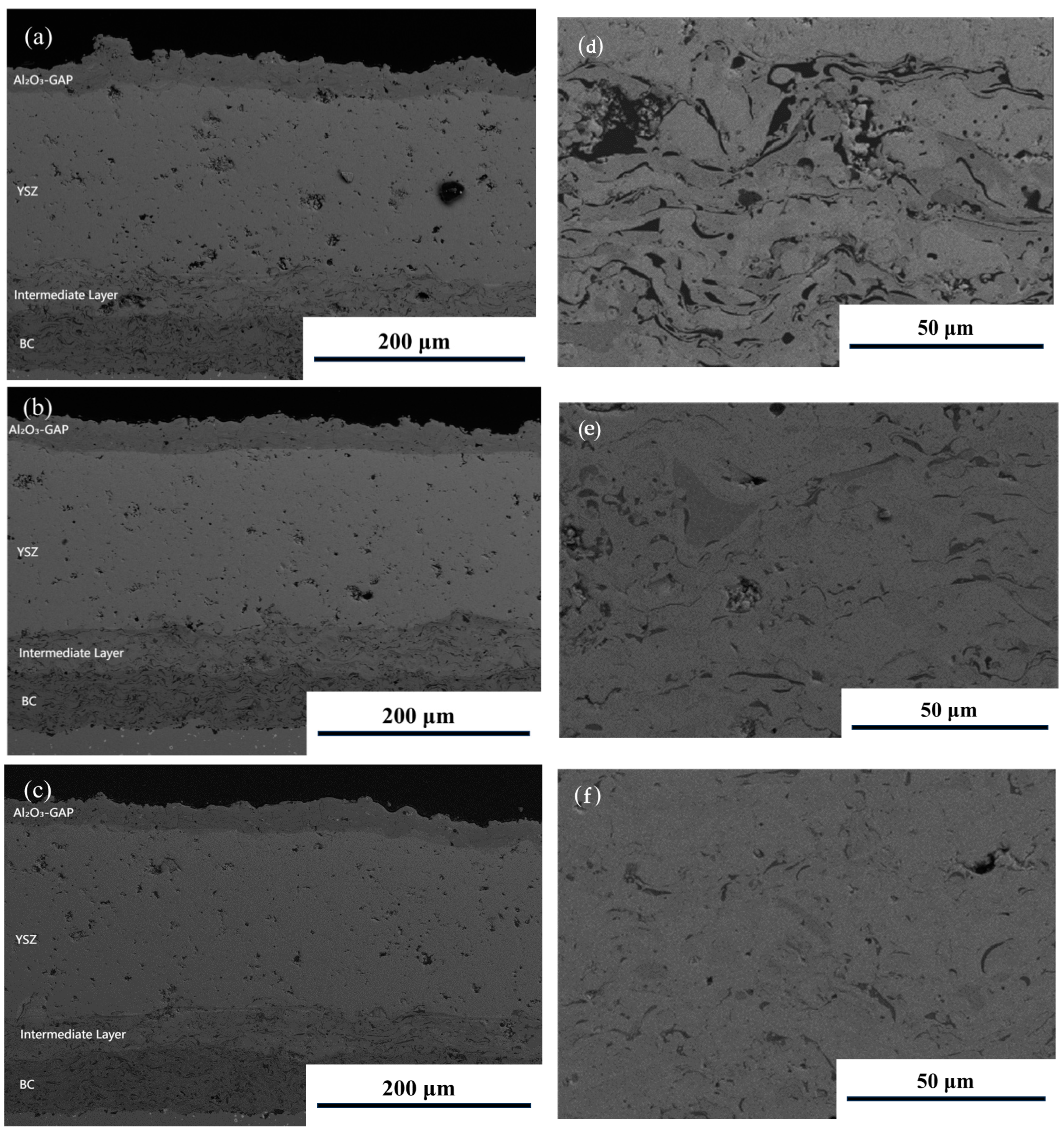
3.1.1. Microscopic Morphology of Sprayed Coatings

The sprayed state micromorphology of three sets of AYIB coating process samples is shown in Figure 2. In Figure 2, we can observe the layered interfaces of the multilayer coatings, indicating that good bonding is maintained between the layers. Due to the characteristics of atmospheric plasma spraying, we can see the presence of pores, unmelted particles, and interlayer microcracks inside the coating. These properties give the thermal barrier coating an excellent thermal insulation capability. The average porosity of the AGAP, YSZ, and intermediate layers is 6.21%, 11.94%, and 14.44% in Group A. The average porosity of the AGAP, YSZ, and intermediate layers is 6.21%, 11.94%, and 14.44% in Group B. The average porosity of the AGAP, YSZ, and intermediate layers is 6.21%, 11.94%, and 14.44% in Group B. The average porosities of the AGAP layer, YSZ layer, and intermediate layer in Group B samples were 6.68%, 11.95%, and 13.21%. The average porosities of the AGAP layer, YSZ layer, and intermediate layer in Group C samples were 6.44%, 11.26%, and 11.81%.
In the three groups of experiments, the spraying power, the speed of moving the gun, and the spraying distance of the intermediate transition layer were different in each group. In the regulation of the plasma spraying process parameters, it has been shown [27,28] that as the spraying power increases, the melting of the powder in the plasma jet is more adequate, and the flight speed increases, resulting in a smaller number and size of interlayer pores in the coating layer. It has been shown [9] that the deposition efficiency of the coating increases as the gun shift velocity decreases. This is because a lower gun transfer speed allows the sprayed material to remain on the substrate surface for a more extended period, which enhances the adhesion and densification of the coating and also helps improve the microstructure of the coating. In addition, the spraying distance also has a direct effect on the microstructure of the coating. R.A. Abbas et al. [40] showed that the pore size radius increased continuously, and the pore density increased when the spraying distance was increased from 70 mm to 130 mm. This suggests that more considerable spraying distances may lead to cooling and diffusion of the sprayed powder in flight, which results in the formation of more and larger pores and affects the densification and properties of the coating. Based on the aforementioned findings, among the three sample groups, the intermediate transition layer of the Group C coating exhibited the highest spraying power, the lowest gun shift speed, and the shortest spraying distance. Consequently, when compared to Group A and Group B, the intermediate transition layer of the Group C coating demonstrated superior performance in thermal shock tests. In addition, the AGAP layer has a dense microstructure, which is an excellent improvement for the erosion resistance of the coating. The microstructure and the phase transition process of the AGAP layer in the present experimental samples are consistent with our previous studies [30,31].

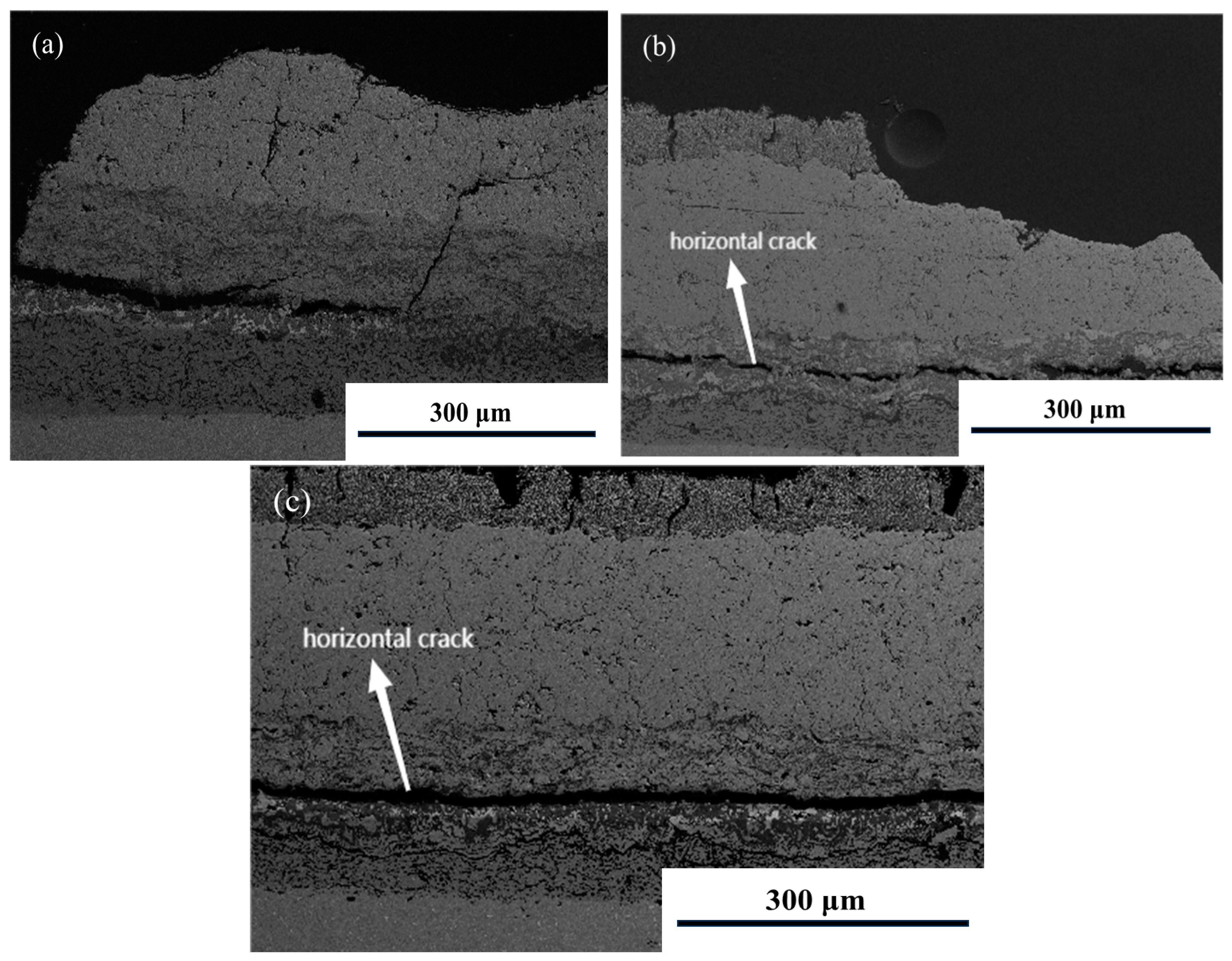
3.1.2. Thermal Shock Resistance

The service ambient temperature of AYB coating systems is usually 1100 °C, but in this experiment, the three thermal barrier coatings were exposed to an extreme thermal environment of 1500 °C. Therefore, instead of using the number of previous thermal shock cycles as a comparison criterion for coating life, the length of thermal shock at the highest temperature is used for comparison in this paper. Generally, in conventional thermal shock tests, the initial cracks originate from the edges of the samples and gradually spread to the neighboring regions due to the edge effect [41,42]. The experimental results showed that the samples underwent 1980 s at 1500 °C; the samples in Group A and Group B spalled, while the samples in Group C remained intact. The samples in Group C lasted for 2400 s in the thermal shock test before spalling. The failure micro-morphology of the three groups of thermal barrier coating samples after the thermal shock test is shown in Figure 3. By observing the micro-morphology of the three groups of coatings after thermal shock, we found that the failure location of the AYIB coating system changed in the high-temperature environment compared with the AYB coating system. All three AYIB coatings produced transverse cracks inside the intermediate transition layer, which expanded and eventually led to coating failure. In our previous studies [30,31], on the other hand, the failure mode of the AYB coatings was mainly characterized by cracks sprouting and expanding between the YSZ layer and the BC layer, leading to coating failure, with no apparent cracks inside the YSZ layer. The observed difference in thermal shock life, with Group C demonstrating superior performance relative to Groups A and B, can be primarily attributed to the higher spraying power applied to the intermediate transition layer in Group C. This resulted in a significant enhancement of the fracture toughness of the intermediate transition layer in Group C, in contrast to the lower fracture toughness observed in Groups A and B. Consequently, the intermediate transition layer in Group C exhibits a greater ability to resist crack initiation and propagation under thermal shock conditions, thereby improving its overall thermal shock resistance. The exposure time of the coatings in the thermal environment in this experiment was too short, and the effect of TGO on the thermal shock behavior of the coatings was ignored.

3.2. Simulation of Thermal Stress and Temperature Distributions of AYIB Coatings

The results of the thermal shock experiments show that adding an intermediate transition layer to the AYB coating system significantly changes the location of the coating crack initiation. In order to further investigate the differences in the thermal insulation performance and thermal stress distribution inside the coatings of AYB and AYIB coatings, numerical simulations of the temperature and stress fields of the two coatings were carried out in this paper using finite element software. In addition, the effects of different thicknesses of the intermediate transition layer on the thermal insulation performance of the substrate and the distribution of thermal stresses inside the coating are simulated.

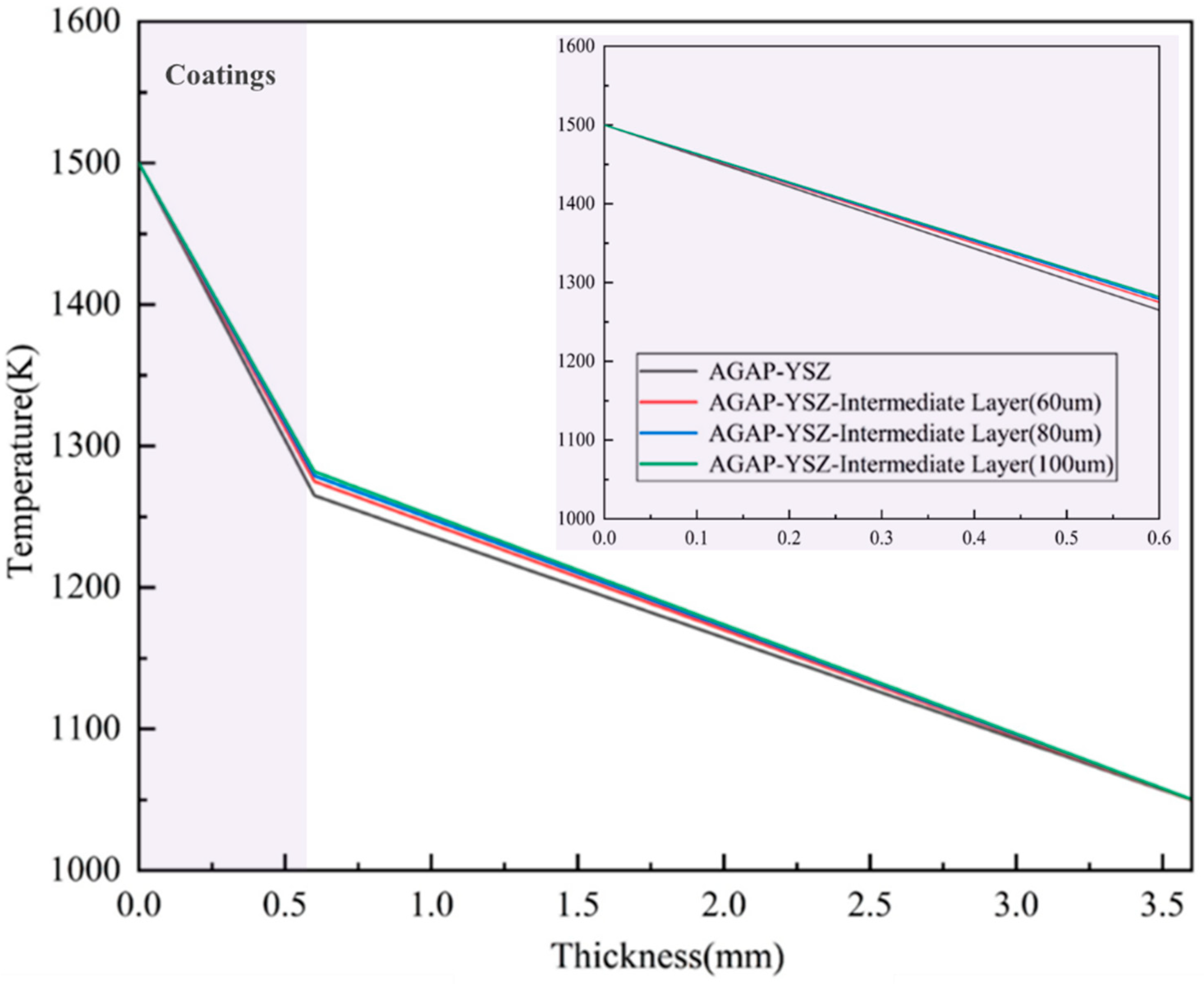
3.2.1. Temperature Distributions of AYIB Coatings

In this study, the temperature field of the AYIB coating system was first simulated using ABAQUS software (version 2022). During the simulation process, the thickness of the intermediate transition layer was varied, and the intermediate transition layers of 60 μm, 80 μm, and 100 μm were selected, respectively. The overall thickness of the TC layer was kept at 480 μm, so the corresponding thicknesses of the YSZ layer were set as 320 μm, 300 μm, and 280 μm, respectively. In addition, the thickness of the AGAP layer was set to 100 μm, and the thickness of the BC layer was set to 120 μm. Given that the focus of this part of the study is on the effects of different coating structures on the temperature and stress distribution during thermal shock at 1500 °C, the interfacial structures (e.g., roughness and oxides), as well as the complex feature structures (e.g., pores and cracks) within the APS coatings, were neglected during the simulation. In order to clarify the relationship between the specific value of the temperature distribution and the depth, the temperature data from the top of the coating to the top layer of the substrate and the bottom of the substrate along the right boundary path are plotted according to the position and direction of the arrows as shown in Figure 1. The plotting results are shown in Figure 4. For the AYB coating system, the temperature of the substrate surface did not reach 1275 °C in the high-temperature environment of 1500 °C. After the introduction of the intermediate transition layers of 60 μm, 80 μm, and 100 μm, the temperatures of the substrate surface were 1283 °C, 1287 °C, and 1294 °C, respectively. The simulation results show that the thermal insulation performance of the AYIB coating system decreases compared to that of the AYB coating system after introducing the intermediate transition layer. This is because the overall thickness of the coating, the AGAP layer, and the BC layer always remain constant, and the thickness of the YSZ layer decreases accordingly with the thickness of the intermediate transition layer. According to the compelling medium principle, the thermal conductivity of the intermediate transition layer is higher than that of the YSZ layer, so the overall thermal insulation performance of the coating decreases as the thickness of the transition layer increases.

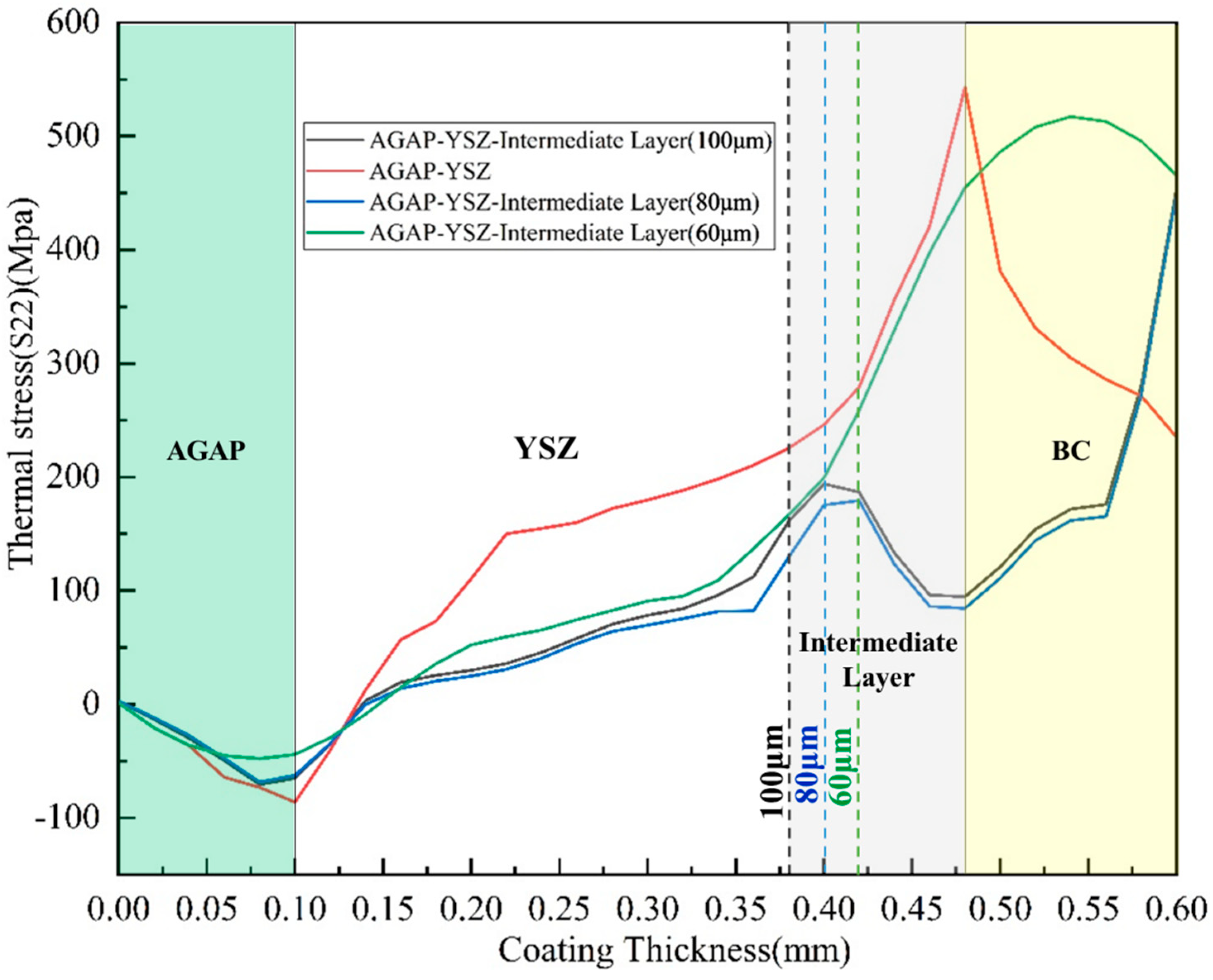
3.2.2. Thermal Stress Distribution of AYIB Coatings

In the flame thermal shock experiments, the main reason for the cracking of the coating interface is the thermal expansion mismatch between different materials due to the difference in thermal expansion coefficients, which generates thermal stresses. In the finite element simulation, this thermal stress manifests as tensile stress in the S22 direction. Figure 5 illustrates the variation in stress data along the right boundary path (Figure 1) for the AYIB coating system with different thicknesses of intermediate transition layers. As shown in Figure 5, the maximum thermal stress of the AYB coating system occurs between the YSZ layer and the BC layer under thermal shock conditions at 1500 °C, with a simulated stress value of 542.8 MPa. The location of the maximum thermal stress is the location of crack initiation and development, and the simulated results of AYB are consistent with the failure results after the actual thermal shock test. After the introduction of the intermediate transition layers of 80 μm and 100 μm, the maximum location of the maximum thermal stress of the AYIB coating system is shifted to the interface between the BC layer and the substrate compared with that of the AYB coating system. The simulated stress values are 457.1 MPa and 478.1 MPa, respectively, representing reductions of 15.79% and 11.92%. For the interior of the coating, the maximum thermal stress is within the intermediate transition layer, which is in line with the actual thermal shock assessment test results. However, when the intermediate transition layer with a thickness of 60 μm is introduced, the location of the maximum thermal stress of the AYIB coating system is within the BC layer, and the reduction in the maximum thermal stress is not noticeable compared with that of the AYB coating system. From the analysis results, increasing the thickness of the intermediate transition layer can effectively reduce the thermal stress within the coating and improve the strain tolerance of the coating.
The main reason for the different stress distributions of the two groups of coatings with different structures is due to the change in Young’s modulus of the TBC layer after introducing the intermediate transition layer, which is also a significant influence on thermal stress. According to a related study [43], the stresses in the coating and the substrate as a whole can usually be divided into three components:
σ c = σ a + σ g + σ t
σ a is aging stress, σ g is growth stress, and σ t is thermal expansion mismatch (CTE) stress coefficient. Aging stresses are internal stresses caused by changes in the organizational structure of a matrix material after it has undergone an aging treatment. During the aging process, the internal crystal structure of the material changes, which may lead to local changes in stress distribution, which are aging stresses. High-temperature deposition and rapid cooling usually involve preparing coatings or thin films. The different coefficients of thermal expansion between the deposited material and the substrate during the temperature change may lead to compressive or tensile stresses within the deposited layer. These stresses are growth stresses, and they may affect the coating’s adhesion, stability, and durability. CTE mismatch stresses are due to the mismatch between the coating material and the substrate in the coefficient of thermal expansion. When the coating material’s and substrate’s thermal expansion coefficients are different or mismatched, the two will generate internal stresses due to the different thermal expansion rates during temperature changes [43]. These stresses can be positive or negative, depending on the specific properties of the material and the temperature history during the coating preparation process, where the CTE mismatch stresses are calculated as follows [44]:
σ t = α c α s u b T E C 1 υ C
α c and α s u b are the coefficients of thermal expansion of the coating and the substrate, respectively; υ C is Poisson’s coating ratio, and T is the difference between the thermal shock test and initial temperatures. Therefore, according to Equation (2), when determining the thermal shock test temperature, a coating material with a coefficient of thermal expansion that better matches the substrate’s, a lower Young’s modulus, and a smaller Poisson’s ratio can be selected to alleviate thermal stresses caused by thermal expansion mismatch.

3.3. Simulation of Thermal Stress and Temperature Distributions of AYI(E)B Coatings

Through the above experimental and simulation results, we found that the intermediate transition layer in the AYB coating system can effectively alleviate the thermal stress generated by the coating under thermal shock. However, due to the high thermal conductivity of the intermediate transition layer, the thermal insulation performance of the AYIB coating is reduced. Although the thermal stress caused by the thermal expansion mismatch was mitigated by structural modulation, the thermal insulation effect of the coating on the substrate was affected. Therefore, the structure of the intermediate transition layer needs to be further optimized to achieve a balance between high strain tolerance and thermal insulation performance of the AYIB coating system.
In previous studies [45,46], we proposed a novel deposition method for porous thermal barrier coatings by improving the conventional APS technique, which successfully prepared porous EMAP coatings using co-sprayed micrometer-sized agglomerated particles as the pore source. The PEPC structure is a typical feature of EMAP coatings and is the main factor influencing the porosity of the coatings. Previous studies have shown that EMAP coatings have significant advantages in strain tolerance, thermal insulation capability, and sintering resistance. Therefore, in this paper, we have chosen to introduce the EMAP structure into the intermediate transition layer to improve the coating’s thermal insulation and strain tolerance. For ease of description, this novel coating system is referred to as AYI(E)B coating in this paper.
During the simulations in this section, we choose to blend three different contents (volume share) of PEPC, 3%, 6%, and 9%, inside the intermediate transition layer to analyze the effect of different contents of PEPC on the thermal insulation performance and strain tolerance of the AYI(E)B coating system. The geometric modeling of the finite element model is shown in Figure 6. Previous studies [17,18] have shown through microscopic observations that PEPC particles have an approximately ellipsoidal shape, resembling flattened spheres. In a 2D plane, they can be simplified as standard ellipses with a perimeter of 50 μm and a length-to-width ratio of 1:2. In addition, the material parameters of PEPC were kept consistent with previous studies [32,33], where the thermal conductivity of PEPC was set to 0.025 W/m-K and the modulus of elasticity to 140 kPa. The thickness of the intermediate transition layer was set to 80 μm. The rest of the coating thicknesses and material parameters were consistent.

3.3.1. Temperature Distributions of AYI(E)B Coatings

Figure 7 illustrates the temperature change profiles of AYI(E)B coatings with different PEPC contents along the right boundary path (Figure 1) under thermal shock at 1500 °C. When the PEPC content in the intermediate transition layer is 3%, 6%, and 9%, the temperatures reaching the substrate surface are 1203 °C, 1193 °C, and 1183 °C, respectively. The simulation results show that the temperature of the substrate surface decreases gradually with the increase in the PEPC content in the intermediate transition layer. This indicates that the thermal insulation ability of the coating is positively correlated with the content of PEPC, and the higher the content of PEPC, the better the thermal insulation performance of the coating. Compared with the AYIB coating system, the thermal insulation performance of the AYI(E)B coating system was greatly improved.

3.3.2. Thermal Stress Distribution of AYI(E)B Coatings

Figure 8 illustrates the stress distribution cloud of AYI(E)B coatings with different PEPC contents under thermal shock at 1500 °C and the stress variation curves along the right boundary path (Figure 1). The simulation results show that the location of the maximum thermal stress in the AYI(E)B system is at the interface between the BC layer and the substrate after the introduction of the EMAP structure in the intermediate transition layer. For the inside of the coating, the maximum thermal stress values within the coating for the AYI(E)B coating system were 194.7 MPa, 175.5 MPa, and 171.9 MPa when 3%, 6%, and 9% of PEPC were introduced, respectively, and the locations were all inside the intermediate transition layer. In addition, the maximum intra-coating thermal stresses of the AYI(E)B coating system appeared inside the intermediate transition layer, with values of 150.39 MPa, 146.85 MPa, and 99.01 MPa, respectively. Compared with the AYIB coating system, the overall S22 stresses of the AYI(E)B coating system were reduced, and the strain tolerances were improved, further mitigating the thermal stress of the coating system. Compared to the traditional APS structure, the EMAP structure coating demonstrates superior resistance to sintering shrinkage and exhibits a lower degree of sintering hardening. This allows it to maintain a lower elastic modulus, even after prolonged exposure to high temperatures [32]. While the substrate stiffness of conventional structural coatings increases dramatically during sintering at high temperatures, the effective modulus of elasticity of EMAP coatings with embedded particles is reduced by approximately 75% compared to conventional coatings without particles, which mitigates thermal stresses due to thermal expansion mismatches in high-temperature environments. This property significantly improves the strain tolerance of the coating at high temperatures and increases the thermal shock life of the coating.
In summary, the AYI(E)B coating system has less thermal stress and better thermal insulation capability than the AYIB coating system. On the one hand, the EMAP intermediate transition layer adopts a porous structure. It contains many second-phase particles, which not only enhances the anti-sintering property of the coating but also improves its thermal insulation effect, thus effectively reducing the thermal stress of the coating at high temperatures. On the other hand, incorporating second-phase particles reduced Young’s modulus of the intermediate transition layer of EMAP; according to the analysis of Equation (2), the reduction in Young’s modulus helps reduce the stresses induced by CTE mismatch in the coating system, further enhancing the coating lifetime. Therefore, as shown in Figure 9, we propose a novel design scheme for the AYI(E)B multilayer thermal barrier coating.

4. Conclusions

This study presents a novel thermal barrier coating system incorporating an intermediate transition layer. Three different AGAP/YSZ/intermediate layer/bond coat systems were fabricated and subjected to a 1500 °C flame thermal shock test. At the same time, finite element simulations of flame thermal shock at 1500 °C were carried out for the AGAP/YSZ/bonded coating system and AGAP/YSZ/intermediate layer/bonded coating system. Although the introduction of an intermediate transition layer increases the complexity of the spraying process, as well as the preparation time and cost of the coating, both experimental and simulation analyses indicate that this layer effectively alleviates thermal stresses during thermal shock, thereby significantly enhancing the strain tolerance of the coating. On this basis, this study further modulates the structure of the AGAP/YSZ/intermediate/bonding layer coating system and designs a new coating system for the AGAP/YSZ/EMAP intermediate/bonding layer. The finite element simulation results show that introducing the EMAP structure relieves the thermal stress during thermal shock and increases the strain tolerance of the coating but also improves its thermal insulation performance. The main conclusions of this study are summarized as follows:
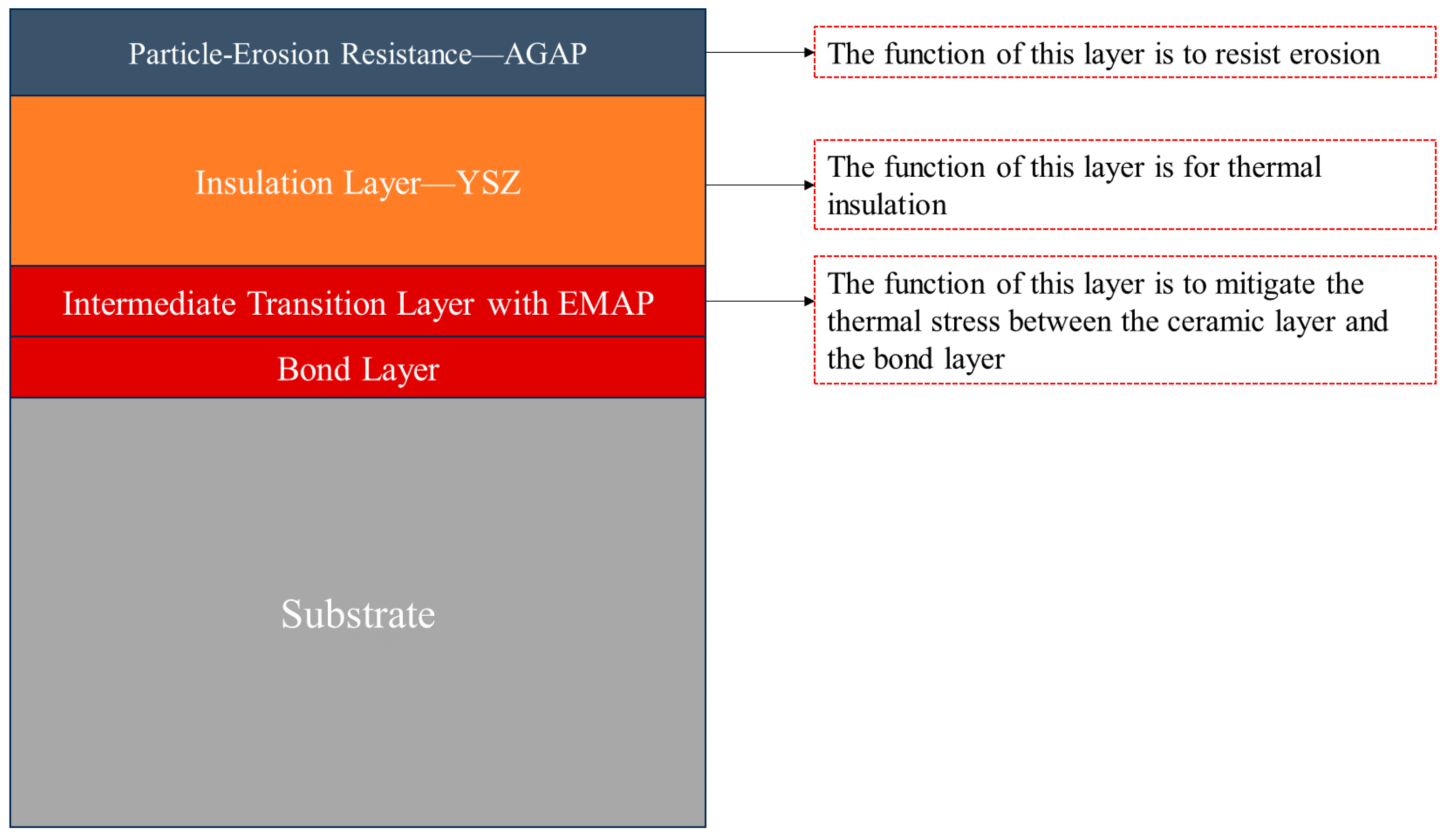
  • By analyzing the results of the flame thermal shock experiments on the AYIB coating system at 1500 °C, the coating’s failure mode changes due to the introduction of the intermediate transition layer, and the location of crack generation moves from the interface between the BC layer and the ceramic layer to the interior of the intermediate transition layer.
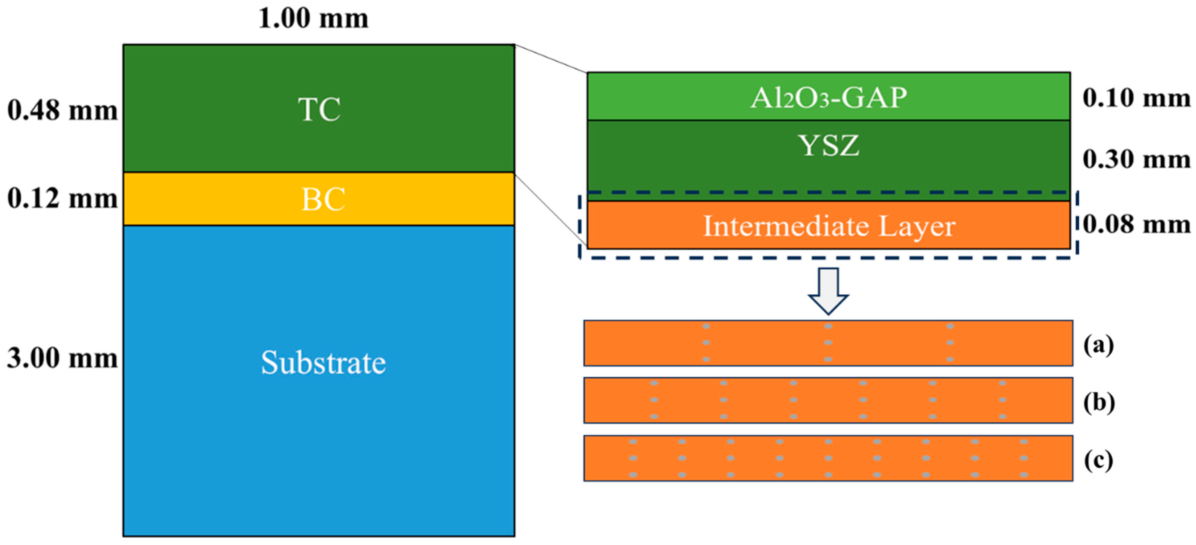
  • The thermal insulation performance of the coating decreases slightly due to the introduction of the intermediate transition layer. For the AYB system, the temperature of the substrate surface is 1275 °C in a high-temperature environment of 1500 °C. After the introduction of the intermediate transition layers of 60 μm, 80 μm, and 100 μm, the temperatures of the substrate surface are 1283 °C, 1287 °C, and 1294 °C, respectively.
  • Compared with the AYB coating system without an intermediate transition layer, the thermal mismatch stresses caused by thermal expansion mismatch in the high-temperature thermal shock experiments are significantly alleviated by adding different thicknesses of the intermediate transition layer in the AYIB coating system. When the thickness of the intermediate transition layer is 80 μm and 100 μm, the maximum thermal stresses are 457.1 MPa and 478.1 MPa, respectively, 15.78% and 12.12% are reduced.
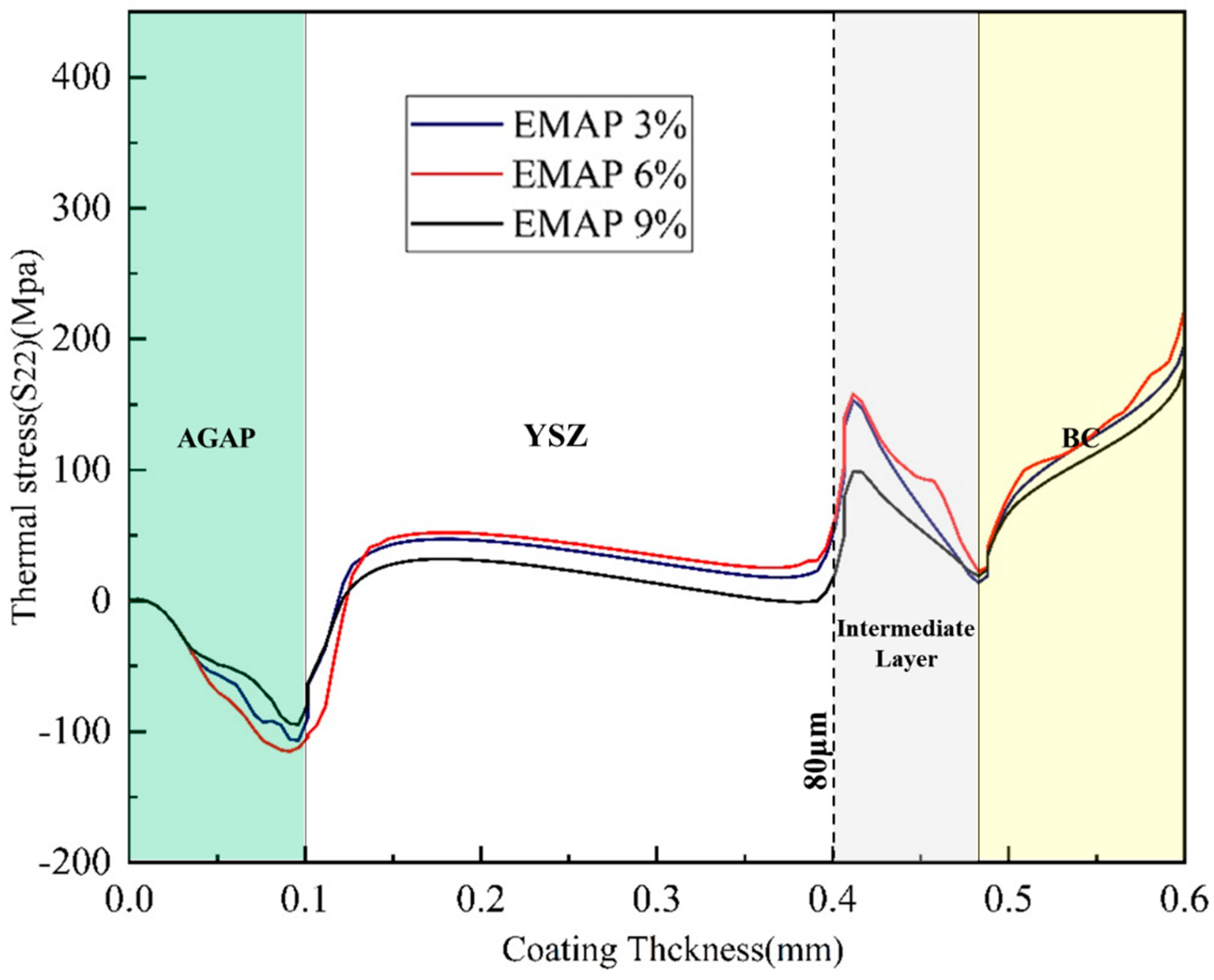
  • The coatings’ strain tolerance and thermal insulation properties were significantly improved by introducing the EMAP structure in the intermediate transition layer. When the contents of second-phase embedded particles were 3%, 6%, and 9%, respectively, the maximum thermal stresses inside the coatings were 150.39 MPa, 146.85 MPa, and 99.01 MPa. The temperatures on the substrate surface were 1203 °C, 1193 °C, and 1183 °C, respectively. The increase in the second-phase particle content effectively relieves the thermal stress inside the coating and enhances the thermal insulation performance of the coating system.

Author Contributions

Conceptualization, P.L., S.Y. and W.W.; methodology, P.L. and S.Y.; software, S.Y.; validation, P.L., S.Y., W.W., K.L., Y.L. and T.Y.; formal analysis, P.L. and S.Y.; investigation, P.L., S.Y. and K.L.; resources, W.W.; data curation, P.L. and S.Y.; writing—original draft preparation, P.L.; writing—review and editing, W.W.; visualization, P.L.; supervision, W.W.; project administration, W.W.; funding acquisition, W.W. All authors have read and agreed to the published version of the manuscript.

Funding

This research was funded by the Science Center for Gas Turbine Project (P2021-A-IV-002-002), Civil Space ‘the 14th Five-Year Plan’ Pre-research Project (D050101), National High Technology Research and Development Program of China (2023YFB3711200), National Natural Science Foundation of China (52175136, 52130511), Shanghai Gaofeng Project for University Academic Program Development.

Institutional Review Board Statement

Not applicable.

Informed Consent Statement

Not applicable.

Data Availability Statement

The raw/processed data required to reproduce these findings cannot be shared at this time as the data also forms part of an ongoing study.

Acknowledgments

The author thanks the contribution of W.W. for reviewing and discussing this work; S.Y. for providing experimental support for SEM microstructural analysis; Y.L. and T.Y. for discussing experimental results; and the Research Center of Analysis and Test of East China University of Science and Technology for the help on the characterization.

Conflicts of Interest

The authors declare no conflicts of interest.

References

  1. Guo, H.; Guo, Y.; Xue, Z.; Gong, S.; Xu, H. Overview of thermal barrier coatings for advanced gas turbine engine. In Thermal Barrier Coatings; Woodhead Publishing: Cambridge, UK, 2023; pp. 1–20. [Google Scholar]
  2. Cao, X.Q.; Vassen, R.; Stoever, D. Ceramic materials for thermal barrier coatings. J. Eur. Ceram. Soc. 2004, 24, 1–10. [Google Scholar] [CrossRef]
  3. Clarke, D.R.; Oechsner, M.; Padture, N.P. Thermal-barrier coatings for more efficient gas-turbine engines. MRS Bull. 2012, 37, 891–898. [Google Scholar] [CrossRef]
  4. Padture, N.P.; Gell, M.; Jordan, E.H. Thermal Barrier Coatings for Gas-Turbine Engine Applications. Science 2002, 296, 280–284. [Google Scholar] [CrossRef] [PubMed]
  5. Feuerstein, A.; Knapp, J.; Taylor, T.; Ashary, A.; Bolcavage, A.; Hitchman, N. Technical and Economical Aspects of Current Thermal Barrier Coating Systems for Gas Turbine Engines by Thermal Spray and EBPVD: A Review. J. Therm. Spray Technol. 2008, 17, 199–213. [Google Scholar] [CrossRef]
  6. Wright, P.K.; Evans, A.G. Mechanisms governing the performance of thermal barrier coatings. Curr. Opin. Solid State Mater. Sci. 1999, 4, 255–265. [Google Scholar] [CrossRef]
  7. Dong, H.; Liang, X.; Wang, Z.; Luo, N.; Zhang, J.; Zhan, Y.; Zhang, X. Enhancing the performances of EB-PVD TBCs via overlayer Al-modification. Surf. Coat. Technol. 2023, 473, 130001. [Google Scholar] [CrossRef]
  8. Fang, H.J.; Wang, W.Z.; Yang, Z.N.; Yang, T.; Wang, Y.H.; Huang, J.B.; Ye, D.D. Phase stability, thermal shock behavior and CMAS corrosion resistance of Yb2O3-Y2O3 co-stabilized zirconia thermal barrier coatings prepared by atmospheric plasma spraying. Surf. Coat. Technol. 2021, 427, 127864. [Google Scholar] [CrossRef]
  9. Kulkarni, A.; Vaidya, A.; Goland, A.; Sampath, S.; Herman, H. Processing effects on porosity-property correlations in plasma sprayed yttria-stabilized zirconia coatings. Mater. Sci. Eng. A 2003, 359, 100–111. [Google Scholar] [CrossRef]
  10. Li, G.R.; Yang, G.J.; Li, C.X.; Li, C.J. Sintering characteristics of plasma-sprayed TBCs: Experimental analysis and an overall modelling. Ceram. Int. 2018, 44, 2982–2990. [Google Scholar] [CrossRef]
  11. Trice, R.W.; Su, Y.J.; Mawdsley, J.R.; Faber, K.T.; De Arellano-López, A.R.; Wang, H.; Porter, W.D. Effect of heat treatment on phase stability, microstructure, and thermal conductivity of plasma-sprayed YSZ. J. Mater. Sci. 2002, 37, 2359–2365. [Google Scholar] [CrossRef]
  12. Lashmi, P.; Ananthapadmanabhan, P.; Unnikrishnan, G.; Aruna, S. Present status and future prospects of plasma sprayed multilayered thermal barrier coating systems. J. Eur. Ceram. Soc. 2020, 40, 2731–2745. [Google Scholar] [CrossRef]
  13. Vaßen, R.; Jarligo, M.O.; Steinke, T.; Mack, D.E.; Stöver, D. Overview on advanced thermal barrier coatings. Surf. Coat. Technol. 2010, 205, 938–942. [Google Scholar] [CrossRef]
  14. Fang, H.J.; Wang, W.Z.; Huang, J.B.; Li, Y.J.; Ye, D.D. Corrosion behavior and thermos-physical properties of a promising Yb2O3 and Y2O3 co-stabilized ZrO2 ceramic for thermal barrier coatings subject to calcium-magnesium-aluminum-silicate (CMAS) deposition: Experiments and first-principles calculation. Corros. Sci. 2021, 182, 109230. [Google Scholar] [CrossRef]
  15. McPherson, R. A review of microstructure and properties of plasma sprayed ceramic coatings. Surf. Coat. Technol. 1989, 40, 173–181. [Google Scholar] [CrossRef]
  16. Li, C.; Wang, W. Quantitative characterization of lamellar microstructure of plasma-sprayed ceramic coatings through visualization of void distribution. Mater. Eng. A 2004, 386, 10–19. [Google Scholar] [CrossRef]
  17. Allen, A.; Ilavsky, J.; Long, G.; Wallace, J.; Berndt, C.; Herman, H. Microstructural characterization of yttria-stabilized zirconia plasma-sprayed deposits using multiple small-angle neutron scattering. Acta Mater. 2001, 49, 1661–1675. [Google Scholar] [CrossRef]
  18. Antou, G.; Montavon, G.; Hlawka, F.; Cornet, A.; Coddet, C.; Machi, F. Evaluation of modifications induced on pore network and structure of partially stabilized zirconia manufactured by hybrid plasma spray process. Surf. Coat. Technol. 2004, 180, 627–632. [Google Scholar] [CrossRef]
  19. Fauchais, P.; Vardelle, M.; Goutier, S. Latest Researches Advances of Plasma Spraying: From Splat to Coating Formation. J. Therm. Spray Technol. 2016, 25, 1534–1553. [Google Scholar] [CrossRef]
  20. Kulkarni, A.A.; Goland, A.; Herman, H.; Allen, A.J.; Ilavsky, J.; Long, G.G.; Johnson, C.A.; Ruud, J.A. Microstructure–Property Correlations in Industrial Thermal Barrier Coatings. J. Am. Ceram. Soc. 2004, 87, 1294–1300. [Google Scholar] [CrossRef]
  21. Fleck, N.; Cocks, A.; Lampenscherf, S. Thermal shock resistance of air plasma sprayed thermal barrier coatings. J. Eur. Ceram. Soc. 2014, 34, 2687–2694. [Google Scholar] [CrossRef]
  22. Heveran, C.M.; Xu, J.; Sarin, V.K.; Basu, S.N. Simulation of stresses in TBC–EBC coating systems for ceramic components in gas turbines. Surf. Coat. Technol. 2013, 235, 354–360. [Google Scholar] [CrossRef]
  23. Levi, C.G. Emerging materials and processes for thermal barrier systems. Curr. Opin. Solid State Mater. Sci. 2004, 8, 77–91. [Google Scholar] [CrossRef]
  24. Ozgurluk, Y.; Gulec, A.; Ozkan, D.; Binal, G.; Karaoglanli, A.C. Structural characteristics, oxidation performance and failure mechanism of thermal barrier coatings fabricated by atmospheric plasma spraying and detonation gun spraying. Eng. Fail. Anal. 2023, 152, 107499. [Google Scholar] [CrossRef]
  25. Scrivani, A.; Rizzi, G.; Berndt, C.C. Enhanced thick thermal barrier coatings that exhibit varying porosity. Mater. Sci. Eng. A 2008, 476, 1–7. [Google Scholar] [CrossRef]
  26. Tao, S.; Yang, J.; Shao, F.; Zhao, H.; Zhong, X.; Zhuang, Y.; Sheng, J.; Ni, J.; Li, Q.; Tao, S. Atmospheric plasma sprayed thick thermal barrier coatings: Microstructure, thermal shock behaviors and failure mechanism. Eng. Fail. Anal. 2021, 131, 105819. [Google Scholar] [CrossRef]
  27. Liu, K.; Tang, J.; Bai, Y.; Yang, Q.; Wang, Y.; Kang, Y.; Zhao, L.; Zhang, P.; Han, Z. Particle in-flight behavior and its influence on the microstructure and mechanical property of plasma sprayed La2Ce2O7 thermal barrier coatings. Mater. Sci. Eng. A 2015, 625, 177–185. [Google Scholar] [CrossRef]
  28. Liu, L.; Wang, S.; Zhang, B.; Jiang, G.; Liu, H.; Yang, J.; Wang, J.; Liu, W. Present status and prospects of nanostructured thermal barrier coatings and their performance improvement strategies: A review. J. Manuf. Process. 2023, 97, 12–34. [Google Scholar] [CrossRef]
  29. Pakseresht, A.; Sharifianjazi, F.; Esmaeilkhanian, A.; Bazli, L.; Nafchi, M.R.; Bazli, M.; Kirubaharan, K. Failure mechanisms and structure tailoring of YSZ and new candidates for thermal barrier coatings: A systematic review. Mater. Des. 2022, 222, 111044. [Google Scholar] [CrossRef]
  30. Yang, Z.; Wang, W.; Deng, S.; Fang, H.; Yang, T.; Wang, L. Thermal Shock Behavior and Particle Erosion Resistance of Toughened GZ Coatings Prepared by Atmospheric Plasma Spraying. Coatings 2021, 11, 1477. [Google Scholar] [CrossRef]
  31. Yang, Z.; Yang, K.; Wang, W.; Yang, T.; Fang, H.; Qiang, L.; Zhang, X.; Zhang, C. Investigation of Thermal Shock Behavior of Multilayer Thermal Barrier Coatings with Superior Erosion Resistance Prepared by Atmospheric Plasma Spraying. Coatings 2022, 12, 804. [Google Scholar] [CrossRef]
  32. Yang, T.; Wang, W.; Huang, J.; Wang, L.; Yang, Z.; Fang, H.; Ye, D. Thermal Shock Resistance and Bonding Strength of Novel-Structured Thermal Barrier Coatings with Different Microstructure. J. Therm. Spray Technol. 2022, 31, 1540–1555. [Google Scholar] [CrossRef]
  33. Yang, T.; Wang, W.; Tang, Z.; Liu, Y.; Li, K. Structural optimization for porous thermal barrier coating and analysis of thermomechanical properties by experimental and computational investigation. Surf. Coat. Technol. 2023, 458, 129347. [Google Scholar] [CrossRef]
  34. Yedida, V.S.; Vasudev, H. A review on the development of thermal barrier coatings by using thermal spray techniques. Mater. Today Proc. 2022, 50, 1458–1464. [Google Scholar] [CrossRef]
  35. Song, J.-B.; Wang, L.-S.; Dong, H.; Yao, J.-T. Long lifespan thermal barrier coatings overview: Materials, manufacturing, failure mechanisms, and multiscale structural design. Ceram. Int. 2022, 49, 1–23. [Google Scholar] [CrossRef]
  36. Huang, J.; Wang, W.; Lu, X.; Liu, S.; Li, C. Influence of Lamellar Interface Morphology on Cracking Resistance of Plasma-Sprayed YSZ Coatings. Coatings 2018, 8, 187. [Google Scholar] [CrossRef]
  37. Kim, D.-J.; Shin, I.-H.; Koo, J.-M.; Seok, C.-S.; Lee, T.-W. Failure mechanisms of coin-type plasma-sprayed thermal barrier coatings with thermal fatigue. Surf. Coat. Technol. 2010, 205, S451–S458. [Google Scholar] [CrossRef]
  38. Yang, T.; Wang, W.; Tang, Z.; Liu, Y.; Li, K.; Liu, W.; Zhang, W.; Ye, D. CMAS infiltration behavior of atmospheric plasma-sprayed thermal barrier coating with tailored pore structures. Ceram. Int. 2023, 50, 7218–7229. [Google Scholar] [CrossRef]
  39. Cai, Z.; Zhang, Z.; Liu, Y.; Zhao, X.; Wang, W. Numerical Study on Effect of Non-uniform CMAS Penetration on TGO Growth and Interface Stress Behavior of APS TBCs. Chin. J. Mech. Eng. 2021, 34, 128. [Google Scholar] [CrossRef]
  40. Abbas, R.A.; Ajeel, S.A.; Bash, M.A.A.; Kadhim, M.J. Effect of plasma spray distance on the features and hardness reliability of YSZ thermal barrier coating. Mater. Today Proc. 2021, 42, 2553–2560. [Google Scholar] [CrossRef]
  41. Jamali, H.; Mozafarinia, R.; Razavi, R.S.; Ahmadi-Pidani, R. Comparison of thermal shock resistances of plasma-sprayed nanostructured and conventional yttria stabilized zirconia thermal barrier coatings. Ceram. Int. 2012, 38, 6705–6712. [Google Scholar] [CrossRef]
  42. Wu, J.; Guo, H.-B.; Zhou, L.; Wang, L.; Gong, S.-K. Microstructure and Thermal Properties of Plasma Sprayed Thermal Barrier Coatings from Nanostructured YSZ. J. Therm. Spray Technol. 2010, 19, 1186–1194. [Google Scholar] [CrossRef]
  43. Li, K.; Wang, W.; Yang, S.; Liu, Y.; Yang, T. First-principles calculations and thermal-mechanical experimental studies on middle-entropy rare-earth disilicates. Ceram. Int. 2024, 50, 22290–22305. [Google Scholar] [CrossRef]
  44. Li, K.; Wang, W.; Yang, T.; Liu, Y. Simulation of 1500 °C Thermal Shock for Novel Structural Thermal/Environmental Barrier Coatings System. Coatings 2023, 13, 96. [Google Scholar] [CrossRef]
  45. Huang, J.B.; Wang, W.Z.; Li, Y.J.; Fang, H.J.; Ye, D.D.; Zhang, X.C.; Tu, S.T. Improve durability of plasma-sprayed thermal barrier coatings by decreasing sintering-induced stiffening in ceramic coatings. J. Eur. Ceram. Soc. 2020, 40, 1433–1442. [Google Scholar] [CrossRef]
  46. Huang, J.B.; Wang, W.Z.; Li, Y.J.; Fang, H.J.; Ye, D.D.; Zhang, X.C.; Tu, S.T. A novel strategy to control the microstructure of plasma-sprayed YSZ thermal barrier coatings. Surf. Coat. Technol. 2020, 402, 126304. [Google Scholar] [CrossRef]
Figure 1. Schematic of the Geometrical Model for Finite Element Simulation (the red arrow represents the path to the data extraction location).
Coatings 14 01614 g001
Figure 2. Cross-sectional morphologies of the as-sprayed (a,d) Group A, (b,e) Group B, and (c,f) Group C.
Coatings 14 01614 g002
Figure 3. Cross-sectional morphologies of coatings after thermal shock test (a) Group A, (b) Group B, (c) Group C.
Coatings 14 01614 g003
Figure 4. Temperature data plots of AYIB coatings with different intermediate transition layer thicknesses along the right boundary path at 1500 °C.
Coatings 14 01614 g004
Figure 5. Distribution of coating internal stresses along the right boundary path at 1500 °C for AYIB coatings with different intermediate transition layer thicknesses.
Coatings 14 01614 g005
Figure 6. Finite element model of AYI(E)B with different PEPC contents: (a) 3%; (b) 6%; (c) 9%.
Coatings 14 01614 g006
Figure 7. Temperature data plots of AYI(E)B coatings with different intermediate transition layer thicknesses along the right boundary path at 1500 °C.
Coatings 14 01614 g007
Figure 8. Stress distribution along the right boundary path at 1500 °C for coatings with different PEPC contents.
Coatings 14 01614 g008
Figure 9. AYI(E)B multilayer thermal barrier coating design solution.
Coatings 14 01614 g009
Table 1. Plasma spraying parameters.
ParameterBCYSZIntermediate Layer of AIntermediate Layer of BIntermediate Layer of CAGAP
Current, A550600550575600650
Voltage, V68.567.268.567.967.267
Primary gas flow rate, Ar, L/min505050455040
Carrier gas flow rate,   H 2 , L/min8988.599
Spray distance, mm1209012010590120
Travers speed of gun, mm/s900500900700500900
Powder feeding rate, %102010152020
Thickness, μm120300808080100
Table 2. Thermodynamic parameters of the intermediate transition layer.
Temperature
(°C)
Elastic Modulus
(109 Pa)
Coefficient of Thermal Expansion
(10−6 °C−1)
Density
(103 kg/m3)
Thermal Conductivity
(W/m·°C)
Thermal Capacity
(J/kg·°C)
Poisson Rate
2012012.76.693.54250.2
200 13.2 4.345 0.2
400 13.5 5.34 0.21
600 14.1 6.575 0.21
800 15.2 7.83 0.22
1000 16.2 8.67 0.23
1100 16.7 9.06 0.23
Disclaimer/Publisher’s Note: The statements, opinions and data contained in all publications are solely those of the individual author(s) and contributor(s) and not of MDPI and/or the editor(s). MDPI and/or the editor(s) disclaim responsibility for any injury to people or property resulting from any ideas, methods, instructions or products referred to in the content.

