Article

Modification of Microstructure and Properties of Cold-Sprayed AlSi10Mg+TiB2 Composite by Friction Stir Process

Key Laboratory for Light-Weight Materials, Nanjing Tech University, Nanjing 211816, China
*
Authors to whom correspondence should be addressed.
Coatings 2024, 14(12), 1509; https://doi.org/10.3390/coatings14121509
Submission received: 25 October 2024 / Revised: 23 November 2024 / Accepted: 28 November 2024 / Published: 29 November 2024

Abstract

:
This study investigates the influence of friction stir processing (FSP) on the microstructure, microhardness, and tribological properties of cold-sprayed AlSi10Mg+TiB2 composite coatings on Al substrates. Due to the limitation of particle deformation during cold spraying, there were still some porosities and poorly bonded regions in the as-deposited AlSi10Mg+TiB2 composite coating, which decreased the mechanical performance. Applying FSP to the composite coating significantly reduced the porosity and improved metallurgical bonding. Further, the FSP process induced severe plastic deformation, leading to a more uniform distribution of TiB2 particles and a homogenized microstructure in the composite coating. The microhardness decreases progressively from the unaffected region through the heat-affected zone and thermomechanical-affected zone, and ultimately reaches its lowest value in the stir zone. The decreased microhardness is primarily attributed to the removal of the work-hardening effect. The FSP treatment seems to have little impact on the wear performance for both the pure AlSi10Mg and AlSi10Mg+TiB2 composite samples, as the coefficient of friction values and wear rates remain essentially unchanged after the FSP treatments.

1. Introduction

Cold spraying (CS) is a solid-state deposition technique extensively used for surface modification, component repair, and net-shaped part manufacturing [1,2]. Unlike thermal spray and laser-based additive manufacturing (AM) processes, CS works at temperatures far below the material’s melting point [3]. By utilizing inert gas to accelerate the raw powder to supersonic speeds and spraying it onto the substrate, CS eliminates the need for particle melting or solidification. This process minimizes defects like oxidation, phase transformations, and grain growth [4,5,6]. This technology demonstrates significant potential in industries such as automotives and aerospace [7,8].
During the CS process, materials are deposited layer by layer through localized metallurgical bonding and mechanical interlocking, but the bonding at the particle interfaces tends to be weak [9,10,11]. Additionally, gases may be trapped between particles during deposition, leading to the formation of pores within the coating [12]. These defects not only reduce the mechanical performance of the coating but also weaken its bonding strength with the substrate. Moreover, the intense plastic deformation during deposition induces a localized work-hardening effect. This reduces the coating’s ductility, leading to brittleness and an uneven microstructure. For example, Maharjan et al. [13] reported that the porosity of samples deposited by CS was 10%, with a weak interfacial bonding strength of 37 MPa. Judas et al. [14] found that the elongation of 7075 Al samples deposited by CS did not exceed 3%. These issues limit the widespread application of CS in high-strength, load-bearing components. To address these limitations, researchers have investigated the prospects of CS in comparison with other techniques, revealing its unique advantages. For instance, Kromer et al. [15] showed that combining laser surface texturing with cold spraying can greatly improve the coating adhesion by enhancing the interface contact quality. Similarly, Shtansky et al. [16] highlighted the ability of CS to produce Ti coatings with controlled surface roughness and wettability, showcasing its versatility in biomedical and structural applications. These studies underline the growing potential of CS in diverse fields while emphasizing the need for effective post-treatment techniques to overcome its inherent limitations.
Friction stir processing (FSP) has been proven to be an effective post-treatment method for overcoming these challenges, offering notable advantages. FSP effectively reduces the porosity of CS coatings and enhances interparticle bonding through intense plastic deformation, leading to improved mechanical properties. For instance, Wang et al. [17] reported a 64% reduction in porosity for CS pure Al samples via post-FSP treatment, with the yield strength (YS), ultimate tensile strength (UTS), and elongation increasing by 38%, 45%, and 1336%, respectively. Liu et al. [18] prepared a 6061Al alloy using a combination of CS and FSP. After processing, the grain structure was significantly refined, with an average grain size of 3.1 μm. The microhardness, UTS, and elongation increased by 22%, 171%, and 683%, respectively. Similarly, Cui et al. [19] used a combined solution of FSP and CS to fabricate high-ductility nano-Al2O3 dispersion-strengthened Cu. This approach increased the tensile strength from 210 MPa to 450 MPa, and the elongation from 1% to 35%. This improvement is primarily attributed to significant grain refinement and the overall enhancement of interfacial bonding.
Recent research on the FSP treatment of Al matrix composites (AMCs) has shown promising progress, highlighting its strong potential for repairing CS-induced defects and improving the overall material performance. For instance, Hodder et al. [20] reported that post-FSP treatment improved the microhardness of cold-sprayed Al2O3/Al composite by re-distributing and refining Al2O3 particles. The incorporation of ceramic particles into the Al matrix can greatly enhance their wear resistance and microhardness [21,22]. However, the current method of introducing ceramic reinforcement phases typically involves mixed powder preparation. In samples produced by this approach, the wettability between the ceramic phase and the matrix is often poor, resulting in weak interfacial bonding, along with issues such as an uneven distribution of the ceramic reinforcement phase [20]. Therefore, it is necessary to develop a new CS+FSP avenue that allows for the development of AMCs with uniformly distributed reinforcements and robust interfacial bonding between the reinforcement and Al matrix.
In this study, a gas-atomized AlSi10Mg+TiB2 composite powder reinforced with in situ-formed TiB2 particles was used as the feedstock to fabricate AMC components by CS. The primary objective of this study is to evaluate the influence of FSP on reducing porosity, enhancing interfacial bonding, homogenizing particle distribution, and analyzing its effects on the microhardness and tribological properties of cold-sprayed AlSi10Mg+TiB2 composite coatings. In order to further modify the microstructure and improve the mechanical properties of the as-deposited deposits, post-FSP treatment was performed in different conditions. The effect of the processing parameters on the microstructure evolution, microhardness, and friction properties of the AlSi10Mg+TiB2 composite was investigated in terms of scanning (SEM) and transmission electron microscopy (TEM), microhardness, and tribological tests.

2. Experimental Details

2.1. CS Deposition

Both AlSi10Mg powder and AlSi10Mg+TiB2 composite powders were produced by a gas atomization process. The fabrication details of the gas-atomized AlSi10Mg+TiB2 composite powder with in situ-formed TiB2 particles can be found in previous papers [23,24]. Figure 1 illustrates the morphologies and cross-sectional structures of the gas-atomized AlSi10Mg and AlSi10Mg+TiB2 composite powders. Both the AlSi10Mg and AlSi10Mg+TiB2 composite powder particles are near-spherical. It can be noted that the submicron-sized TiB2 particles were dispersed inside the composite particle, together with some TiB2 clusters (Figure 1d). The AlSi10Mg+TiB2 composite powder and pure AlSi10Mg powder were deposited onto 7075Al-T6 substrates under varying conditions using two distinct CS systems (Table 1). First, the CS deposition was carried out using the CGT-3000 system, with compressed air serving as the propellant gas. In CT1, a gas pressure and temperature of 3.0 MPa and 470 °C were used for the deposition. Moreover, CS deposition was conducted using He as the propellant gas, with a pressure of 1.8 MPa and a temperature of 320 °C, referred to as CT2. In both conditions, the standoff distance and nozzle traverse speed were maintained at 30 mm and 100 mm/s, respectively. A coating with a thickness of 2 mm was obtained in CT2.

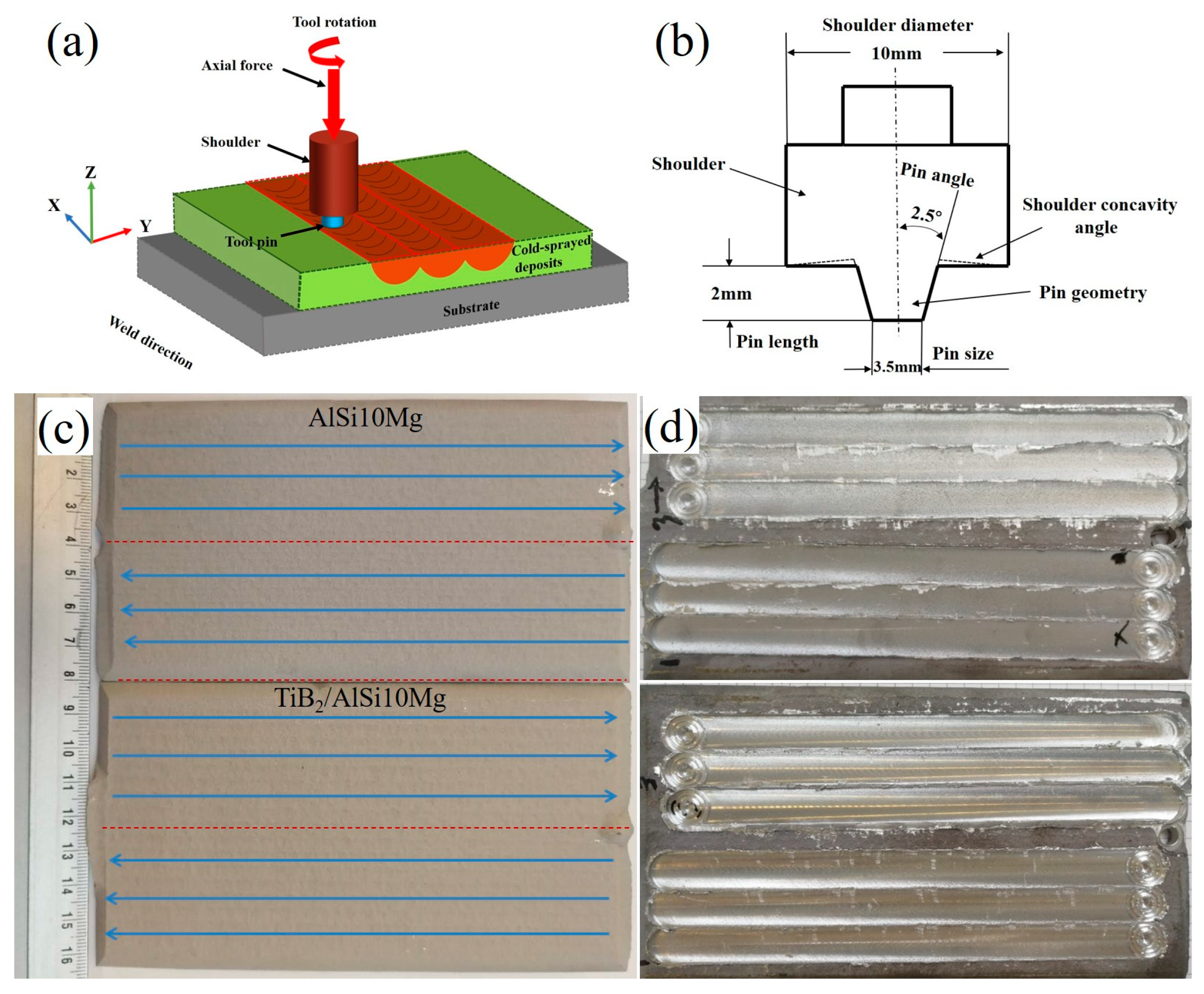
2.2. Post-FSP Treatment

The post-FSP treatment was performed on the CS AlSi10Mg+TiB2 composite coatings using two different passes (1 and 3 passes). The schematic diagram of the post-FSP treatment of cold-sprayed deposits is shown in Figure 2a. This study employed a commercial friction stir welding (FSW) machine (FSW-RL31-010, Beijing FSW Technology Co., Ltd., Beijing, China). As illustrated in Figure 1b, an H13 steel stir tool with a threaded pin (3.5 mm root diameter and 2.0 mm length) and a concave shoulder (10 mm diameter) was utilized. The tool was positioned at a 2.5° tilt angle to prevent surface defects. The rotation direction was set to anticlockwise, with a rotation speed of 1500 rpm and a traverse speed of 500 mm/min for each pass. The pin and shoulder movement strategies as well as the coating morphology before and after FSP treatment are presented in Figure 2c,d.

2.3. Microstructure Characterization

The deposition efficiency (DE) of the CS process was calculated by measuring the weights of the substrate ( W 1 ), feedstock powder ( W 2 ), substrate with coating ( W 3 ), and the left-over feedstock powder ( W 4 ) according to Equation (1):
D E = W 3 W 1 W 2 W 4 × 100 %
An optical microscope (OM) (Nikon, Tokyo, Japan) was employed to examine the microstructures of the powder and coatings. The porosity of the coatings was quantified using ImageJ 1.8.0 software. For cross-sectional microstructure analysis, specimens were polished and etched at room temperature with Kroll’s reagent (3 mL HF + 6 mL HNO3 + 100 mL H2O). The polished samples as well as the surface morphologies were observed by an SEM instrument (JSM5800LV, JEOL, Tokyo, Japan), equipped with an EDS unit. The TiB2 particle size distribution and volume fraction in the as-deposited coatings were analyzed using ImageJ software, based on SEM images. Flattening ratio measurements for the initial powders and deposits were conducted on a minimum of 35 particles per sample. TEM characterization was performed using an FEI Tecnai G2 microscope (Hillsboro, OR, USA) operating at 200 kV. TEM samples were first mechanically polished and then subjected to ion milling using a Gatan Model 691 (Pleasanton, CA, USA) precision ion polishing system.

2.4. Microhardness and Tribological Test

Microhardness was measured using a Vickers hardness indenter (Leitz, Wetzlar, Germany) with a load of 100 N and a duration of 15 s. The microhardness measurement of the powder was conducted on the polished cross-section of large particles using a load of 15 N. Ten positions were randomly tested on the polished cross-sections to have an average value for each sample. In addition, to obtain the distribution of the microhardness value in the FSP-treated AlSi10Mg and AlSi10Mg+TiB2 samples, tests were conducted at an interval of 500 µm between indentation points.
Dry sliding wear tests were performed at an ambient temperature using a CSEM tribometer implement (Neuchâtel, Switzerland). Dry sliding wear tests were performed at ambient temperature using a CSEM tribometer (Switzerland). Prior to testing, the sample surfaces were polished to achieve a roughness below 0.05 μm, with final polishing conducted using a 0.05 μm Al2O3 solution. A cleaned 6 mm diameter Al2O3 ball served as the counterpart material under a 2 N load. A linear rotation speed of 10 cm/min and a rotation radius of 4 mm were used during the test. The friction coefficient was recorded over a sliding distance of 300 m. Following the test, worn sample surfaces were examined via SEM and EDS. Wear rates were determined based on cross-sectional profiles of the worn tracks measured with an Altisurf 500 profilometer (Marin, France). Worn volumes were calculated by multiplying the cross-sectional areas by the track lengths. To assess wear resistance, the wear rate was defined as the worn volume per unit of normal load and sliding distance, as described by the formula below [25]:
ω = 2 π r S p l
where ω represents the wear rate in mm3/(N·m), r is the wear radius in mm, S is the cross-sectional area in mm2, p is the normal load in N, and l is the sliding distance in m.

3. Results and Discussion

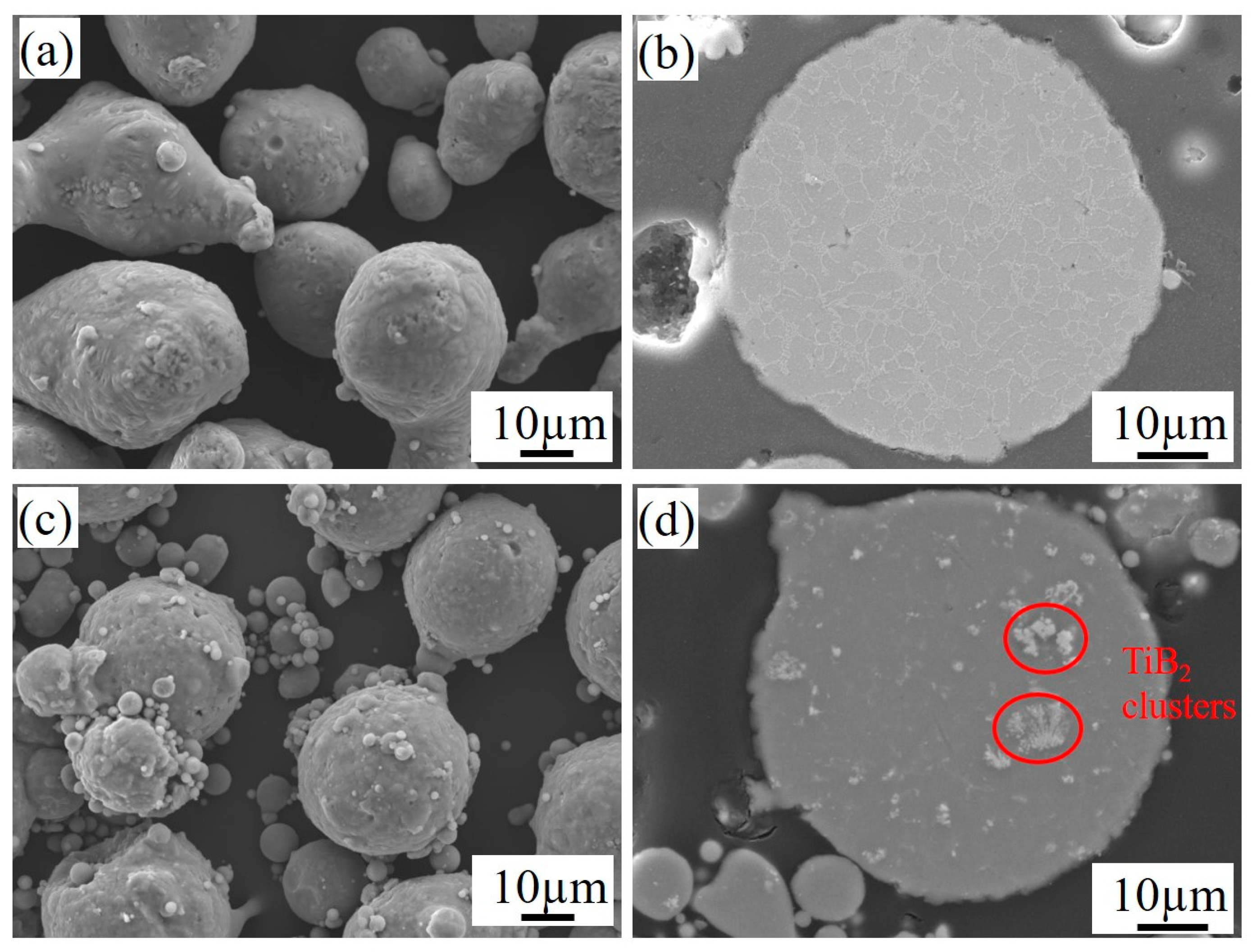
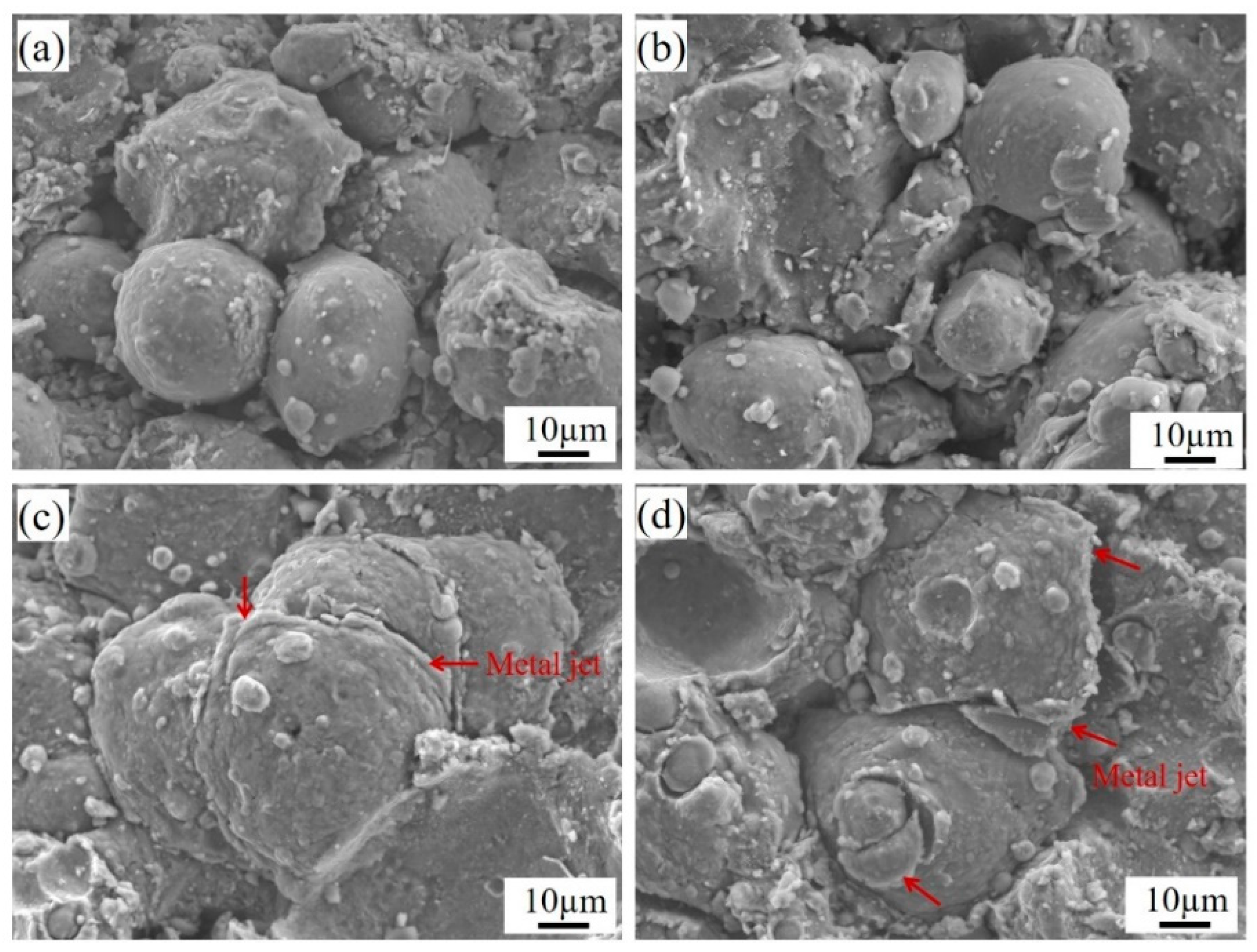
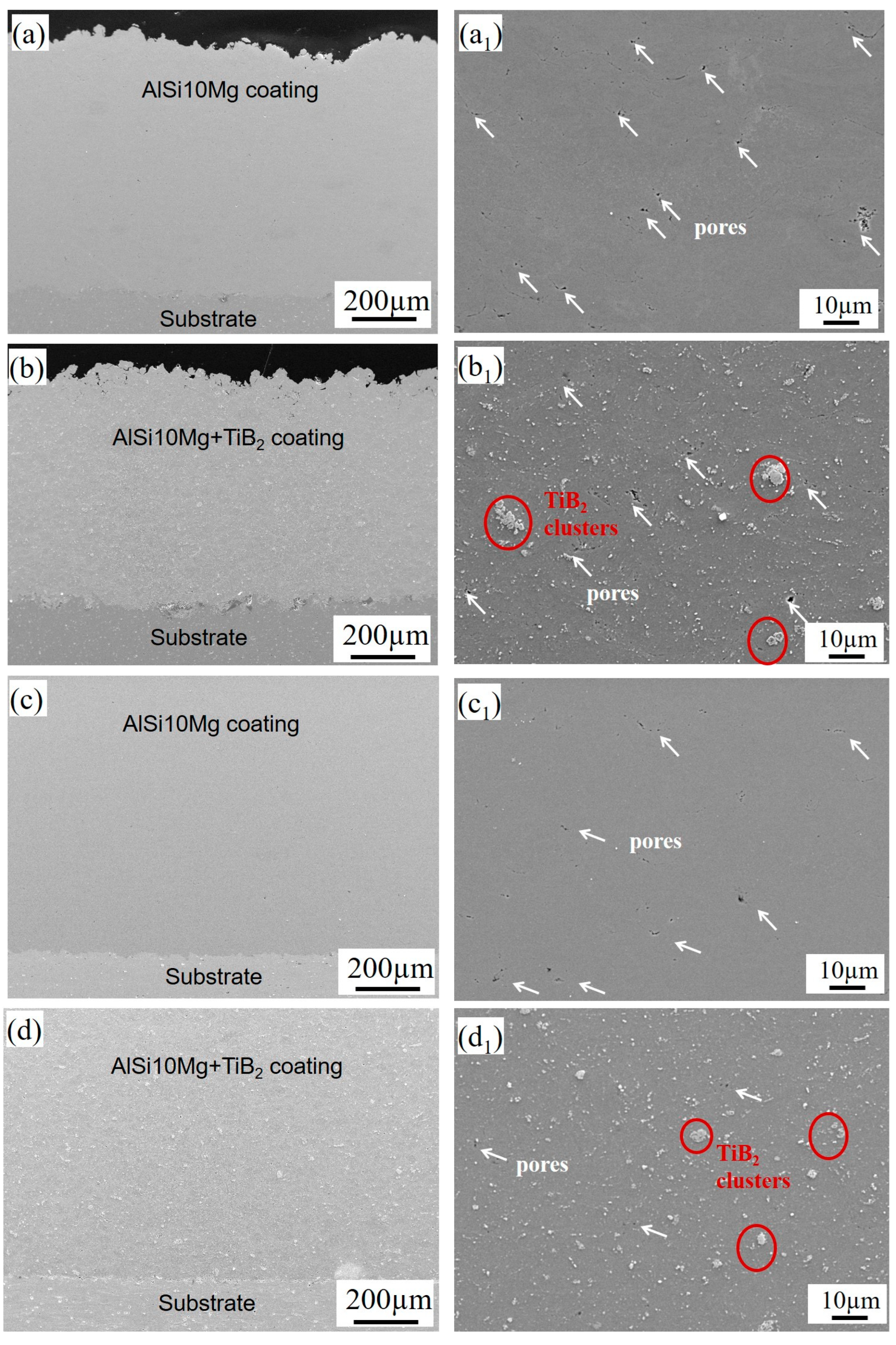
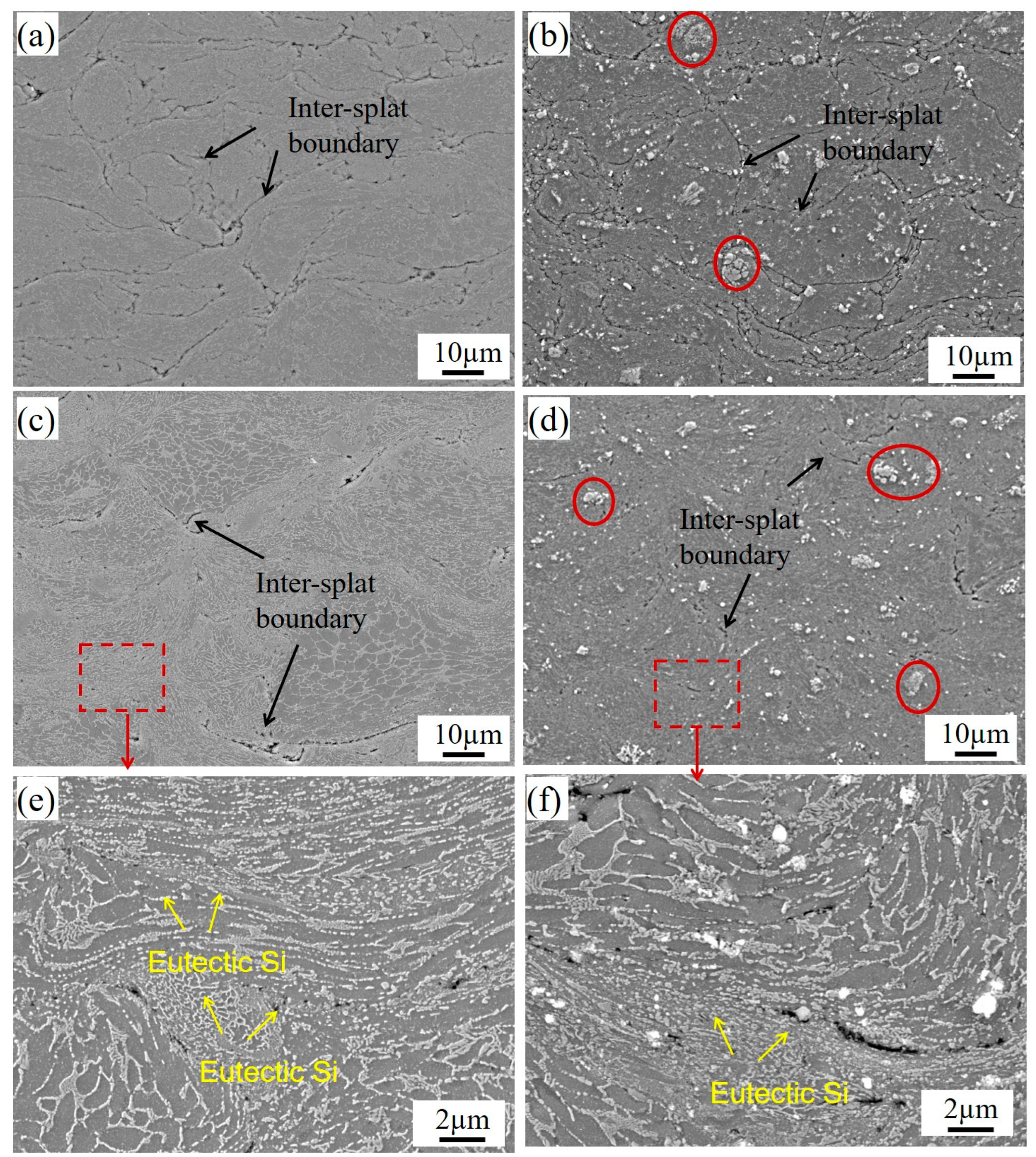
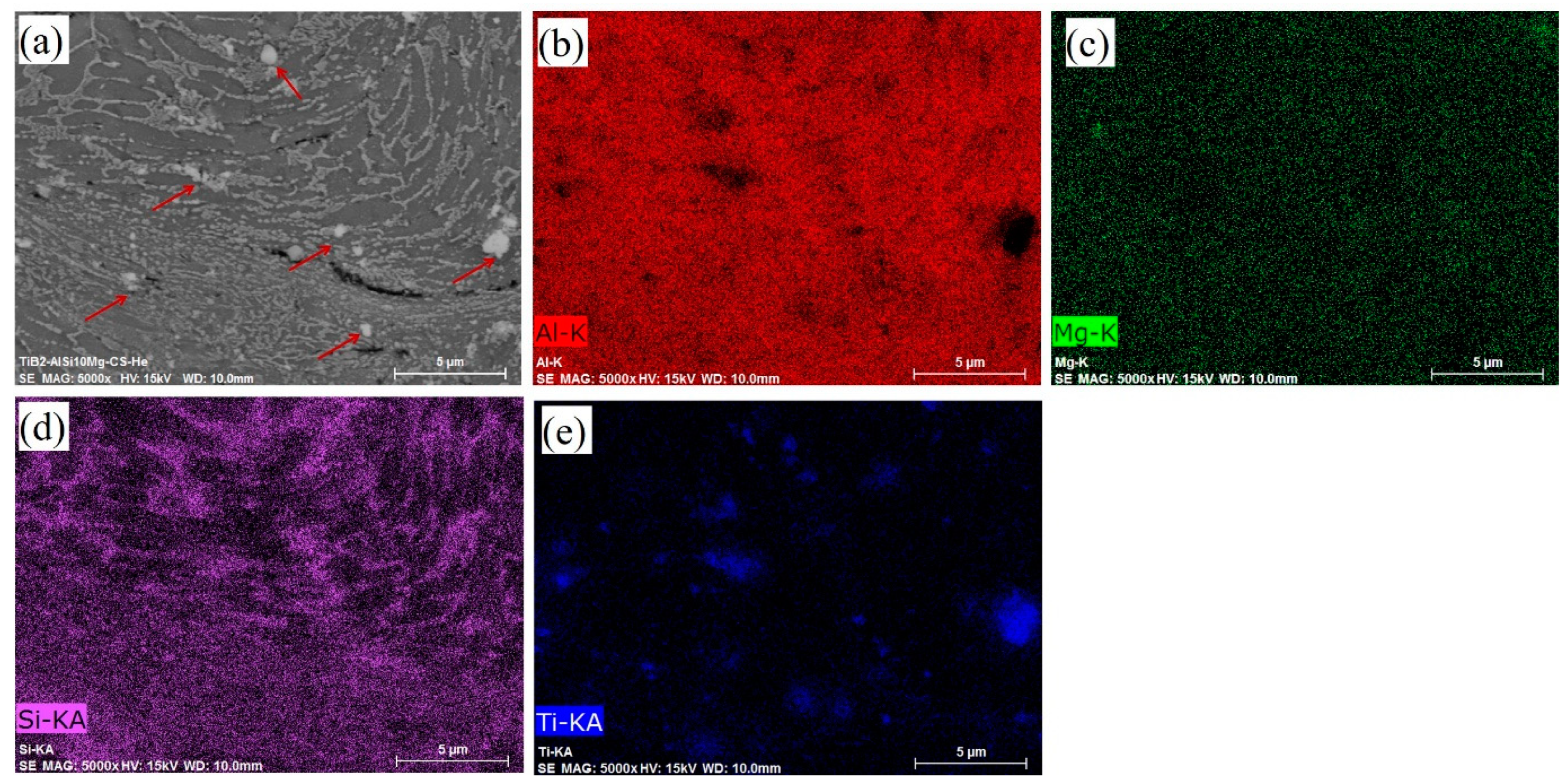
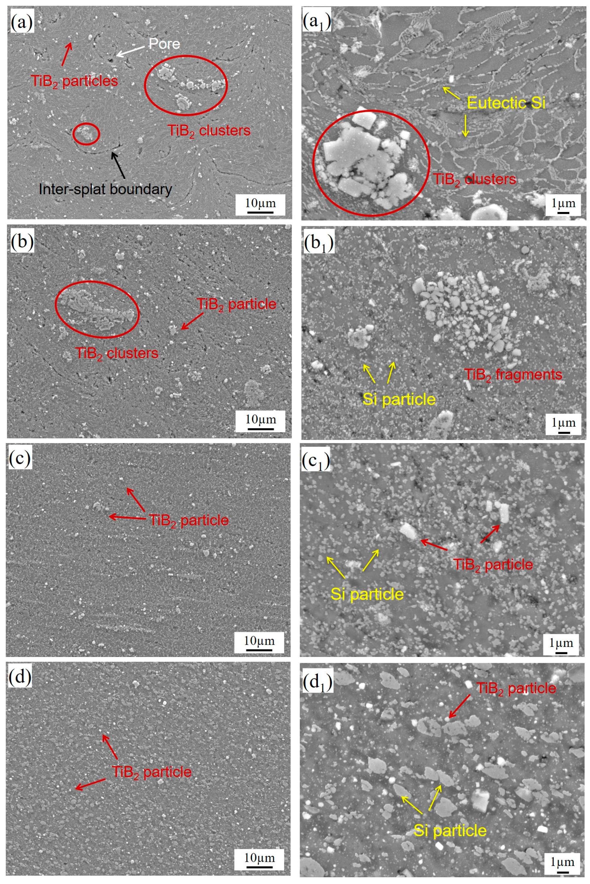
3.1. Microstructure Characterization of As-Deposited Deposits

Figure 3 shows the surface morphologies of the CS AlSi10Mg and AlSi10Mg+TiB2 composite deposits using varying processing conditions. The morphologies exhibit different deposition features for different processing conditions. Here, the deposits prepared under the CT1 (Pg = 3.0 MPa, Tg = 470 °C, compressed air) and CT2 (Pg = 1.8 MPa, Tg = 320 °C, helium) conditions were denoted as AlSi10Mg-CT1, AlSi10Mg+TiB2-CT1, AlSi10Mg-CT2, and AlSi10Mg+TiB2-CT2. Regarding the CT1 deposits, as shown in Figure 3a,b, the particles at the top layer exhibit spherical or quasi-spherical morphologies, suggesting minimal plastic deformation during the deposition process. However, in the case of the CT2 deposits, when He was used as the propellant gas, both the pure AlSi10Mg and AlSi10Mg+TiB2 composite particles underwent significant plastic deformation, with a prominent metal jet observed at the edges of the deformed splats (Figure 3c,d). CFD modeling of the particle velocity and temperature during the CS process was conducted using Fluent/Ansys software 2021 R1. The simulation results reveal that the average particle velocities for the pure AlSi10Mg powder and AlSi10Mg+TiB2 composite powder in CT2 are about 820 m/s and 816 m/s, respectively, which are much higher than those obtained from CT1 (654 m/s and 646 m/s for the pure AlSi10Mg powder and AlSi10Mg+TiB2 composite powder, respectively). Therefore, the use of He as the propellant gas results in a substantially higher particle impact velocity, promoting intensive plastic deformation and enhancing metallic bonding between the deformed splats.
Figure 4 shows the cross-sectional micrographs of the pure AlSi10Mg and AlSi10Mg+TiB2 composite deposits. Thick and dense deposits were successfully fabricated by CS. In addition, Figure 4c,d reveal that the deposits are well bonded with the Al substrates without any cracks or gaps. The magnified views of the deposits are shown in Figure 4a1–d1. A few small pores with a size less than 2 µm can be observed on the polished surface of the CT1 deposits. The porosity measurements based on five SEM images using the ImageJ software show that the porosity values of the pure AlSi10Mg and AlSi10Mg+TiB2 composite deposits in CT1 are about 0.68 and 0.45, respectively; the CT2 deposits have much lower values of approximately 0.35 and 0.24 for the pure AlSi10Mg and AlSi10Mg+TiB2 composite deposits, respectively. It is well understood that a much higher particle velocity in CT2 can result in greater plastic deformation of the particles and thus, denser structures. It is also interesting to note that the composite deposits possess lower porosities than the pure AlSi10Mg deposits in both the CT1 and CT2 conditions. The increased density of the composite deposit is attributed to the intensified in situ hammering effect caused by rebounding particles during CS deposition. Additionally, the addition of TiB2 particles into the AlSi10Mg matrix strengthens the composite. The microhardness measurements on the cross-section showed that the AlSi10Mg+TiB2 composite powder had an average value of 68 HV0.015, significantly higher than the AlSi10Mg powder without reinforcements (52 HV0.015). As a result, a higher critical impact velocity is necessary for the successful deposition of the composite particles. Particles with velocities below this threshold fail to adhere and rebound from the surface. Furthermore, TiB2 particles on the composite surface may act as contaminants, similar to oxides, impeding metallic bonding between splats during deposition. These factors collectively result in a larger number of particles rebounding from the coating surface due to deposition failure. These rebounded particles work as in situ peening particles, which can further deform the previously deposited layers [26,27]. Consequently, a slightly denser structure was obtained for the composite deposits. As indicated by the EDS mapping (see Figure 5 and Figure 6), these white ultrafine particles marked by red arrows are the TiB2 phase. It can be observed in Figure 4b1,d1 that the ultrafine TiB2 particles are uniformly dispersed across the composite deposits. Meanwhile, some micron-sized TiB2 clusters can also be observed. The TiB2 particles have a size distribution from 100 nm to 8 µm, with the majority being smaller than 700 nm. An analysis of five SEM images reveals that the volume fraction of the TiB2 particles in the composite deposits is approximately 4.4 vol.%.
Figure 5 shows the SEM micrographs of the etched cross-sections of the cold-sprayed deposits. In the lower-magnification views (Figure 5a,b), significant deformation of AlSi10Mg particles during deposition is evident, resulting in a dense structure. Nevertheless, poorly bonded inter-splat boundaries and small pores at these boundaries are still noticeable. Comparatively, the particles within the CT2 deposits experienced much greater deformation, resulting in a larger flattening ratio compared to those in the CT1 deposits. However, there are still some poor bonding inter-splat interfaces that can be observed within the CT2 deposits. The higher magnified SEM views and the EDS mapping of the CT2 deposits are shown in Figure 5e,f and Figure 6. A gray primary α-Al matrix decorated with a white fibrous Si network can be observed in both the as-deposited pure AlSi10Mg and AlSi10Mg+TiB2 composite deposits, which is similar to the structure of the initial powder. Some of the fibrous Si network was heavily deformed in some regions, resulting in the formation of linear arrayed ultrafine Si particles, especially near the inter-splat boundaries. These ultrafine Si particles are finely dispersed in the Al matrix, positively influencing the mechanical properties of the as-deposited samples.

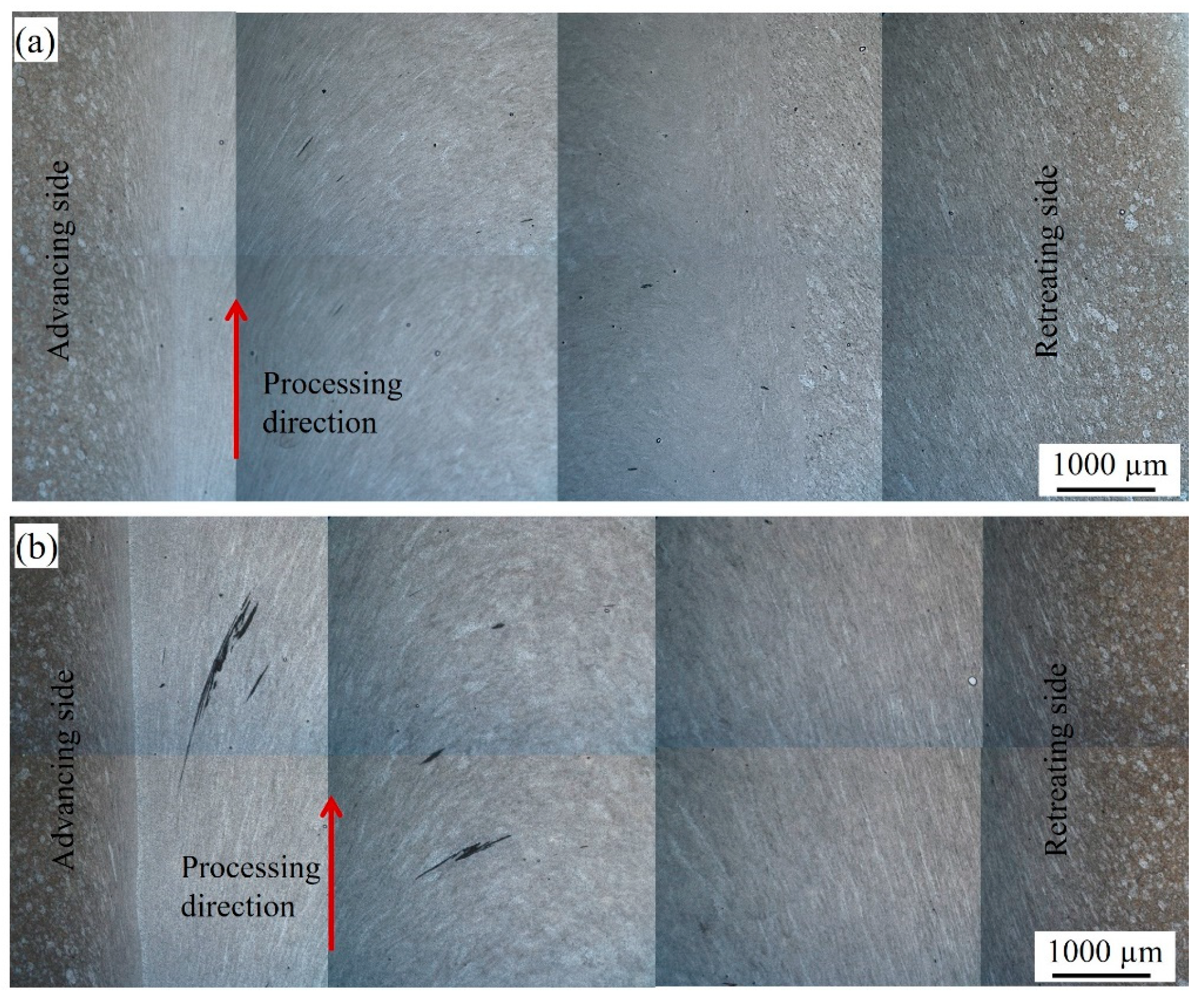
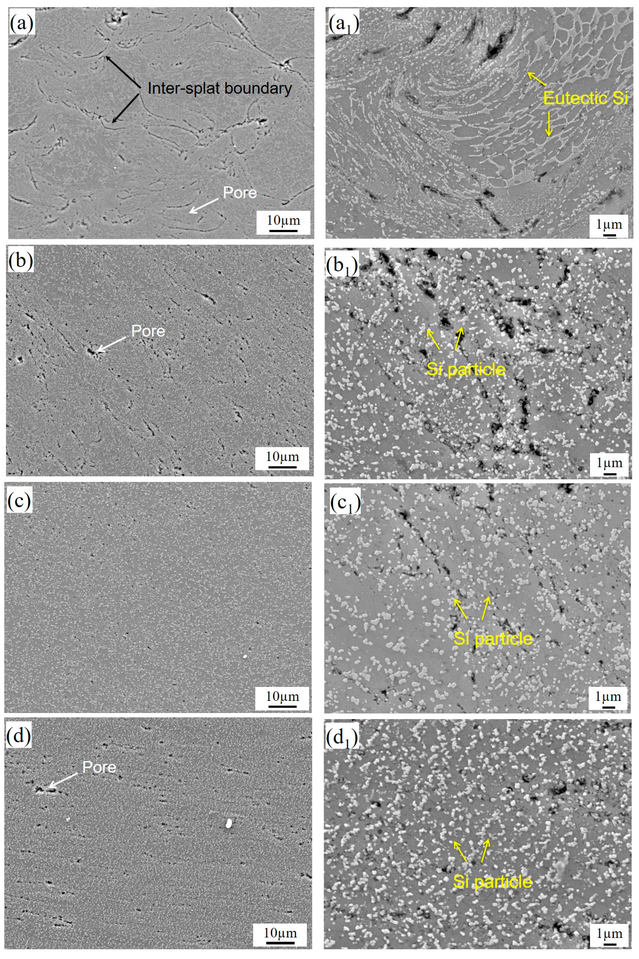
3.2. Microstructure Characterization After Post-FSP Treatment

Figure 7a,b display the etched cross-sectional overviews of the CS AlSi10Mg deposits after one pass and three passes of FSP treatments, respectively. The SZ appears as a half-basin shape. This nugget zone is free of defects such as keyholes, cracks, or tunnels. A sharp boundary is visible between the SZ and the unprocessed as-deposited deposits. On the contrary, the boundary on the retreating side is obscure. A similar observation can be found on the surface morphologies, as illustrated in Figure 8. Some whiter regions appear on the top, right, and bottom of the SZ, where the materials undergo greater plastic deformation and the thermal effect. Moreover, such a white region also appears in the center of the SZ after three passes of the FSP treatment. As shown in Figure 7c,d, a similar morphology evolution can also be observed in the FSP-treated AlSi10Mg+TiB2 composite deposits. However, a part of the composite deposit was stirred into the substrate, especially for the composite deposit after the multi-FSP treatment. This is because the composite deposits are about 0.5 mm thinner and the press amount of the pin was not well controlled during the FSP operation.
To evaluate the influence of the post-FSP treatment on the microstructure evolution of the cold-sprayed deposits, SEM images were taken of different regions of the cross-section of the deposit after the FSP treatment. As marked in Figure 9, regions A to C represent the heat-affected zone (HAZ), thermomechanical-affected zone (TMAZ), and SZ, respectively, while region D is at the bottom of the stir zone. As shown in Figure 9a, evident inter-splat boundaries and small pores can be seen in the HAZ. Figure 9b shows a typical morphology of the TMAZ, where the inter-splat boundaries tend to disappear. However, some small pores are still present along the material flow direction. As shown in the magnified SEM image (Figure 9b1), eutectic Si networks are broken into ultrafine individual Si particles in this region. The SZ is characterized by a dense structure with uniformly distributed Si particles (Figure 9c1). The average particle size of the Si phase was measured as approximately 0.42 µm, showing slight growth compared to that of the as-deposited state. Figure 10 shows the microstructure of the AlSi10Mg deposit after repeating the FSP treatment for three passes. The Si particles within the SZ become larger, and their number and density decrease significantly. This phenomenon is more evident in the whiter regions, as shown in Figure 10c. The coarsening of the Si phase observed in SZ is similar to the annealing heat treatment effect, as the deposits experienced extensive plastic deformation and a large amount of heat was generated during the FSP process, especially in the case of three passes. Indeed, it was reported that the temperature in the SZ can reach as high as 400–480 °C [28].
The post-FSP-treated AlSi10Mg+TiB2 composites show a similar evolution in the inter-splat boundary and Si phase (Figure 11). Interestingly, the TiB2 clusters presented in the as-deposited composite deposits are broken into smaller-sized particles after the FSP treatment. As shown in Figure 11c, the remarkably refined TiB2 particles are uniformly dispersed in the SZ. The finer distribution is attributed to the vigorous stirring action of the rotating tool, which forces the particles into the grains. The reduced segregation or particle clustering is evident in Figure 11c,d. Similar fragmentation of SiC and Al2O3 particles has also been reported in studies on the FSP of aluminum matrix composites (AMCs) [29,30]. However, a few TiB2 clusters can still be observed in the TMAZ, as the effect of the shear force in this zone is not strong enough to redistribute the particles. By examining five SEM images for each case, the volume fractions of the TiB2 particles in the CS and post-FSP-treated composites were counted. The volume fraction of the TiB2 particles in the post-FSP-treated composite yields an average value of 3.8 vol.%, slightly lower than that of the as-deposited state (4.1 vol.%). The decrease is because some nanosized TiB2 particles (less than 200 nm) cannot be counted by using this method. However, these refined and uniformly distributed TiB2 particles play an important role in enhancing the mechanical properties of the composite.
TEM micrographs of the CS and post-FSP-treated AlSi10Mg+TiB2-CT2 composite samples are presented in Figure 12. As shown in Figure 12a, the as-deposited composite microstructure is characterized by equiaxed grains, which is indicative of the interior particle region. These equiaxed grains have an average size of about 450 nm. However, it should be noted that the grain size in the highly deformed region could be much smaller. A large number of Si nanoparticles, marked by yellow arrows, are dispersed into the Al matrix. The magnified micrograph in Figure 12b shows that these Si particles are less than 50 nm, and most of them are located at the GBs. In addition, as highlighted by the red arrows, the TiB2 particles are almost cubic or polyhedral in morphology with the size ranging from several tens to several hundreds of nanometers. The TiB2 particles are predominantly located along the GBs. In the interior particle region, the lack of dislocations inside the Al grains seems to indicate that the dislocation density in the initial composite deposit is low.
After the FSP treatment, the composite sample is characterized by fine equiaxed Al grains, measuring 250–350 nm, as shown in Figure 12c. These fine grains form due to intense plastic deformation and subsequent dynamic recrystallization. The strain rate at the interface between the tool pin and the material reaches approximately 80 s⁻1, significantly exceeding the typical values for conventional deformation methods (0.1–10 s⁻1) [29,31]. This high strain rate promotes effective grain refinement. The strain rate of this magnitude contributes to grain refinement. As highlighted in Figure 12d, after the FSP treatment, the Si nanoparticles, as well as the TiB2 nanoparticles, are distributed not only along the GBs but also inside the Al grains. It is well understood that eutectic Si can be rejected from the supersaturated Al matrix to form small Si particles due to the thermal softening effect as a result of the friction between the working tool and the material surface. The FSP-treated sample revealed a slight growth of Si particles compared to the as-deposited state. In addition, it can be noted that the nanosized TiB2 particles are mainly distributed at the GBs of the Al matrix in the as-deposited state. However, the uniform distribution of the TiB2 particles is observed after the post-FSP treatment. The finer distribution is attributed to the intense stirring action of the rotating tool, which forced the TiB2 particles into the grains [29]. These uniformly distributed TiB2 nanoparticles tend to restrict the dynamic recrystallization and slow down grain growth via pinning the movement of GBs and sub-boundaries.

3.3. Microhardness Evolution

Figure 13 shows the microhardness values measured on a horizontal line across the cross-section of the post-FSP-treated samples. The microhardness evolution for the post-FSP-treated samples can be divided into three typical zones: the HAZ, TMAZ, and SZ. A continuous decrease in microhardness can be observed from the unaffected region to the HAZ, TMAZ, and finally SZ, with the lowest values. The asymmetry of microhardness in the advancing side and the reversing side is because the microstructure on the reversing side was influenced by the following FSP path, while the advancing side was free of other FSP paths. Therefore, the microhardness on the advancing side is much higher and close to the bulk value (176 HV0.1). The removal of the work-hardening effect is the primary factor that should be responsible for such a significant decrease in microhardness in the HAZ, TMAZ, and SZ regions. In addition, it can be noted that in the same position for these zones, the multi-pass-treated samples possess slightly lower values compared to the single-pass-treated samples, which suggests that more thermal effect was produced after three passes of the FSP treatment. The high heat in the HAZ region altered the matrix properties by promoting softening, which is attributed to the coarsening of Si precipitates and an increase in the grain size. Increasing the FSP passes results in lower microhardness. Moreover, the microhardness of the composite deposits in the SZ is approximately 110 ± 3 HV0.1, which is higher than that of the pure AlSi10Mg deposit (87 HV0.1) due to the presence of TiB2 nanoparticles. This fact may result from the combined effect of grain refinement and the reinforcement of TiB2 particles, which may offset a part of the softening effect due to Si phase coarsening in the SZ region.

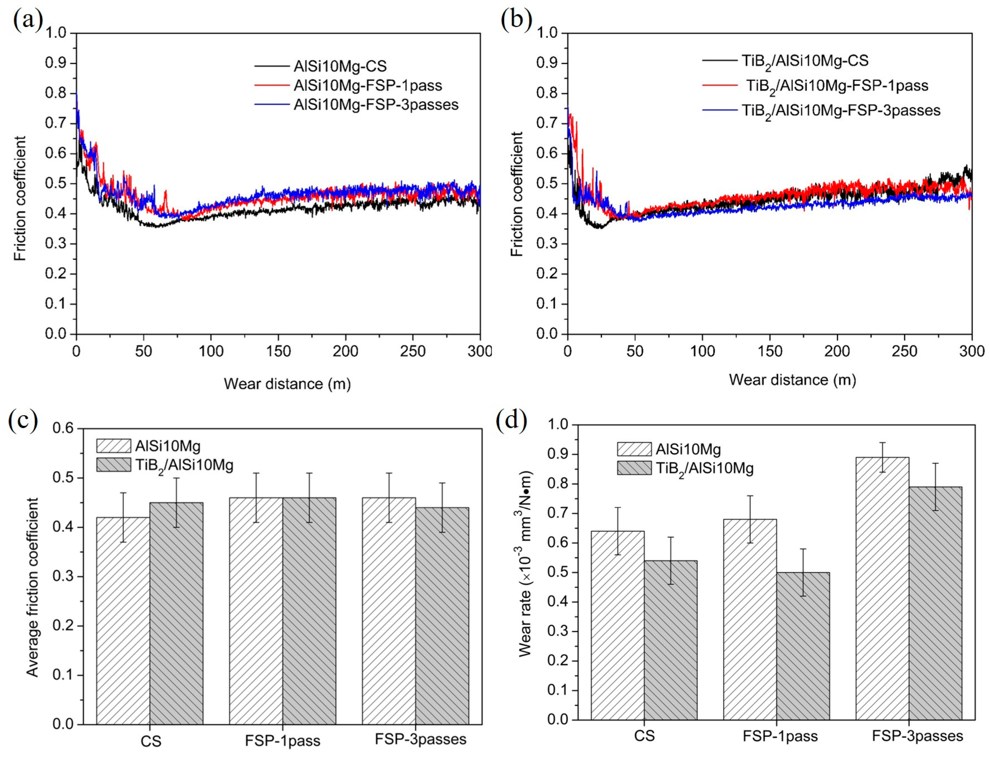
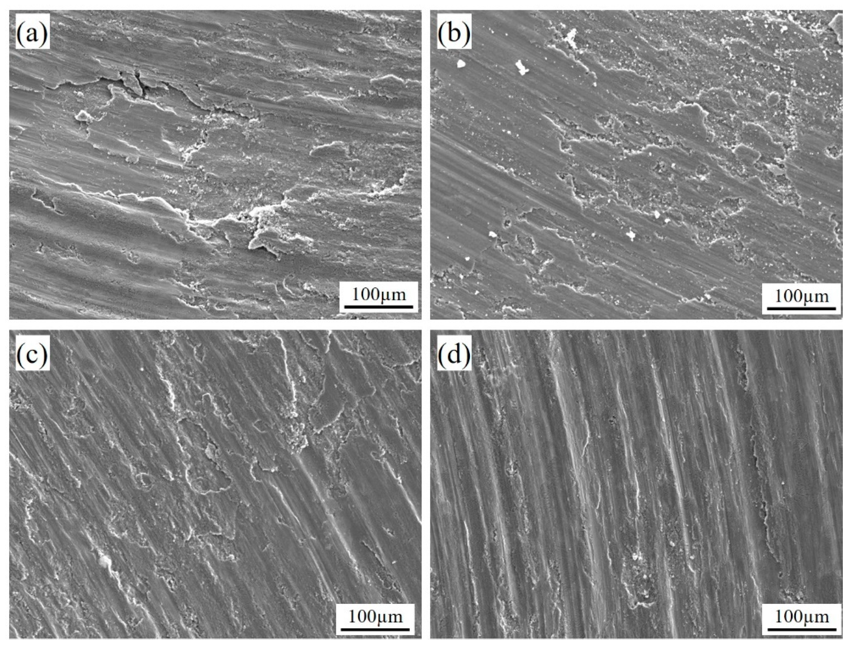
3.4. Wear Properties

The tribological performance of the AlSi10Mg-CT2 and AlSi10Mg+TiB2-CT2 composite deposits before and after the FSP treatment is presented in Figure 14. As illustrated in Figure 14a,b, the COFs of both deposits show an unstable initial state (run-in), which then becomes steady after about 80 m and 50 m sliding distance for the pure AlSi10Mg and TiB2 reinforced composite deposits, respectively. This observation again indicates that adding TiB2 particles is beneficial for the formation of tribofilm, reaching a stable stage earlier than the unreinforced AlSi10Mg deposits. A sharp increase in the COF at the final stage observed in the AlSi10Mg-CT1 deposit is absent in the case of the CT2 deposits, which suggests a better inter-splat bonding state for the CT2 deposits. In addition, the CT2 deposits possess lower COF values and a reduced wear rate than the CT1 deposits. This could mainly be due to the enhanced microhardness and improved inter-splat bonding. Generally, the AlSi10Mg+TiB2 composite deposits exhibit better wear performance compared to the unreinforced AlSi10Mg deposits.
The FSP treatment seems to have little effect on the wear performance for both the pure AlSi10Mg and AlSi10Mg+TiB2 composite samples, as the COF values and wear rates remain essentially unchanged after the FSP treatments. In general, a significant decrease in the microhardness after FSP treatment can result in a higher wear rate. However, the elimination of defects and precipitation of Si particles after the FSP treatment may improve the wear performance of the post-FSP-treated samples. As for the AlSi10Mg+TiB2 composite samples, the redistribution and refinement of TiB2 particles are also beneficial for the improvement of the wear performance. The worn surface of the as-deposited AlSi10Mg deposit, shown in Figure 15a,b, exhibits typical adhesive wear features. The wear track profiles reveal evidence of material plowing and extrusion outside the wear track, along with the presence of loose wear debris and delamination. Due to the relatively weak interparticle bonding in the cases of the as-sprayed samples, cracks formed on the worn track surface because of localized weakening under normal and tangential loading. These initiated cracks will propagate at the surface along the sliding direction, which leads directly to the observed wear flakes and delamination. After the FSP treatment, the metallurgical bonding between the deformed particles was significantly improved, which may have reduced crack formation. The wear track on the composite deposit surface had a relatively narrow width, shallow plowing grooves, and less debris compared to the pure AlSi10Mg deposits. It is difficult to plow the wear debris from the matrix because the attachment of the TiB2 particles in the matrix is improved with the in situ reaction process. Additionally, TiB2 particles carry a portion of the applied load and prevent the plastic deformation of the surface. Therefore, we may conclude that both the bonding conditions and microhardness are detrimental to the wear performance of the deposits.

4. Conclusions

This study investigates the influence of FSP on the microstructure, microhardness, and tribological properties of the cold-sprayed AlSi10Mg+TiB2 composite coatings on Al substrates. The main conclusions can be drawn as follows:
Due to the limitation of particle deformation during CS, there were still some porosities and poorly bonded regions in the as-deposited pure AlSi10Mg and AlSi10Mg+TiB2 composite coatings, even though He was used as the propellant gas.
Applying FSP to the composite coating significantly reduced the porosity and improved the metallurgical bonding. In addition, both the distribution of the TiB2 particles and the microstructure of the composite coating were homogenized as a result of the severe plastic deformation of the material during the FSP process.
A continuous decrease in the microhardness can be observed from the unaffected region to the heat-affected zone, thermomechanical-affected zone, and finally the stir zone, with the lowest values. The decreased microhardness is primarily attributed to the removal of the work-hardening effect.
FSP treatment seems to have little impact on the wear performance for both the pure AlSi10Mg and AlSi10Mg+TiB2 composite samples, as the coefficient of friction values and wear rates remain essentially unchanged after the FSP treatments.

Author Contributions

Methodology, Y.J. and R.L.; Investigation, Y.J.; Writing—review & editing, X.X. All authors have read and agreed to the published version of the manuscript.

Funding

The authors appreciate the financial support from the National Science Foundation of China (Grant No. 52204390), the Natural Science Foundation of Jiangsu Province (Grant Nos. BK20231274, BK20232025), and the Priority Academic Program Development of Jiangsu Higher Education Institutions (PAPD).

Institutional Review Board Statement

Not applicable.

Informed Consent Statement

Not applicable.

Data Availability Statement

Data are contained within the article.

Conflicts of Interest

The authors declare no conflict of interest.

References

  1. Li, W.; Yang, K.; Yin, S.; Yang, X.; Xu, Y.; Lupoi, R. Solid-state additive manufacturing and repairing by cold spraying: A review. J. Mater. Sci. Technol. 2018, 34, 440–457. [Google Scholar] [CrossRef]
  2. Schmidt, T.; Gärtner, F.; Assadi, H.; Kreye, H. Development of a generalized parameter window for cold spray deposition. Acta Mater. 2006, 54, 729–742. [Google Scholar] [CrossRef]
  3. Zou, Y. Cold Spray Additive Manufacturing: Microstructure Evolution and Bonding Features. Acc. Mater. Res. 2021, 2, 1071–1081. [Google Scholar] [CrossRef]
  4. Assadi, H.; Gärtner, F.; Stoltenhoff, T.; Kreye, H. Bonding mechanism in cold gas spraying. Acta Mater. 2003, 51, 4379–4394. [Google Scholar] [CrossRef]
  5. Klinkov, S.V.; Kosarev, V.F.; Rein, M. Cold spray deposition: Significance of particle impact phenomena. Aerosp. Sci. Technol. 2005, 9, 582–591. [Google Scholar] [CrossRef]
  6. Dewar, M.P.; McDonald, A.G.; Gerlich, A.P. Interfacial heating during low-pressure cold-gas dynamic spraying of aluminum coatings. J. Mater. Sci. 2011, 47, 184–198. [Google Scholar] [CrossRef]
  7. Assadi, H.; Kreye, H.; Gärtner, F.; Klassen, T. Cold spraying—A materials perspective. Acta Mater. 2016, 116, 382–407. [Google Scholar] [CrossRef]
  8. Yin, S.; Fan, N.; Huang, C.; Xie, Y.; Zhang, C.; Lupoi, R.; Li, W. Towards high-strength cold spray additive manufactured metals: Methods, mechanisms, and properties. J. Mater. Sci. Technol. 2024, 170, 47–64. [Google Scholar] [CrossRef]
  9. Borchers, C.; Gärtner, F.; Stoltenhoff, T.; Kreye, H. Microstructural bonding features of cold sprayed face centered cubic metals. J. Appl. Phys. 2004, 96, 4288–4292. [Google Scholar] [CrossRef]
  10. Grujicic, M.; Saylor, J.R.; Beasley, D.E.; DeRosset, W.S.; Helfritch, D. Computational analysis of the interfacial bonding between feed-powder particles and the substrate in the cold-gas dynamic-spray process. Appl. Surf. Sci. 2003, 219, 211–227. [Google Scholar] [CrossRef]
  11. Xie, Y.; Yin, S.; Chen, C.; Planche, M.-P.; Liao, H.; Lupoi, R. New insights into the coating/substrate interfacial bonding mechanism in cold spray. Scr. Mater. 2016, 125, 1–4. [Google Scholar] [CrossRef]
  12. Cavaliere, P.; Silvello, A. Fatigue behaviour of cold sprayed metals and alloys: Critical review. Surf. Eng. 2016, 32, 631–640. [Google Scholar] [CrossRef]
  13. Maharjan, N.; Ramesh, T.; Pham, D.Q.; Zhai, W.; Ang, A.; Zhou, W. Post-processing of cold sprayed Ti6Al4V coating by laser shock peening. J. Mater. Process. Technol. 2024, 330, 118461. [Google Scholar] [CrossRef]
  14. Judas, J.; Zapletal, J.; Adam, O.; Řehořek, L.; Jan, V. Microstructural stability and precipitate evolution of thermally treated 7075 aluminum alloy fabricated by cold spray. Mater. Charact. 2024, 216, 114259. [Google Scholar] [CrossRef]
  15. Kromer, S.C.R.; Verdy, C.; Gojon, S.; Liao, H. Laser surface texturing to enhance adhesion bond strength of spray coatings—Cold spraying, wire-arc spraying, and atmospheric plasma spraying. Surf. Coat. Technol. 2018, 352, 642–653. [Google Scholar] [CrossRef]
  16. Shtansky, D.V.; Batenina, I.V.; Yadroitsev, I.A.; Ryashin, N.S.; Kiryukhantsev-Korneev, P.V.; Kudryashov, A.E.; Sheveyko, A.N.; Zhitnyak, I.Y.; Gloushankova, N.A.; Smurov, I.Y.; et al. A new combined approach to metal-ceramic implants with controllable surface topography, chemistry, blind porosity, and wettability. Surf. Coat. Technol. 2012, 208, 14–23. [Google Scholar] [CrossRef]
  17. Wang, W.; Han, P.; Wang, Y.; Zhang, T.; Peng, P.; Qiao, K.; Wang, Z.; Liu, Z.; Wang, K. High-performance bulk pure Al prepared through cold spray-friction stir processing composite additive manufacturing. J. Mater. Res. Technol. 2020, 9, 9073–9079. [Google Scholar] [CrossRef]
  18. Liu, Z.-H.; Han, P.; Wang, W.; Guan, X.-H.; Wang, Z.; Fang, Y.; Qiao, K.; Ye, D.-M.; Cai, J.; Xie, Y.-C.; et al. Microstructure; mechanical properties, and corrosion behavior of 6061Al alloy prepared by cold spray-friction stir processing composite additive manufacturing. Trans. Nonferrous Met. Soc. China 2023, 33, 3250–3265. [Google Scholar] [CrossRef]
  19. Yang, Z.; Wang, J.; Li, X.; Wang, Y.; Ni, D.; Zhang, X.; Xu, J.; Li, M. Improving the mechanical properties and electrical conductivity of cold-sprayed Cu-Ti3SiC2 composite by friction stir processing. Compos. Part A Appl. Sci. Manuf. 2023, 173, 107698. [Google Scholar] [CrossRef]
  20. Hodder, K.J.; Izadi, H.; McDonald, A.G.; Gerlich, A.P. Fabrication of aluminum–alumina metal matrix composites via cold gas dynamic spraying at low pressure followed by friction stir processing. Mater. Sci. Eng. A 2012, 556, 114–121. [Google Scholar] [CrossRef]
  21. Yu, M.; Suo, X.K.; Li, W.Y.; Wang, Y.Y.; Liao, H.L. Microstructure, mechanical property and wear performance of cold sprayed Al5056/SiCp composite coatings: Effect of reinforcement content. Appl. Surf. Sci. 2014, 289, 188–196. [Google Scholar] [CrossRef]
  22. Yang, X.; Li, W.; Yu, S.; Xu, Y.; Hu, K.; Zhao, Y. Electrochemical characterization and microstructure of cold sprayed AA5083/Al2O3 composite coatings. J. Mater. Sci. Technol. 2020, 59, 117–128. [Google Scholar] [CrossRef]
  23. Xie, X.; Chen, C.; Chen, Z.; Addad, A.; Xie, Y.; Wu, H.; Verdy, C.; Wang, Y.; Wang, J.; Ren, Z.; et al. Effect of annealing treatment on microstructure and mechanical properties of cold sprayed TiB2/AlSi10Mg composites. Surf. Interfaces 2021, 26, 101341. [Google Scholar] [CrossRef]
  24. Xie, X.; Ma, Y.; Chen, C.; Ji, G.; Verdy, C.; Wu, H.; Chen, Z.; Yuan, S.; Normand, B.; Yin, S.; et al. Cold spray additive manufacturing of metal matrix composites (MMCs) using a novel nano-TiB2-reinforced 7075Al powder. J. Alloys Compd. 2020, 819, 152962. [Google Scholar] [CrossRef]
  25. Alidokht, S.; Manimunda, P.; Vo, P.; Yue, S.; Chromik, R. Cold spray deposition of a Ni-WC composite coating and its dry sliding wear behavior. Surf. Coat. Technol. 2016, 308, 424–434. [Google Scholar] [CrossRef]
  26. Luo, X.-T.; Wei, Y.-K.; Wang, Y.; Li, C.-J. Microstructure and mechanical property of Ti and Ti6Al4V prepared by an in-situ shot peening assisted cold spraying. Mater. Des. 2015, 85, 527–533. [Google Scholar] [CrossRef]
  27. Xie, X.; Chen, C.; Xie, Y.; Ren, Z.; Aubry, E.; Ji, G.; Liao, H. A novel approach for fabricating Ni-coated FeSiAl soft magnetic composite via cold spraying. J. Alloys Compd. 2018, 749, 523–533. [Google Scholar] [CrossRef]
  28. Rhodes, C.G.; Mahoney, M.W.; Bingel, W.H.; Spurling, R.A.; Bampton, C. Effect of friction stir welding on microtructuer of 7075 Aluminum. Scr. Mater. 1997, 36, 69–75. [Google Scholar] [CrossRef]
  29. Rajan, H.M.; Dinaharan, I.; Ramabalan, S.; Akinlabi, E. Influence of friction stir processing on microstructure and properties of AA7075/TiB2 in situ composite. J. Alloys Compd. 2016, 657, 250–260. [Google Scholar] [CrossRef]
  30. Yang, K.; Li, W.; Niu, P.; Yang, X.; Xu, Y. Cold sprayed AA2024/Al2O3 metal matrix composites improved by friction stir processing: Microstructure characterization, mechanical performance and strengthening mechanisms. J. Alloys Compd. 2018, 736, 115–123. [Google Scholar] [CrossRef]
  31. Mishra, R.S.; McFadden, S.X.; Mara, N.A.; Mukherjee, A.K. High strain rate superplasticity in a friction stir processed 7075 Al alloy. Scr. Mater. 1999, 42, 163–168. [Google Scholar] [CrossRef]
Figure 1. Morphologies of the gas-atomized (a) AlSi10Mg powder and (c) AlSi10Mg+TiB2 composite powder feedstocks. Cross-sectional morphologies of (b) AlSi10Mg powder and (d) AlSi10Mg+TiB2 composite powder.
Coatings 14 01509 g001
Figure 2. (a) Schematic diagrams showing the post-FSP treatment on cold-sprayed deposits and (b) geometry of the stir tool used in this work. Photos of the as-deposited AlSi10Mg and AlSi10Mg+TiB2 composite coating (c) before and (d) after FSP treatment. The blue arrows indicate the stir tool’s movement direction, and the dash lines divide the deposits into two areas (1 pass and 3 passes).
Coatings 14 01509 g002
Figure 3. Surface morphologies of the as-deposited AlSi10Mg and AlSi10Mg+TiB2 deposits obtained from different conditions: (a) AlSi10Mg-CT1; (b) AlSi10Mg+TiB2-CT1; (c) AlSi10Mg-CT2; and (d) AlSi10Mg+TiB2-CT2.
Coatings 14 01509 g003
Figure 4. Cross-sectional morphologies of the CS AlSi10Mg and AlSi10Mg+TiB2 composite deposits at lower magnification: (a) AlSi10Mg-CT1; (b) AlSi10Mg+TiB2-CT1; (c) AlSi10Mg-CT2; and (d) AlSi10Mg+TiB2-CT2. (a1d1) are the magnified views of (ac).
Coatings 14 01509 g004
Figure 5. SEM micrographs of the etched cross-sections of the as-deposited AlSi10Mg and AlSi10Mg+TiB2 composite deposits: (a) AlSi10Mg-CT1; (b) AlSi10Mg+TiB2-CT1; (c) AlSi10Mg-CT2; and (d) AlSi10Mg+TiB2-CT2. (e,f) are the magnified regions marked in (c,d), respectively.
Coatings 14 01509 g005
Figure 6. (a) SEM image and the corresponding EDS mapping of CS AlSi10Mg+TiB2-CT2 deposits: (b) Al; (c) Mg; (d) Si; and (e) Ti. The red arrows indicate the TiB2 particles.
Coatings 14 01509 g006
Figure 7. Optical micrographs showing the cross-section of the post-FSP-treated (a,b) AlSi10Mg deposits and (c,d) AlSi10Mg+TiB2 deposits. (a,c) 1 pass; (b,d) 3 passes.
Coatings 14 01509 g007
Figure 8. Optical micrographs showing the surface morphologies of the post-FSP-treated AlSi10Mg deposits: (a) 1 pass; (b) 3 passes.
Coatings 14 01509 g008
Figure 9. SEM images of the post-FSP-treated AlSi10Mg deposit in different regions corresponding to A, B, C, and D, as marked in Figure 7. (a1d1) Magnified SEM images of the cross-section of the post-FSP-treated AlSi10Mg deposits in different regions corresponding to (ad).
Coatings 14 01509 g009
Figure 10. Magnified SEM images of the post-FSP-treated AlSi10Mg deposits in region E, as marked in Figure 7b. (bd) Magnified images, as marked in (a).
Coatings 14 01509 g010
Figure 11. SEM images of the cross-section of the post-FSP-treated AlSi10Mg+TiB2 deposits in different regions corresponding to F, G, H, and I, as marked in Figure 7c. (a1d1) Magnified SEM images of the cross-section of the post-FSP-treated AlSi10Mg+TiB2 deposits in different regions, corresponding to (ad).
Coatings 14 01509 g011
Figure 12. (a,c) TEM bright-field (BF) images of cold-sprayed and post-FSP-treated AlSi10Mg+TiB2-CT2 composite samples; (b,d) are the magnified views. The red arrows indicate TiB2 particles and the yellow arrows indicate the Si precipitates.
Coatings 14 01509 g012
Figure 13. Microhardness values of post-FSP-treated AlSi10Mg and AlSi10Mg+TiB2 composite samples.
Coatings 14 01509 g013
Figure 14. Friction coefficient vs. sliding wear distance for post-FSP-treated (a) AlSi10Mg-CT2 and (b) AlSi10Mg+TiB2-CT2 composite deposits. (c,d) display the average COF and wear rate values of the CS and post-FSP-treated samples.
Coatings 14 01509 g014
Figure 15. The worn morphologies of CS and post-FSP-treated pure AlSi10Mg-CT2 and AlSi10Mg+TiB2-CT2 deposits: (a) AlSi10Mg-CT2; (b) AlSi10Mg+TiB2-CT2; (c) AlSi10Mg-FSP-1 pass; and (d) AlSi10Mg+TiB2-FSP-1 pass.
Coatings 14 01509 g015
Table 1. Processing parameters used for CS deposition of AlSi10Mg+TiB2 composite powder feedstocks.
ConditionsNozzlePropelling GasCarrier GasGas Pressure (MPa)Gas Temperature
(°C)
CS System
CT1SiC-1AirAr3.0470CGT-3000
CT2PBI-3HeHe1.8320LERMPS
Disclaimer/Publisher’s Note: The statements, opinions and data contained in all publications are solely those of the individual author(s) and contributor(s) and not of MDPI and/or the editor(s). MDPI and/or the editor(s) disclaim responsibility for any injury to people or property resulting from any ideas, methods, instructions or products referred to in the content.

