Article

Effects of Temperature and Frequency on Fretting Wear Behavior of 316L Austenitic Stainless Steel Before and After Plasma Carburization

1
School of Materials Science and Engineering, Lanzhou University of Technology, Lanzhou 730050, China
2
State Key Laboratory of Advanced Processing and Recycling of Non-Ferrous Metals, Lanzhou University of Technology, Lanzhou 730050, China
3
Wenzhou Pump and Valve Engineering Research Institute, Lanzhou University of Technology, Wenzhou 325000, China
*
Author to whom correspondence should be addressed.
Coatings 2024, 14(12), 1496; https://doi.org/10.3390/coatings14121496
Submission received: 5 November 2024 / Revised: 26 November 2024 / Accepted: 27 November 2024 / Published: 28 November 2024

Abstract

:
Double-glow low-temperature plasma carburization (LTPC) was utilized to prepare a carburized layer (PC) on a 316L austenitic stainless steel (ASS) surface, and the fretting wear behavior was evaluated at various temperatures and frequencies. The friction coefficient curves could be divided into running-in, wear, and stable stages. With increasing temperature, the wear mechanism of 316L ASS changed from adhesive and abrasive wear to adhesive wear, accompanied by plastic deformation, fatigue peeling, and oxidative wear. The carburized layer had an adhesive wear, plastic deformation, fatigue peeling, and oxidative wear mechanism. As the frequency increased, 316L ASS showed an adhesive wear, fatigue peeling, and oxidative wear mechanism. With increasing frequency, the wear mechanism of PC changed from abrasive and adhesive wear to abrasive wear, adhesive wear, and fatigue peeling, accompanied by oxidative wear. The carburized layer generally showed lower frictional energy dissipation coefficients and wear rates than 316L ASS. This work demonstrated that plasma carburization could improve the fretting wear stability and resistance of 316L ASS. The rise in frictional temperature, the tribo-chemical reaction time, and the evolution of debris collectively influenced the wear mechanisms and wear morphologies of 316L ASS before and after plasma carburization. This could provide theoretical support for the fretting damage behaviors of ball valves under severe service conditions.

1. Introduction

Fretting wear is a special and complex wear that involves adhesive, abrasive, fatigue, and oxidative wear mechanisms [1,2]. Due to its characteristics of extremely low relative motion amplitude (micron level), in situ contact, and complex and concealed damage, this wear is referred to as the “cancer of modern industry”. This phenomenon is widely found in the aerospace (turbine disk/blade tenon fitting), petrochemical (valves), nuclear power (steam generator heat transfer tube components), rail traffic (wheel–axle interference fit, contact network components), electrical (electrical contact components), and biomedical (artificial joints) fields [3,4,5]. The occurrence of fretting wear can rapidly deteriorate the working state of components, reduce service life, and lead to component seizure, loosening, power loss, increased vibration noise, and the generation of pollution [6,7,8]. For example, when a fixed ball valve with a hard sealing surface is in the normally open (closed) state, the valve stem/bearing, bearing/valve body, valve spool/sealing surface, and other mating places are prone to fretting wear, resulting in the local failure of bearings, valve spool, and other parts as well as leakage of the sealing surface [9,10].
316L austenitic stainless steel (316L ASS) is commonly utilized in the petrochemical, aerospace, marine engineering, nuclear, biomedical, civil, and other fields due to its good comprehensive performance [11,12,13]. However, austenitic stainless steel (ASS) has low wear resistance, poor hardness, and severe adhesion. Consequently, the use of 316L ASS affects the service life of mechanical components, limiting its development potential [14,15,16,17]. Appropriate surface strengthening technology can be used to remarkably enhance the wear resistance and hardness of stainless steel [18,19,20]. Ding [21] coated a 316L surface with a Co-based alloy/WC/CaF2 composite coating and investigated that the Cr23C6, α-Co, and WC phases contained in the composite coating significantly enhanced the resistance to fretting wear and the surface hardness of 316L ASS. Double-glow low-temperature plasma carburization (LTPC) is a process in which C2H2 is decomposed to form carbon atoms, which can penetrate a workpiece surface under the action of glow discharge to form an oversaturated expanded Sc phase in the austenite structure. This produces high residual stress, which improves the hardness and wear resistance of austenitic stainless steel [22,23]. Scheuer and Long [24,25] concluded that plasma carburization and plasma nitridation could significantly improve the wear resistance of stainless steel. Plasma nitridation could change the fretting running region of stainless steel. Different fretting running regions (the gross slip region, the mixed region, and the partial slip region) had different wear mechanisms. The precipitation of chromium carbide (Cr3C2) in the carburized layer reduced the wear resistance. Thus, LTPC is generally carried out at carburization temperatures lower than 500 °C to avoid Cr3C2 precipitation and optimize its corrosion and wear resistance [24]. LTPC has been successfully applied to pump equipment, valves, and bolt fasteners, and this technology has broad application prospects in the petrochemical, nuclear power, papermaking, and marine engineering fields [12,26,27].
Zhang and Jin [28,29] evaluated the influence of temperature and frequency on the wear behaviors of 310S and 304, establishing a frequency–temperature–wear response map. The critical transition temperature from severe oxidized wear to mild oxidized wear was related to the formation of a glaze layer at the wear interface. Ambient temperature (AT) played a crucial role in the wear behavior of stainless steel, followed by frequency. The critical temperature required for the glaze layer to form during the wear process and the number of cycles required for the glaze layer to provide effective protection were identified, and the related damage model was determined. The scholars of [30,31,32] concluded that temperature had a significant effect on the formation of the third-body layer (TBL) in fretting wear and that the interaction of displacement amplitude and frequency had a significant effect on the evolution of wear debris and damage behavior. As the temperature is increased, the friction coefficient is reduced and wear is mitigated due to the lubrication effect of the TBL and the formation of the glaze layer in the wear interface. As the frequency increased, the abrasive particles would refine and the interfacial oxide formation decreased as the displacement amplitude decreased. Vishnu, Yu, and Sun [33,34,35] studied the dry sliding friction wear behavior of the steel at different temperatures. When T > 0, the temperature increased would generate an oxide glaze layer at the wear interface to slow down the wear, and promote the transformation of the phase structure in stainless steel, thus improving the wear resistance of the steel. When T < 0, Sun [35] suggested that the steel was prone to a low-temperature cold embrittlement tendency, leading to more serious wear, which needed to be evaluated on the basis of low-temperature mechanical properties to carry out friction testing of ice load resistance to ensure structural safety. In addition, some studies have investigated the fretting wear characteristics of alloy/stainless steel friction pairs, but in these studies, the stainless steel was only used as a friction pair rather than the main analyzed substrate material [36,37,38].
Despite this existing body of research, the dry sliding frictional wear of 316L ASS has been studied more frequently, but there are few studies on the fretting wear behavior of 316L ASS before and after plasma carburization and the impact of frequency and temperature on the wear mechanism of 316L ASS, and the carburized layer is not clear. Therefore, a detailed analysis of the fretting wear on 316L ASS before and after LTPC under different temperatures and frequencies would be highly significant. In this paper, an SRV-V fretting friction and wear was used to investigate the effect of plasma carburization on the fretting wear properties of 316L ASS at different temperatures and frequencies. The obtained wear morphologies and profiles, friction coefficients (μ), and elemental distributions of 316L ASS before and after LTPC were identified. Then, the wear rates (K) and frictional energy dissipation coefficients (αe) were calculated to comprehensively analyze the fretting wear behavior and mechanism from mechanical, chemical, and energy aspects. This work provides theoretical support for enhancing the anti-fretting properties of key ball valve components in harsh environments.

2. Materials and Methods

2.1. Experimental Material and Carburization Process

The test sample was commercial 316L ASS, and the chemical composition of this sample is displayed in Table 1. Prior to plasma carburization, the 316L ASS cylinder was polished, cleaned, and dried to a mirror-like surface.
Then, an LDMC-30F glow plasma-carburizing and diffusion furnace (Wenzhou, China) was used to prepare the plasma-carburized layer. The specific process parameters and characterization can be found in reference [39]. The plasma carburization temperature was 450 °C, the voltage and current were 800 V and 8A, the flow rates of hydrogen and acetylene were 0.7 L/min and 0.063–0.077 L/min, and the time required for plasma carburization was 10 h. The main properties of the plasma-carburized layer and 316L ASS are displayed in Table 2. Specific analyses of the properties and characterization of 316L and PC were given in the reference.

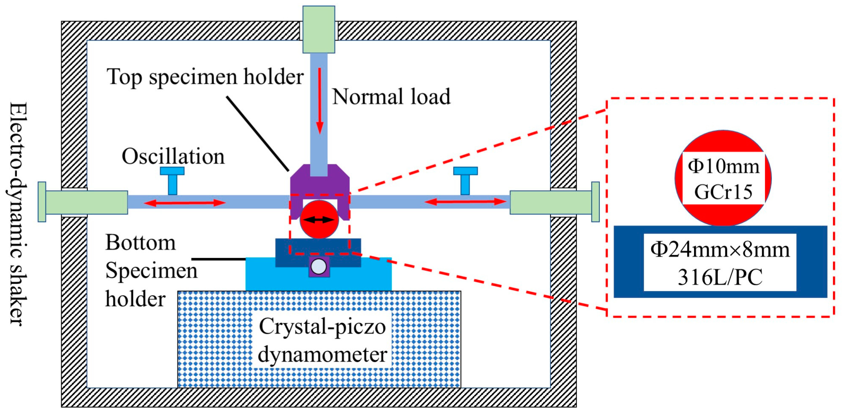
2.2. Fretting Friction and Wear Test

Fretting wear tests were performed with an SRV-V fretting friction and wear tester (SRV-V, Optimol Company, München, Germany), which automatically recorded the friction coefficient. The SRV-V is the model number of the machine. The schematic diagram of the fretting wear test is shown in Figure 1.
Fretting wear tests were performed in ball–plane point contact. The lower sample was a Φ24 mm × 8 mm 316L ASS cylinder. The upper sample was a Φ10 mm GCr15 ball. The main chemical composition of the GCr15 ball was as follows (wt.%): 1.60% Cr, 1.00% C, 0.30% Si, 0.30% Mn, 0.08% Mo, and 96.72% Fe. The surface hardness of the GCr15 ball was 62–65 HRC. The machining accuracy of GCr15 balls was G10. The above performance values were provided by the supplier. The upper and lower sample surfaces were cleaned before each test. The friction pair was abbreviated as GCr15/316L and GCr15/PC.
Each group of tests was repeated at least three times, and the analysis was performed using the most stable testing results. The test parameters are displayed in Table 3. In particular, it was noted that since all the tribological behaviors for this condition at an environmental temperature of 25 °C were detailed in reference [39], they would not be explored in this paper and only be quoted for comparative illustration.

2.3. Sample Characterization

Wear morphologies and elemental distributions were observed using field emission scanning electron microscopy (SEM, QUNTA FEG 450, FEI Company, Hillsboro, OR, USA) coupled with an EDS spectrometer. Surface roughness was measured using a laser confocal scanning microscope (LCSM, OLYMPUS OLS5000 3D, Olympus Corporation, Tokyo, Japan).

3. Results

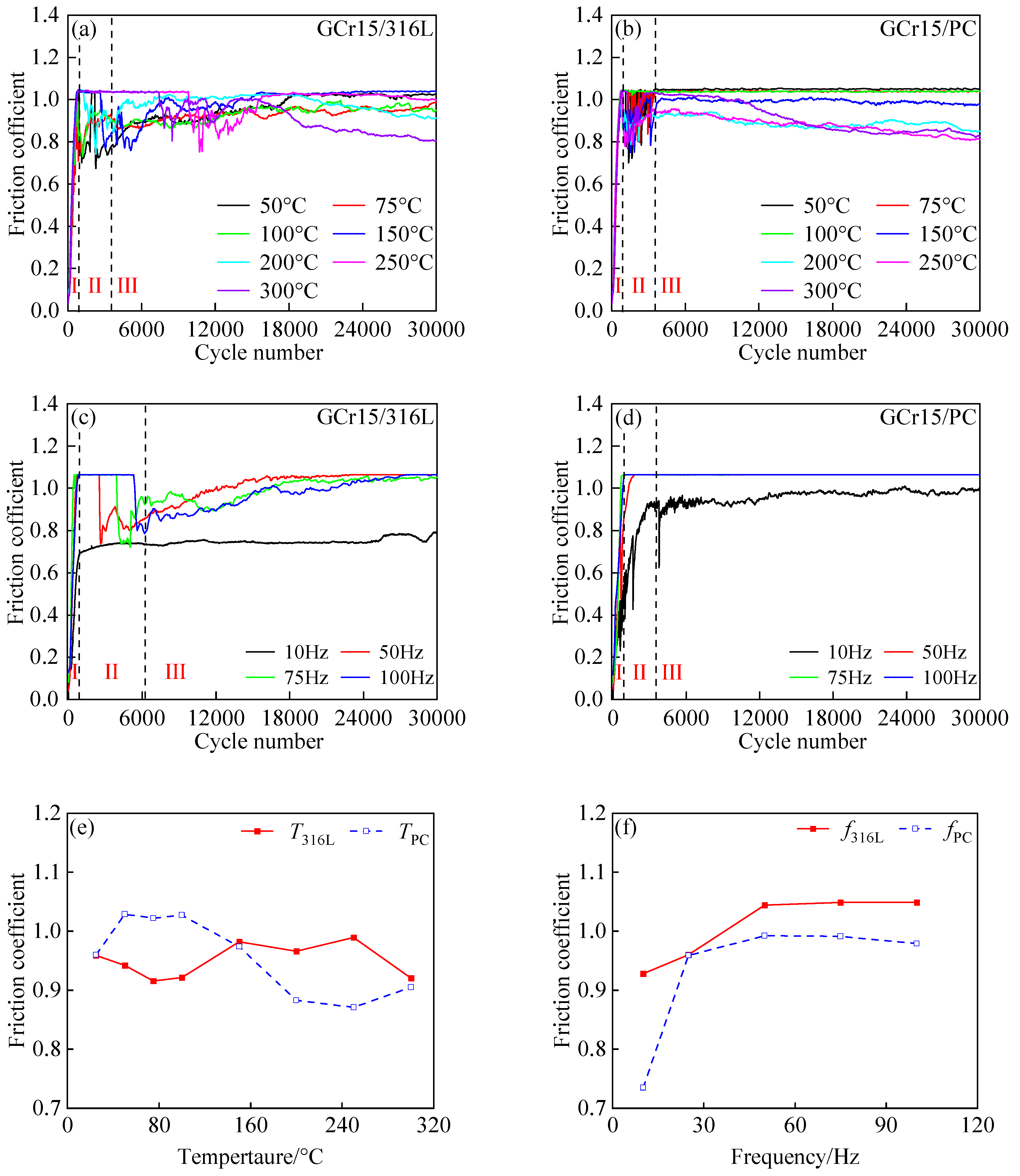
3.1. Friction Coefficient Analysis

The friction coefficient curves of 316L ASS and PC were obtained before and after plasma carburization under varying temperatures and frequencies, as shown in Figure 2. The curves showed three different stages [35,40,41]. (1) Running-in stage I: At the onset of fretting wear, when the upper and lower specimens made initial contact, the oxide films on their surfaces were crushed (including FeO, Fe2O3, Fe3O4, etc.) [5]. This exposed the “fresh surfaces” to direct contact, causing the friction coefficient to rapidly increase. The highest friction coefficient value was achieved in this stage. Upper–lower specimen contact occurred at micro-convex bodies, increasing the friction resistance and initiating debris generation. This explained the rapid increase in the coefficient of friction. (2) Fluctuation stage II: The friction coefficient decreased compared to the running-in stage. During this stage, although debris was generated and accumulated in large quantities, debris was also expelled due to upper sample reciprocating motion. This motion also caused large fragments of detached material to be ground into fine and hard particles. The accumulation and expulsion of debris had a competitive relationship, and the wear mechanism began to transition from two-body wear to three-body wear. The morphologic transformation and the movement of debris caused frequent oscillations in the friction coefficient, resulting in an unstable state. (3) Stable stage III: As temperature and frequency increased, a localized “frictional temperature rise” rapidly developed, leading to the accumulation of heat in the contact area. This caused the wear surface to develop an oxide film, and the debris particles accumulated and spread to form a debris layer (third-body layer). This debris layer separated the upper and lower specimens, preventing their direct contact. Thus, the wear process fully transitioned to three-body wear, and a stable wear state was maintained. The time required for GCr15/PC to enter the stable stage was lower than that for GCr15/316L.
Both materials initially showed an increase in the friction coefficient with increasing temperature followed by a decrease, as displayed in Figure 2a,b. When T < 200 °C, GCr15/PC showed a relatively stable friction coefficient. Increasing the temperature led to a higher frictional interface temperature, which caused material softening and intensified the adhesive effect at the contact interface. This made relative displacement between the friction pair surfaces more difficult, resulting in a higher friction coefficient. When T > 200 °C, the friction coefficient in the stable stage significantly decreased, which was possibly due to the generated oxide debris layer providing lubrication and a protective effect. Thus, the sliding properties of this layer improved the frictional state.
As frequency increased, GCr15/316L showed an increase in the friction coefficient, as indicated in Figure 2c,d. This was also true for GCr15/PC when f < 50 Hz. However, when f ≥ 50 Hz, GCr15/PC showed approximately coincident friction coefficients, with smooth, nearly linear friction coefficient curves and the disappearance of the fluctuation stage. At lower frequencies, the generation and expulsion of debris were competitive processes, causing the contact mode to alternate between two-body and three-body stages [9,10]. The number of hard oxide particles was small in the early wear stage and scattered in the contact area, which played a role in the abrasive grains, resulting in abrasive wear [5]. This resulted in an unstable wear process and fluctuating friction coefficient curves. However, as the frequency increased, the debris generated during the fretting wear process formed an oxide-containing layer through repeated friction, compression, and oxidation. This oxide debris layer filled into the wear interface to provide lubrication and protection for the carburized layer [31,42]. The combined effect of this oxide-containing debris layer and the hardening of the carburization layer created a well-matched state in the contact region. The two contacting surfaces rapidly reached an equilibrium point, resulting in smoother friction coefficient curves without dramatic fluctuations [8,20]. Plasma carburization had a smaller impact on the friction coefficient of 316L ASS when T > 200 °C and f ≥ 50 Hz. When T < 150 °C, μPC > μ316L, and when T ≥ 150 °C, μ316L > μPC (see Figure 2e). Both materials experienced an increase in the average friction coefficient with increasing frequency, and μ316L > μPC (see Figure 2f). The slightly higher friction coefficient of GCr15/PC compared to GCr15/316L might be attributed to factors such as the surface hardness, roughness, and crystal structure of the lower specimen as well as temperature rise and chemical interactions at the contact interface [39].
The changes to the friction coefficients of 316L ASS and PC caused by changing the temperature and frequency are illustrated in Figure 3 [30,43,44,45], where the arrows (↑) represent an increase in temperature or frequency, the plus signs (+) mean that the mechanism was facilitated positively, and the negative signs (-) mean that the mechanism was inhibited negatively. (1) Frictional temperature rise: increasing the frequency or temperature exacerbated the temperature rise at the contact interface, which promoted material softening, reduced hardness and shear strength, and caused severe plastic deformation. A sustained increase in interfacial temperature might lead to the recrystallization of the surface structure. On one hand, increasing the interfacial temperature facilitated the agglomeration and formation of a debris layer, which provided a “solid lubricant” effect that reduced the friction coefficient. On the other hand, a higher interfacial temperature also enhanced material adhesion effects, which increased the friction coefficient. (2) Tribo-chemical reaction time: increasing the frequency or decreasing the temperature could limit the duration of tribo-chemical reactions at the contact interface, which reduced the formation of the interfacial oxide film and consequently increased the friction coefficient. (3) Debris generation and ejection rates: higher frequencies or lower temperatures could accelerate the sliding velocity at the interface. Consequently, the rate at which debris was ejected from the contact interface increased, leading to a corresponding increase in the friction coefficient. Therefore, the friction coefficient was dominated by the tribo-chemical reaction time at low frequencies and by the friction temperature rise at high frequencies. The changes in the friction coefficient under different temperatures were caused by three factors. In the initial stages, the tribo-chemical reaction time was dominant, while in the middle and later stages, the frictional temperature rise became the primary influencing factor. These three factors collectively determined the morphological transformation and movement behavior of debris during the fretting wear process. They influenced the wear mechanism, wear morphology, and friction coefficients of 316L ASS before and after plasma carburization, ultimately determining the quality of the carburized layer.

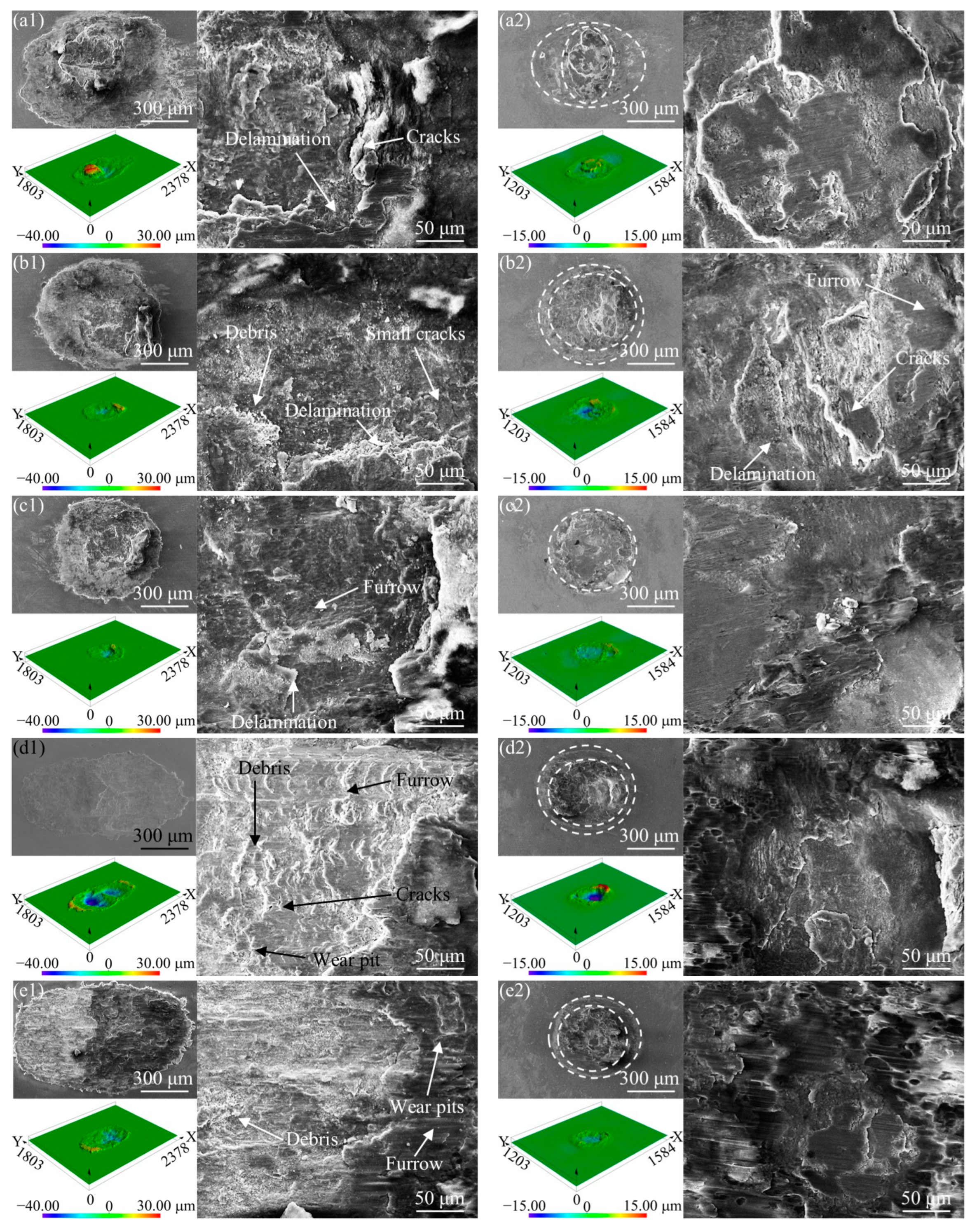
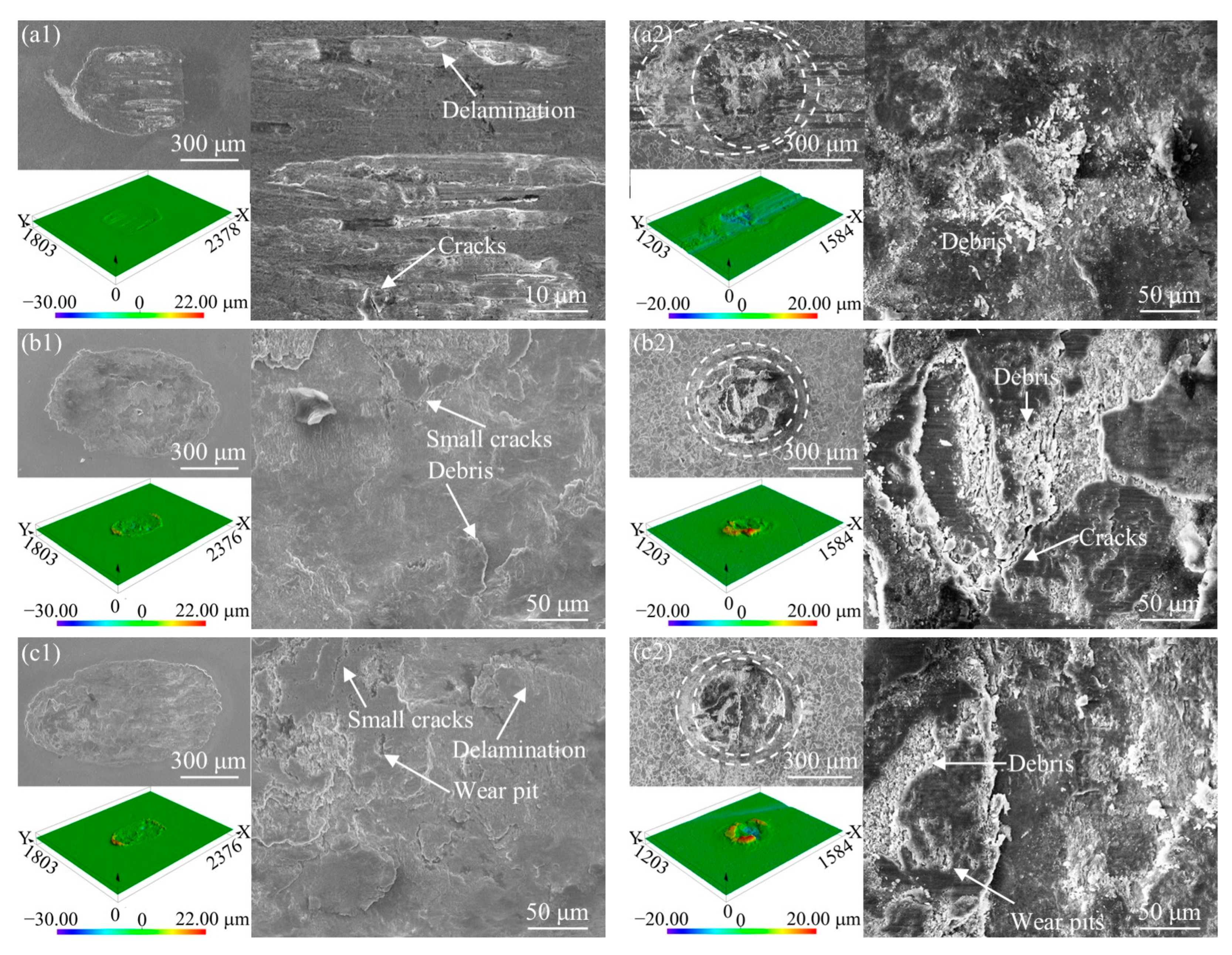
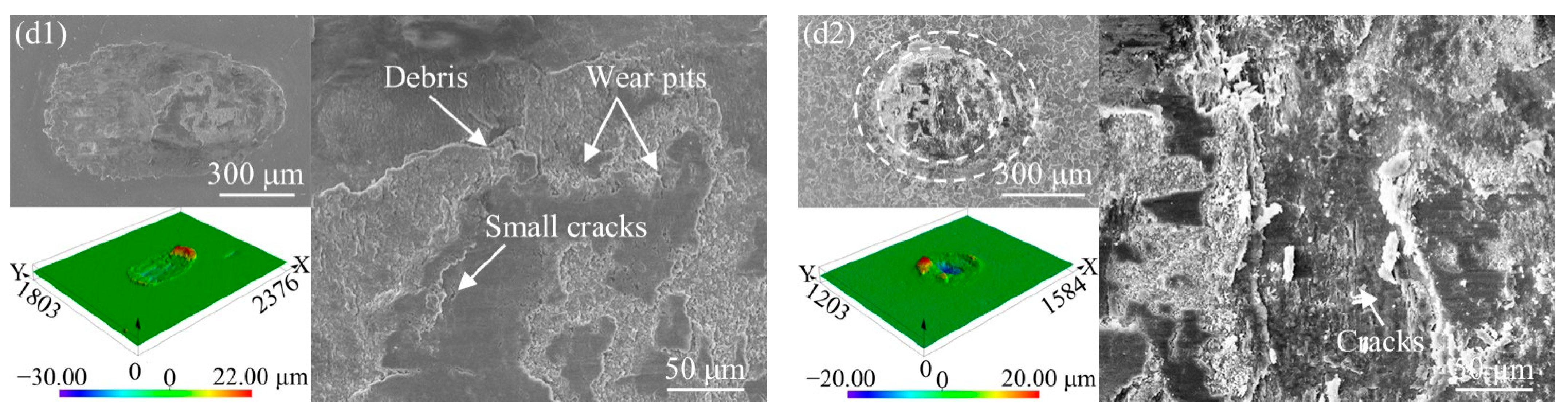
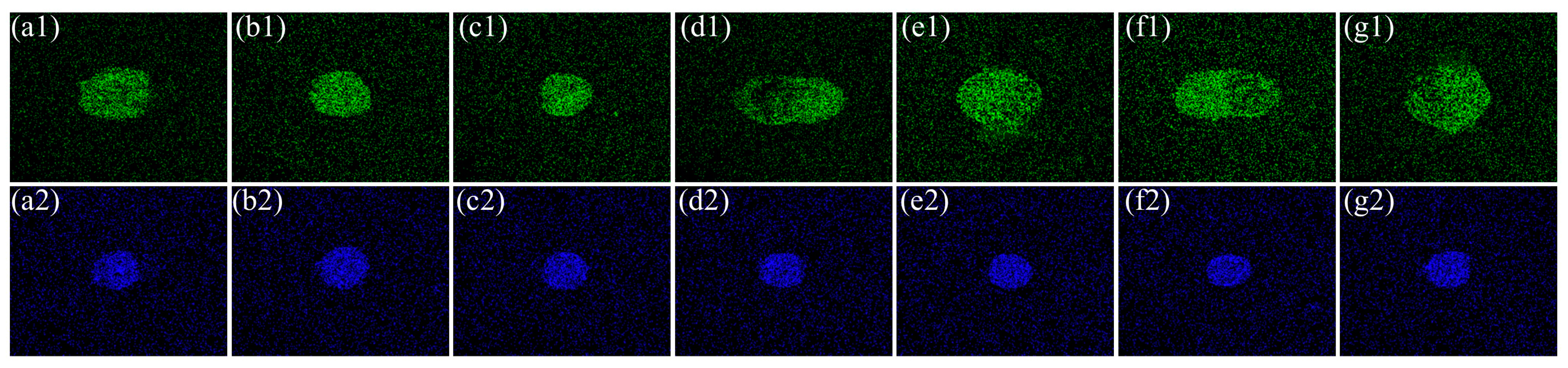
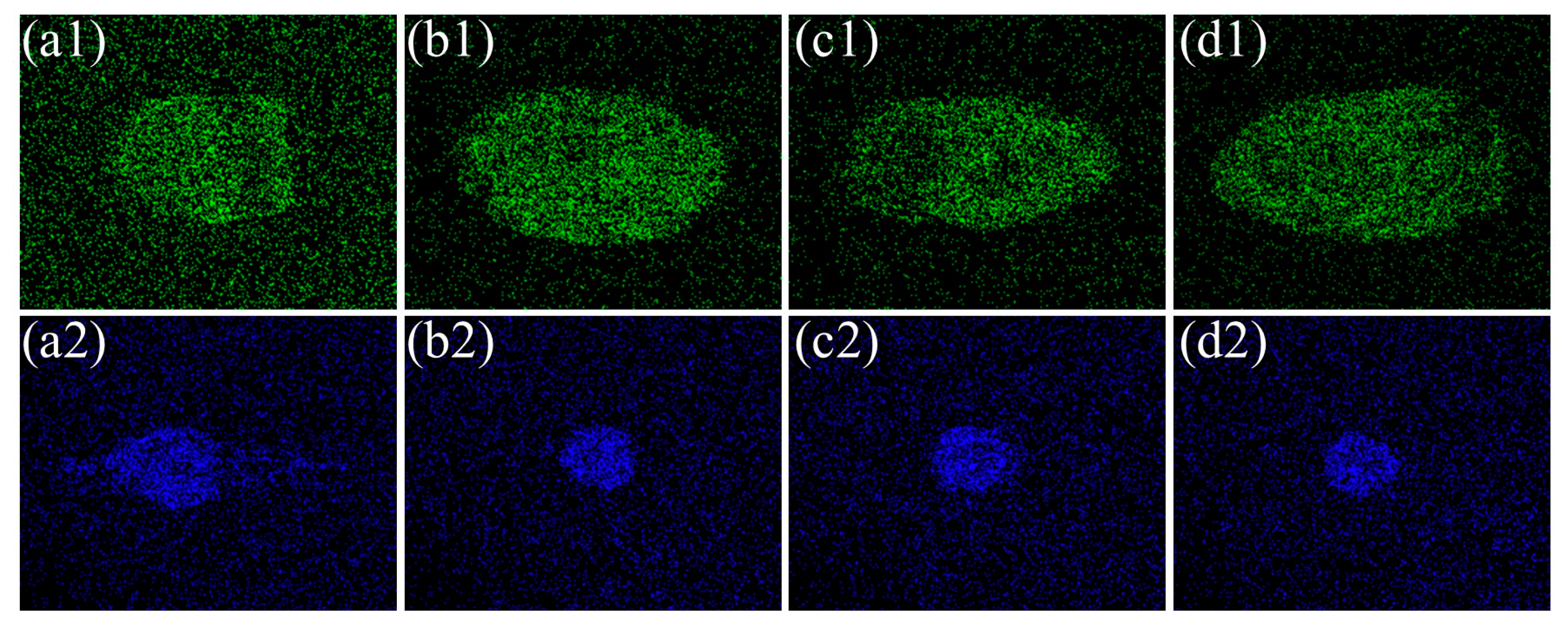
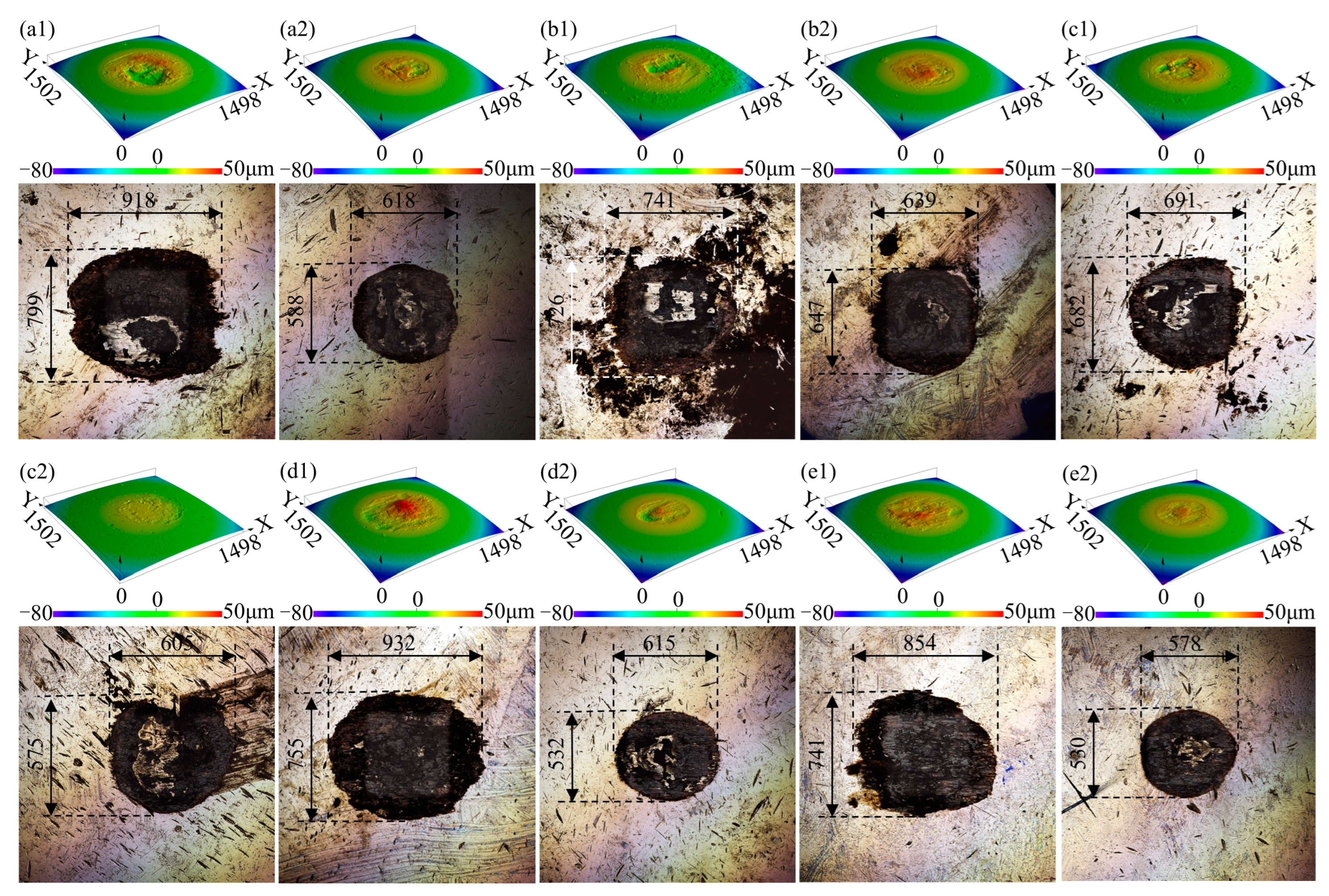
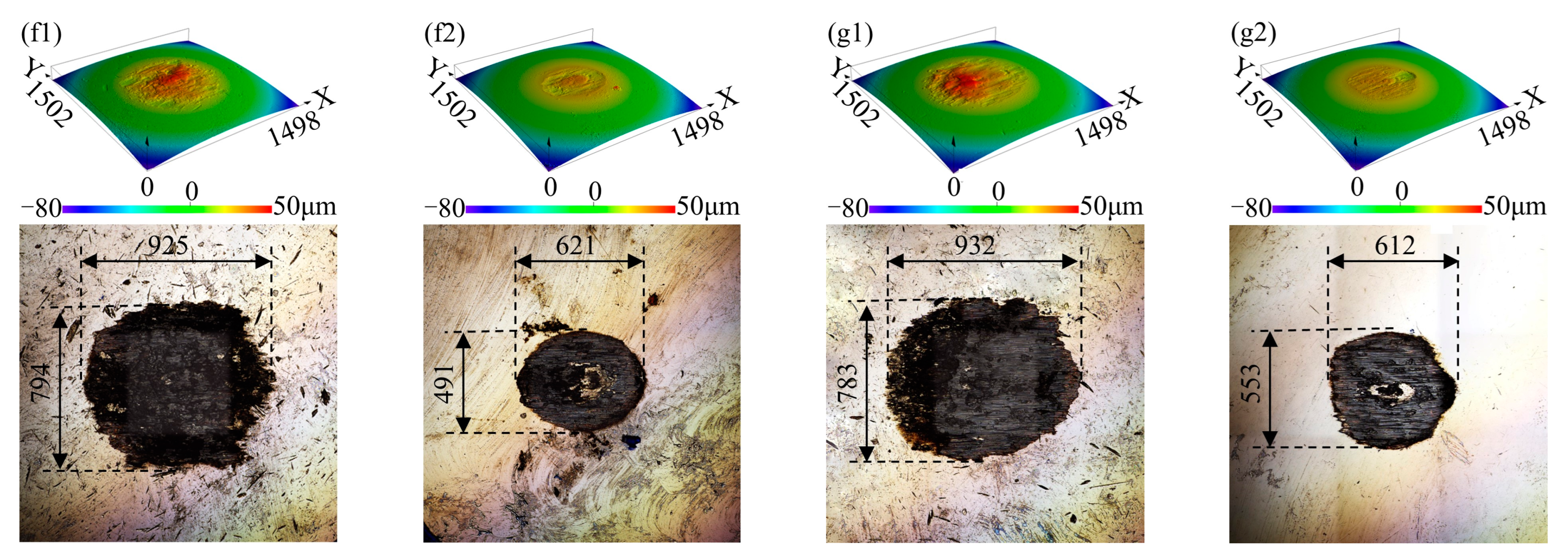
3.2. Wear Scar Morphology and Composition Analysis

The wear scar morphologies of 316L ASS and PC with varying temperatures are displayed in Figure 4. The wear scar morphology of 316L evolved from circular to elliptical as the temperature increased. The wear scars of PC predominantly exhibited a double-ring morphology. The central region of PC showed adhesive spalling and severe wear, while the edges display micro-sliding with minor scratches and abrasions, indicating less severe wear. The morphological changes in the 316L ASS wear scars were influenced by the high hardness of the carburized layer, the high degree of residual stress in this layer, and the presence of the Sc phase. The three-dimensional topography analysis revealed varying degrees of a plastic uplift at the edges of wear scars obtained under different temperatures on both the 316L ASS and PC samples. Due to the continuous close contact between the upper and lower specimens during fretting wear, debris accumulated at the edges and underwent repeated compression from the upper specimen because expulsion from the contact area was not easily achieved. Thus, cumulative plastic deformation occurred.
When T < 150 °C, localized areas of the 316L ASS wear scar exhibit a third-body layer formed by debris accumulation, as shown in Figure 4(a1,b1,c1). This layer was accompanied by material spalling, which formed debris layers. Small cracks induced by plastic deformation were distributed on the debris layer, and the further expansion of these cracks lead to material spalling and wear pits [46]. The peeled material was crushed by the upper specimen, forming fine debris particles. Adhesive wear occurred at the wear scar edges, where debris ejected from the central region accumulated, compressed, adhered, and agglomerated to form a stable, uniform debris layer. This stage exhibited a “GCr15 ball-debris layer” contact mode with low debris activity. The central area of the wear scar contained a scattering of fine debris particles. The micro-cutting effect of these debris particles gradually became significant, trending toward abrasive wear. The contact mode shifted to “GCr15 ball-debris particles/debris layer-316L,” which had higher debris activity.
When T ≥ 150 °C, the overall 316L ASS wear scar was smooth and even, as shown in Figure 4(d1,e1,f1,g1). A uniformly distributed debris layer without accumulation and fewer scattered debris particles could be observed. Small wear pits, furrows, and cataphracted peels were present on the debris layer. Some of the third-body layer debris beds gradually transformed into a “step-like” structure through accumulation and stacking, changing the contact mode from “GCr15 ball-316L” to “GCr15 ball-debris layer-316L”. As the temperature increased, parts of the third-body layer edges appeared to be bright white (see Figure 4(f1,d1)). This could be attributed to the repeated compression from the GCr15 ball causing severe plastic deformation and accumulation at the edges. “Glazed layers” appeared in localized areas of the wear scar (see Figure 4(e1,f1,g1)), indicating increasingly severe plastic deformation. This was because high temperatures induced the agglomeration, adherence, and accumulation of the free debris particles, causing the formation of “glazed layers” (plastic flow layers) under repeated compression from the upper specimen. Loose debris particles evolved into larger, more rigid abrasive particles, leading to localized stress concentration in these areas [32]. As the temperature increased, the 316L ASS wear mechanism transitioned from adhesive and abrasive wear to adhesive wear accompanied by plastic deformation and fatigue peeling.
The PC wear scar center also exhibits accumulated and spread debris layers, as shown in Figure 4(a2,b2,c2). The surface delamination, wear pits, and microcracks interspersed with fine debris particles indicated adhesive wear. As the temperature increased, material peeling on the debris layer surface became dense and apparent, indicating a transition from point- and pit-like spalling to layer-like spalling (see Figure 4(d2,e2,f2,g2)). The size and quantity of the spalled material increased, microcracks tended to grow, and adhesive wear became more severe with increasing temperature. Under the evaluated temperatures, PC exhibited an adhesive wear, plastic deformation, and fatigue peeling wear mechanism.
Under variable-frequency conditions, the 316L ASS wear scars were generally elliptical, while PC exhibited a double-ring morphology, as displayed in Figure 5. At lower frequencies, the center of the 316L ASS wear scar contained wear pits, delamination, and microcracks. Meanwhile, the PC wear scar center showed scattered debris particles of varying sizes, and debris layers formed through adhesion and compression, with slight surface peeling (see Figure 5(a1,a2)). The PC sample showed an abrasive and adhesive wear mechanism. As the frequency increased, large areas of material peeling appeared in the 316L ASS wear scar, with slight glazing characterized on the debris layer surface (see Figure 5(b1,c1,d1)). 316L ASS displayed an adhesive wear and fatigue peeling wear mechanism. The PC wear scar center exhibited “step-like” and “block-like” debris layers, with numerous scattered debris particles and intersecting microcracks interspersed with wear pits and scratches (see Figure 5(b2,c2,d2)). Fatigue peeling characteristics were evident, and the contact mode changed from “GCr15 ball-PC layer” to “GCr15 ball-debris particles/debris layer-PC layer”. The wear mechanisms of PC included fatigue peeling as well as abrasive and adhesive wear. As the debris layer thickens through accumulation, the combined effect of contact pressure and shear force caused the third-body layer to tear, producing microcracks that further expand and converge [32,46]. This resulted in fatigue peeling.
During fretting wear, the lower specimen experienced contact pressure and shear force, causing cumulative fatigue damage that led to stress concentration at internal defects [9,10]. This induces the generation, expansion, and connection of microcracks. When a crack length reached and exceeded a critical length, local instability occurred in the carburized layer, causing partial or complete detachment. Therefore, debris was formed, and this debris was further refined under repeated compression from the friction pair. This debris participated in wear as a third body, with the GCr15 ball driving debris particles to create scratches and plowing (cutting) effects, resulting in parallel, uniform scratches on the debris layer surface in the direction of motion [8,41]. As the frequency increased, 316L ASS showed a fatigue peeling and adhesive wear mechanism, while that of PC transitioned from abrasive and adhesive wear to fatigue peeling, abrasive wear, and adhesive wear.
The oxygen distributions in the 316L ASS and PC wear scars generated at different frequencies and temperatures are exhibited in Figure 6 and Figure 7. Both the 316L ASS and PC wear scars showed significant oxygen accumulation under the different frequency and temperature conditions, indicating the presence of oxidative wear and accumulation of oxide wear debris during fretting wear.
Under low-frequency and low-temperature conditions (T = 150 °C, f = 10 Hz), the wear scars of 316L ASS showed significantly lower oxygen content than the PC wear scars, as shown in Table 4 and Table 5. It was assumed that at T = 150 °C and f = 10 Hz, the 316L ASS wear mechanism began to transition, with adhesive wear becoming more severe, leading to change in the oxygen content. Combined with Figure 4 and Figure 5, it could be seen that the adhesive wear increased. However, under all other conditions, both samples showed similar oxygen levels. As f = 25 Hz and 50 Hz, the oxygen content of 316L ASS is higher than that of the carburized layer. The oxidative wear and adhesion effect of 316L ASS were more severe, and with the frequency further increased, the oxygen content of the samples was similar, and compared with the oxygen content of the low-frequency condition, it was reduced. This indicated that the carburized layer could play out its advantage of reducing the adhesion effect at high frequency. The degree of oxidative wear of the specimens in the variable-temperature condition was more severe than that in the variable-frequency condition.
The wear scar morphologies of GCr15 balls generated at different temperatures and frequencies are displayed in Figure 8 and Figure 9. The GCr15 balls from the GCr15/PC pairs showed consistently smaller wear scar surface areas than the balls from the GCr15/316L pairs. The GCr15 balls paired with PC exhibited less severe wear, indicating that LTPC could mitigate GCr15 ball wear. As the temperature and frequency increased, debris accumulation in the central region of the GCr15 balls increased, with adhesion becoming progressively severe in the center. These GCr15 balls showed two main wear scar morphologies: (1) concave pits formed by depressions in the center due to material peeling, with debris accumulation and a plastic uplift at the edges; (2) double-ring morphology consisting of circular protrusions formed in the wear scar centers due to debris accumulation, concave pits caused by material peeling at the edges, and a slight plastic uplift and debris accumulation at the outermost edges. The GCr15 balls exhibited more severe central wear compared to edge wear, which was possibly due to the ball–plane fretting wear process. In this process, the center of contact bore greater pressure when the lower specimen was compressed by the applied load. This meant that damage initiated at the contact center and spread toward the edges. Additionally, debris generated during the wear process continuously accumulated as a third body, participating in the fretting wear process. This resulted in the contact surface experiencing uneven load distribution. The GCr15 ball drove debris from the center toward the edges, indirectly causing more severe wear in the central region.

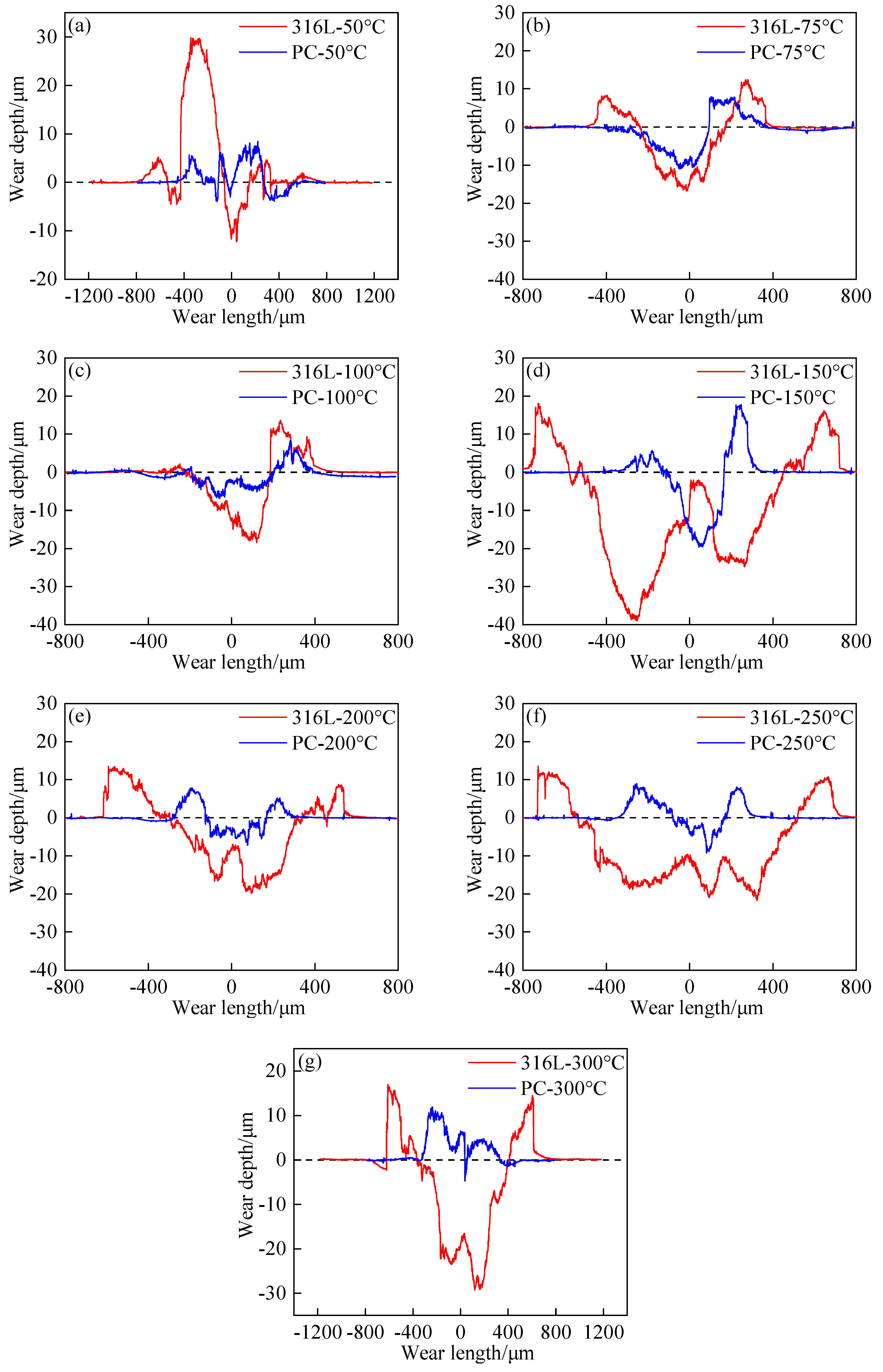
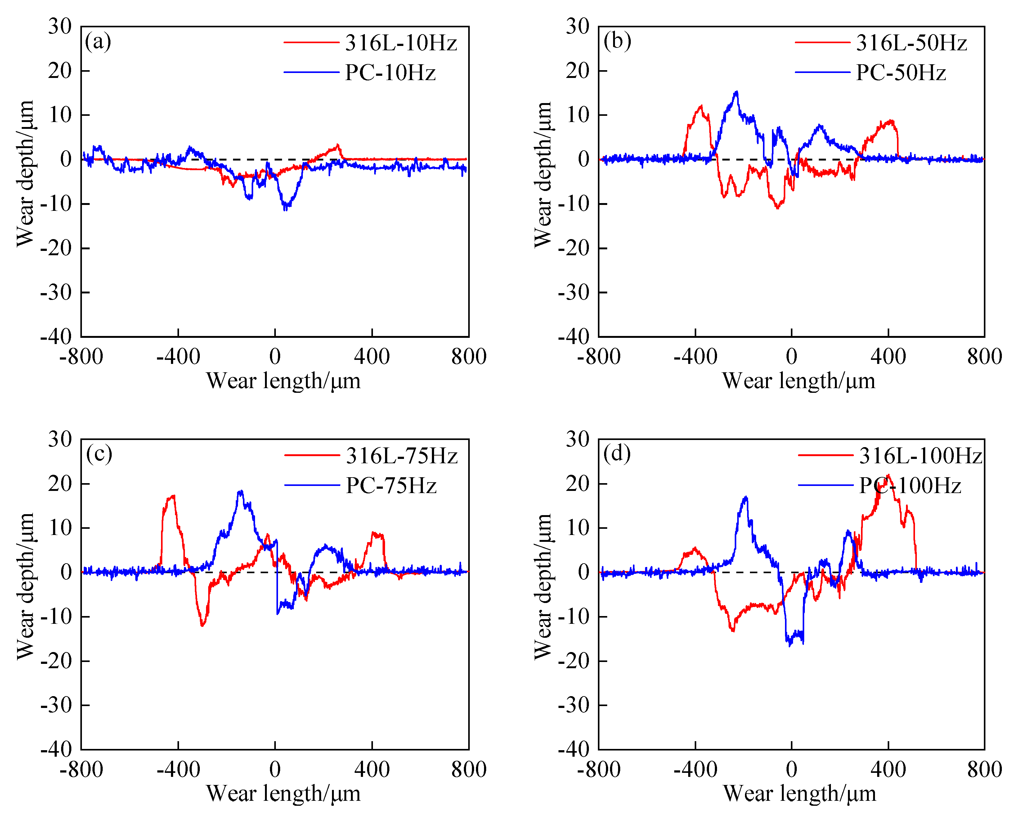
3.3. Wear Profile Analysis

The wear profiles of 316L ASS and PC at various temperatures and frequencies along the X-axis (in the direction of motion) are illustrated in Figure 10 and Figure 11. These wear profile curves are not smooth and even. This is because the friction pair surfaces contained numerous micro-convex bodies and were not ideal planes.
During the fretting wear process, contact and wear are first initiated between higher micro-convex bodies, while lower micro-convex bodies remain protected without contact, resulting in uneven wear and fluctuations in the wear profile [47]. Across different frequencies and temperatures, GCr15/316L showed higher wear depths than GCr15/PC. At T = 150 °C, the maximum wear depth of PC was 20 μm, while at f = 100 Hz, PC exhibited a maximum wear depth of 18 μm (see Figure 10d and Figure 11d). Given that the carburized layer thickness was 25 μm, this indicated that PC was not worn through under the selected frequency and temperature conditions, demonstrating that plasma carburization could effectively protect 316L ASS. Combined with the three-dimensional topography of the wear scars, it was evident that both the 316L ASS and PC wear profiles had portions above the reference plane, indicating debris accumulation and a plastic uplift caused by repeated extrusion. This was particularly pronounced at high frequencies, where the peaks formed by a plastic uplift were significantly higher than the troughs caused by wear, suggesting severe adhesive wear and plastic deformation in both 316L ASS and PC under the varying frequency and temperature conditions. The carburized layer showed less plastic uplift. This could be explained by the grain refining effect of plasma carburization, which resulted in more grain boundaries and enhanced the plastic deformation capacity of 316L ASS [35].
GCr15/316L initially showed an M-type wear profile. As the temperature increased, this shifted to a V-type and then W-type profile. Meanwhile, that of GCr15/PC transitioned from W-type to V-type to M-type. With increasing frequency, GCr15/316L showed a wear profile transition from arc-type to W-type, while that of GCr15/PC evolved from V-type to M-type.
When adhesive wear was bidirectional and the wear depth was notably larger than the wear width, a “V” shape formed and damage tended to develop in the depth direction. In this case, the upper and lower specimens had point contact. A “W” shape formed when the adhesive wear at the edges was less severe than that in the center of the wear scar, and spalling and tearing occurred at the edges first. Under frictional heat and the reciprocating motion of the upper specimen, the severe debris accumulation at the edges could transform the “W” profile into an “M” profile [30]. An “arc” shape formed when debris generated within the wear scar during the wear process was promptly expelled. Damage entirely developed in the depth direction, and debris did not accumulate to form a plastic uplift. The appearance of these profile types indicated that adhesive and oxidative wear primarily contributed to the overall fretting wear mechanism. This analysis corresponded to the wear scar morphologies observed in Figure 4 and Figure 5.

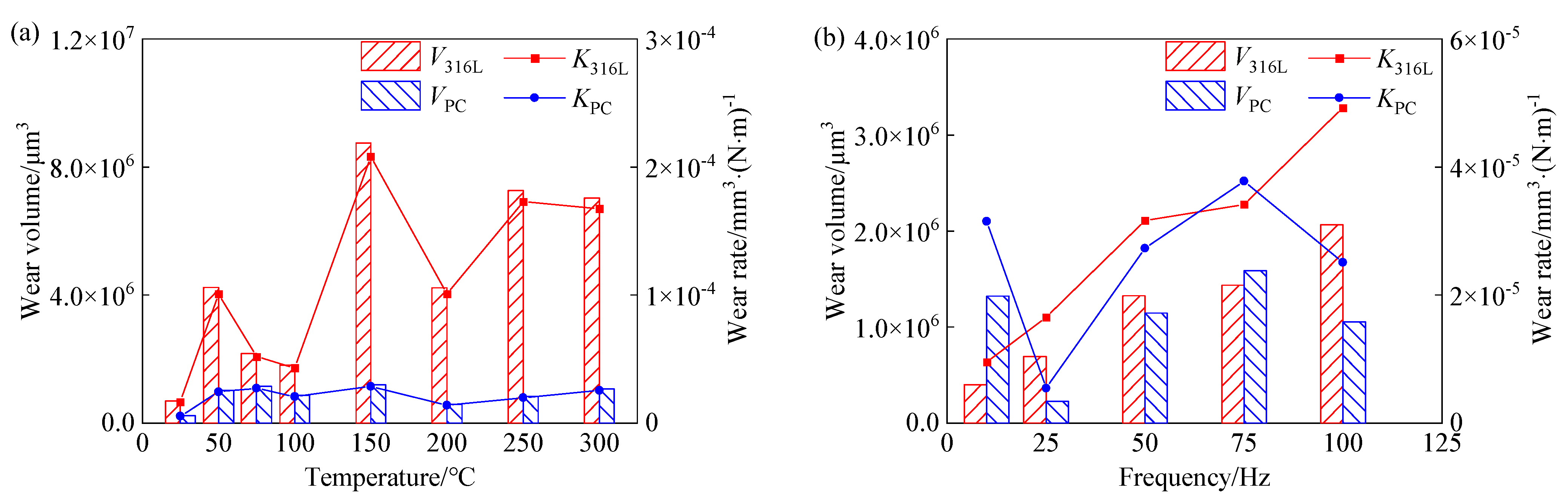
3.4. Wear Volume and Wear Rate Analysis
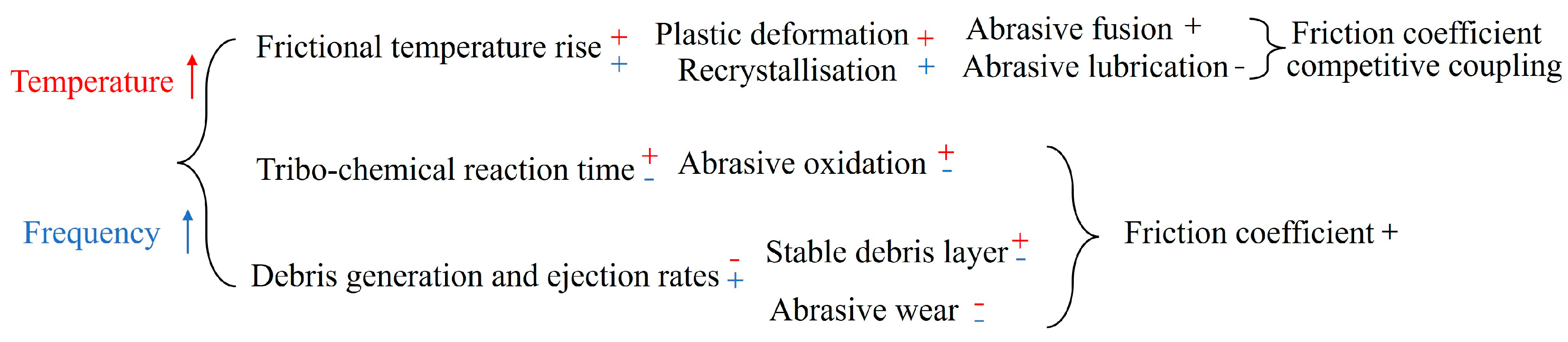
The wear resistance of the samples was evaluated using the wear volumes and rates obtained under different temperatures and frequencies. The wear rate (K) is calculated using the following formula [48]:
K = V 4 N D F
where K is the wear rate (mm3·(N·m)−1), V is the wear volume (mm3), N is the cycle number, D is the displacement amplitude (m), and F is the normal load (N).
The wear volumes and wear rates of 316L ASS and PC at different temperatures and frequencies are displayed in Figure 12. At different temperatures, GCr15/PC showed a consistently lower wear volume and wear rate than GCr15/316L. The wear volume of GCr15/PC increased approximately linearly with temperature. However, when T < 150 °C, GCr15/316L showed an initial increase in the wear volume and rate with increasing temperature, followed by a decrease. When T ≥ 150 °C, GCr15/316L showed an increase, decrease, and then increase in the wear volume and wear rate with increasing temperature. Meanwhile, as frequency increased, GCr15/PC showed a decrease, increase, and then decrease in the wear rate and volume. GCr15/PC generally had lower wear rates and volumes than GCr15/316L.
Combining the observations from Figure 2c,d and Figure 4 demonstrated that at T = 150 °C, the 316L ASS wear mechanism began to transition, with adhesive wear becoming more severe and the initiation of glazing phenomena. This led to a sharp increase in the wear volume and wear rate. High temperatures significantly affected the morphology and movement of debris. The rise in temperature and reciprocating motion of the GCr15 ball increased the activation energy of loose, fine debris particles, promoting their agglomeration and adhesion to form a “glazed layer”. This layer provided a lubricating effect, leading to a reduction in the wear volume and wear rate as well as the mitigation of fretting damage [27,28,41]. However, because numerous rough “micro-convex bodies” were often encapsulated in this glazed layer, the accumulation of the glazed layer to a certain thickness could cause fluctuations in the friction coefficient and exacerbate fretting damage. Consequently, the wear volume and wear rate increased. Due to its lower hardness, 316L ASS was more sensitive to temperature effects and was prone to intensified adhesion during fretting wear, which affected the wear volume and wear rate. The high hardness, high residual stress, and high strength of PC mitigated adhesion and plastic deformation, the impact of raising the temperature on debris evolution. The combined effect of accumulated oxide debris layers at the interface and surface hardening layers enhanced the wear resistance of 316L ASS [41,49]. Thus, under the variable-temperature conditions, the wear scar morphology and wear rate of 316L ASS were more significantly impacted than those of PC by the morphology and movement behavior of debris.
At low frequencies, the debris formed during fretting wear was not easily ejected from the contact area. Instead, this debris was scattered within the contact region and formed “rolling balls” to increase wear. Thus, the debris acted as a third body and participates in the wear process. Due to the higher hardness of PC, the hard-phase debris particles produced by GCr15/PC were less likely to agglomerate and adhere at low frequencies, exacerbating abrasive wear. Consequently, GCr15/PC experienced a higher wear volume and wear rate compared to GCr15/316L at f = 10 Hz. However, at higher frequencies, the resulting increase in the interface temperature led to the solidification of debris particles. The agglomeration of debris particles caused the formation of more rigid and abrasive single particles, which enhanced the abrasive characteristics of the debris and weakened its adhesive effects. When the GCr15 ball contacted these abrasive particles during fretting, severe abrasive wear instantaneously occurred. This increased the local damage and stress concentration, producing high stress. At this point, the operation of the equipment might lead to the generation of high noise and vibration, and sample clamping or pressure head loosening might occur. This could lead to unstable fretting wear processes. Consequently, at f = 75 Hz, GCr15/PC showed a higher wear volume and wear rate compared to GCr15/316L. Therefore, under the harsher conditions provided by elevated temperatures and frequencies, greater attention should be paid to thermal fatigue effects and vibration noise pollution between friction pairs to prevent fretting instability and the premature failure of the film layer [8,32]. Further analyses are still needed for abnormal points (f = 10 Hz, 75 Hz) occurring in different frequency conditions.

4. Discussion

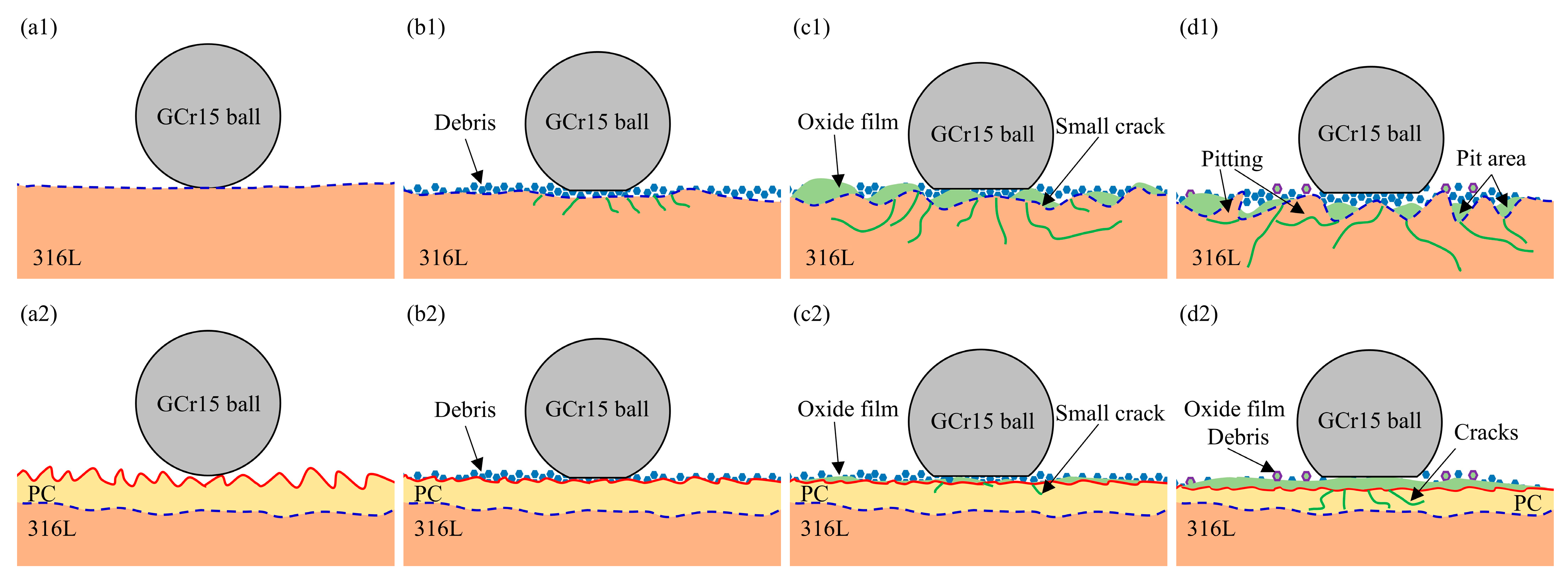
4.1. Fretting Wear Analysis

The fretting wear mechanisms of 316L ASS and PC under different temperatures and frequencies can be described using four stages (see Figure 13). (1) Initial friction stage: At the onset of fretting wear, the GCr15 ball applied a normal load, which compressed the lower sample, and small reciprocating motions were initiated. This formed the initial wear morphology. At this stage, only minimal interface fretting wear developed, but the maximum contact stress was instantly achieved. This stage involved two-body “GCr15 ball-316L (PC)” contact with a sphere–plane to the asperity contact mode. (2) Debris formation stage (transition from two-body to three-body contact): As fretting wear progressed, the interfacial material was continuously damaged, spalled, and refined into debris under shear and compressive forces. This stage involved two-body and three-body “GCr15 ball-316L (PC)” mixed contact with an arc surface–plane contact mode. The number of hard oxide particles was small and scattered in the contact area, which played a role in the abrasive grains, resulting in the abrasive wear. In this stage, more severe wear morphologies such as wear pits, cracks, slight adhesion, and scratches were formed. (3) Three-body contact stage: Debris continued to accumulate at the contact interface. Increasing the temperature and frequency lead to a rise in temperature at the contact interface, causing debris to accumulate and adhere into form debris layers. The substrate material softened, which reduced the hardness and shear strength while increasing plasticity. This resulted in adhesive wear. The remaining scattered debris promotes abrasive wear, further intensifying the fretting wear. The wear pit depth increased, leading to the formation of severe adhesion, fatigue peeling, furrow, abrasive wear, and plastic flow damage morphologies. The contact mode became “GCr15 ball-debris layer-316L (PC)” three-body contact with plane-to-plane contact. (4) Oxide film formation and action stage: This stage might occur during stages 2 and 3. In the later stages of fretting wear, the combined effects of the ambient temperature, frequency, and increase in frictional temperature at the contact interface caused the generation of oxide particles on the debris layer surface. These oxide particles accumulated and participated in the wear process, forming a bed of oxide abrasive debris in the wear interface (the third-body layer), which could provide a lubricating and friction-reducing effect [50,51]. At this stage, adhesive, abrasive, and oxidative wear mainly contributed to the wear mechanism. Metal oxides had both effects of intensifying and slowing down the fretting wear, which depended on the state of metal oxides (size, shape, viscosity). Oxidative wear was a process in which both chemical oxidation and mechanical wear occurred in fretting wear [5].
Fretting wear was typically accompanied by mechanical, heat transfer, and chemical reaction processes, which could cause plastic deformation, material transfer, or microstructural changes at the contact interface. Physical processes related to temperature and friction frequency variations competed with each other. The specific fretting wear mechanism depended on which influencing factor dominated as well as the changes in substrate material composition and structure [20,28].

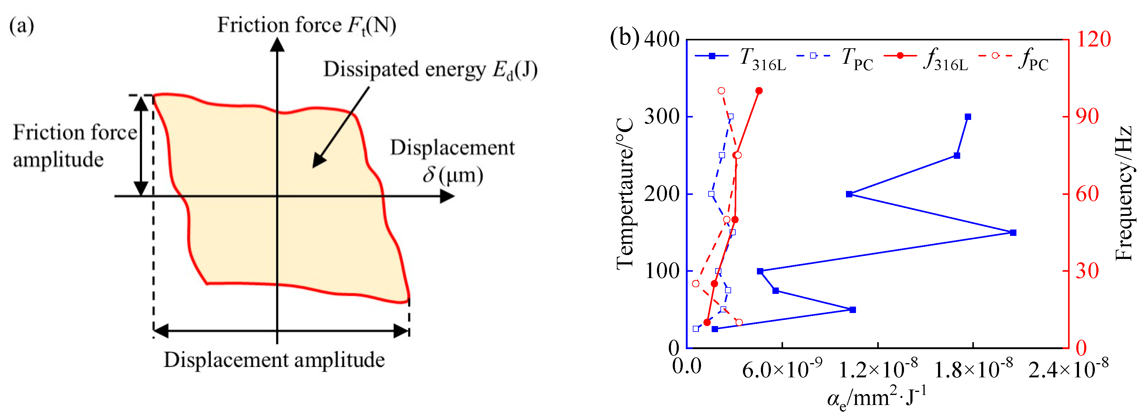
4.2. Frictional Dissipation Energy Analysis

A schematic diagram of the frictional dissipated energy is displayed in Figure 14a. Frictional dissipation energy (Ed), which is the integral of the area enclosed by the hysteresis curve, could be employed to assess fretting wear stability and characterize the evolution trend of material damage. The frictional dissipation energy (Ed) and frictional dissipation energy coefficient (αe) are calculated using the following formula [52]:
E d = i = 1 i = N 4 μ F i D i
α e = V E d
where Ed is the frictional dissipation energy (J), μ is the friction coefficient, D is the displacement amplitude (m), F is the normal load (N), i is the cycle number, αe is the frictional dissipation energy coefficient (mm2·J−1), and V is the wear volume (mm3).
Under varying frequency and temperature conditions, GCr15/316L showed frictional dissipation energy coefficients that were generally higher than those of GCr15/PC, as shown in Figure 14b. This indicated that PC had a more stable fretting wear process, demonstrating that plasma carburization could enhance the fretting wear stability of 316L ASS.
For GCr15/PC, as frequency increases, the high hardness of PC accelerated the refinement and expulsion of interfacial debris during the fretting wear process. This meant that the transition from two-body wear to three-body wear happened more rapidly. A dynamic equilibrium was quickly reached between the expulsion and generation of debris, resulting in a smoother contact interface with fewer micro-convex bodies. The GCr15/PC contact interface mainly experienced material loss via shear. This interface entered the plastic stability stage, and the wear interface tended to be stable. Increasing the frequency led to a higher rise in interfacial temperature, which promoted the rapid growth of the interfacial oxide film. This provided a lubricating effect. The combined action of the oxide film and hardened surface layer meant that GCr15/PC had a lower frictional dissipation energy coefficient than GCr15/316L.
As the environmental temperature rose, sustained high “frictional flash temperatures” were generated at multiple local points on the contact interface, providing the PC with a sufficient reaction activation energy and a higher reaction rate. Under the dual effects of friction and temperature, the contact surface of PC experienced a frictional glazing effect, which involved the exchange of material and energy to form a protective glazed film. This weakened the wear damage [53,54,55]. Due to the higher rise in interfacial temperature, the agglomerated debris particles formed abrasive particles, causing local stress concentration. The resulting high stress led to microstructural changes in PC during wear, resulting in work hardening at the wear interface. Residual stress concentration on the wear surface caused the PC contact interface to undergo an increase in local hardness and mechanical strength. The high hardness and mechanical strength of the contact surface caused by frictional glazing and work hardening mean that GCr15/PC had a lower friction dissipation energy coefficient.

5. Conclusions

The fretting wear behavior of 316L ASS under different temperatures and frequencies was investigated before and after LTPC. Fretting wear features were characterized using SRV-V, SEM, and LCSM to analyze the fretting wear behavior and mechanism of 316L ASS and the carburized layer. The following conclusions were made:
(1) The friction coefficient curves could be divided into running-in, wear, and stable stages. As frequency increased, the average friction coefficients of both 316L and PC increased, with μ316L > μPC. When T < 150 °C, μPC > μ316L; when T ≥ 150 °C, μ316L > μPC. When T > 200 °C and f ≥ 50 Hz, plasma carburization had a weaker effect on the friction coefficient of 316L ASS.
(2) As temperature increased, the wear mechanism of 316L ASS transitioned to adhesive wear accompanied by plastic deformation, fatigue peeling, and oxidative wear, while the wear mechanism of PC involved adhesive wear, plastic deformation, fatigue peeling, and oxidative wear. As frequency increased, adhesive wear, oxidative wear, and fatigue peeling contributed to the 316L ASS wear mechanism, while the PC wear mechanism transitioned from abrasive and adhesive wear to abrasive wear, adhesive wear, and fatigue peeling coupled with oxidative wear.
(3) Under varying temperature and frequency conditions, GCr15/PC showed wear depths that were consistently lower than those of GCr15/316L, indicating that plasma carburization could protect 316L ASS. As the temperature increased, the initial M-type wear profile of GCr15/316L transitioned to V-type and then W-type, while that of GCr15/PC shifted from W-type to V-type to M-type. As the frequency increased, the GCr15/316L wear profile evolved from arc-type to W-type, while that of GCr15/PC changed from V-type to M-type.
(4) Under different temperatures and frequencies, GCr15/316L showed wear rates and frictional dissipation energy coefficients that were generally higher than those of GCr15/PC. Good fretting wear resistance was provided by the carburized layer, indicating that the wear stability of 316L ASS was improved by plasma carburization. This provided protection for both the upper and lower samples.
(5) The rise in frictional temperature, the tribo-chemical reaction time, and the evolution of debris collectively influenced the wear mechanisms and wear morphologies of 316L ASS before and after plasma carburization.

Author Contributions

L.S. prepared the samples, performed the experiments, and wrote the manuscript. Y.L. edited and reviewed the manuscript. C.C. prepared the carburized samples. G.B., J.Q. and X.L. contributed to the technical discussions of the results. All authors have read and agreed to the published version of the manuscript.

Funding

This research was funded by the Key Science and Technology Project of Gansu Province, China (No. 20YF8GA058); Science and Technology Project of Wenzhou City, China (No. ZG20211003); and Major Science and Technology Project of Gansu Province, China (No. 22ZD6GA008).

Institutional Review Board Statement

Not applicable.

Informed Consent Statement

Not applicable.

Data Availability Statement

Data are contained within the article.

Conflicts of Interest

The authors declare no conflicts of interest.

References

  1. Baydoun, S.; Fouvry, S.; Descartes, S.; Arnaud, P. Fretting Wear Rate Evolution of a Flat-on-flat Low Alloyed Steel Contact: A Weighted Friction Energy Formulation. Wear 2019, 426–427, 676–693. [Google Scholar] [CrossRef]
  2. Wang, S.; Khatir, S.; Wahab, M.A. Proper Orthogonal Decomposition for the Prediction of Fretting Wear Characteristics. Tribol. Int. 2020, 152, 106545. [Google Scholar] [CrossRef]
  3. Ma, X.; Tan, W.; Bonzom, R.; MI, X.; Zhu, G.R. Impact-sliding Fretting Tribocorrosion Behavior of 316L Stainless Steel in Solution with Different Halide Concentrations. Friction 2023, 11, 2310–2328. [Google Scholar] [CrossRef]
  4. Wang, J.; Chen, T.; Zhou, C. Crystal Plasticity Modeling of Fretting Fatigue Behavior of an Aluminum Alloy. Tribol. Int. Tribol. Int. 2021, 156, 106841. [Google Scholar] [CrossRef]
  5. Wen, S.Z. Principles of Tribology; Tsinghua University Press: Beijing, China, 1990. [Google Scholar]
  6. Wang, M.J.; Wang, Y.X.; Wang, J.Z.; Fan, N.; Yan, F.Y. Effect of Heat Treatment Temperature and Lubricating Conditions on the Fretting Wear Behavior of SAF 2507 Super Duplex Stainless Steel. J. Tribol. 2019, 141, 10160. [Google Scholar] [CrossRef]
  7. Chen, Q.; Xu, X.; Li, A.; Zhang, Q.; Yang, H.; Qiu, N.; Wang, Y. Fretting Wear Resistance of Amorphous/Amorphous (AlCrFeNi)N/TiN High Entropy Nitride Nanolaminates. J. Mater. Sci. Technol. 2023, 182, 41–53. [Google Scholar] [CrossRef]
  8. Shi, Z.K.; Xu, L.P.; Deng, C.M.; Liu, M.; Liao, H.L.; Geoffrey, D.; Pierre, M.P. Effects of Frequency on the Fretting Wear Behavior of Aluminum Bronze Coatings. Surf. Coat. Technol. 2023, 457, 129306. [Google Scholar] [CrossRef]
  9. Zhu, M.; Cai, Z.; Zhou, Z. Fretting Wear Theory; Science Press: Beijing, China, 2021. [Google Scholar]
  10. Zhu, M.; Cai, Z.; Zhou, Z. Fretting Wear Under Special Condition; Science Press: Beijing, China, 2022. [Google Scholar]
  11. Jiang, L.; Luo, H.; Zhao, C. Nitrocarburising of AISI 316 Stainless Steel at Low Temperature. Surf. Eng. 2018, 34, 205–210. [Google Scholar] [CrossRef]
  12. Montanari, R.; Lanzutti, A.; Richetta, M.; Tursunbaev, J.; Vaglio, E.; Varone, A.; Verona, C. Plasma Carburizing of Laser Powder Bed Fusion Manufactured 316L Steel for Enhancing the Surface Hardness. Coatings 2022, 12, 258. [Google Scholar] [CrossRef]
  13. Zulić, S.; Rostohar, D.; Kaufman, J.; Pathak, S.; Kopeček, J.; Böhm, M.; Brajer, J.; Mocek, T. Fatigue Life Enhancement of Additive Manufactured 316l Stainless Steel by LSP Using a DPSS Laser System. Surf. Eng. 2022, 38, 183–190. [Google Scholar] [CrossRef]
  14. Dalibón, L.E.; Moreira, D.R.; Heim, D.; Forsich, C.; Brühl, P.S. Soft and Thick DLC Deposited on AISI 316L Stainless Steel with Nitriding as Pre-Treatment Tested in Severe Wear Conditions. Diam. Relat. Mater. 2020, 106, 107881. [Google Scholar] [CrossRef]
  15. Lv, J.L.; Zhou, Z.P.; Jin, H.J. The Effects of Cold Rolling and Building Orientation on Sensitization of Laser Powder Bed Fused 316L Stainless Steel. Mater. Lett. 2024, 357, 135813. [Google Scholar] [CrossRef]
  16. Ubong, E. Microbiologically Induced Intergranular Corrosion of 316L Stainless Steel Dental Material in Saliva. Mater. Chem. Phys. 2024, 313, 128799. [Google Scholar] [CrossRef]
  17. El-Hossary, M.F.; El-Kameesy, U.S.; Eissa, M.M.; EI-Moula, A.A.A.; AI-Shelkamy, A.S. Influence of Rf Plasma Carbonitriding on AISI304L, SSMn6Ni and SSMn10Ni for Nuclear Applications. Mater. Res. Express 2019, 6, 096596. [Google Scholar] [CrossRef]
  18. Yu, H.Y.; Liang, W.P.; Qiang, M.; Yin, M.J.; Lin, X.; Yi, J.W.; Qi, Y. Improvement of Plasma Carbonitriding Modified Layer on TA15 Surface by RASP-Assisted DGPSA Treatment. Vacuum 2022, 206, 111499. [Google Scholar] [CrossRef]
  19. Dalibon, L.E.; Maskavizan, J.A.; Brühl, P.S. Tribological Behaviour of TiAlN and AlCrN Coatings on Stainless Steel. Surf. Eng. 2024, 40, 178–188. [Google Scholar] [CrossRef]
  20. Cao, Y.G.; Yin, C.H.; Liang, Y.L.; Tang, S.H. Lowering the Coefficient of Martensite Steel by Forming a Self-Lubricating Layer in Dry Sliding Wear. Mater. Res. Express 2019, 6, 055024. [Google Scholar] [CrossRef]
  21. Ding, H.T.; Cao, Y.; Ke, H.; Tong, Y.L.; Li, N.; Sun, L.H.; Li, X.L.; Wu, H.X.; Wang, H.F. Fretting Wear Resistance at Ambient and Elevated Temperatures of 316 Stainless Steel Improved by Laser Cladding with Co-based Alloy/WC/CaF2 Composite Coating. Opt. Laser Technol. 2023, 163, 109428. [Google Scholar] [CrossRef]
  22. Savrai, R.A.; Skorynina, P.A.; Makarov, A.V.; Kogan, L.K.; Men’shakov, A.I. The Influence of Frictional Treatment and Low-Temperature Plasma Carburizing on the Microhardness and Electromagnetic Properties of Metastable Austenitic Steel. Phys. Met. Metallogr. 2023, 124, 816–823. [Google Scholar] [CrossRef]
  23. Lamim, T.d.S.; Pigosso, T.; Andrioni, T.D.; Martinez-Martinez, D.; de Mello, J.D.B.; Klein, A.N.; Bendo, T.; Binder, C. Growth of Fe3C-VACNT Surfaces by Metal Dusting under Plasma Carburizing: Fractional Factorial Study and Correlation with Morphological and Structural Aspects. Surf. Coat. Technol. 2023, 469, 129788. [Google Scholar] [CrossRef]
  24. Scheuer, C.J.; Silva, L.J.; Das Neves, J.C.K.; Cardoso, R.P.; Brunatto, S.F. Tribological Performance of Low-Temperature Plasma Carburized AISI 420 Martensitic Stainless Steel. Surf. Coat. Technol. 2024, 476, 130239. [Google Scholar] [CrossRef]
  25. Long, Y.H.; Ren, Y.P.; He, T.; Li, H.Y.; Peng, J.F.; Zhu, M.H. Study on Fretting Wear Behaviour of Plasma Nitriding Layer of 31CrMoV9 Steel. Tribology 2024, 44, 633–643. [Google Scholar] [CrossRef]
  26. Savrai, R.A.; Skorynina, P.A.; Makarov, A.V.; Men’shakov, A.I.; Gaviko, V.S. The Influence of Frictional Treatment and Low-Temperature Plasma Carburizing on the Structure and Phase Composition of Metastable Austenitic Steel. Phys. Met. Metallogr. 2023, 124, 496–503. [Google Scholar] [CrossRef]
  27. Mainardi, A.V.; Cardoso, P.R.; Brunatto, F.S.; Scheuer, J.C. Slurry and Liquid Impingement Erosion Behavior of Low-Temperature Plasma Carburized AISI 420 Martensitic Stainless Steel. Surf. Coat. Technol. 2024, 477, 130390. [Google Scholar] [CrossRef]
  28. Zhang, C.C.; Neu, R.W. Temperature-Frequency Wear Mechanism Maps for a Heat-Resistant Austenitic Stainless Steel. Wear 2023, 522, 204844. [Google Scholar] [CrossRef]
  29. Jin, X.; Shipway, H.P.; Sun, W. The Role of Temperature and Frequency on Fretting Wear of a Like-on-Like Stainless Steel Contact. Tribol. Lett. 2017, 65, 77. [Google Scholar] [CrossRef]
  30. Zhang, S.Z.; Liu, L.Y.; Ma, X.; Zhu, G.R.; Tan, W. Effect of the Third Body Layer Formed at Different Temperature on Fretting Wear Behavior of 316 Stainless Steel in the Composite Fretting Motion of Slip and Impact. Wear 2022, 492–493, 204220. [Google Scholar] [CrossRef]
  31. Kirk, A.M.; Sun, W.; Bennett, C.J.; Shipway, P.H. Interaction of Displacement Amplitude and Frequency Effects in Fretting Wear of a High Strength Steel: Impact on Debris Bed Formation and Subsurface Damage. Wear 2021, 482–483, 203981. [Google Scholar] [CrossRef]
  32. Li, B.; Huang, J.; Yang, T.; Cao, X.K.; Cai, X.J.; Peng, J.F.; Zhu, M.H. Analysis on High Temperature Fretting Wear Behaviour of 20Cr13 Stainless Steel. Tribology 2024, 44, 494–508. [Google Scholar] [CrossRef]
  33. Vishnu, V.; Prabhu, R.T.; Imam, M.; Vineesh, P.K. High-Temperature Dry Sliding Wear Behavior of Additively Manufactured Austenitic Stainless Steel (316L). Wear 2024, 540–541, 205259. [Google Scholar] [CrossRef]
  34. Yu, Z.F.; Li, D.F.; Shao, Y.L.; Qu, S.G.; Luo, D.; Li, X.Q. Effect of Temperature on Dry Sliding Tribological Behavior of 7A04 Pin-50CrMo4 Disc Contact Pair. Tribology 2023, 43, 1189–1200. [Google Scholar] [CrossRef]
  35. Sun, S.B.; Qiang, Q.; Wang, D.S.; Zhao, Z.M.; Kang, J.; Chang, X.T. Friction and Wear Properties of TMCP FH36 Marine Steel Plate at Different Temperatures. Tribology 2024, 43, 421–428. [Google Scholar] [CrossRef]
  36. Zhang, W.H.; Han, Z.L.; Jiang, Y.F.; Zheng, H.; Huang, Q.; Guo, X.L.; Zhang, L.F. Frequency Induced Fretting Corrosion Mechanism Evolution of Alloy 690 Exposed to Simulated Secondary Water. Wear 2023, 532–533, 205100. [Google Scholar] [CrossRef]
  37. Zhang, Y.S.; Ming, H.L.; Tang, L.C.; Wang, J.Q.; Qiao, H.; Han, E.H. Effect of the Frequency on Fretting Corrosion Behavior Between Alloy 690TT Tube and 405 Stainless Steel Plate in High Temperature Pressurized Water. Tribol. Int. 2021, 164, 107229. [Google Scholar] [CrossRef]
  38. Zhuang, W.H.; Lai, P.; Lu, H.; Han, Z.L.; Lu, J.Q.; Zhang, L.F.; Zhu, L.B.; Guo, X.L. The Transformation of Fretting Corrosion Mechanism of Zirconium Alloy Tube Mating with 304 Stainless Steel in High Temperature High Pressure Water. J. Nucl. Mater. 2023, 577, 154304. [Google Scholar] [CrossRef]
  39. Sun, L.; Li, Y.D.; Cao, C.; Bi, G.L.; Luo, X.M. Effect of Low-Temperature Plasma Carburization on Fretting Wear Behavior of AISI 316L Stainless Steel. Coatings 2024, 14, 158. [Google Scholar] [CrossRef]
  40. Cao, Y.; Hua, K.; Li, N.; Tong, Y.; Song, Y.; Wu, H.; Zhou, Q.; Wang, H.; Liu, W. Revealing the Critical Failure Factor and Sub-Surface Damage Mechanism of 316 Stainless Steel during Fretting Corrosion under the Molten Lead-Bismuth Eutectic. Tribol. Int. 2023, 187, 18767. [Google Scholar] [CrossRef]
  41. Fang, X.Y.; Gong, J.N.; Yu, Y.Q.; Yu, S.J.; Zhou, L.C.; Zhang, Z.W.; Cai, Z.B. Study on the Fretting Wear Performance and Mechanism of GH4169 Superalloy after Various Laser Shock Peening Treatments. Opt. Laser Technol. 2024, 170, 110301. [Google Scholar] [CrossRef]
  42. Yuan, C.; Guo, Z.; Tao, W.; Dong, C.; Bai, X. Effects of Different Grain Sized Sands on Wear Behaviours of NBR/Casting Copper Alloys. Wear 2017, 384–385, 185–191. [Google Scholar] [CrossRef]
  43. Guo, X.L.; Lai, P.; Li, L.; Tang, L.C.; Zhang, L.F. Progress in Studying the Fretting Wear/Corrosion of Nuclear Steam Generator Tubes. Ann. Nucl. Energy 2020, 144, 107556. [Google Scholar] [CrossRef]
  44. Fouvry, S.; Arnaud, P.; Mignot, A.; Neubauer, P. Contact Size, Frequency and Cyclic Normal Force Effects on Ti–6Al–4V Fretting Wear Processes: An Approach Combining Friction Power and Contact Oxygenation. Tribol. Int. 2016, 113, 460–473. [Google Scholar] [CrossRef]
  45. Yin, H.C.; Liang, Y.L.; Yun, J.; Ming, Y.; Long, S.L. Formation of Nano-Laminated Structures in a Dry Sliding Wear-Induced Layer under Different Wear Mechanisms of 20CrNi2Mo Steel. Appl. Surf. Sci. 2017, 423, 305–313. [Google Scholar] [CrossRef]
  46. Kulka, M.; Mikolajczak, D.; Makuch, N.; Dziarski, P.; Miklaszewski, A. Wear Resistance Improvement of Austenitic 316L Steel by Laser Alloying with Boron. Surf. Coat. Technol. 2016, 291, 292–313. [Google Scholar] [CrossRef]
  47. Mi, X.; Tang, P.; Shen, P.C.; Zheng, B.; Chen, G.; Zhu, M.H. Tangential Fretting Wear Characteristics of 690 Alloy Tubes Under Different Normal Force. Surf. Technol. 2020, 49, 191–197. [Google Scholar]
  48. Pearson, S.R.; Shipway, P.H. Is the Wear Coefficient Dependent upon Slip Amplitude in Fretting? Vingsbo and Soderberg Revisited. Wear 2015, 330, 93–102. [Google Scholar] [CrossRef]
  49. Wu, J.; Wang, K.; Fan, L.L.; Dong, L.; Deng, J.H.; Li, D.J.; Xue, W.B. Investigation of Anodic Plasma Electrolytic Carbonitriding on Medium Carbon Steel. Surf. Coat. Technol. 2017, 313, 288–293. [Google Scholar] [CrossRef]
  50. Kirk, M.A.; Shipway, H.P.; Sun, W.; Bennett, C.J. The Effect of Frequency on Both the Debris and the Development of the Tribologically Transformed Structure during Fretting Wear of a High Strength Steel. Wear 2019, 426–427 Pt A, 694–703. [Google Scholar] [CrossRef]
  51. He, J.F.; Ren, Y.P.; Bai, C.C.; Peng, J.F.; Cai, Z.B.; Liu, J.H.; Zhu, M.H. Fretting Wear Mechanism of Plasma Nitride 35CrMo Steel under Dry and Lubricated Conditions. Tribology 2023, 43, 18–29. [Google Scholar]
  52. Fouvry, S.; Kapsa, P.; Vincent, L. Quantification of Fretting Damage. Wear 1996, 200, 186–205. [Google Scholar] [CrossRef]
  53. Pearson, R.S.; Shipway, H.P.; Abere, J.O.; Hewitt, A.A.R. The Effect of Temperature on Wear and Friction of a High Strength Steel in Fretting. Wear 2013, 303, 622–631. [Google Scholar] [CrossRef]
  54. Dai, Z.; Wang, M.; Xue, Q. Introduction to Tribo-Thermodynamics; National Defense Industry Press: Beijing, China, 2002. [Google Scholar]
  55. Viat, A.; Dreano, A.; Fouvry, S.; Bouchet, B.D.I.M.; Henne, F.J. Fretting Wear of Pure Cobalt Chromium and Nickel to Identify the Distinct Roles of HS25 Alloying Elements in High Temperature Glaze Layer Formation. Wear 2017, 376–377, 1043–1054. [Google Scholar] [CrossRef]
Figure 1. The schematic diagram of the fretting wear test.
Coatings 14 01496 g001
Figure 2. (a) Friction coefficient of 316L ASS under different temperatures, (b) friction coefficient of carburized layer under different temperatures, (c) friction coefficient of 316L ASS under different frequencies, (d) friction coefficient of carburized layer under different frequencies, (e) average friction coefficient of 316L ASS and carburized layer under different temperatures, and (f) average friction coefficient of 316L ASS and carburized layer under different frequencies.
Coatings 14 01496 g002
Figure 3. Effects of friction coefficient of 316L ASS and carburized layer under different temperatures and frequencies.
Coatings 14 01496 g003
Figure 4. Wear scar morphologies of 316L ASS at (a1) 50 °C, (b1) 75 °C, (c1) 100 °C, (d1) 150 °C, (e1) 200 °C, (f1) 250 °C, and (g1) 300 °C. Wear scar morphologies of the carburized layer at (a2) 50 °C, (b2) 75 °C, (c2) 100 °C, (d2) 150 °C, (e2) 200 °C, (f2) 250 °C, and (g2) 300 °C.
Coatings 14 01496 g004aCoatings 14 01496 g004b
Figure 5. Wear scar morphologies of 316L ASS at (a1) 10 Hz, (b1) 50 Hz, (c1) 75 Hz, and (d1) 100 Hz. Wear scar morphologies of the carburized layer at (a2) 10 Hz, (b2) 50 Hz, (c2) 75 Hz, and (d2) 100 Hz.
Coatings 14 01496 g005aCoatings 14 01496 g005b
Figure 6. Oxygen element distribution of 316L ASS at (a1) 50 °C, (b1) 75 °C, (c1) 100 °C, (d1) 150 °C, (e1) 200 °C, (f1) 250 °C, and (g1) 300 °C. Oxygen element distribution of carburized layer at (a2) 50 °C, (b2) 75 °C, (c2) 100 °C, (d2) 150 °C, (e2) 200 °C, (f2) 250 °C, and (g2) 300 °C.
Coatings 14 01496 g006
Figure 7. Oxygen element distribution of 316L ASS at (a1) 10 Hz, (b1) 50 Hz, (c1) 75 Hz, and (d1) 100 Hz. Oxygen element distribution of carburized layer at (a2) 10 Hz, (b2) 50 Hz, (c2) 75 Hz, and (d2) 100 Hz.
Coatings 14 01496 g007
Figure 8. OM images of wear marks of the GCr15 ball from Gcr15/316L at (a1) 50 °C, (b1) 75 °C, (c1) 100 °C, (d1) 150 °C, (e1) 200 °C, (f1) 250 °C, and (g1) 300 °C. OM images of wear marks of the GCr15 ball from Gcr15/PC at (a2) 50 °C, (b2) 75 °C, (c2) 100 °C, (d2) 150 °C, (e2) 200 °C, (f2) 250 °C, and (g2) 300 °C.
Coatings 14 01496 g008aCoatings 14 01496 g008b
Figure 9. OM images of wear marks of the GCr15 ball from GCr15/316L at (a1) 10 Hz, (b1) 50 Hz, (c1) 75 Hz, and (d1) 100 Hz. OM images of wear marks of the GCr15 ball from GCr15/PC at (a2) 10 Hz, (b2) 50 Hz, (c2) 75 Hz, and (d2) 100 Hz.
Coatings 14 01496 g009
Figure 10. Wear profiles of 316L ASS and carburized layer under different temperatures of (a) 50 °C, (b) 75 °C, (c) 100 °C, (d) 150 °C, (e) 200 °C, (f) 250 °C, and (g) 300 °C.
Coatings 14 01496 g010
Figure 11. Wear profiles of 316L ASS and carburized layer under different frequencies of (a) 10 Hz, (b) 50 Hz, (c) 75 Hz, and (d) 100 Hz.
Coatings 14 01496 g011
Figure 12. Wear volumes and wear rates of 316L ASS and carburized layer under different (a) temperatures and (b) frequencies.
Coatings 14 01496 g012
Figure 13. Fretting wear process at (a1) initial friction stage of 316L, (a2) initial friction stage of PC, (b1) debris formation stage of 316L, (b2) debris formation stage of PC, (c1) three-body contact stage of 316L, (c2) three-body contact stage of PC, (d1) oxide film formation and action stage of 316L, and (d2) oxide film formation and action stage of PC.
Coatings 14 01496 g013
Figure 14. (a) Schematic diagram of frictional dissipated energy and (b) frictional dissipation energy coefficient of 316L and carburized layer under different temperatures and frequencies.
Coatings 14 01496 g014
Table 1. The main chemical composition of 316L ASS (wt.%).
CrNiMoMnSiCFe
16.4510.012.100.920.360.03Bal
Table 2. The main performance targets of the plasma-carburized layer and 316L ASS [39].
MaterialsPhase StructureSurface Hardness
(HV0.02)
Surface RoughnessThickness
(µm)
316L ASSγ-Fe273 ± 33~0.147-
PC layerSc897 ± 18~0.18725
Table 3. The main parameters of fretting wear.
Load
(N)
Displacement
(µm)
Frequency
(Hz)
Time
(min)
CyclesTemperature
(°C)
507010/25/50/75/10050/20/10/7/53 × 10425
252025/50/75/100/150/200/250/300
Table 4. The Fe and O element content of 316L and the carburized layer under different temperatures (wt.%).
MaterialsElement ContentTemperature (°C)
5075100150200250300
316L ASSO24.7223.1722.5613.1824.7018.4722.94
Fe68.0561.1562.1662.6265.3058.0363.32
PC layerO23.5323.6922.8621.1023.1821.5424.02
Fe69.8160.9762.9964.2467.9466.6269.56
Table 5. The Fe and O element content of 316L and the carburized layer under different frequencies (wt.%).
MaterialsElement Content Frequency (Hz)
10255075100
316L ASSO9.9824.7826.2719.8719.97
Fe64.0662.8860.1859.7460.16
PC layerO17.5915.3022.7620.7318.96
Fe64.0961.4064.0566.2464.09
Disclaimer/Publisher’s Note: The statements, opinions and data contained in all publications are solely those of the individual author(s) and contributor(s) and not of MDPI and/or the editor(s). MDPI and/or the editor(s) disclaim responsibility for any injury to people or property resulting from any ideas, methods, instructions or products referred to in the content.

