1. Introduction
One of the ways of minimizing the costs associated with the operation of structural components is to subject the latter to regeneration. This solution makes sense not only economically, resulting in a saving of 30%–50%, but also in terms of the shortest possible downtime of the machines. This development path has attracted the interest of especially the aerospace industry and military aviation [
1]. In recent years the constantly refined additive technologies have been key for the development of this path [
2].
There are many techniques that can be used to regenerate a degraded material locally, but a method that clearly stands out, owing to the fact that it can be used outside the laboratory, is low-pressure cold spraying (LPCS). LPCS makes it possible to produce layers regardless of the charge material’s melting point, whereby durable, highly adhesive multiphase coatings (impossible to produce using conventional hot spraying methods) are obtained. A layer is produced via cold gas spraying to deposit a powder on a substrate owing to the plastic deformation of the particles hitting the surface at a high velocity. At the instant when the powder binds with the substrate it deforms when the accelerated particle exceeds a certain velocity, referred to as the critical velocity. The particles are accelerated by a preheated working gas, which is high-pressure fed into the convergent section of the Laval nozzle (a convergent-divergent nozzle). Through a separate pipe, a powder with a grain size of 5 ÷ 100 μm is supplied to the nozzle [
3,
4].
Ti and Al alloys are suitable for harsh operating conditions. They are also characterized by a low density, a high melt temperature and good mechanical properties at high temperatures. Thanks to these properties, they can be used in the aircraft industry, where high material strength and low material weight are of key importance [
5,
6]. Moreover, one should bear in mind that titanium-based components are expensive to produce because of the high costs of titanium production and are difficult to machine [
7,
8,
9]; therefore, the idea of regenerating titanium elements is an advantageous and eco-friendly solution. In the aerospace industry, which is based on alloys of light metals [
10], it is possible to admix the base titanium powder with an aluminum powder during the regeneration of titanium elements, aluminum elements, and their alloys [
9,
10,
11,
12,
13]. This modification can contribute to a reduction in the oxidation number of the coatings, which translates into better mechanical properties of the coatings and the finished product. Thanks to the admixture of such a ductile material as aluminum, a metallic matrix for the hard and hardly deformable titanium can be created.
Both corroded surfaces and surfaces mechanically damaged in the course of operation can be regenerated [
14,
15,
16]. In order to fill in a cavity in a damaged element, the surface is first properly cleaned from oxides and other impurities, and then a sufficiently thick coating is applied. Finally, a proper surface treatment is applied to reproduce the element’s original geometry. Moreover, in the case of particularly harsh operating conditions, the element can be modified by optimizing the chemical composition of the coating or changing the mechanical or tribological properties of the finished element [
17,
18,
19]. The coating’s properties can also be changed through technological treatments such as the heat treatment process [
5].
Heat treatment is used as part of the LPCS technology. Research on the heat treatment of Cu, Al, Ti, and Ni coatings and coatings made of other powders and their mixtures is reported in the literature [
20,
21]. In the case of Ti–Al powder mixtures, intermetallic phases, varying in their chemical composition depending on the process parameters, were found to occur in the coating structure [
5].
The aim of this study was to examine the effect of heat treatment on the microstructure and properties of Ti–Al coatings. The investigations covered the effect of this modification on the microstructure, phase composition, hardness, and tribological properties of composite coatings applied using the low-pressure cold spraying method. The results of this research provide a basis for a discussion of the potential use of LPCS supplemented with heat treatment as a way of regenerating worn-out or damaged machine parts.
2. Materials and Methods
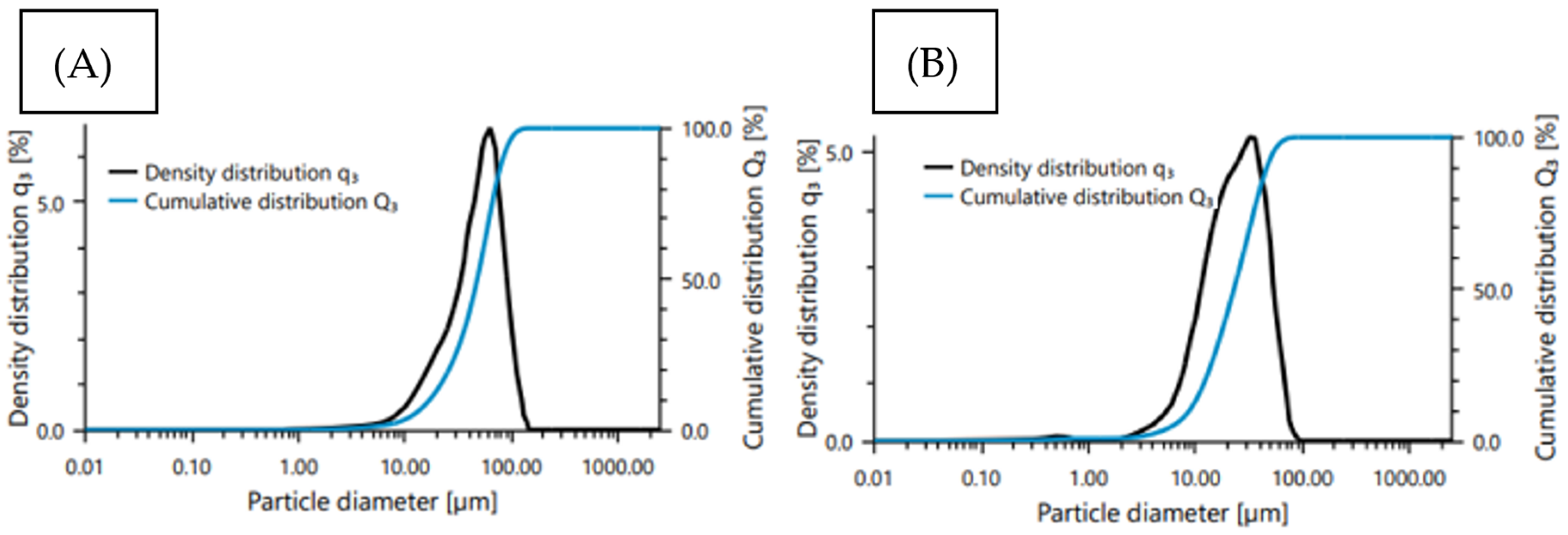
Commercially available aluminum and titanium metal powders were used in the tests. The particle size analysis of the feedstock powder was carried out by laser diffraction using Anton Paar PSA-1190 granulometer (Anton Paar GmbH, Graz, Austria). In the case of aluminum powder, the particle size was found to be in the D10–D90 range between 10 and 46 µm, with a mean size of 26.7 µm (
Figure 1A). For titanium powder, D10–D90 was 16–82 µm with a mean size of D50 47 µm (
Figure 1B).
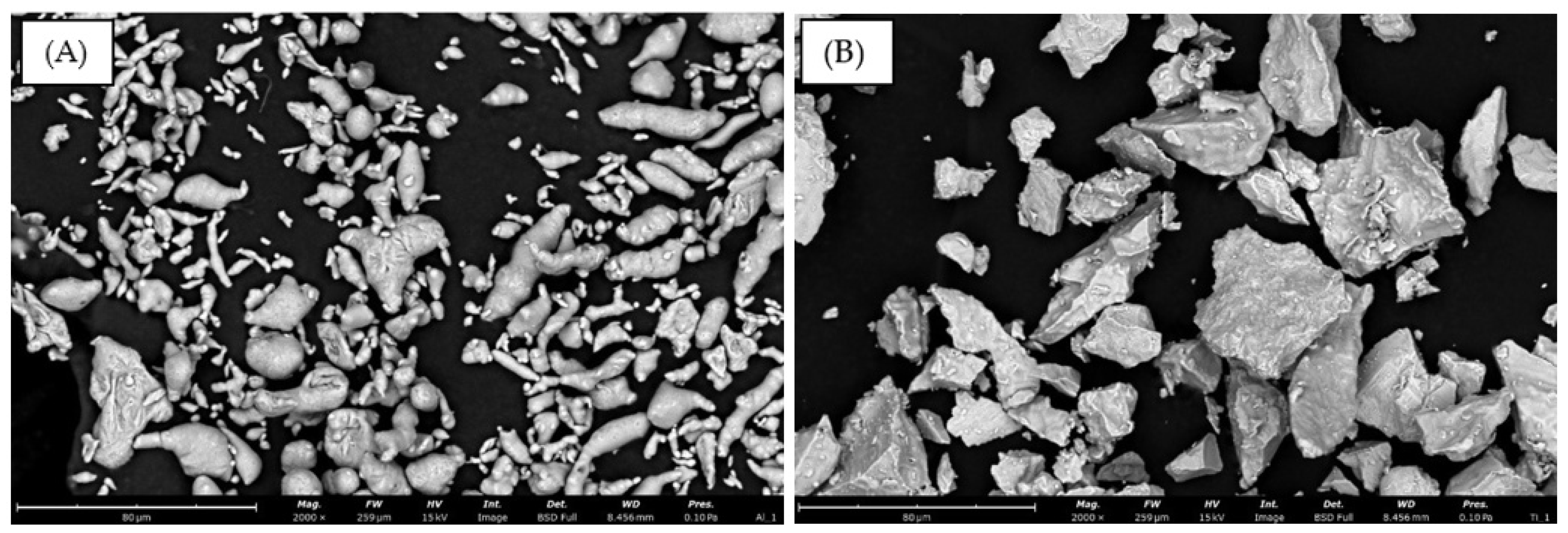
The powders differed in their morphology. The aluminum powder’s morphology shows irregular oblong and oval particles (
Figure 2A). The titanium powder, whose morphology shows variously shaped polyhedral solids with rough edges (
Figure 2B), was used as an admixture strengthening the aluminum coating.
The coatings were produced using low-pressure cold gas spraying (LPCS) in the Department of Plastic Working, Metrology, and Welding at Wrocław University of Science and Technology. The DYMET 413 device (Dycomet Europe BV, Akkrum, The Netherlands), made by Obninsk Centre for Powder Spraying, was used. The coatings were deposited on an aluminum substrate (AA1350) using various mass fractions of the metal powders. Optimal spraying parameters (
Table 1) and the mass fractions of the fed powders had been experimentally determined. Preliminary investigations showed that the coatings in which the mass fractions amounted to 60% Ti and 70% Ti (the rest being the aluminum matrix) were characterized by the highest coverage rate and the optimal morphology. The powders were mixed by means of a laboratory stirrer for 60 min.
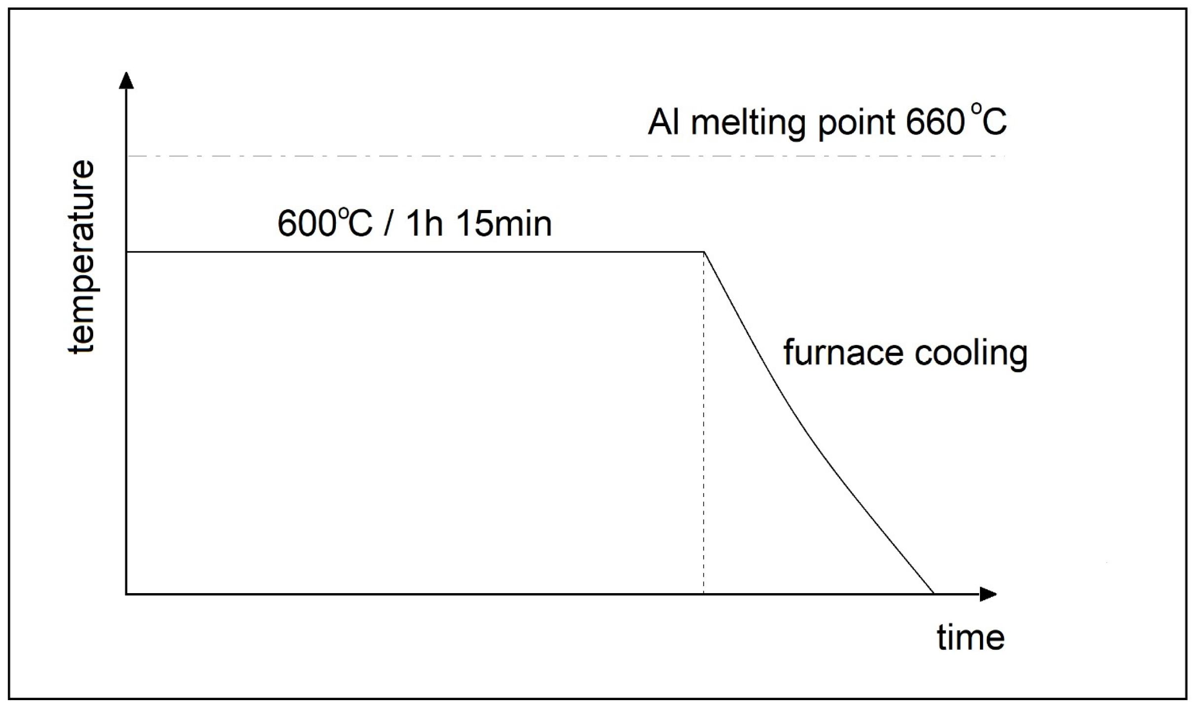
In order to obtain a metallic phase, the Ti–Al coatings were heat treated in laboratory resistance furnaces. The heat treatment was conducted without a protective atmosphere. The process covered annealing at the temperature of 600 °C for 1 h and 15 min, followed by slow furnace cooling. The temperature and time had been selected on the basis of the literature and an experiment. A temperature-time diagram for the heat treatment of composite coatings Ti60-Al40 and Ti70-Al30 is presented in
Figure 3.
The preparation of the samples consisted of grinding and polishing. Abrasive paper of grades 240, 600, 800, and 1200 was used in succession. This was followed by polishing using a polishing cloth and 6 and 1 µm diamond paste suspensions.
Metallographic examinations of the morphology of the metal powders and the microstructure of the coatings were carried out using an electron scanning microscope (SEM Thermo Scientific Phenom XL). In order to confirm the presence of intermetallic phases, the microstructure of the coatings was examined under a Hitachi H-800 transmission electron microscope (Hitachi, Tokyo, Japan) using an accelerating voltage of 150 kV and the focused ion beam (FIB) thinning procedure.
An X-ray diffraction (XRD) analysis was carried out to evaluate the phases occurring in the coatings before and after the heat treatment. For this purpose, an Ultima IV (Rigaku, Tokyo, Japan) diffractometer with a CuKα lamp, with a scanning range of 10–100 °C and a step of 0.05, was used. Quality examinations consisted of an energy-dispersive X-ray spectroscopy (EDS) analysis. A JEOL JSM-6610 A scanning electron microscope equipped with the EDS Ex–230**BU system was used for this purpose.
Six Vickers microhardness measurements under a load of 10 g (0.098 N), 500 g (4.9 N), and 1000 g (9.81 N) were performed. A Leco LM-248AT microhardness tester (St. Joseph, MI, USA) was used for this purpose. The measurements were conducted in accordance with the standard.
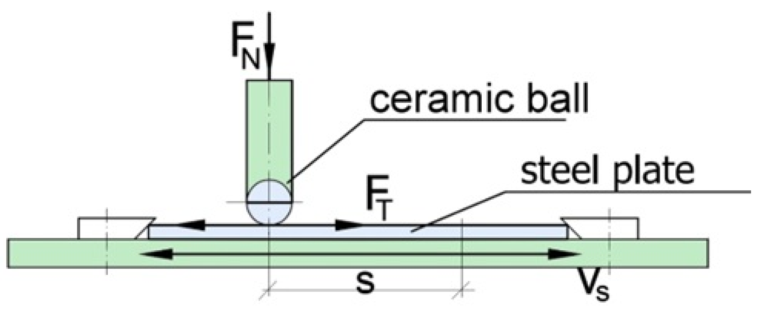
Tribological tests of the friction process were carried out on a test rig (
Figure 4) built in the Department of Machine Construction Fundamentals and Tribology. The test rig is suitable for conducting sliding friction-in-alternating motion tests [
22]. Tribological properties were determined using a ceramic (SiC) ball pressed with force Fn against a steel plate with the tested coating placed on it. For the analysis, three series of measurements, in which a sample with a coating mounted on a movable carriage would perform 200 motion cycles, were carried out. A motion cycle consists of two motions (to and fro) at velocity v
smax = 5 mm/s) in both directions. The time of motion in each of the directions amounted to 0.4 s. The friction junction load amounted to 20 N. Ceramic bearing balls with d = 4 mm were used in the tests. The tests were conducted in dry friction conditions. Prior to taking measurements, the surfaces of the coatings were ground, polished, and cleaned in order to make them homogenous. A Leica DCM8 profilometer (Leica, Wetzlar, Germany) was used to examine the geometric structure of the surfaces after the friction processes.
3. Results
3.1. Phase Identification
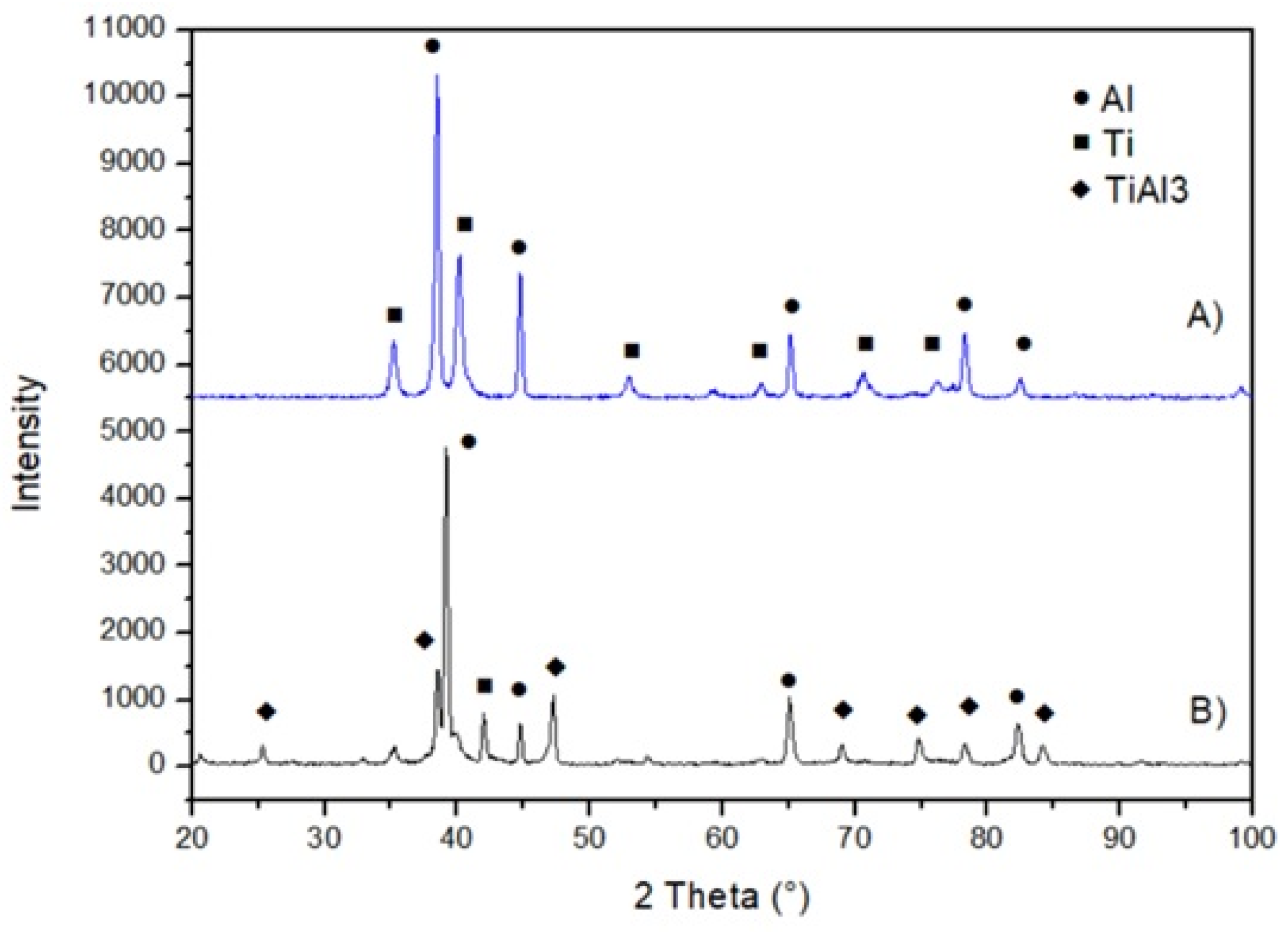
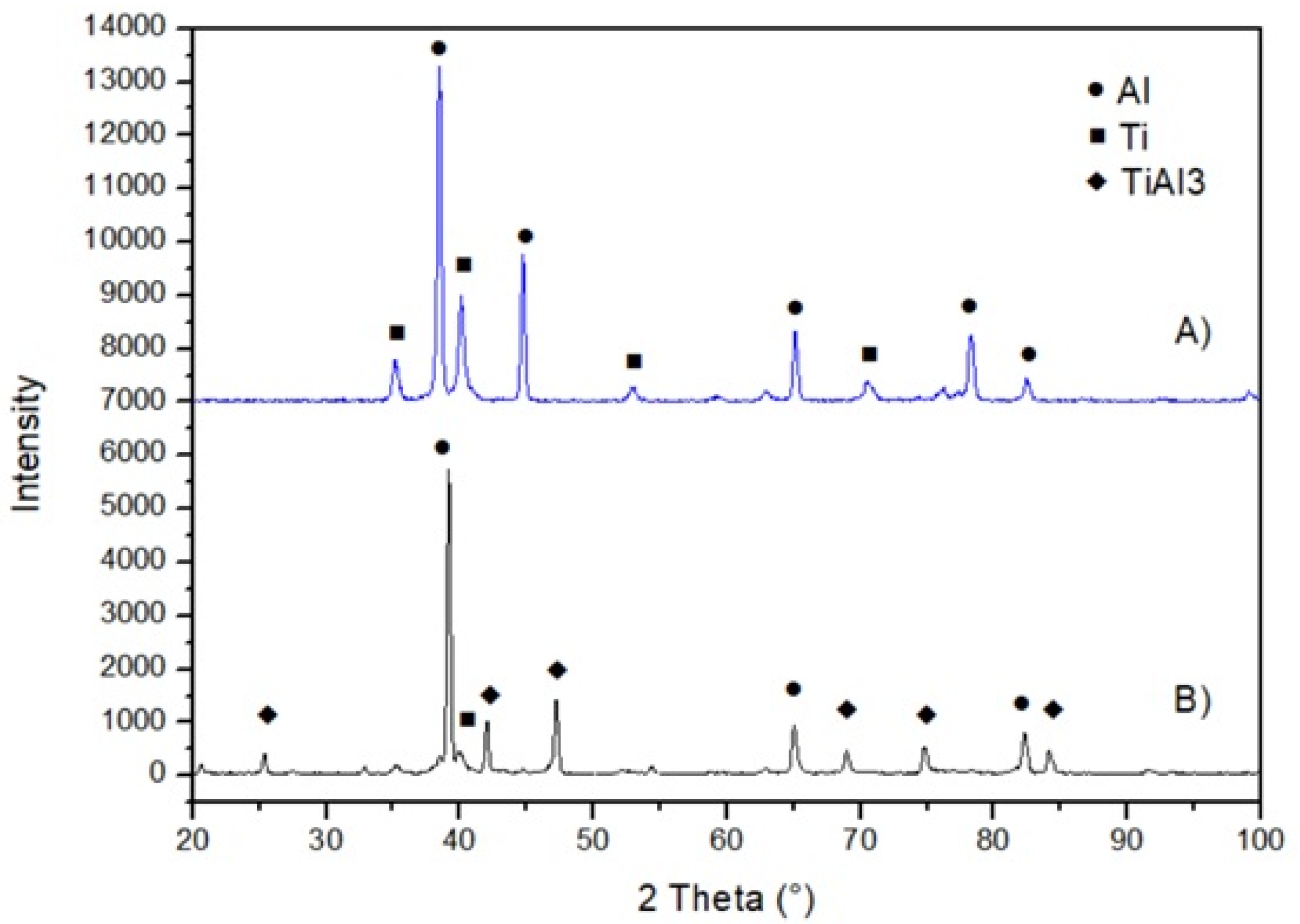
XRD investigations were carried out to assess the effect of heat treatment on the possibility of intermetallic phase forming in Ti–Al coatings. In the two cases, an analysis of the diffraction images of the coatings after the latter had been applied using the LPCS method shows the presence of energy spectra originating from solely pure titanium and aluminum phases (
Figure 5 and
Figure 6). In both cases, the analyses of the heat-treated coatings revealed peaks associated with titanium and aluminum, and also peaks associated with the presence of an intercrystalline phase in the structure. According to the literature on the subject, the latter peaks indicate a phase expressed by the stoichiometric formula TiAl
3 [
23,
24]. The TiAl
3 structure was observed in the case of the first heat treatment after 3 h at the temperature of 650 °C. Furthermore, using the Rietveld method, it was found that as the heat treatment time increased, the fraction of this intermetallic phase in the structure also increased [
1,
2]. It was concluded that as a result of thermal energy supply, the titanium particles deposited in the aluminum matrix brought about a reaction (via diffusion) with the aluminum particles, whereby a TiAl
3 phase formed.
3.2. Investigations of Microstructure and Chemical Composition
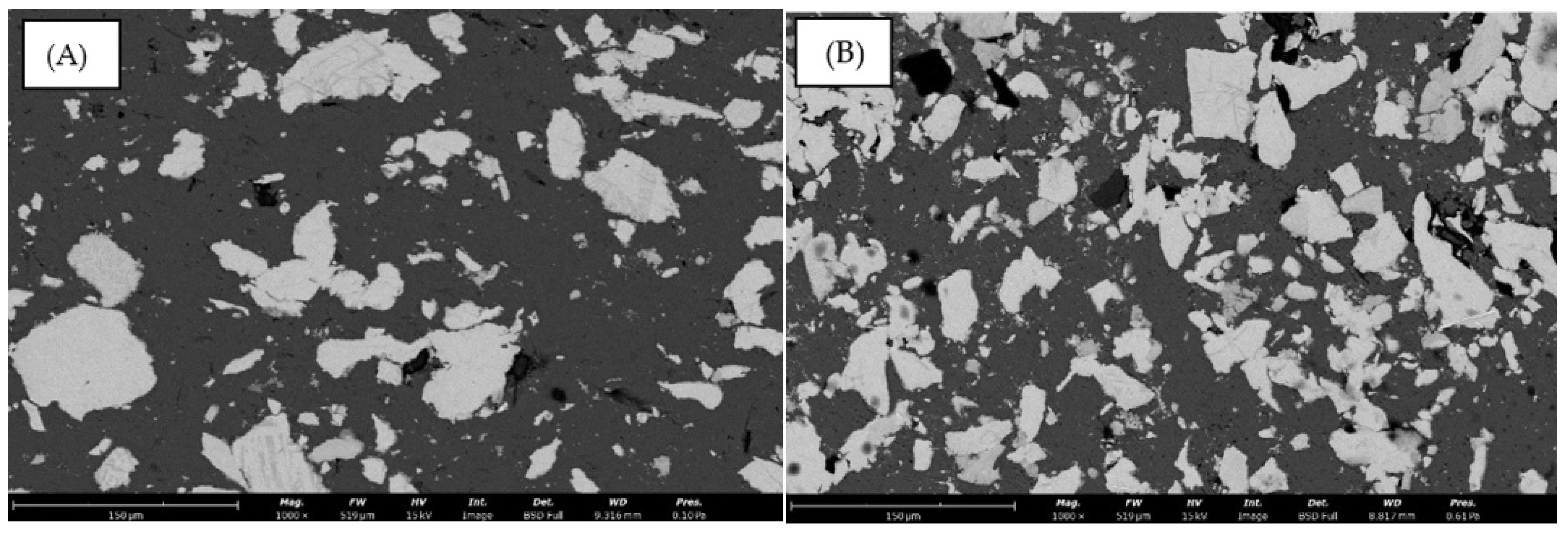
Examinations of the microstructure of the Ti–Al composite coatings before and after heat treatment revealed a compact homogenous structure (
Figure 7A,B). The coatings were found to adhere continuously to the substrate, and small porosity in their structure was discovered. The incompletely formed light particles of hard titanium (the light phase) were immersed in the matrix of soft plastic aluminum (the dark phase), forming a composite coating with a high degree of fit. In the coatings with less titanium, the titanium phase particles were found to be uniformly distributed, whereas in the case of more titanium, the titanium particles formed interconnected clusters.
Examinations of the microstructure of the coatings after heat treatment revealed an additional phase to be present in the titanium particles (
Figure 8A,B). The observed separations appear at the boundaries of Ti particles and have the form of a surrounding band about 10 µm thick. The increased TiAl
3 fraction appears in the places where, before heat treatment, there had been no porosity between the particles of Ti and Al. This defect is due to the absence of contact between the particles of the matrix and those of the strengthening addition in the composite coating before heat treatment. It is concluded that no intermetallic phase formed locally under the action of high temperature because diffusion could not take place.
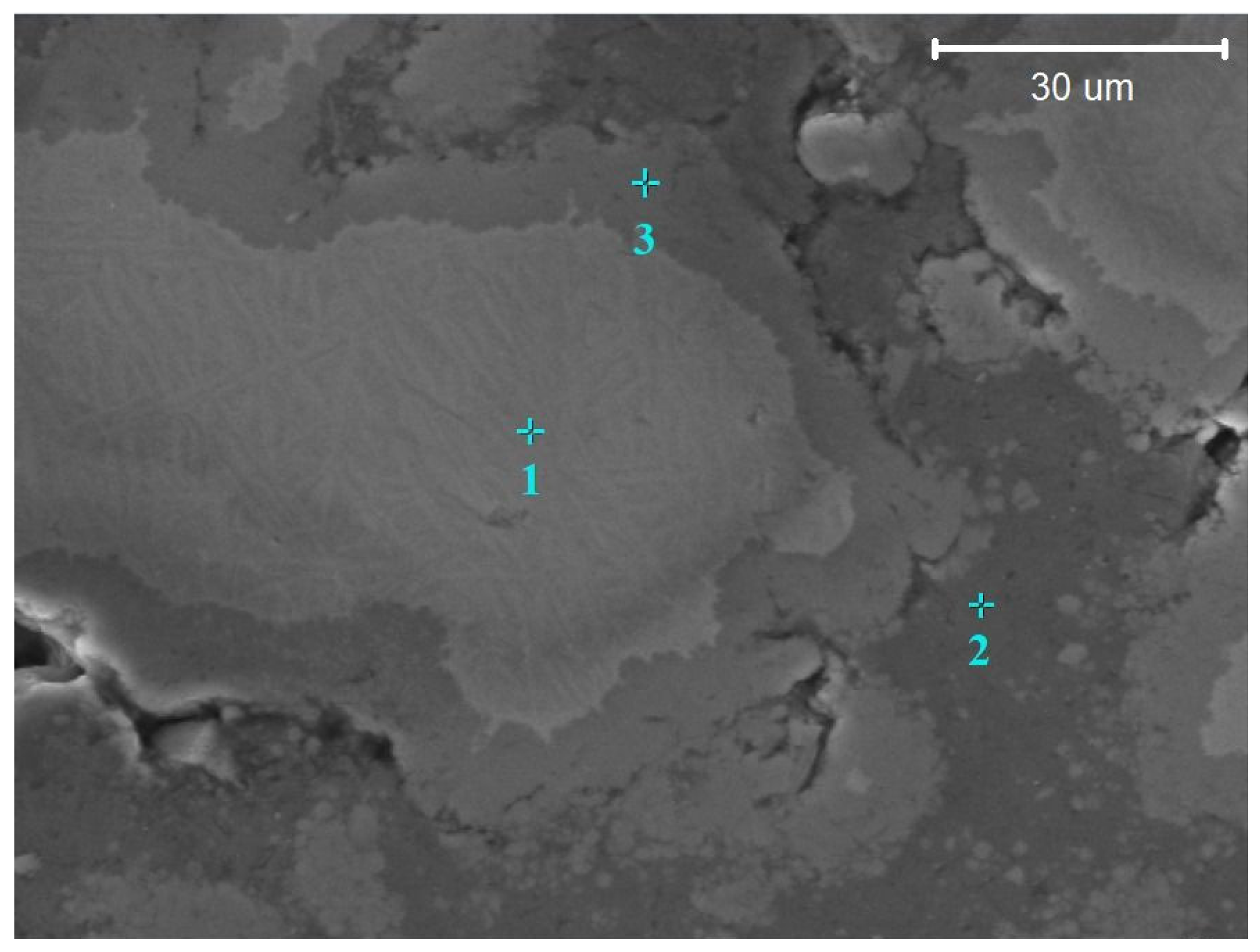
An analysis of the chemical composition by means of an EDS detector confirmed the increase in aluminum content in this area, which proves that an intermetallic phase formed in the titanium particles in the coatings as a result of heat treatment (
Figure 9). The results of the chemical composition analysis for the marked points are presented in
Table 2. On the basis of the signal excited by an electron beam in the indicated area, the chemical composition and spectrum of point 006 were obtained, whereby the Al fraction and the Ti fraction there were determined to amount to 63.79% and 36.21%, respectively. The above Al and Ti fractions correspond to, in terms of atomic mass, the aluminum and titanium content in the TiAl
3 phase. It is confirmed by the Ti–Al phase equilibrium diagram.
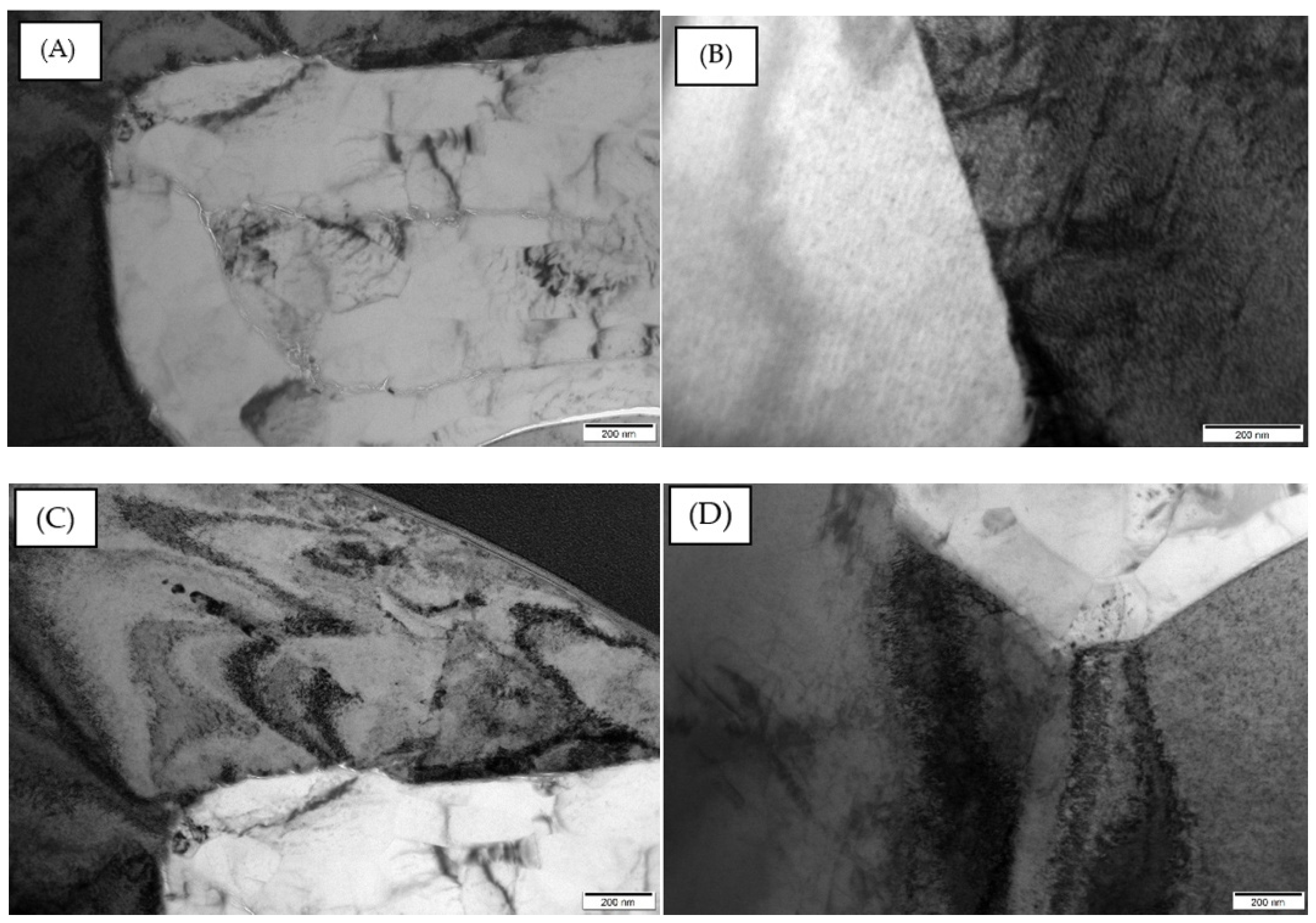
The transmission electron microscopy of the composite coatings after LPCS revealed a diphase structure (
Figure 10A,B). Both the lighter aluminum grains and the darker titanium grains exhibit a coarse-grained structure and a high degree of cohesion. A large accumulation of dislocations of various characteristics is visible in the titanium grains area. Dislocations are observed both within titanium grains, in the form of semicircles oriented towards the interphase boundary, and in the form of dislocations piled up on the interphase boundaries (
Figure 10C,D). In the case of aluminum grains, dislocation pile-ups are visible on the same-sign aluminum boundaries.
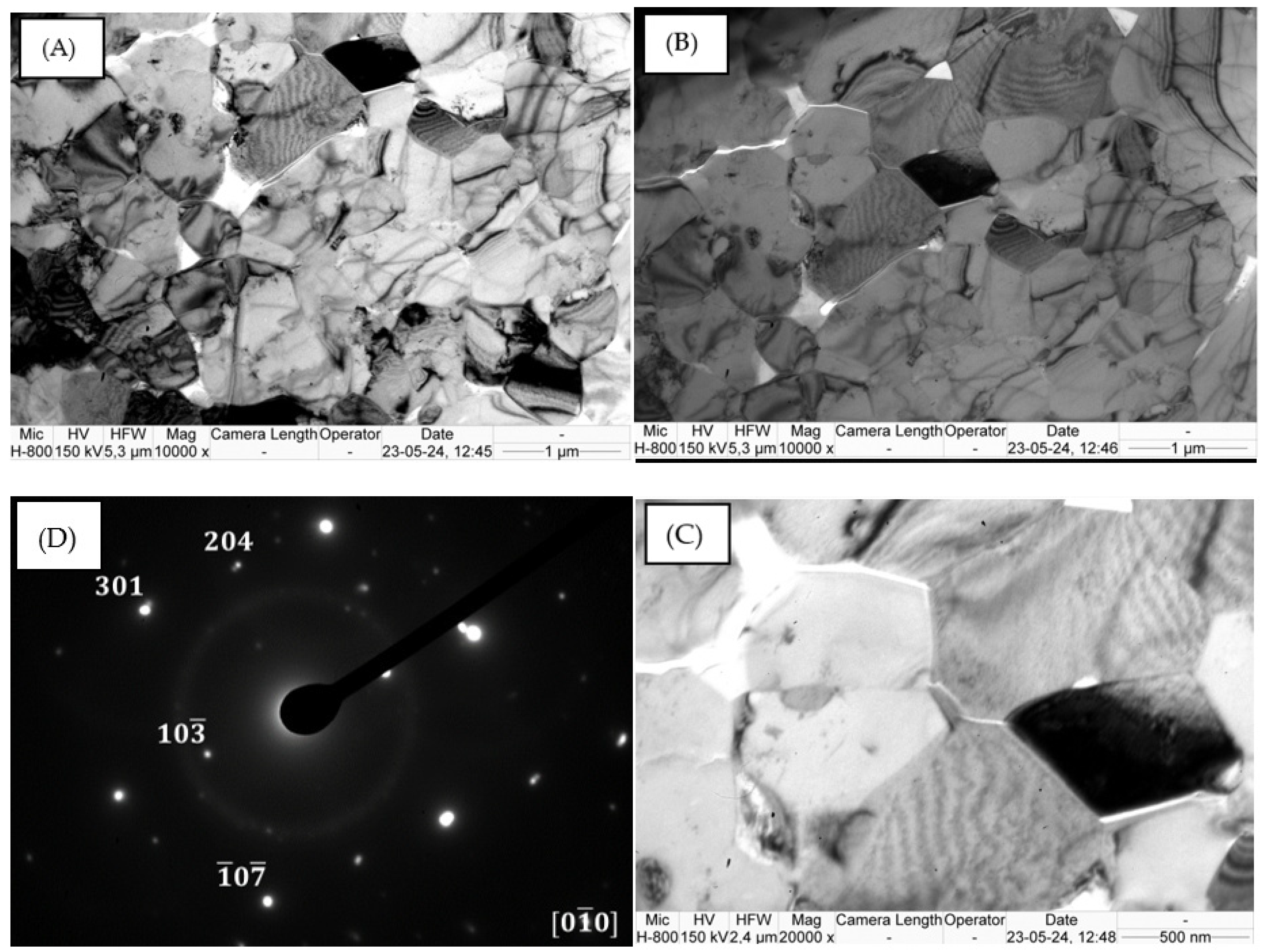
The examinations of the Ti–Al composite coatings after heat treatment revealed a refined structure in the zone where the TiAl
3 intermetallic phase occurred (
Figure 11A,B). The grains range in size from about 500 nm to 1 µm. A small porosity value was found between the equiaxial grains of the TiAl
3 intermetallic phase, which could have been caused by thermal stresses arising during diffusion processes and the formation of the intermetallic phase (
Figure 11C). The diffraction registered in this area confirms the presence of the Ti–Al
3 intermetallic phase (
Figure 11D) [
25].
3.3. Hardness
The average microhardness values measured on cross-sections and the determined standard deviations for the tested materials are presented in
Table 3. The highest noted microhardness for the Ti60Al40 coating after heat treatment amounts to 64HV0.5 and 60HV1. The lowest microhardness values are 51HV0.5 and 46HV1. The discrepancies between the microhardness results could be due to the porosity. It should be noted that the TiAl
3 phase appears around titanium grains in the tested coatings. Hence when the area in which hardness was measured consisted of mainly Ti grains and phase TiAl
3, the result was considerably higher than that for the coating’s area containing more Al grains. The average microhardness of the Ti60-Al40 coating produced by LPCS, after treatment, amounted to 57HV0.5 and 51HV1.
For the Ti70Al30 coating, the highest microhardness amounts to 94HV0.5 and 89HV1, while the lowest microhardness is equal to 78HV0.5 and 71HV1, respectively. The differences in the outlying measurements between the load of 1000 g and that of 500 g amount to 18HV1 and 16HV0.5. Similarly, as in the Ti60-Al40 coating, the microhardness value depends on the area in which the measurement was made. The average microhardness for the Ti70-Al30 coating amounts to 78HV0.5 and 85HV1.
In addition, measurements of the microhardness of the formed TiAl
3 phase taken from the Ti70Al30 sample were carried out. Loads of 500 g and 1000 g were selected as they allowed consideration of the microstructural inhomogeneity and assessment of the influence of the TiAl
3 phase. The 10 g hardness test was conducted solely to determine the hardness of the TiAl
3 phase due to its very narrow area. Since the tested area occurred solely on the boundaries of titanium grains, the load of 10 g was adopted. For the series of six measurements, the average result amounted to 450HV0.01. This is consistent with the values reported for the tested intermetallic phase in the literature [
26].
3.4. Coefficient of Friction
Tribological tests were carried out both before and after heat treatment [
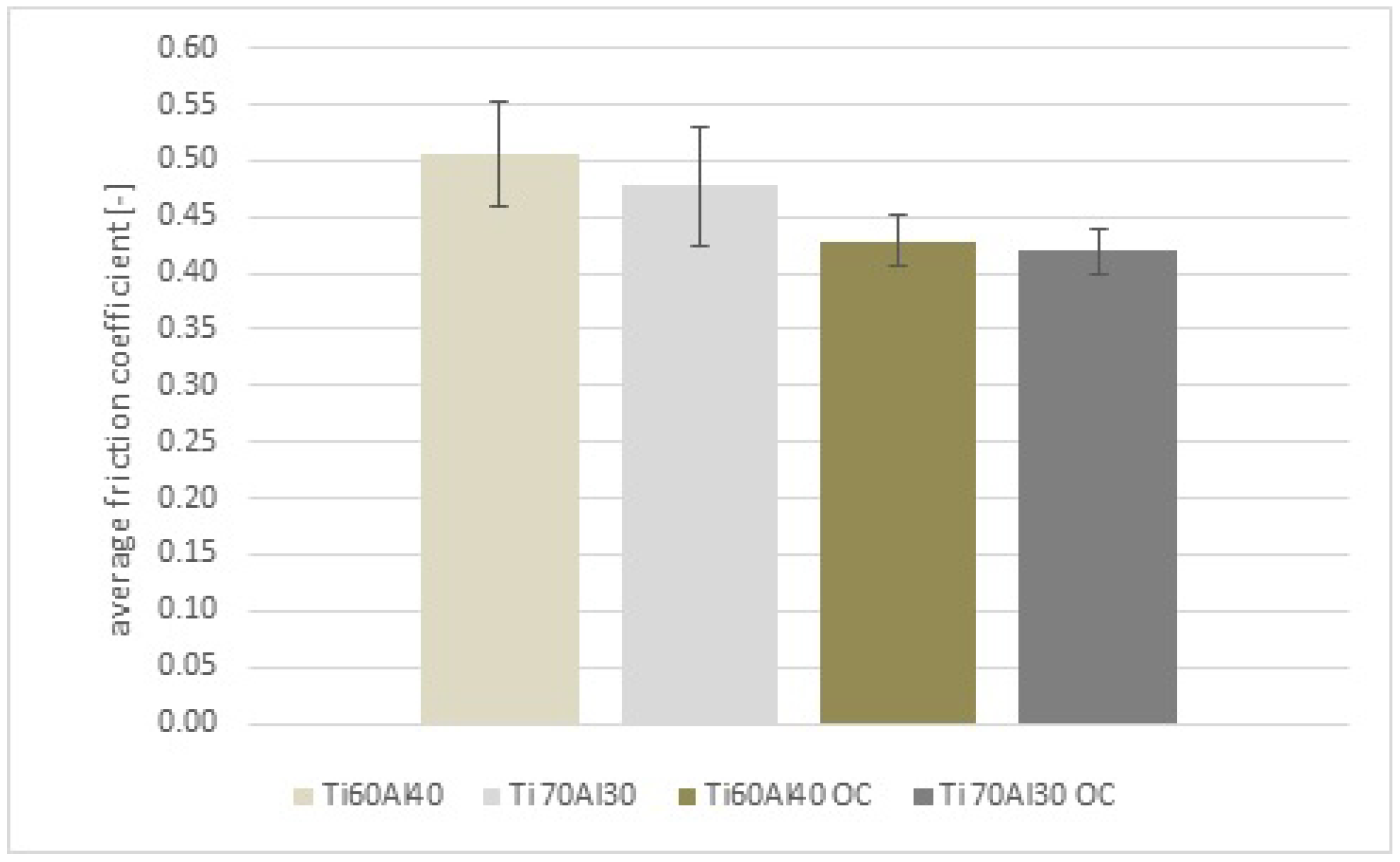
26]. Their results for the load of 20 N showed that a percentage increase in titanium content in the coating caused a decrease in the coefficient of friction (
Figure 12). The increased presence of phase Ti results in the worsening of the thermal properties and a decrease in the friction coefficient to the value of 0.48 in the Ti70Al30 coating in comparison with the value of 0.5 for the Ti60Al40 coating. The friction coefficient results for the heat-treated composite coatings containing intermetallic phase TiAl
3 also showed a decrease in the coefficient of friction. The Ti percentage content in the heat-treated coating showed a reverse tendency. A minimal decrease in the friction coefficient value from 0.43 for the 60%Ti samples to 0.42 for the 70%Ti samples was noted.
3.5. Profilometric Tests
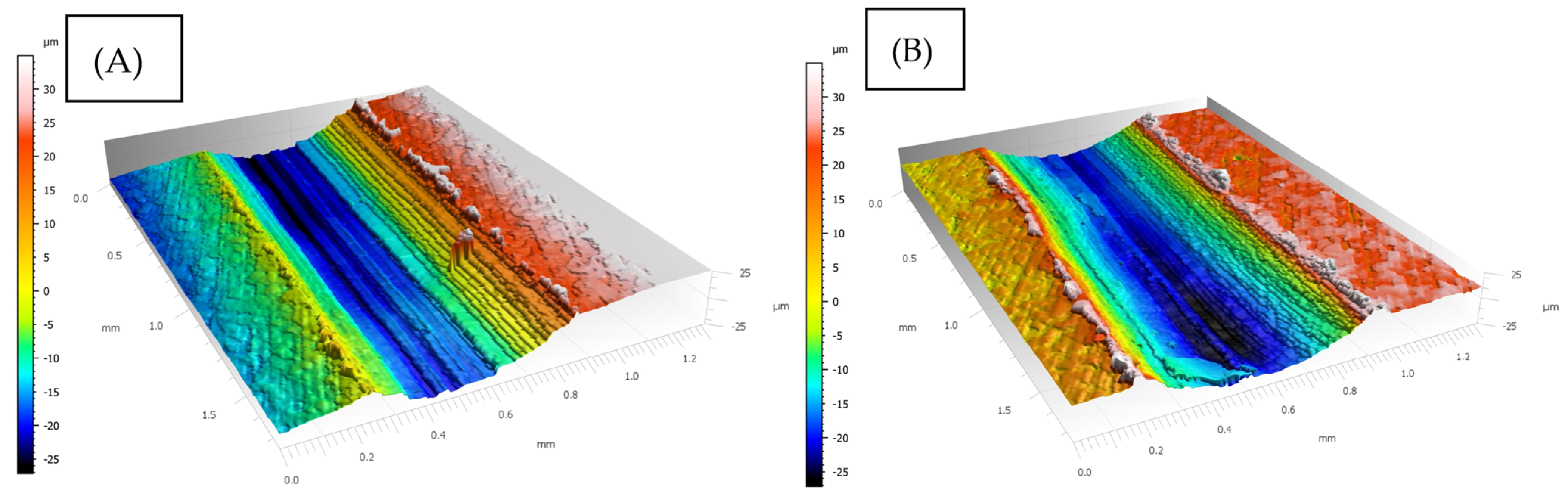
An analysis of the surface topography of the coatings after friction against the ceramic ball showed uniform coating material wear. On the basis of the friction track, the wearing of the coating can be classified as belonging to the plastic deformation mechanism. In both samples, a high degree of yield, with no chips or traces of coating material cutting, is noted (
Figure 13). Considering that the friction coefficients differed only slightly, the samples should have had similar topographies. This was confirmed by the test results. The greater material wear at the groove’s beginning and end, visible in the profilometric image, is due to instantaneous static friction caused by the change in the direction of the moving ball. The groove, in the case of the coating with a lower titanium content, has a larger percentage of flash. This can be explained by a higher Al content, contributing to plasticity, in comparison with the Ti70-Al30 sample.
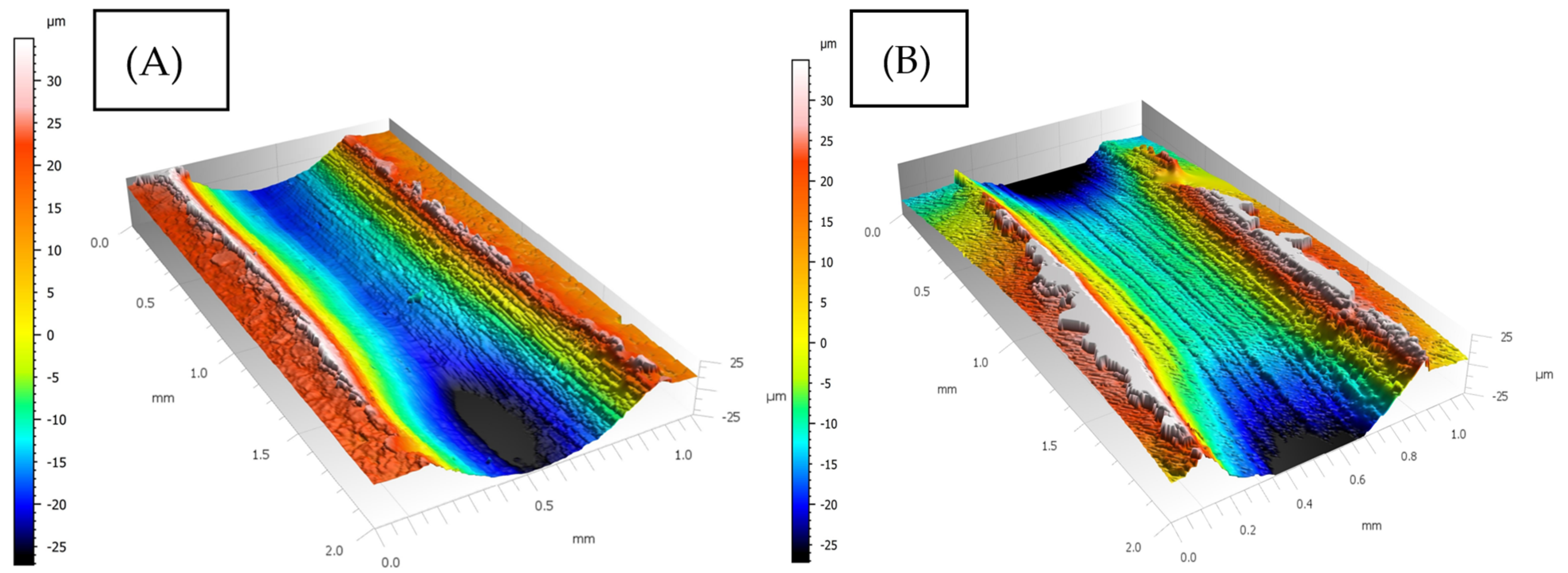
The topography of the thermally treated samples subjected to tribological tests carried out in similar conditions as in the case of the untreated samples is shown in
Figure 14. In the middle part of samples Ti60Al40 OC and Ti70Al30 OC the material wear is smaller in comparison with the untreated samples. At the same time, a larger percentage of flash is noted for the two tested samples. In the case of the Ti60Al40 OC sample, increased abrasive wear, in comparison with the sample with a larger amount of Ti and phase TiAl
3, is observed.
An analysis of the depths of the grooves left after tribological tests prior to thermal treatment showed that increasing the Ti content had no significant effect on the depth of the flash. The reading for both samples amounted to about 30 µm. The width of the samples was estimated at about 0.70 mm for the Ti60Al40 sample and 0.65 for the Ti70Al30 sample (
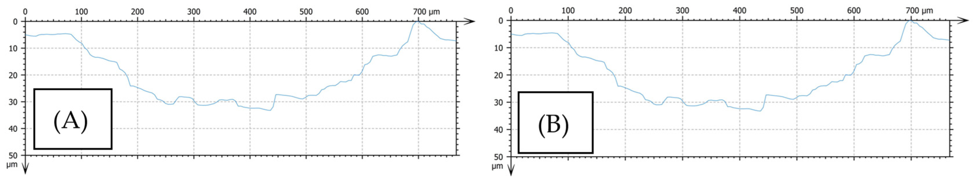
Figure 15). Whereas after the heat treatment the analysis showed that the titanium and TiAl
3 phase addition contributes to a decrease in the coefficient of friction and to the degradation of the material’s surface. This effect is noticeable in the reading of flash depth, which in the maximum depths amounted on average to 26 µm for the Ti60Al40 coating. The average flash reading for the Ti70Al30 coating amounted to 16 µm. (
Figure 16). Moreover, the friction track width was measured. It amounts to about 0.75 mm and 0.60 mm for the Ti60Al40 coating and the Ti70Al30 coating, respectively.
3.6. Microscopic Examinations of Groove
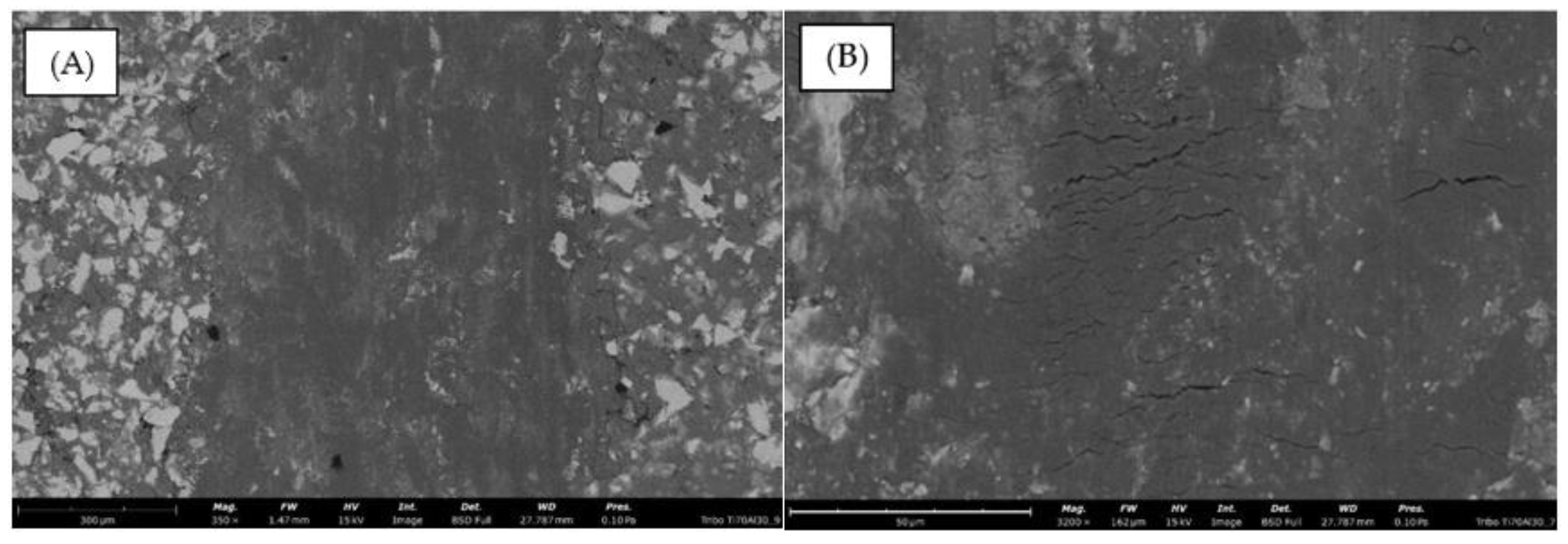
SEM examinations of the groove revealed that the investigated coatings had undergone plastic deformation (
Figure 17A,B). The abrasions are characterized by the plastic deformation of the material in contact with the ball. Smaller close-ups of the abrasions (
Figure 16) show a higher aluminum matrix fraction than that observed in this area before the test. This can be explained by the Orowan mechanism because of the presence of Ti and TiAl
3 layers, which are harder than the matrix (also, their moduli of shear are higher) and so exhibit low cohesion with the latter. Hence, during deformation it is mainly the Al particles that are dislocated and smeared over the whole volume of the groove. A greater close-up reveals gaps in the matrix structure (
Figure 18A,B). Since this defect occurs between undeformed Ti and TiAl
3 particles, it is concluded that it is in the Al particles that undergo deformation that stress pile-ups occur.
4. Discussion
The conducted experiments on Ti–Al composite coatings revealed several key findings regarding the influence of powder composition, heat treatment, and mechanical testing on the resulting material properties.
Firstly, the X-ray diffraction (XRD) analysis confirmed the presence of intermetallic phases in the coatings after heat treatment, specifically the TiAl3 phase, which plays a critical role in enhancing the strength and thermal stability of the coatings. The formation of this phase, as detected through diffraction peaks, aligns with the literature, indicating the diffusion of titanium and aluminum particles at elevated temperatures. This diffusion process is crucial for forming a homogenous intermetallic phase, but it was also noted that areas lacking particle contact before heat treatment did not exhibit the desired intermetallic phase formation.
The microstructural examinations further supported these findings, showing that heat treatment improved the compactness and homogeneity of the coatings; however, the presence of porosity and incomplete particle bonding prior to heat treatment suggests that the LPCS process could benefit from further optimization to reduce these defects. The observed TiAl3 phase surrounding titanium particles enhances the mechanical properties of the coatings, particularly in terms of hardness and wear resistance; however, the uneven distribution of titanium in coatings with higher Ti content (70% Ti) resulted in clustering, which may negatively impact the overall uniformity of the mechanical properties.
Microhardness measurements revealed that the hardness of the coatings was largely dependent on the distribution of the TiAl3 phase and the overall composition of the coating. Coatings with higher titanium content exhibited higher hardness, but variations in hardness measurements due to porosity highlight the need for improved coating uniformity.
Tribological testing provided valuable insights into the wear behavior of the coatings. The results demonstrated that increasing titanium content reduced the coefficient of friction, with a more pronounced effect observed after heat treatment due to the formation of intermetallic phases. This reduction in friction coefficient can be attributed to the increased hardness and presence of TiAl3, which provides better resistance to wear. Profilometric analyses of the friction tracks showed that thermal treatment also contributed to a decrease in material degradation, with less severe wear and reduced groove depth observed in the heat-treated samples.
Overall, the results indicate that the addition of titanium to aluminum coatings significantly improves their mechanical and tribological properties, particularly when optimized through heat treatment; however, the uneven distribution of titanium particles and the presence of porosity in the coatings highlight areas for improvement in the LPCS process.
5. Conclusions
Based on the conducted research, it can be concluded that the heat treatment modification involving the addition of titanium to aluminum coatings led to a significant improvement in their mechanical properties. In particular, there was an increase in hardness and wear resistance. The main factor improving the performance of the tested coatings with a composite structure is the formation of a TiAl
3 intermetallic phase. This study also indicated that the formation of intermetallic structures can proceed during a much shorter heat treatment than previously proposed in the literature [
25]. Using the LPCS process, it is possible to produce coatings with beneficial properties, but may still be able to utilize further optimization, such as heat treatment, to change the microstructure, leading to improved mechanical properties. Studies have also shown the possibility of reducing porosity and providing a more uniform distribution of reinforcing phases. The results of this study lead to the following key conclusions:
The formation of the intermetallic TiAl3 phase significantly increased the hardness to 450HV0.01, leading to considerable strengthening of the composite structure. This resulted in improved hardness and wear resistance throughout the entire coating, compared to Ti–Al coatings that were not subjected to heat treatment.
Microstructure analysis of Ti–Al composite coatings, both before and after heat treatment, revealed a compact, homogeneous structure with good adhesion to the substrate and low porosity. Hard titanium particles were embedded in a soft aluminum matrix. In coatings with lower titanium content, the particles were uniformly distributed, while higher titanium content led to clustering. After heat treatment, an additional phase appeared in the titanium. An increase in TiAl3 was observed in previously non-porous areas, indicating the absence of intermetallic phase formation due to limited diffusion before heat treatment.
An increase in titanium content in the coatings resulted in a reduction in the coefficient of friction, both before and after heat treatment. For the Ti70Al30 coating, the coefficient of friction was 0.48 compared to 0.5 for Ti60Al40. After heat treatment, coatings containing the TiAl3 phase also showed a decrease in the coefficient of friction, with a slight reduction observed from 0.43 for Ti60Al40 to 0.42 for Ti70Al30.
SEM analysis of the groove indicated that the coatings underwent plastic deformation, with Al particles being dislocated and smeared across the groove due to the Orowan mechanism. This occurred due to the presence of harder Ti and TiAl3 particles, which had lower cohesion with the aluminum matrix. Gaps observed in the matrix structure between undeformed Ti and TiAl3 particles suggest that stress accumulation occurs primarily in the deformed Al particles.
In conclusion, Ti–Al composite coatings applied using the LPCS method can be successfully optimized through heat treatment to modify their properties for specific applications; however, it is important to note that changes in the microstructure, including the formation of the additional strengthening intermetallic phase TiAl3, may also lead to negative effects, such as structural discontinuities due to porosity.
Future work should focus on refining the spraying parameters and heat treatment processes to enhance coating quality and ensure consistent mechanical properties across the entire coated surface. These findings provide a solid foundation for further research into the application of composite coatings in industries requiring high-strength, wear-resistant materials.


 ,
, 


