Abstract
NaNbO3-based ferroelectric composites are regarded as a highly promising typical energy storage material. In this work, 0.02xMnO2−(1−x)NaNbO3−xBi0.5Na0.5TiO3 composites were prepared by the solid-state sintering method and their microstructure, energy storage performance, and temperature stability were analyzed. As observed by the SEM images, the addition of Bi0.5Na0.5TiO3 to NaNbO3 in appropriate amounts can effectively suppress grain growth, which is beneficial for improving the breakdown field strength. When x = 0.3, an optimal value of 210 kV/cm is achieved. Meanwhile, as 2θ = 33.2°, the most intense XRD peak can be observed, indicating excellent solid solubility between the phase components. Consequently, 0.006MnO2–0.7NaNbO3–0.3Bi0.5Na0.5TiO3 composites demonstrated an impressive discharging storage density of 2.464 J/cm3 and a considerable energy storage efficiency of 85.8%. In addition, within the temperature range of 30–80 °C, the fluctuation in energy storage density remains below 10%. All the above performances indicate that this type of material exhibits excellent practicality in the field of pulse power supply.
1. Introduction
As the core component of pulse high-voltage power supplies, ferroelectric energy storage ceramic materials exhibit promising application prospects in the field of power electronics, particularly in areas such as electric vehicles, high-voltage ionization and bacterial inactivation, owing to their exceptional fast charging and discharging capabilities, as well as their temperature stability [1,2]. Currently, lead-containing perovskite ceramics remain the most extensively researched ferroelectric materials [3,4]. However, given lead’s toxicity as a metal, it poses a significant threat to human health [5,6]. As a result, researchers are focused on seeking lead-free alternatives as a means of circumventing this issue [7].
It is widely recognized that the charging density (Wc), discharging density (Wd), and charging/discharging efficiency (ŋ) of energy storage dielectrics can be estimated by the equations below:
where E stands for electric field, P denotes polarization, Pr represents residual polarization and Ps signifies saturation polarization. The formulas demonstrate that high breakdown strength (Eb), large Ps, and small Pr are the keys to improving energy storage performance. Currently, the forefront of research in lead-free energy storage ceramics encompasses AgNbO3 (AN)-based, Sr0.7Bi0.2TiO3 (SBT)-based and NaNbO3 (NN)-based materials. The AN-based ceramics demonstrate large Wd; however, to prevent alterations in the valence state of silver ions during the sintering process, a specific sintering atmosphere is necessary [8,9]. As for the SBT-based materials, praiseworthy ferroelectric relaxation behavior is readily achievable, but their low Eb constrains the improvement of energy density [9,10]. In comparison to the aforementioned types, NN-based ceramics exhibit outstanding energy storage capabilities, lower production costs, and straightforward manufacturing processes [11,12]. Nevertheless, their application in energy storage still faces limitations of high Pr and small Eb [13,14]. A careful analysis of the scientific literature on energy storage ceramics reveals that ionic doping has the potential to disrupt the long-range order of ferroelectrics, thereby significantly diminishing the remnant polarization and bolstering the energy storage performance [15]. As an example, the incorporation of manganese ions into AgNbO3 effectively decreased the Pr of the ceramic to 0.8 μC/cm2, compared to 4.4 μC/cm2 for the unadulterated counterpart. This is due to the replacement of manganese ions with niobium ions at site B, which triggers a change in lattice constants and increases internal stress, thereby elevating the ferroelectric polarization barrier and reducing the residual polarization strength [16]. It is foreseeable that incorporating an appropriate amount of manganese ions into ferroelectric energy storage materials will result in a narrower hysteresis loop, ultimately enhancing energy storage efficiency. Furthermore, multi-phase composite modification is also an effective method to enhance the energy storage performance of materials [6,17]. According to reports, in some NaNbO3-based composites, the incorporation of bismuth ions facilitates a reduction in sintering temperature. This reduction is beneficial for improving structural defects caused by the volatilization of sodium ions and strengthening the Eb [18,19]. Furthermore, the replacement of Bi and Na ions can cause fluctuations in local components, thereby contributing to the reduction in the Pr of the composite [20]. From this, it can be inferred that introducing other bismuth-containing ferroelectric phases into NaNbO3 can also improve the energy storage performance. Notably, (Bi0.5Na0.5)TiO3 (BNT), as a prototypical expected material, demonstrates an impressive Ps value of 43 μC/cm2, rendering it highly appealing [21].
Taking into account the impact of the above ions and phase composition, in this work, we fabricated 0.02xMnO2−(1−x)NaNbO3−xBi0.5Na0.5TiO3 composites and studied their sintering characteristics, microstructure, energy storage and discharging performance.
2. Materials and Methods
2.1. Preparation of M–NN–xBNT Samples
Polycrystalline ceramic samples of 0.02xMnO2−(1−x)NaNbO3−xBi0.5Na0.5TiO3 (M–NN–xBNT, x = 0, 0.2, 0.3, 0.4, 0.5 and 1) were prepared by solid-state sintering method. The components used were weighed based on the formula provided, which included Na2CO3 (99.5%), Nb2O5 (99.9%), TiO2 (99.0%), Bi2O3 (99.9%), and MnO2 (99.5%), and all raw materials used are produced by Aladdin Reagent Co., Ltd. (Shanghai, China). After ball milling, the mixture was dried and then heated at 700 °C for 3 h, followed by a second ball milling. After drying, the powder was pressed into compact green bodies under 200 MPa and kept sintering at 1050–1180 °C for 3 h. Finally, after polishing, the obtained ceramics were coated with high-temperature silver electrode and heat treated at 550 °C.
2.2. Characterization
The XRD curves were examined using X-ray diffraction (XRD, D8-Advance, Bruker AXS Inc., Madison, Germany). The grain surface images were captured via scanning electron microscope (SEM, SU8010, Hitachi Ltd., Tokyo, Japan). The P-E loops were analyzed with a ferroelectric tester (RTI-LC Π-100V, Radiant Technologies Inc., Burbank, CA, USA). The discharging behavior was evaluated using charging/discharging testing instrument (CDTS-10, JYJS Technology Co., Wuhan, China).
3. Results
Figure 1 displays the XRD patterns of M–NN–xBNT composites, revealing that all samples possess perovskite structures, as inferred from the peak characteristics. The most intense diffraction peak is noted at x = 0.3, indicating excellent solid solubility between the phase components. As illustrated in the enlarged view of Figure 2b, the (110) diffraction peak of ceramic exhibits an initial shift toward a low angle followed by a move towards a high angle with the addition of manganese content and BNT phase. This behavior means that the lattice of the samples initially expands and then contracts. The lattice expansion of ceramics for x = 0.2 or 0.3 should be primarily attributed to the replacement of larger Bi3+ (1.45 Å) for Na+ (1.39 Å) at site A, with the replacement of larger Mn2+ for Nb5+ (0.64 Å) and Ti4+ (0.605 Å) at site B also playing a role [14]. It is noteworthy that the valence states of manganese ions exhibit varied behavior across different preparation temperatures [22].
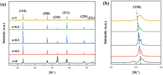
Figure 1.
(a) XRD curves of M–NN–xBNT composites and (b) the enlarged image of (110) diffraction peaks.
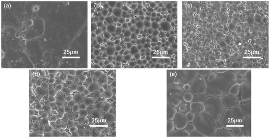
Figure 2.
The grain morphologies of the M–NN–xBNT composites: (a) x = 0; (b) x = 0.2; (c) x = 0.3; (d) x = 0.4, (e) x = 1.
In this study, the sintering temperatures of all samples fell within the range of 1050–1080 °C, enabling the reasonable coexistence of Mn2+ (0.83 Å) and Mn3+ (0.645 Å) in the M–NN–xBNT composites. When x = 0.4, the lattice shrinkage in the ceramic can be explained by Ti4+ replacing Nb5+ at site B. At this point, excessive doping of manganese ions begins to diminish its impact on lattice changes [23].
Figure 2 shows the SEM pictures of different M–NN–xBNT. It is evident that the grain distribution of all samples is compact and dense. The appropriate addition of BNT components and manganese elements is beneficial for refining grain size which reaches its minimum at x = 0.3. This suggests that the incorporation of BNT composition and manganese elements notably improves the introduction of grain boundaries, establishing a firm foundation to attain exceptional breakdown strength.
Figure 3 depicts the P-E loops and the corresponding energy storage properties of the M–NN–xBNT specimens. The introduction of appropriate amounts of BNT and manganese ions can cause changes in the lattice constant of the NN phase, leading to an increase in internal stress, which is not conducive to grain growth. As the grain size decreases, the grain boundaries increase, thereby enhancing the ferroelectric polarization barrier and making the hysteresis loop narrower [2]. Notably, the Eb reaches a maximum value of 210 kV/cm at x = 0.3, corroborating prior predictions derived from SEM patterns. Concurrently, Wd attains its peak value of 2.464 J/cm3, with a considerable energy storage efficiency of 85.8% achieved. The P-E loops of the samples under different external electric fields are displayed in Figure 3c. With the enhancement of the external electric field, both Pr and Pmax gradually increase. Figure 3d illustrates the correlation between Wc, Wd, and η of M–NN–0.3BNT composites. Through calculations, it is observed that the Wc increases from 0.723 J/cm3 to 2.464 J/cm3 while Wd elevates from 0.797 J/cm3 to 3.872 J/cm3, with the increase in the electric field from 110 kV/cm to 210 kV/cm. Conversely, as the electric field increases, the ŋ decreases from 90.7% to 85.8% due to the energy loss resulting from the increase in Pr.
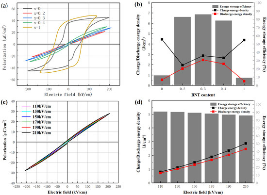
Figure 3.
(a) The hysteresis loops and (b) corresponding energy storage performance of the M–NN–xBNT composites; (c) the hysteresis loops corresponding to x = 0.3 and (d) corresponding energy storage performance under various electric fields.
The temperature dependence of energy storage performance is an important characteristic for evaluating the comprehensive performance of energy storage materials. Figure 4a describes the hysteresis loops at different temperatures. To prevent sample breakdown during temperature changes, an appropriate and reasonable testing electric field of 160 kV/cm was chosen. As observed, with the increase in ambient temperature from 30 °C to 100 °C, the ŋ slowly decreases. It is worth noting that within the temperature range of 30–80 °C, the energy storage density fluctuates by less than 10%, and the energy storage efficiency consistently remains above 80%. However, once the temperature surpasses 80 °C, the Wc of the composite ceramics exhibits a swift upward trend, leading to a swift decline in the value of ŋ.
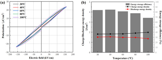
Figure 4.
Temperature stability of (a) the hysteresis loops and (b) corresponding energy storage performance.
The capacitance discharge test is another crucial method for evaluating the comprehensive application performance of energy storage ceramics, alongside the hysteresis loop test. During the application process, the load impedance value always remains at a low level; thus, the underdamped oscillation curves were tested, as illustrated in Figure 5a. The image demonstrates that the released current diminishes to approaching zero in a consistent manner after a few oscillation cycles. In addition, the initial peak current shows a consistent trend with the external electric field. The relevant charge and discharge characteristic parameters, including maximum current (Imax), power density (Pd = EImax/2S) and current density (j = Imax/S), are shown in Figure 6, with S representing the electrode area of the specimen. Notably, when a 100 kV/cm external electric field is applied, the sample achieves a maximum current of 34 A, with j and Pd attaining their respective peak values of 361 A/cm2 and 18 MW/cm3. In light of these outstanding discharging capabilities, the potential of M-NN-0.3BNT ceramics in the pulse power field is demonstrated.
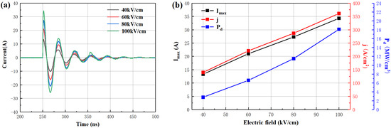
Figure 5.
(a) Underdamped discharge waveforms and (b) Imax, j and Pd for Mn-NN-0.3BNT samples under various electric fields.
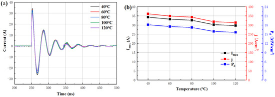
Figure 6.
Temperature dependence of (a) underdamped discharge waveforms and (b) Imax, j and Pd for Mn-NN-0.3BNT ceramics under 100 kV/cm.
The temperature dependence of undamped discharge is displayed in Figure 6. The images reveal that within the 40–120 °C range, there is a slight decrease in Imax, j, and Pd values as the ambient temperature rises, while the variation rate remains below 10%. The degradation of discharging performance can be attributed to the reduction in capacitance caused by the decrease in dielectric constant when exposed to high-temperature environments.
4. Conclusions
In this paper, 0.02xMnO2−(1−x)NaNbO3−xBi0.5Na0.5TiO3 composites were fabricated by the solid-state sintering method. At x = 0.3, the composites exhibit optimal compactness, with a corresponding maximum Eb valued at 210 kV/cm. Meanwhile, all components exhibit excellent solid solubility. Comprehensive analysis reveals that the M-NN-0.3BNT ceramic boasts an optimal Wd of 2.464 J/cm3, and attains an impressive ŋ of 85.8%. Furthermore, the M-NN-0.3BNT ceramic demonstrates considerable Pd (18 MW/cm3), substantial j (361 A/cm2), and consistent discharging performance with fluctuation less than 10% in the temperature range of 30–80 °C, all of which suggest promising application prospects in the pulse power field.
Author Contributions
Conceptualization, Y.Z.; Methodology and Investigation, L.Y. and M.Z.; Data Curation, H.L. and E.W.; Writing—Draft Presentation, J.G. and L.Z.; Writing—Review and Editing, J.G. and L.Z.; Funding Acquisition, Y.Z. All authors have read and agreed to the published version of the manuscript.
Funding
This work was supported by the Project of Henan Province Science and Technology (232102221003, 232102210183), the Special Project of Zhengzhou Basic Research and Application Basic Research (ZZSZX202435, ZZSZX202106), the Postgraduate Education Reform and Quality Improvement Project of Henan Province (YJS2023JD67).
Institutional Review Board Statement
Not applicable.
Informed Consent Statement
Not applicable.
Data Availability Statement
Data is contained within the article.
Conflicts of Interest
The authors declare no conflicts of interest.
References
- Taghaddos, E.; Charalambous, H.; Tsakalakos, T. Electromechanical properties of flash sintered BNT-based piezoelectric ceramic. J. Eur. Ceram. Soc. 2019, 39, 2882–2888. [Google Scholar] [CrossRef]
- Wang, Q.; Wang, T.; Zhang, L.; Liu, Z.; Guo, K.; Lu, J.; Xie, B. High energy-storage performance of lead-free Ba0.4Sr0.6TiO3–Sr0.7Bi0.2TiO3 relaxor-ferroelectric ceramics with ultrafine grain size. Ceram. Int. 2022, 48, 2068–2074. [Google Scholar] [CrossRef]
- Yuan, X.; Zhang, Y.; Gong, L.; Li, B.; Zhang, L. High energy storage performance of Na(Nb0.95Ta0.05)O3/Na0.5Bi0.5TiO3 lead-free ferroelectric ceramics. Ceram. Int. 2022, 48, 13244–13249. [Google Scholar] [CrossRef]
- Chauhan, A.; Patel, S.; Vaish, R.; Bowen, C. Anti-ferroelectric ceramics for high energy density capacitors. J. Mater. 2015, 8, 8009–8031. [Google Scholar] [CrossRef] [PubMed]
- Damjanovic, D.; Klein, N.; Jin, L.; Porokhonskyy, V. What can be expected from lead-free piezoelectric materials. J. Funct. Mater. Lett. 2010, 3, 5–13. [Google Scholar] [CrossRef]
- Shao, T.; Du, H.; Ma, H.; Qu, S.; Wang, J.; Wang, J.; Wei, X.; Xu, Z. Potassium-sodium niobate based lead-free ceramics: Novel electrical energy storage materials. J. Mater. Chem. A 2017, 5, 554–563. [Google Scholar] [CrossRef]
- Correia, T.; Stewart, M.; Ellmore, A.; Albertsen, K. Lead-free ceramics with high energy density and reduced losses for high temperature applications. J. Adv. Eng. Mater. 2017, 19, 1700019. [Google Scholar] [CrossRef]
- Wei, T.; Liu, K.; Fan, P.; Lu, D.; Ye, B.; Zhou, C.; Yang, H.; Tan, H.; Salamon, D. Novel NaNbO3-Sr0.7Bi0.2TiO3 lead-free dielectric ceramics with excellent energy storage properties. J. Ceram. Int. 2021, 47, 3713–3719. [Google Scholar] [CrossRef]
- Zhao, P.; Tang, B.; Si, F.; Yang, C.; Li, H.; Zhang, S. Novel Ca doped Sr0.7 Bi0.2TiO3 lead-free relaxor ferroelectrics with high energy density and efficiency. J. Eur. Ceram. Soc. 2020, 40, 1938–1946. [Google Scholar] [CrossRef]
- Tian, Y.; Jin, L.; Zhang, H. High energy density in silver niobate ceramics. J. Mater. Chem. A 2016, 4, 17279–17287. [Google Scholar] [CrossRef]
- Luo, N.; Han, K.; Zhuo, F. Design for high energy storage density and temperature-insensitive lead-free antiferroelectric ceramics. J. Mater. Chem. A 2019, 7, 4999–5008. [Google Scholar] [CrossRef]
- Zhou, M.; Liang, R.; Zhou, Z.; Yan, S.; Dong, X. Novel sodium niobate-based lead-free ceramics as new environment-friendly energy storage materials with high energy density, high power density, and excellent stability. J. ACS Sustain. Chem. Eng. 2018, 6, 12755–12765. [Google Scholar] [CrossRef]
- Qi, H.; Zuo, R.; Xie, A.; Tian, A.; Fu, J.; Zhang, Y.; Zhang, S. Ultrahigh energy-storage density in NaNbO3-based lead-free relaxor antiferroelectric ceramics with nanoscale domains. J. Adv. Funct. Mater. 2019, 29, 1903877. [Google Scholar] [CrossRef]
- Zhou, M.; Liang, R.; Zhou, Z.; Dong, X. Superior energy storage properties and excellent stability of novel NaNbO3-based lead-free ceramics with A-site vacancy obtained via a Bi2O3 substitution strategy. J. Mater. Chem. 2018, 6, 17896–17904. [Google Scholar] [CrossRef]
- Jin, L.; Li, F.; Green, D. Decoding the fingerprint of ferroelectric loops: Comprehension of the material properties and structures. J. Am. Ceram. Soc. 2014, 97, 1–27. [Google Scholar] [CrossRef]
- Zhao, L.; Liu, Q.; Zhang, S. Lead-free AgNbO3 anti-ferroelectric ceramics with an enhanced energy storage performance using MnO2 modification. J. Mater. Chem. A 2016, 4, 8380–8384. [Google Scholar] [CrossRef]
- Shen, Z.; Wang, X.; Luo, B.; Li, L. BaTiO3-BiYbO3 perovskite materials for energy storage applications. J. Mater. Chem. A 2015, 3, 18146–18153. [Google Scholar] [CrossRef]
- Ye, J.; Wang, G.; Zhou, M. Excellent comprehensive energy storage properties of novel lead-free NaNbO3-based ceramics for dielectric capacitor applications. J. Mater. Chem. A 2019, 7, 5639–5645. [Google Scholar] [CrossRef]
- Yang, Z.; Du, H.; Xu, Z. A new family of sodium niobate-based dielectrics for electrical energy storage applications. J. Eur. Ceram. Soc. 2019, 39, 2899–2907. [Google Scholar] [CrossRef]
- Fan, Y.; Zhou, Z.; Liang, R. Designing novel lead-free NaNbO3-based ceramic with superior comprehensive energy storage and discharge properties for dielectric capacitor applications via relaxor strategy. J. Eur. Ceram. Soc. 2019, 39, 4770–4777. [Google Scholar] [CrossRef]
- Guo, B.; Yan, Y.; Tang, M.; Wang, Z.; Li, Y.; Zhang, L.; Zhang, H.; Jin, L.; Liu, G. Energy storage performance of Na0.5Bi0.5TiO3 based lead-free ferroelectric ceramics prepared via non-uniform phase structure modification and rolling process. J. Chem. Eng. 2021, 420, 130475. [Google Scholar] [CrossRef]
- Ng, Y.; Alexander, S. Structural studies of manganese stabilized lead zirconate titanate. J. Ferroelectr. 1983, 51, 81–86. [Google Scholar] [CrossRef]
- Yan, Y.; Cho, K.; Priya, S. Identification and effect of secondary phase in MnO2-doped 0.8Pb(Zr0.52Ti0.48)O3-0.2Pb(Zn1/3Nb2/3)O3 piezoelectric ceramics. J. Am. Ceram. Soc. 2011, 94, 3953–3959. [Google Scholar] [CrossRef]
Disclaimer/Publisher’s Note: The statements, opinions and data contained in all publications are solely those of the individual author(s) and contributor(s) and not of MDPI and/or the editor(s). MDPI and/or the editor(s) disclaim responsibility for any injury to people or property resulting from any ideas, methods, instructions or products referred to in the content. |
© 2024 by the authors. Licensee MDPI, Basel, Switzerland. This article is an open access article distributed under the terms and conditions of the Creative Commons Attribution (CC BY) license (https://creativecommons.org/licenses/by/4.0/).