1. Introduction
Piezoelectric pumps, as a new type of fluid actuator, can achieve the precise control of fluid flow from microscopic to macroscopic scales. They are widely used in medical drug delivery systems [
1], fuel delivery [
2], cooling systems for electronic chips [
3], precise solution metering systems [
4], and other fields. These pumps possess advantages such as a simple structure, low energy consumption, and strong anti-interference capabilities.
In 1978, W.J. Spence et al. [
5] first proposed a design for a miniature piezoelectric pump and an electronic release valve for insulin delivery, opening up a new research field focusing on piezoelectric pumps. Since then, scholars worldwide have continued to explore the theoretical principles and practical applications of piezoelectric pumps in various fields, classifying them based on specific characteristics. One such classification is according to the multi-chamber structure of the piezoelectric pumps.
These multi-chamber piezoelectric pumps are primarily divided into three types: multi-chamber series [
6], multi-chamber parallel [
7], and multi-chamber series–parallel [
8] configurations. The series structure can effectively enhance the output pressure of the piezoelectric pump. Jiajian Ji et al. [
9] developed a novel three-chamber series piezoelectric pump utilizing a wedge valve. Compared to the traditional series piezoelectric pump, its main feature lies in the flexible support structure inside the chambers, which allows for adjustable chamber height. The experimental results show that the maximum output flow rate and output pressure of this design reached 828.4 mL/min and 20.1 kPa, respectively, demonstrating significant improvements over the conventional design.
The parallel structure can improve the output flow rate of the piezoelectric pump. Guo Li et al. [
10] proposed a design for a valveless piezoelectric pump with a single vibrator and dual chambers in parallel, fabricated using MEMS technology. They also performed optimization simulations on the pump structure using ANASYS software. The experimental results showed that the output flow rate of the optimized dual-chamber parallel piezoelectric pump is 1.3 times that of the single-chamber piezoelectric pump. The piezoelectric pump with a multi-chamber series–parallel structure combines the advantages of both series and parallel configurations, improving both output pressure and flow rate. Abhijeet Vante et al. [
11] conducted liquid delivery experiments on multi-chamber piezoelectric pumps with different structures. The results showed that the series–parallel configuration exhibited the advantage of series type in increasing output flow and parallel type in enhancing output pressure during operation. However, this design did not integrate the multi-chamber piezoelectric pump. It only changed the connection method of each single-chamber piezoelectric pump using hoses, resulting in a relatively large device size.
Although the multi-chamber series structure piezoelectric pump can increase output pressure, the improvement in output flow rate is limited. On the other hand, the multi-chamber parallel structure can significantly enhance the output flow rate, but the increase in output pressure is limited. Combining the advantages and disadvantages of both multi-chamber series and parallel structures, this study proposes a stacked four-chamber series–parallel piezoelectric pump, which not only enhances the output flow rate but also improves the output pressure. The stacked design also makes the pump body more compact. By analyzing the working principles of the multi-chamber series–parallel piezoelectric pump, three prototypes—series, parallel, and series–parallel—were developed. Comparative experiments on liquid media were conducted to explore the impact of the series–parallel structure on the output performance of the piezoelectric pump. This research provides a reference for the integration and miniaturization of precision fluid delivery systems using piezoelectric pumps. It also offers technical insights for applications requiring excellent output performance, precise flow control, and a simple and compact structure, such as precise drug delivery, accurate solution mixing, and electronic chip cooling.
2. Structural Design and Working Principle
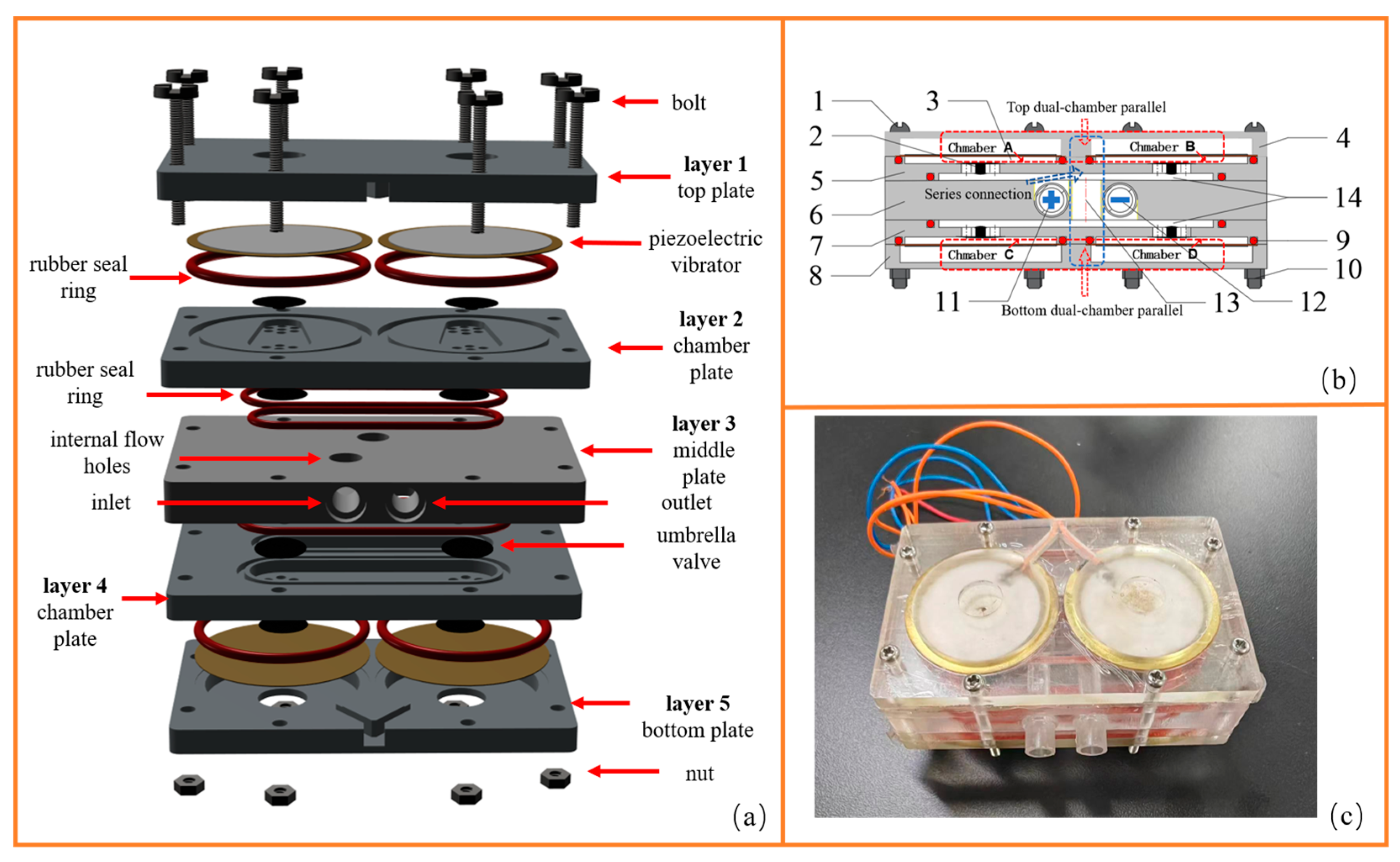
The four-chamber series–parallel piezoelectric pump in this study adopts a five-layer stacked structure, symmetrically arranged left and right, as shown in
Figure 1. Layers 1 and 5 are piezoelectric vibrator cover plates, layers 2 and 4 are chamber plates, and layer 3 is the middle body. The piezoelectric vibrator is secured between the cover plate and the chamber plate and sealed with a rubber ring. The pump chamber, flow channels, and umbrella-shaped check valves at the chamber’s inlet and outlet are all located on the chamber plates. The inlet check valve is installed inside the chamber, while the outlet check valve is installed inside the outlet groove. The inlet and outlet holes are located on the side of the middle layer, and circular holes are machined in the middle layer to connect the outlet groove of the upper chamber plate with the inlet groove of the lower chamber plate. Each chamber is equipped with an inlet umbrella valve, forming a four-valve structure. To enhance the cut-off performance of the piezoelectric pump during operation, outlet check valves can be installed inside the chambers, resulting in six-valve or eight-valve structures. Rubber seals are placed at the connection points between the piezoelectric vibrators, the inlet and outlet grooves of the chamber plates, and the middle body to ensure the airtightness of the piezoelectric pump. In the four chambers shown in
Figure 1b, chamber A and chamber B are connected in parallel to form a top dual-chamber parallel structure, and chamber C and chamber D are also connected in parallel to form a bottom dual-chamber parallel structure. The top and bottom dual-chamber parallel structure is connected in series through the through-hole in the middle layer to form a four-chamber series–parallel structure, where + indicates that the water flows in from the water inlet, and – indicates that it flows out from the water outlet hole. The relevant parameters of the fabricated four-chamber series–parallel piezoelectric pump prototype are shown in
Table 1.
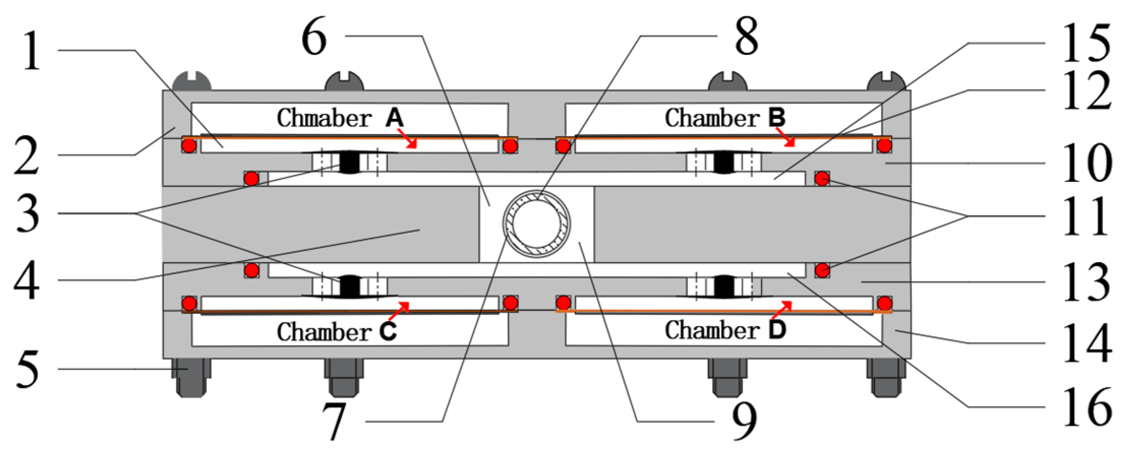
Figure 2 illustrates the structure of the four-chamber parallel piezoelectric pump designed by Xiaofeng Sun et al. [
12], which uses a five-layers stacked structure. It is completely symmetrical on all sides—top, bottom, left, and right. The structure mainly includes two cover plates for securing the piezoelectric vibrators, chamber plates with chamber and inlet/outlet flow channels, and a middle separator.
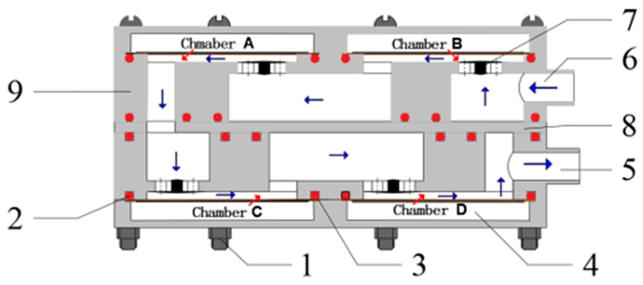
Figure 3 shows the structure of the four-chamber series piezoelectric pump designed by Xiaofeng Sun et al. [
13], also using a five-layer stacked structure. It adopts two piezoelectric vibrator cover plates, two symmetrical chamber plates, and a middle separator with through-holes. The through-holes in the middle separator connect the upper and lower double-chamber series sections. The arrows in
Figure 3 indicate the direction of fluid flow during the operation of the four-chamber series piezoelectric pump.
3. Theoretical Output Performance Calculation of the Piezoelectric Pump
In this design, both the upper and lower chambers of the four-chamber series–parallel piezoelectric pump adopt a parallel design, and they are connected in series through the flow holes in the middle body. In terms of output performance, this configuration is equivalent to connecting two double-chamber parallel piezoelectric pumps in series. As noted in reference [
14], assuming that the piezoelectric ceramic in the piezoelectric pump is rigidly connected to the bonded metal substrate without any relative displacement, the radial deformation at the center point of the piezoelectric transducer inside a single chamber under the excitation of an applied driving voltage is as follows:
where
is the diameter of the piezoelectric vibrator;
is the thickness of the piezoelectric vibrator;
is the piezoelectric constant of the vibrator; and
is the driving voltage.
The shape change in the chamber caused by the vibration of the piezoelectric vibrator within a single driving signal cycle is similar to the spherical cap shape shown in
Figure 4, and can be calculated as follows:
The output flow rate of a typical single-chamber piezoelectric pump can be calculated as follows:
where
represents the operating frequency of the piezoelectric vibrator; and
represents the efficiency of the umbrella-type check valve.
Assuming that the operating performance of each piezoelectric oscillator is exactly the same, the operating efficiency of the umbrella shutoff valve inside each cavity is exactly the same, as well as ignoring the machining errors due to the machining process, etc., the theoretical output flow rate for each parallel section would be as follows:
As indicated in the literature [
15], the output pressure of a parallel-structured piezoelectric pump is equal to the maximum output pressure of the individual chambers when working separately, while the output pressure at the outlet of a series-structured piezoelectric pump is the sum of the output pressures of the individual chambers working in series. The total output pressure of the four-chamber series–parallel piezoelectric pump is equal to the sum of the output pressures of the upper and lower parallel sections working independently. The theoretical output pressure is as follows:
where
and
is the output pressures of the top and bottom parallel sections working independently.
From the Bernoulli equation, the relationship between the output pressure and the output flow rate can be expressed as follows:
where
is the flow coefficient,
is the cross-sectional flow area of the piezoelectric pump’s pipeline, and
is the fluid density.
The piezoelectric pump designed in this paper did not leak during the pumping liquid experiment. If the energy loss caused by the liquid leakage is not considered, and the local pressure loss and the pressure loss along the flow of the liquid in the piezoelectric pump are considered, the above equation is corrected as follows:
where
α (0 <
α < 1) is the pressure correction factor, determined by experimental results.
If the output capacities of the upper and lower double-chamber parallel sections are identical, the equation simplifies to the following:
That is, the output flow rate of the four-chamber series–parallel piezoelectric pump is times the output flow rate when the dual chambers of either the top or bottom layer operate in parallel independently.
The output flow rates of the four-chamber series structure and the four-chamber parallel structure are as follows:
where
n is the number of chambers.
4. Prototype Manufacturing and Experimental Results Analysis
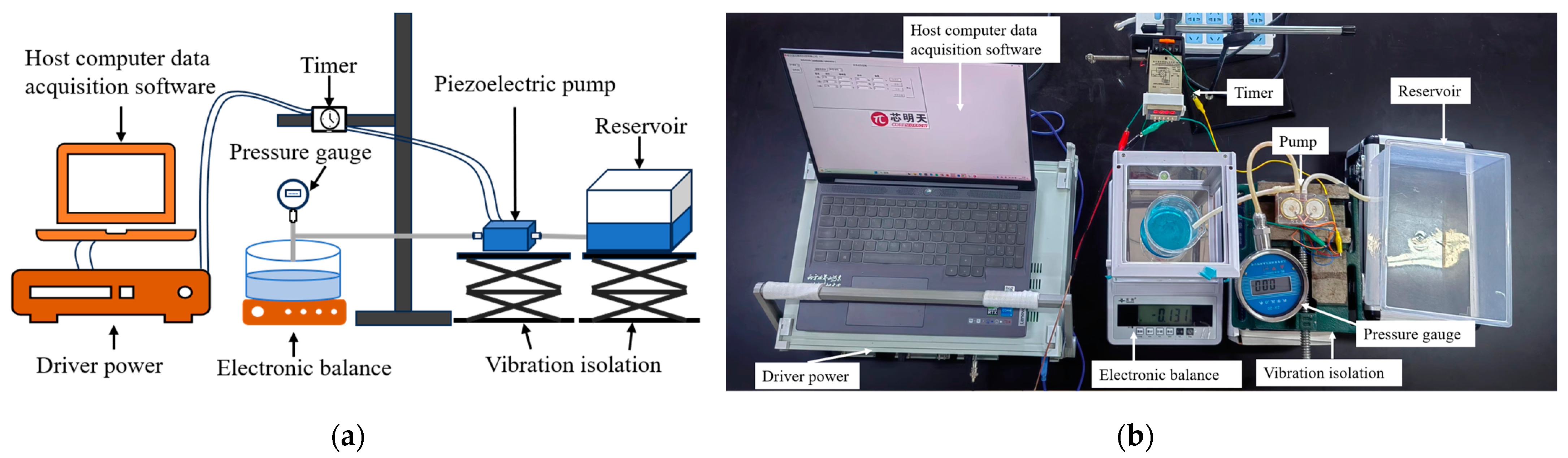
The piezoelectric vibrators of the three different structures of the four-chamber piezoelectric pumps all used a beryllium bronze substrate with a diameter of 35 mm and a piezoelectric single crystal with a diameter of 29 mm. Both the substrate and piezoelectric ceramic thickness were set to 0.2 mm. The piezoelectric ceramic material used is PZT-5A. The primary equipment used for the liquid delivery performance tests of the four-chamber series–parallel piezoelectric pump includes a piezoelectric ceramic driver power, a timer, a digital pressure gauge with a minimum measurement of 0.01 kPa, a beaker, and a precision balance. The experimental platform for testing the liquid delivery performance of the four-chamber series–parallel piezoelectric pump is shown in
Figure 5.
Under the drive of alternating voltage, the working states of the piezoelectric vibrators in a multi-chamber piezoelectric pump are different at the same time, leading to varying output performances of the pump. When the volumes of the chambers increase or decrease simultaneously, it is referred to as synchronous operation; conversely, it is called asynchronous operation. According to references [
16,
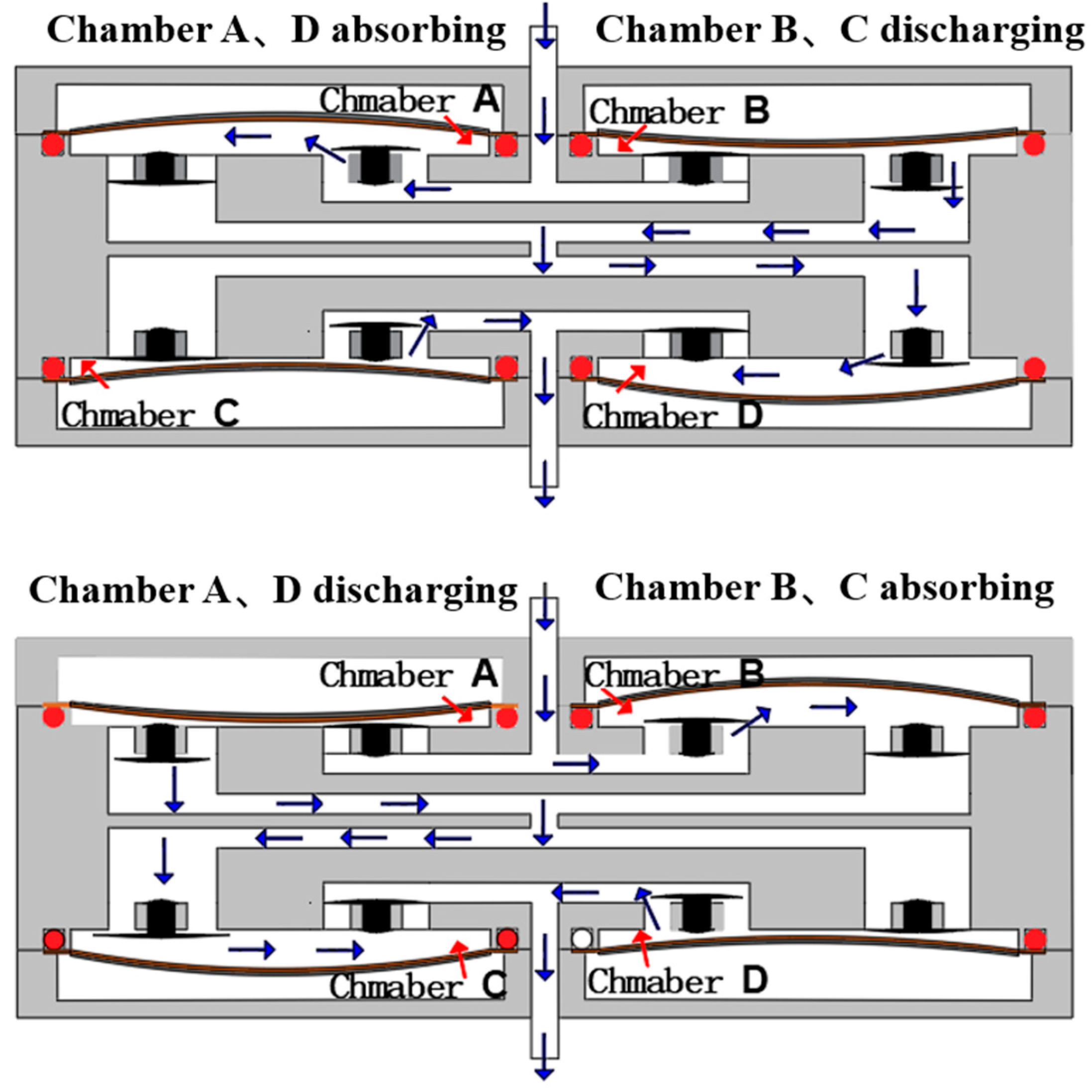
17], for both series and parallel structured multi-chamber piezoelectric pumps, the pump’s output performance is optimal when the piezoelectric vibrator operates asynchronously. This means that while one chamber is in the water absorb phase, another chamber is in the water discharge phase. In the experiment, the driving signals of the piezoelectric transducers in the four chambers of the three different piezoelectric pump structures are as follows: the phase difference between the driving signals of the piezoelectric vibrator in chamber A and chamber D is 0°, and the phase difference between the driving signals of the piezoelectric vibrator in chamber B and chamber C is 0°. Additionally, the phase difference between the driving signals of the piezoelectric vibrator in chamber A and chamber B is 180°. During operation, the working state of the chambers is shown as follows: chambers A and D, and chambers B and C are in synchronous operation, while chambers A and C are in asynchronous operation. That is, when chambers A and D are in the water absorb or discharge phase, chambers B and C are in the discharge or water absorb phase. In the experiment, water was used as the liquid medium, the ambient temperature was 20 °C, and the driving voltage was 110 V.
Figure 6 is a schematic diagram of the working process of the four-chamber series–parallel piezoelectric pump, which is mainly divided into two stages: Stage 1, wit chambers A and D absorbing water while chambers B and C discharge water, and Stage 2, where chambers A and D discharge water while chambers B and C absorb water. For better visualization, the internal flow channels of the chambers have been flattened. The red arrow in
Figure 6 represents the chamber and the blue arrow represents the direction of liquid flow.
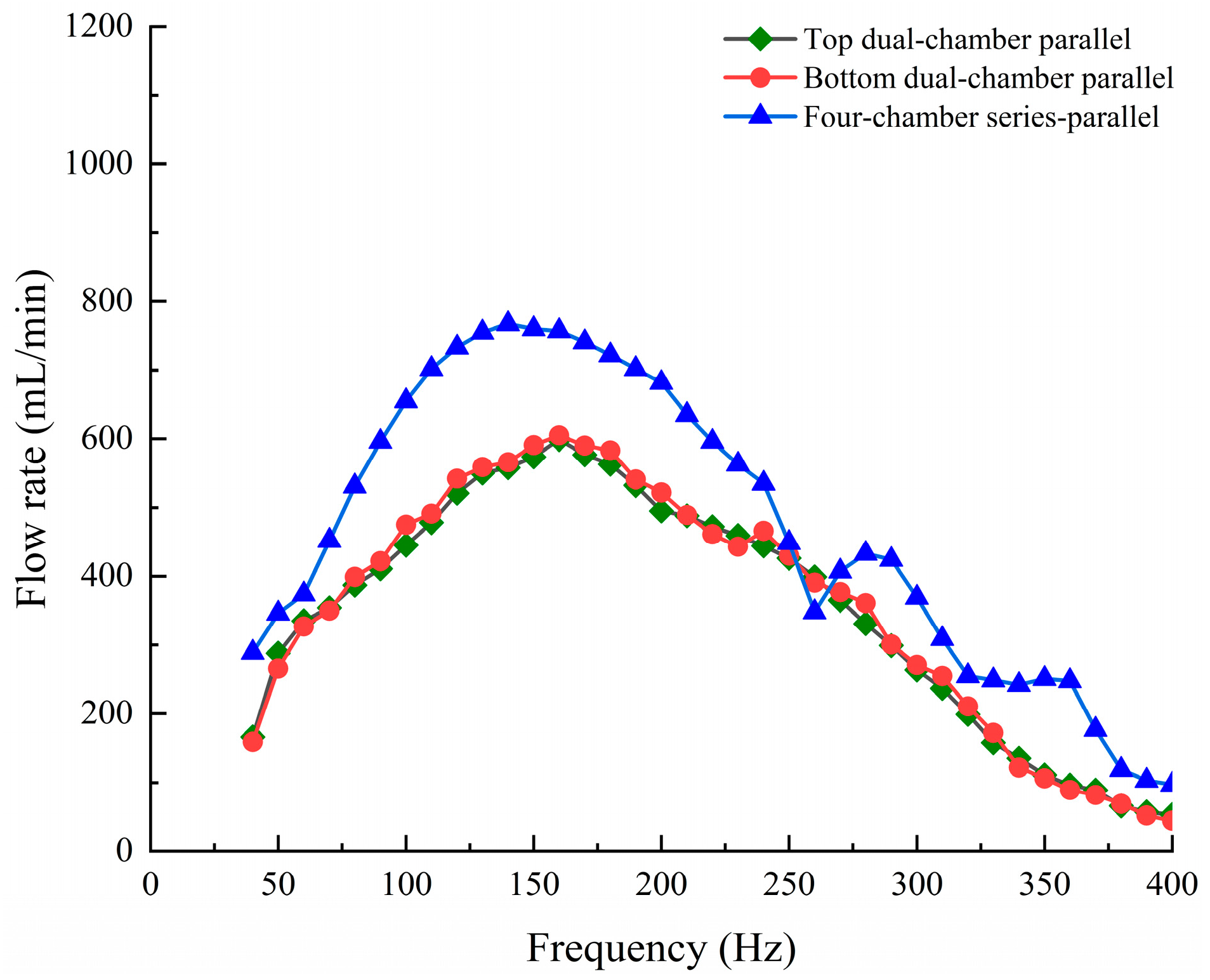
The four-chamber series–parallel structure consists of two dual-chamber parallel sections connected in series. Driving tests were conducted separately on the A and B piezoelectric chamber, as well as on the C and D piezoelectric chamber, to measure the output performance of the upper and lower dual-chamber parallel sections during independent operation. The test result curves are shown in
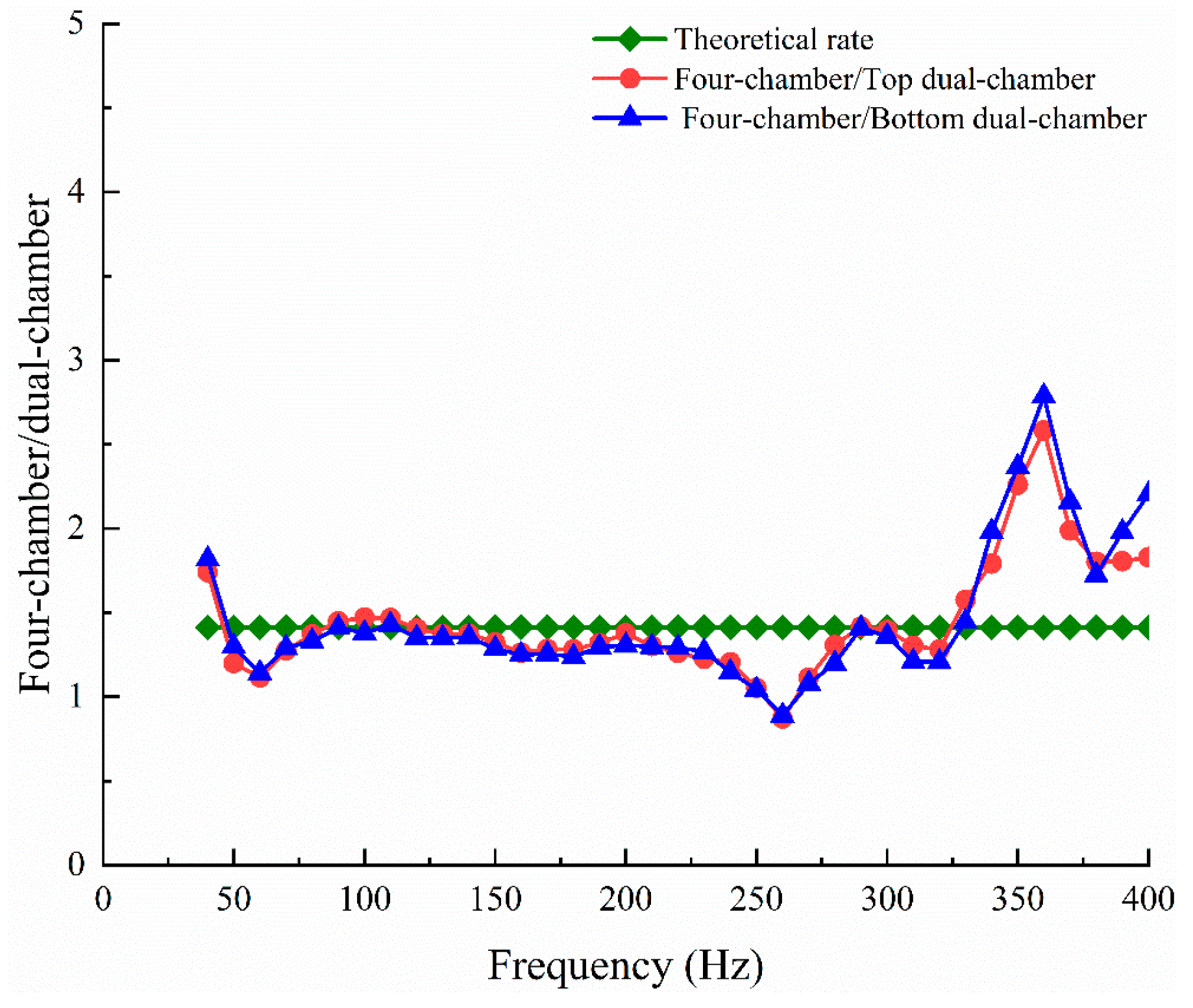
Figure 7. From the curve variations, it can be observed that the output flow rate curves of the upper and lower parallel pumps are highly consistent. According to Equation (7), the theoretical flow rate ratio between the overall output of the four-chamber series–parallel piezoelectric pump and the output of the upper and lower parallel sections should be
:1. However, the actual calculations show that the flow rate ratio between the parallel structure and the four-chamber series–parallel structure is more dispersed, as shown in
Figure 8. After calculating the results one by one, it was found that the flow rate ratio between the output when all four chambers work together and the output when the top and bottom parallel chambers work independently ranges from 1.25 to 2, with a concentration around 1.4, which is consistent with Equation (7).
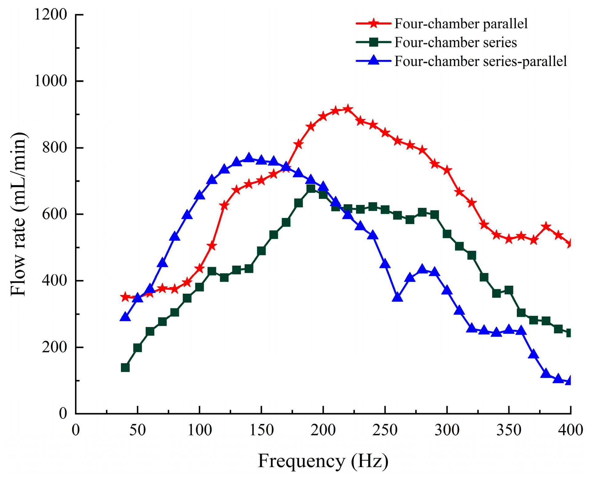
Figure 9 shows the curve of the output flow rate of the four-chamber piezoelectric pump with different structures transporting liquid water as a function of frequency. It can be seen that the optimal operating frequency range varies among different pump structures. The four-chamber series–parallel piezoelectric pump exhibits strong liquid transport capability at low frequencies, with a maximum output flow rate of 767 mL/min and an optimal operating frequency of 140 Hz. The four-chamber series–parallel structure has a lower optimal frequency compared to the other two structures. However, as the frequency increases, its output capacity decreases significantly. The critical threshold is 240 Hz, beyond which the output flow rate of the four-chamber series–parallel structure drops sharply. In the four-chamber parallel structure, after water is discharged from each chamber, it flows through the internal channel and exits through the same outlet of the piezoelectric pump. When the four parallel chambers operate asynchronously, two chambers are always in the discharge phase simultaneously, causing the discharged liquids to collide at the outlet, resulting in energy loss. Although in the series–parallel structure two chambers are also in the discharge phase at the same time, only the chambers in the lower parallel section discharge water through the outlet holes, resulting in less energy loss. The four-chamber parallel structure, on the other hand, significantly increases the output flow rate due to the increased number of parallel chambers, effectively compensating for the flow reduction caused by energy loss at higher frequency ranges.
Figure 10 shows the output pressure variation curves for different structures of piezoelectric pumps while delivering water. It is evident from the curve that the four-chamber series piezoelectric pump has the best output pressure, with the curve remaining relatively smooth in both the low- and high-frequency ranges. The four-chamber series–parallel structure shows a significant improvement in output pressure compared to the four-chamber parallel structure, with a maximum increase of 62.1%. However, as the frequency increases, the output pressure of the four-chamber series–parallel structure fluctuates more significantly, resulting in less stability compared to the four-chamber series and four-chamber parallel structures.
Table 2 shows the comparison of the output performance of the four-chamber series–parallel piezoelectric pump proposed in this paper with previous piezoelectric pump works.
From the flow output curves, it can be observed that under low-frequency driving, the output flow rate of the piezoelectric pump increases linearly with the rise in frequency. However, under high-frequency driving, the output flow rate experiences a sharp decrease. This behavior is attributed to the fact that the four-chamber series–parallel piezoelectric pump proposed in this paper is a type of valve pump that employs umbrella-shaped check valves. This design enhances the cut-off performance of the piezoelectric pump during operation, but at the same time, the umbrella valves experience phase lag during high-frequency operation, causing a delay in the opening and closing of the valves relative to the movement of the piezoelectric vibrators. There is a gap between the check valves and the valve seats, which further leads to a reduction in output flow rate.
Under low-frequency driving, the series–parallel structure benefits from the parallel configuration of the upper and lower layers, where the two parallel chamber piezoelectric vibrators are driven asynchronously. During operation, the volumes of the two parallel chambers are always in an alternating state of change. Compared to the four-chamber series structure, this effectively increases the water pumping time of the piezoelectric pump within one working cycle, thereby enhancing the output flow rate. This aligns with the earlier mentioned theory that parallel configurations improve the output flow rate of piezoelectric pumps.
From the output pressure curves, it can be observed that the output pressure of the four-chamber series–parallel piezoelectric pump shows a significant improvement compared to the parallel structure. Although the parallel structure can enhance the output flow rate, the output pressure is equal to that of the maximum output from a single chamber during its working cycle, as the parallel chambers are in an alternating state of change. The four-chamber series–parallel structure connects two dual-chamber parallel configurations in series, where the output pressure of the series-structured piezoelectric pump is the sum of the output pressures when each chamber operates individually. Thus, the output pressure of the four-chamber series–parallel piezoelectric pump is equivalent to the sum of the output pressures of the upper and lower parallel chambers, which aligns with the theory that series configurations increase the output pressure of piezoelectric pumps.
The efficiency of the piezoelectric pump is calculated by Equation (10):
where
is the output pressure of the piezoelectric pump;
is the output flow rate of the piezoelectric pump;
is the operating voltage of the piezoelectric pump; and
is the operating current of the piezoelectric pump.
The efficiency of the piezoelectric pump was calculated as λ = 73% when the operating frequency was selected as 110 Hz, = 34.4 kPa, = 407 mL/min, = 110 V, and = 0.7 mA.
Based on the structure and operating conditions of the piezoelectric pump, its service life is equivalent to the fatigue life of the piezoelectric transducer. Using the method outlined in the author’s literature [
18], the fatigue life of the PZT-5 piezoelectric transducer used in the piezoelectric pump in this study was calculated through the fatigue damage accumulation hypothesis, resulting in approximately 4400 h, which corresponds to the service life of the piezoelectric pump. A safety factor of 1.25 was selected. Under the environmental conditions of a room temperature between 18 and 25 °C and an air humidity not exceeding 60%, and with excitation voltages below 120 V and frequencies of 0–400 Hz, the fatigue life (mechanical fatigue and electrical fatigue) of the PZT-5 piezoelectric transducer (origin: Shenzhen, China) used in the piezoelectric pump was experimentally measured. After removing outliers, the results showed a fatigue life of 3600 to 4900 h. However, for ceramics of the same material grade but from different origins, the service life can vary significantly due to slight differences in manufacturing processes, ranging from 930 h to 4900 h. In particular, when air humidity exceeds 86%, the fatigue life of the piezoelectric transducer significantly decreases to below 1000 h. This is caused by moisture in the air adhering to the surface of the ceramics, leading to the formation of cracks until failure occurs.
During the experiment, we simultaneously recorded the operating noise of the four-chamber series–parallel piezoelectric pump, which ranged from 60.1 dB to 95.6 dB, and the noise magnitude showed an increasing trend with increasing frequency. The piezoelectric pump drive voltage is 110 V, the drive waveform is sinusoidal, and the frequency range is 40–400 Hz.
5. Conclusions
This paper presents a four-chamber series–parallel piezoelectric pump with a stacked structure. Prototypes were fabricated, and liquid delivery tests were conducted on three different structures: series, parallel, and series–parallel multi-chamber piezoelectric pumps. The following conclusions were drawn:
(1) The four-chamber series–parallel piezoelectric pump exhibits strong liquid delivery performance in the low-frequency driving. Under a driving frequency of 140 Hz, the maximum output flow rate can reach 767 mL/min, which is an increase of 75.5% compared to the four-chamber series piezoelectric pump. At a driving frequency of 200 Hz, the output pressure can reach 42.3 kPa, which is an increase of 62.1% compared to the output pressure of the four-chamber parallel structure.
(2) The multi-chamber series–parallel structure can enhance the output performance of the piezoelectric pump by leveraging the advantages of increased output pressure from the series structure and improved output flow rate from the parallel structure. Its maximum output flow rate is increased by 13.3% compared to the four-chamber series piezoelectric pump, and its maximum output pressure is increased by 43.4% compared to the four-chamber parallel piezoelectric pump.
(3) The comprehensive output performance of the four-chamber series–parallel piezoelectric pump is good under low-frequency driving, with a boundary at 240 Hz. Below this frequency, all output performances vary relatively smoothly with changes in frequency, making it suitable for efficient liquid delivery under low-frequency conditions below 240 Hz.
(4) The fatigue life of the PZT-5 piezoelectric actuator used in the four-chamber series–parallel piezoelectric pump in this paper was measured; it can reach between 3600 and 4900 h. The efficiency of piezoelectric pump was calculated as λ = 73% when the operating frequency was selected as 110 Hz, and its operating noise range is from 60.1 dB to 95.6 dB.


