Abstract
To investigate the effect of the content of yttrium nitrate on the microstructure and properties of micro-arc oxidation coatings on a ZK61M magnesium alloy, this study successfully prepared a ZrO2-Y2O3-containing composite ceramic coating on a ZK61M magnesium alloy by using micro-arc oxidation (MAO) technology, adding different amounts of yttrium nitrate (0 g/L, 0.15 g/L, 0.45 g/L, and 0.75 g/L) to a zirconate electrolyte with the main components of 6 g/L of (NH4)2ZrF6, 4 g/L of NaH2PO4, 1 g/L of NaF, and a pH value of 7.5–8.0. The microstructure, phase composition, corrosion resistance, and friction coefficient of the coating were investigated using a scanning electron microscope, an energy spectrometer, an X-ray diffractometer, a photoelectron spectrometer, an electrochemical tester, and a friction and wear tester, respectively. The results showed that the composite ceramic coating was composed of c-ZrO2, t-ZrO2, m-ZrO2, MgO, Y2O3, and MgF2. Among the MAO coatings prepared in this experiment, it was when the concentration of the Y(NO3)3 was 0.75 g/L that the coating exhibited the best corrosion resistance and wear resistance. The corrosion current density (Icorr) was 1.415 × 10⁻⁸ A·cm−2, which was four orders of magnitude lower than that of the substrate. The friction coefficient and wear volume of the coating were reduced by 30.77% and 96.55% compared to the substrate, respectively.
1. Introduction
Magnesium alloy is a low-density structural material with a density of only 1.8 g/cm3. It has high specific strength, good heat dissipation, strong shock absorption, and high impact strength, as well as an excellent electromagnetic shielding performance. It is widely employed in the manufacture of engine casings, radar shells, notebook shells, satellite brackets, wing skins for anti-aircraft missiles, and rudders. Furthermore, it has numerous applications in the fields of automotive and high-speed rail transportation [1,2,3,4]. However, the inferior chemical stability, corrosion resistance, and wear resistance of magnesium are significant limitations that must be addressed to enable its expanded use in industrial applications [5,6]. As a result, a current research focus for expanding the applications of magnesium alloys is improving the corrosion resistance of magnesium alloys through surface treatment.
Micro-arc Oxidation (MAO), also known as micro discharge oxidation, spark anodizing, or micro plasma oxidation, is an effective surface treatment technique, which can convert the surfaces of valve metals such as aluminum, magnesium, titanium, etc., into ceramic coatings. Recently, micro-arc oxidation has attracted more and more attention in the research of magnesium alloy surface protective coatings because of its low cost, the environmental protection process, and its ability to obtain a thick ceramic coating [7,8,9]. Due to its good chemical stability and corrosion resistance, zirconium dioxide can be introduced as an oxide into the micro-arc oxidation coating to improve the corrosion resistance of magnesium alloys [10,11]. The ZrO2-containing coating prepared using MAO on a Mg alloy in a zirconate electrolyte has gradually attracted the attention of researchers [12,13,14]. As reported, the formation of a ZrO2-containing coating on the surface of a magnesium alloy can enhance its corrosion resistance. Chen et al. [15] obtained a ZrO2-containing coating composed of MgO, Mg2SiO4, and ZrO2 using MAO on an AZ31 magnesium alloy in a K2ZrF6 electrolyte. The results of their study indicated that the composite coating significantly improves the corrosion resistance of the magnesium alloy. Gao et al. [16] fabricated a porous ZrO2 ceramic coating on the surface of an AZ31B magnesium alloy using magnetron sputtering and MAO. An electrochemical test showed the corrosion resistance of the AZ31B was improved in a simulated body fluid solution. Tang et al. [17] prepared a ZrO2-Mg2ZrO12-MgO composite MAO coating on an AZ91D magnesium alloy through the addition of ZrO2 nanoparticles to a phosphate solution containing 10 g/L of K2ZrF6. The findings demonstrated that adding the ZrO2 nanoparticles enhanced the thickness, compactness, and corrosion resistance of the coating.
In addition to the research on a ZrO2-containing MAO coating, researchers have also studied the corrosion resistance and wear resistance of a Y2O3-containing coating on the surface of a magnesium alloy using MAO. Chen et al. [18] investigated a micro-arc oxidation coating composed of Ca8MgY (PO4)7 and Y2O3 on a ZK60 magnesium alloy. The results showed that both the degradation resistance and the wear properties of the coating were improved. Han et al. [19] incorporated Y2O3 nanoparticles into the MAO coating of an AZ91 magnesium alloy, resulting in a significant reduction in the corrosion current density of approximately three orders of magnitude compared to that of the blank AZ91. Zhao et al. [20] conducted a study to evaluate the behavior of Y2O3/Nd2O3 particles in the MAO coating of an AZ91D magnesium alloy. The results showed that the corrosion resistance of the AZ91D magnesium alloy was significantly improved by the addition of the Y2O3 particles.
However, there are few studies that demonstrate the effects of Y2O3/ZrO2 on the corrosion resistance and wear property of the MAO coating of a magnesium alloy. Therefore, some yttrium nitrate was added into the electrolyte to fabricate a Y2O3/ZrO2-containing MAO coating on a ZK61M alloy in this work. The micro-structure, corrosion resistance, and wear property of the MAO coating were studied. The valuable exploration of this research creates the possibility of designing a high-performance MAO coating of Mg alloys.
2. Materials and Methods
2.1. Samples and Coating Preparation Procedures
In this study, the substrate for the MAO coating was a ZK61M magnesium alloy, consisting of Zn (5.40 wt.%), Zr (0.42 wt.%), Mn (0.02 wt.%), Si (<0.01 wt.%), Fe (<0.003 wt.%), Cu (<0.05 wt.%), Ni (<0.005 wt.%), and Mg (balance). The alloy was cut into a size of 15 × 15 × 5 mm prior to the aforementioned coating preparation. Prior to the MAO treatment, the alloy’s surface was prepped via grinding and polishing with SiC sandpaper grits ranging from 800 to 2000, followed by ethanol and deionized water ultrasonic cleaning, and dried thereafter.
2.2. Experiment Process
The MAO-300D micro-arc oxidation machine (at the Northwest Institute for Nonferrous Metal Research, Xi’an, China) was used in the MAO process and includes a power supply, an electrolytic cell, a stirrer, and a refrigerant. The base electrolyte components were 6 g/L of (NH4)2ZrF6, 4 g/L of NaH2PO4, 1 g/L of NaF, and NaOH. The NaOH was mainly used to adjust the pH value of the solution (7.5–8.0). Samples “Y1”, “Y2”, “Y3”, and “Y4” were developed in the base electrolyte with 0 g/L, 0.15 g/L, 0.45 g/L, and 0.75 g/L of Y(NO3)3, respectively. Following the results of previous research [9], the micro-arc oxidation process was carried out using a constant voltage mode. The operating voltage was 450 V; the operating frequency was 500 Hz; the duty cycle was 15%; and the preparation time was 15 min.
2.3. Characterization
The surface and cross-sectional morphologies of the coating were characterized via a scanning electron microscopy, VEGA II XMU (OXFORD, Oxford, UK). The distribution of elements on the surface and the cross-section of the coating was analyzed via an energy dispersive spectroscopy (EDS). A laser scanning confocal microscopy (using a Zeiss LSM 800 from Zeiss, Jena, Germany) was used to analyze the three-dimensional morphology and roughness of the coating. The phase composition of the coating was determined with a D/max 2200 PC X-ray diffractometer (RIGAKU, Tokyo, Japan) at 45 kV and 200 mA Cu Kα. The detected range was 20°–80°; the step size was 0.02°; and the scanning rate was 2°/min. An X-ray photoelectron spectroscopy (XPS, ESCALAB 250Xi, Thermo Fisher Scientific, Waltham, MA, USA) was used to analyze the chemical composition of the coating.
The electrochemical testing was conducted at room temperature using an electrochemical workstation Versa STAT 3F (AMETEK, Pennsylvania, PA, USA) in a 3.5 wt.% NaCl solution. In the electrochemical testing process, the saturated calomel electrode (SCE) was used as the reference electrode, the MAO-coated sample as the working electrode (1 cm2 exposed area), and the Pt grid as a counter electrode. The polarization curves were measured at a scanning rate of 2 mV/s and at a potential range of −0.5 V to 2.0 V.
The wear resistance and friction coefficient of the sample were tested with a friction and wear tester (MS-T3000, Lanzhou institute of chemical physics, Lanzhou, China) under a dry sliding condition at room temperature. A silicon nitride ball that was 5 mm in diameter was used for the friction test. The sample was rotated at a rate of 500 r/min and a load of 150 g for 20 min with a rotation radius of 3 mm. When the wear tests were completed, the cross-sectional geometry of the wear scars was analyzed by a profilometer (MFT-4000, Lanzhou institute of chemical physics, Lanzhou, China), and the wear volumes were calculated using the data of the geometric profile.
3. Results and Discussion
3.1. Surface Morphology of MAO Coatings
Figure 1 shows the SEM micrograph of the MAO coating formed with different concentrations of the Y(NO3)3. As observed from the figure, an increase in the concentration of the Y(NO3)3 resulted in a decreased micropore count and size on the coating surface, indicating low porosity. The addition of the Y(NO3)3 significantly decreased the number of cracks on the coating surface, demonstrating its effective suppression of the formation of cracks in the coating and a positive stabilizing impact. During the rapid solidification of molten oxide products in the strong discharge channel, coating cracks are mainly formed due to thermal stress [21]. Compared to Figure 1a, there was a slight decrease in pore size and a slight increase in the number of micropores on the coating in Figure 1b. The protruding structure on the coating surface decreased, resulting in an improved flatness to some extent. Figure 1c shows an increase in the number of micropores in the coating and the appearance of many large-sized discharge micropores. The micropores were rounded or oval-shaped, with some displaying noticeable light-colored deposits. Figure 1d illustrates a significant sealing effect, with the majority of micropores on the coating surface sealed and only a few remaining. The coating surface also contained loosely attached spherical particles, which could have a positive impact on the density of the coating. Overall, the increase in the Y(NO3)3 in the concentration leads to a decrease in the pore size and the number of micropores on the coating surface, resulting in an increased density. It is evident that all coatings of the sample display the typical surface morphology of an MAO coating [22,23].
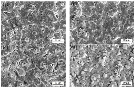
Figure 1.
SEM micrograph of the MAO coating formed with different concentrations of Y(NO3)3, at (a) 0 g/L, (b) 0.15 g/L, (c) 0.45 g/L, and (d) 0.75 g/L.
Figure 2 shows the three-dimensional images of the MAO coatings formed with different concentrations of the Y(NO3)3. Additionally, Table 1 presents the corresponding surface roughness values (Ra). The samples, Y1 (0 g/L), Y2 (0.15 g/L), Y3 (0.45 g/L), and Y4 (0.75 g/L), corresponding to Figure 2a–d, possessed average surface roughness parameter values (Ra) of 0.916 μm, 1.061 μm, 0.968 μm, and 0.705 μm, respectively. The samples Y1, Y2, and Y3 exhibited significant surface roughness with prominent protrusions, whereas sample Y4 presented the lowest surface roughness. The coating’s roughness initially increased and subsequently decreased with an increase in the Y(NO3)3 concentration. The maximum roughness was observed at a Y(NO3)3 concentration of 0.15 g/L, and the minimum roughness was achieved with a concentration of 0.75 g/L.
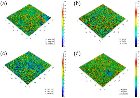
Figure 2.
Three-dimensional surface profiles of the MAO coating formed with different concentrations of Y(NO3)3, at (a) 0 g/L, (b) 0.15 g/L, (c) 0.45 g/L, and (d) 0.75 g/L.

Table 1.
Surface roughness of the MAO coating formed with different concentrations of the Y(NO3)3.
3.2. Cross-Sectional Morphology of MAO Coating
Figure 3 shows the cross-sectional morphology of the MAO coating at different concentrations of the Y(NO3)3. As depicted in Figure 3, the coatings consisted of a dense and a loose layer. The dense layer, which was in close proximity to the substrate, was thin, and its thickness did not notably fluctuate with the concentration of the Y(NO3)3. The overall thickness of the coating initially increased and then decreased at higher concentrations of the Y(NO3)3. At a concentration of 0.45 g/L Y(NO3)3, the thickest coating measured 12.09 μm. However, when the concentration was increased to 0.75 g/L Y(NO3)3, the thickness decreased to only 9.569 μm. As shown in Figure 3, the outer porous layer contained irregularly shaped micropores distributed randomly throughout. As the concentration of the Y(NO3)3 increased, the number and size of the micropores first increased and then decreased. Large micropores are evident in Figure 3a–c. The micropores depicted in Figure 3a exhibited an independent distribution, with no formation of a pore band from pore connections. Figure 3b displays an uneven coating edge with a significant variation in thickness. The outer porous layer contained numerous micropores with a large pore size. Figure 3c illustrates the relatively large pore size within the coating, with some micropores merging to create larger pores, resulting in the lowest density. Figure 3d demonstrates a random distribution of only a handful of small pores in the coating, leading to excellent compactness, and aligns with the surface morphology of the MAO coating that is illustrated in Figure 1d. Therefore, the above cross-sectional morphology confirms that the addition of an appropriate amount of yttrium nitrate to the electrolyte can significantly enhance the density of the MAO coating.
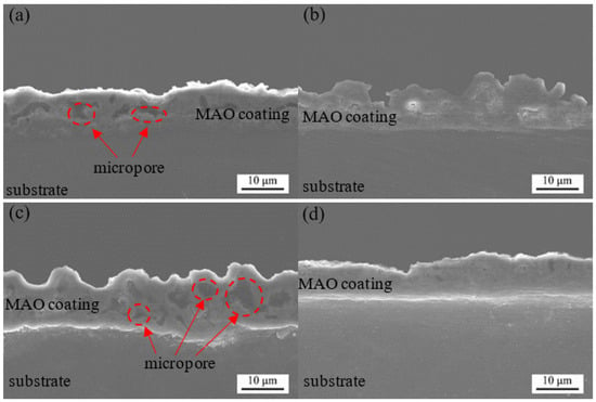
Figure 3.
Cross-sectional morphology of coatings formed with different concentrations of Y(NO3)3, at (a) 0 g/L; (b) 0.15 g/L; (c) 0.45 g/L; and (d) 0.75 g/L.
3.3. Composition Analysis of MAO Coating
The EDS analysis results of the coating surface are shown in Table 2. The coating was mainly composed of Zr, Mg, O, F, Y, Na, P, Zn, etc. The presence of the element Y indicated that the Y(NO3)3 in the electrolyte had participated in the formation of the coating and that the element Y had successfully integrated into the coating. As shown in Table 2, with the increase in the Y(NO3)3 concentration, the content of the Zr element in the coating slightly decreased, while the content of the Y element showed an increasing trend, indicating that the phase content of the Y in the coating increased. In general, at a concentration of 0.75 g/L Y(NO3)3, the highest Y content in the coating was observed.

Table 2.
Surface element and contents of coatings formed with different concentrations of Y(NO3)3 (atomic)%.
Figure 4 shows the SEM images of the coating and the distribution of the Zr and Y elements after scanning. As shown in Figure 4a from the surface element distribution, the Zr and Y elements were evenly distributed throughout the coating, indicating that both (NH4)2ZrF6 and Y(NO3)3 participated in the film formation reaction during the micro-arc oxidation process. The addition of the Y(NO3)3 did not have a significant impact on the distribution of the Zr elements. Furthermore, there was no noteworthy accumulation of the Zr and Y elements, implying that the (NH4)2ZrF6 and Y(NO3)3 were integrated into the coating via reactive doping. This implies that they first decompose into corresponding ions in the solution and then react under conditions of high temperature and high pressure. In the process of forming the coating, the corresponding oxides were produced in situ and evenly dispersed throughout the coating. Figure 4b shows the cross-sectional morphology of the MAO coating and the distribution of the Zr and Y elements in the coating. The Zr and Y elements were evenly distributed in the coating without significant agglomeration, indicating that the (NH4)2ZrF6 and Y(NO3)3 participated in the film formation reaction from the beginning to the end of the MAO process.
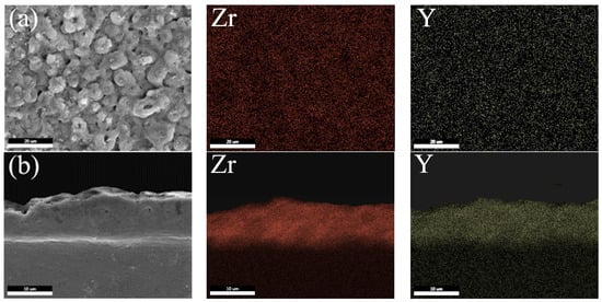
Figure 4.
Element distribution of the MAO coating formed with a Y(NO3)3 concentration of 0.75 g/L (a) Surface morphology and distribution of Zr and Y elements; and (b) Cross-sectional morphology and distribution of Zr and Y elements.
3.4. Phase Analysis of MAO Coating
Figure 5 shows the XRD patterns of the coating formed with different concentrations of Y(NO3)3. The MAO coating of sample Y1, which was prepared in an electrolyte without Y(NO3)3, consisted mainly of t-ZrO2, m-ZrO2, c-ZrO2, MgO, and MgF2 phases. Of these, t-ZrO2 was the major constituent of the ZrO2, m-ZrO2 was the supporting component, and the content of c-ZrO2 was minimal, almost negligible. This discovery supports the findings of Zhang et al. [24], who observed that the ZrO2/MgO MAO coating contained mainly m-ZrO2 and t-ZrO2 crystal structures. Samples Y2–Y4 were found to have an MAO coating primarily composed of c-ZrO2, t-ZrO2, m-ZrO2, MgO, Y2O3, and MgF2. Notably, c-ZrO2 is the most significant constituent of ZrO2, followed by t-ZrO2, whereas m-ZrO2 is the least abundant. The stable cubic phase of ZrO2 from room temperature to melting temperature is mainly due to the formation of Y2O3 in the coating [25]. When the concentration of the Y(NO3)3 was altered, there was a slight increase in the diffraction peak intensity of the ZrO2 and Y2O3. Additionally, the full width at half of the maximum of the diffraction peak at 30.921° increased gradually, indicating a gradual increase in its content in the coating, as well as a decrease in grain size resulting in grain refinement. No phase related to phosphorus was detected in any of the coatings, suggesting that the element exists in an amorphous state.
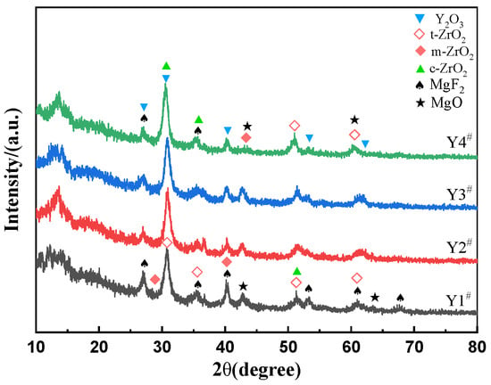
Figure 5.
XRD patterns of coatings formed with different concentrations of Y(NO3)3, Y1# (0 g/L), Y2# (0.15 g/L), Y3# (0.45 g/L), and Y4# (0.75 g/L).
Figure 6 shows the full XPS spectrum of the MAO coating and the high-resolution spectra of Y 3d, Zr 3d, O 1s, and F 1s. The peaks of Zr, O, F, Na, Mg, and Y were detected, indicating that the Y(NO3)3 participated in the film formation reaction during the micro-arc oxidation process and was successfully incorporated into the coating. Nonetheless, the Y peak was negligible from the full spectrum (Figure 6a), implying a low Y content in the coating. Based on the data presented in Figure 6b, it is evident that Y 3d had two distinct peaks, which corresponded to Y2O3 (158.9 eV) and YF3 (161.2 eV), respectively [26,27]. This could be explained by the lower melting point of YF3 compared to that of Y2O3 [28], indicating that YF3 may be the initial product formed as a result of the reaction between NaF and Y(NO3)3 in the electrolyte.
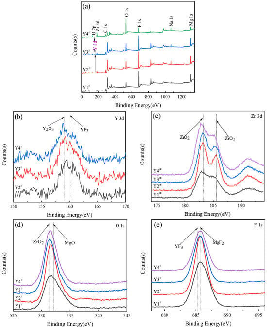
Figure 6.
XPS analysis of MAO coating formed with different concentrations of Y(NO3)3: Y1# (0 g/L), Y2# (0.15 g/L), Y3# (0.45 g/L), and Y4# (0.75 g/L). (a) XPS full spectrum; and (b–e) high-resolution spectra of Y 3d, Zr 3d, F 1s, O 1s, respectively.
As shown in Figure 6c, the Zr 3d spectrum displayed two discernible peaks at 183.2 eV and 185.5 eV, representing Zr 3d5/2 and Zr 3d3/2, respectively. Upon examination, both of these peaks signified the presence of ZrO2 [29,30]. Figure 6d illustrates a high-resolution spectrum of F 1s, which clarifies that the F element subsisted as MgF2 adjacent to the binding energy of 685.75 eV and as YF3 near 685.3 eV [31,32]. The high-resolution O 1s spectrum is displayed in Figure 6e, demonstrating the presence of two peaks near the binding energies of 531.3 eV and 532.1 eV, representing ZrO2 and MgO [33,34], respectively. The XPS spectroscopy analysis validated the results of the phase detection obtained from the XRD.
3.5. Electrochemical Corrosion Test of MAO Coatings
Figure 7 shows the polarization curves of the MAO coating and the ZK61M magnesium alloy measured at room temperature in a 3.5% NaCl solution. Table 3 records the self-corrosion potential, the corrosion current density, and the calculated polarization resistance extracted from the polarization curves. It can be seen that the self-corrosion potential of all the coating samples was significantly higher than that of the substrate (−1.594 V), with the lowest self-corrosion potential of −1.371 V for sample Y3. The corrosion potential of sample Y2 was the highest, with a value of −1.448 V. The self-corrosion potential of the other coatings also increased significantly, indicating that the addition of Y(NO3)3 can effectively improve the corrosion resistance of the coating.
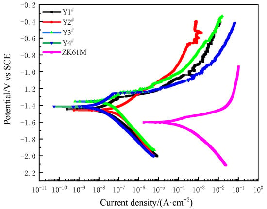
Figure 7.
Potentiodynamic polarization curves of MAO coating formed with different concentrations of Y(NO3)3 and ZK61M magnesium alloy in a 3.5% NaCl solution at room temperature: Y1# (0 g/L), Y2# (0.15 g/L), Y3# (0.45 g/L), and Y4# (0.75 g/L).

Table 3.
Parameter values of potentiodynamic polarization curves of MAO coatings formed with different concentrations of Y(NO3)3 and ZK61M magnesium alloy in a 3.5 wt.% NaCl solution at room temperature: Y1# (0 g/L), Y2# (0.15 g/L), Y3# (0.45 g/L), and Y4# (0.75 g/L).
From Table 3, it can be seen that the corrosion current densities of the Y1–Y4 coating samples were all on the same order of magnitude, which means that they were all four orders of magnitude lower than the corrosion current density of the substrate. The increase in the concentration of the Y(NO3)3 to 0.15 g/L (Y2) and 0.45 g/L (Y3) led to a rise of three orders of magnitude in the polarization resistance of the coating compared to that of the substrate. When the Y(NO3)3 concentration equaled 0.75 g/L (Y4), the corrosion current density (Icorr) reached its minimum level at 1.415 × 10⁻⁸ A·cm−2, and the polarization resistance (Rp) peaked at 1.674 × 10⁶ kΩ·cm2. This led to an increase of four orders of magnitude in the coating’s polarization resistance compared to that of the substrate. Based on the coating’s self-corrosion potential, corrosion current density, and polarization resistance, adding an appropriate amount of Y(NO3)3 can stabilize the c-ZrO2 and t-ZrO2 at room temperature, preventing phase transformation-induced cracks and ultimately enhancing the coating’s resistance to corrosion [35,36]. Simultaneously, the reduction in porosity of the Y4 sample successfully hindered the entrance of harmful corrosive agents, resulting in a superior corrosion protection for both the coating and the substrate, as well as displaying the optimal corrosion resistance performance. Li et al. similarly obtained identical findings in their examination of the pore structure of the MAO coating [37].
3.6. Friction and Wear Properties
As shown in Figure 8 and Figure 9, the friction coefficient of the magnesium alloy substrate exhibited considerable fluctuations over time, initially escalating to 0.586 within 0.198 s and subsequently oscillating between 0.404 and 0.917. Since the magnesium alloy substrate is relatively soft and viscous, the friction coefficient remained unstable, culminating in a final average friction coefficient of 0.598. The friction coefficient of sample Y1 was 0.536, and that of sample Y2 was 0.517, which was slightly lower than the former. However, there was a clear spike in the friction coefficient curve of the coating at approximately 7.5 min after the beginning of the experiment, indicating damage to and failure of the coating. Sample Y3 had a friction coefficient of 0.553, and its corresponding friction coefficient curve showed an upward trend, demonstrating damage to and failure of the coating after a clear spike at 17.75 min. The friction coefficient for sample Y4 was the lowest among all the coating samples, measuring 0.414. However, around the 8 min mark, the curve flattened out and stabilized. Initially, its friction coefficient curve reached a minimum value of approximately 0.2 at around 37 s and then gradually increased. During this process, the fluctuations in the friction coefficient decreased gradually. This may have been caused by the presence of spherical microprojections on the surface of the coating during the initial wear stage, leading to significant unevenness. As the microprojections wore down, the surface became smoother, resulting in a reduction in the fluctuation of the friction coefficient.
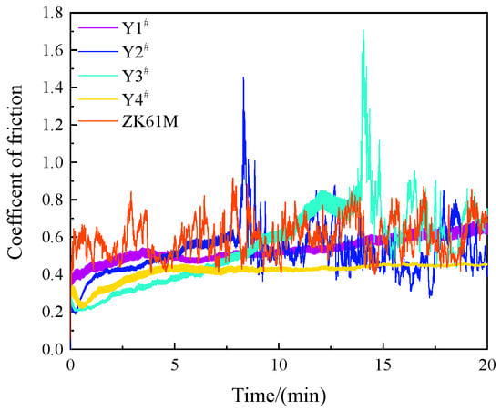
Figure 8.
Variation of friction coefficient of MAO coatings formed with different concentrations of Y(NO3)3: Y1# (0 g/L), Y2# (0.15 g/L), Y3# (0.45 g/L), and Y4# (0.75 g/L).
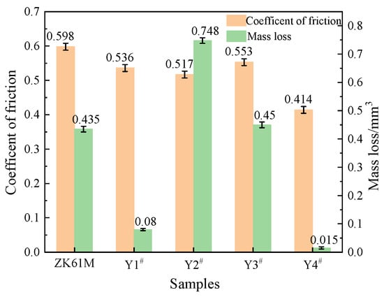
Figure 9.
Friction coefficient and mass loss of MAO coating formed with different concentrations of Y(NO3)3: Y1# (0 g/L), Y2# (0.15 g/L), Y3# (0.45 g/L), and Y4# (0.75 g/L).
The comprehensive analysis of the friction coefficient and wear volume of the coating suggests that the MAO coating with a Y(NO3)3 content of 0.75 g/L (Y4) has the best friction and wear properties. The friction coefficient of Y4 is the lowest, decreasing by 30.77% compared to the substrate. Furthermore, its wear volume is also the smallest of the four samples, decreasing by 96.55% compared to the substrate. This outcome indicates that the addition of Y(NO3)3 enhances the wear resistance of the coating. The impact of Y(NO3)3 on the wear resistance of MAO coatings is primarily attributed to the development of Y2O3 within the coating. This reduction of micropores in the coating improves its compactness and reinforces the particle strengthening effect.
4. Conclusions
In this work, the effect of the content of yttrium nitrate on the microstructure, wear resistance, and corrosion resistance of magnesium alloy using micro-arc oxidation (MAO) coatings was investigated. The influence of the yttrium nitrate content on the evolution of the coating microstructure and its properties was also analyzed. The following conclusions were drawn:
- When the yttrium nitrate content in the electrolyte is increased, the pore size and the number of micropores on the MAO coating surface decrease, and the MAO coating compactness increases. The MAO coating consists mainly of c-ZrO2, t-ZrO2, m-ZrO2, MgO, Y2O3, and MgF2.
- When the concentration of the Y(NO3)3 is 0.75 g/L, sample Y4 exhibits the best corrosion resistance. The corrosion current density (Icorr) of sample Y4 is 1.415 × 10⁻⁸ A·cm−2, which is four orders of magnitude lower than the substrate. The polarization resistance (Rp) of sample Y4 is 1.674 × 10⁶ kΩ·cm2, which is four orders of magnitude higher than the substrate.
- The friction and wear test results show that, when the amount of the yttrium nitrate in the electrolyte is 0.75 g/L, sample Y4 has the best wear resistance. This is related to the reduction in micropores, the improvement in compactness, and the strengthening effect of the Y2O3 phase in the coating.
In general, the preliminary results of this paper show that a ZrO2-Y2O3 composite coating can be formed on the surface of a magnesium alloy using MAO after adding yttrium nitrate to the zirconate electrolyte system. When the yttrium nitrate content was increased, the corrosion resistance and wear resistance of the coating were improved to a certain extent. However, methods to accurately control the content of the ZrO2-Y2O3 and the phase structure of the ZrO2 in the coating, to improve the compactness of the coating, and to greatly improve the properties of the coating are worth further investigation.
Author Contributions
Conceptualization and formal analysis, H.L.; methodology and validation, H.L. and Y.W.; software, Y.W., J.G. and S.L.; resources, supervision, project administration, and funding acquisition, H.L. and Y.C.; date curation, Y.W. and J.G.; investigation, writing—original draft preparation, and visualization, H.L.; writing—review and editing, H.L. and Y.C. All authors have read and agreed to the published version of the manuscript.
Funding
This research was supported by the Major Science and Technology Project of Shaanxi Province (China), grant number 2020zdzx04-03-02, and the Key R&D project of Shaanxi Province (China), grant number 2022SF-294.
Institutional Review Board Statement
Not applicable.
Informed Consent Statement
Not applicable.
Data Availability Statement
Data are contained within the article.
Conflicts of Interest
The authors declare no conflict of interest.
References
- Deng, Y.; Hu, A.; Xiao, X.; Jia, B. Experimental and numerical investigation on the ballistic resistance of ZK61m magnesium alloy plates struck by blunt and ogival projectiles. Int. J. Impact Eng. 2021, 158, 104021. [Google Scholar] [CrossRef]
- Chen, S.; Zhao, W.; Yan, P.; Qiu, T.; Gu, H.; Jiao, L.; Wang, X. Effect of milling surface topography and texture direction on fatigue behavior of ZK61M magnesium alloy. Int. J. Fatigue 2022, 156, 106669. [Google Scholar] [CrossRef]
- Chena, X.; Xua, C.; Jin, H.; Qin, S. Hot compression deformation behavior of extruded ZK61M magnesium alloy and establishment of constitutive equation. Procedia Manuf. 2020, 50, 637–641. [Google Scholar] [CrossRef]
- Štrbák, M.; Kajánek, D.; Knap, V.; Florková, Z.; Pastorková, J.; Hadzima, B.; Goraus, M. Effect of Plasma Electrolytic Oxidation on the Short-Term Corrosion Behaviour of AZ91 Magnesium Alloy in Aggressive Chloride Environment. Coatings 2022, 12, 566. [Google Scholar] [CrossRef]
- Lee, C.; Lee, J.; Jian, S.; Chen, C.; Aktug, S.; Ger, M. The effect of fluoride on the formation of an electroless Ni-P plating film on MAO-coated AZ31B magnesium alloy. J. Mater. Res. Technol. 2022, 19, 542–556. [Google Scholar] [CrossRef]
- Zhang, Y.; Shen, X. Facile fabrication of robust superhydrophobic coating for enhanced corrosion protection on AZ91 magnesium alloy by electroless Ni-B/GO plating. Surf. Coat. Technol. 2023, 455, 129213. [Google Scholar] [CrossRef]
- Davoodi, F.; Atapour, M.; Blawert, C.; Zheludkevich, M. Wear and corrosion behavior of clay containing coating on AM 50 magnesium alloy produced by aluminate-based plasma electrolytic oxidation. Nonferrous Met. Soc. China 2021, 31, 3719–3738. [Google Scholar] [CrossRef]
- Toulabifard, A.; Rahmati, M.; Raeissi, K.; Hakimizad, A.; Santamaria, M. The Effect of Electrolytic Solution Composition on the Structure, Corrosion, and Wear Resistance of PEO Coatings on AZ31 Magnesium Alloy. Coatings 2020, 10, 937. [Google Scholar] [CrossRef]
- Yong, J.; Li, H.; Li, Z.; Chen, Y.; Wang, Y.; Geng, J. Effect of (NH4)2ZrF6, Voltage and Treating Time on Corrosion Resistance of Micro-Arc Oxidation Coatings Applied on ZK61M Magnesium Alloys. Materials 2021, 14, 7410. [Google Scholar] [CrossRef]
- Zhuang, J.; Guo, Y.; Xiang, N.; Xiong, Y.; Hua, Q.; Song, R. A study on microstructure and corrosion resistance of ZrO2-containingPEO coatings formed on AZ31 Mg alloy in phosphate-based electrolyte. Appl. Surf. Sci. 2015, 357, 1463–1471. [Google Scholar] [CrossRef]
- Mashtalyar, D.; Imshinetskiy, I.; Nadaraia, K.; Gnedenkov, A.; Sinebryukhov, S.; Ustinov, A.; Samokhin, A.; Gnedenkov, S. Influence of ZrO2/SiO2 nanomaterial incorporation on the properties of PEO layers on Mg-Mn-Ce alloy. J. Magnes. Alloys 2022, 10, 513–526. [Google Scholar] [CrossRef]
- Rehman, Z.; Choi, D. Investigation of ZrO2 nanoparticles concentration and processing time effect on the localized PEO coatings formed on AZ91 alloy. J. Magnes. Alloys 2019, 7, 555–565. [Google Scholar] [CrossRef]
- Rehman, Z.; Shin, S.; Lim, H.; Koo, B. Transformation of plasma electrolytic oxidation coatings from crater to cluster–based structure with increase in DC voltage and the role of ZrO2 nanoparticles. Surf. Coat. Technol. 2017, 311, 383–390. [Google Scholar] [CrossRef]
- Askarnia, R.; Sobhani, M.; Zare, M.; Aghamohammadi, H.; Staji, H. Incorporation of Al2O3 and ZrO2 ceramics to AZ31 magnesium alloys composite coating using micro-arc oxidation method. J. Mech. Behav. Biomed. Mater. 2023, 141, 105784. [Google Scholar] [CrossRef] [PubMed]
- Chen, X.; Zhang, M.; Zhang, D.; Cai, L.; Song, H.; Zeng, D. The effect of addition of K2ZrF6 on the structures and properties of AZ31 magnesium alloy MAO coating. J. Alloys Compd. 2023, 966, 171474. [Google Scholar] [CrossRef]
- Gao, Y.; Zhao, L.; Yao, X.; Hang, R.; Zhang, X.; Tang, B. Corrosion behavior of porous ZrO2 ceramic coating on AZ31B magnesium alloy. Surf. Coat. Technol. 2018, 349, 434–441. [Google Scholar] [CrossRef]
- Tang, M.; Shao, Y.; Feng, Z.; Wang, W.; Li, G.; Yan, Z.; Zhang, R. Self-sealing Microarc Oxidation Coating Mainly Containing ZrO2 and Nano Mg2Zr5O12 on AZ91D Mg Alloy. Int. J. Electrochem. Sci. 2020, 15, 12447–12461. [Google Scholar] [CrossRef]
- Chen, J.; Yang, Y.; Etim, I.; Tan, L.; Yang, K.; Misra, R.; Wang, J.; Su, X. In vitro degradation, wear property and biocompatibility of nano-Y2O3-containing micro-arc oxidation coating on ZK60 alloy. Nonferrous Met. Soc. China 2023, 33, 1411–1424. [Google Scholar] [CrossRef]
- Han, B.; Yang, Y.; Deng, H.; Chen, Y.; Yang, C. Plasma-Electrolytic-Oxidation Coating containing Y2O3 Nanoparticles on AZ91 Magnesium Alloy. Int. J. Electrochem. Sci. 2018, 13, 5681–5697. [Google Scholar] [CrossRef]
- Zhao, J.; Ouyang, K.; Xie, X.; Zhang, J. Influence of Y2O3/Nd2O3 Particles Additive on the Corrosion Resistance of MAO Coating on AZ91D Magnesium Alloy. Int. J. Electrochem. Sci. 2017, 12, 2400–2411. [Google Scholar] [CrossRef]
- Tjiang, F.; Ye, L.; Huang, Y.; Chou, C.; Tsai, D. Effect of processing parameters on soft regime behavior of plasma electrolytic oxidation of magnesium. Ceram. Int. 2017, 43, S567–S572. [Google Scholar] [CrossRef]
- Yao, W.; Wu, L.; Wang, J.; Jiang, B.; Zhang, D.; Serdechnova, M.; Shulha, T.; Blawert, C.; Zheludkevich, M.; Pan, F. Micro-arc oxidation of magnesium alloys: A review. J. Mater. Sci. Technol. 2022, 118, 158–180. [Google Scholar] [CrossRef]
- Hadzima, B.; Kajánek, D.; Jambor, M.; Drábiková, J.; Brezina, M.; Buhagiar, J.; Pastorková, J.; Jacková, M. PEO of AZ31 Mg Alloy: Effect of Electrolyte Phosphate Content and Current Density. Metals 2020, 10, 1521. [Google Scholar] [CrossRef]
- Zhang, Z.; Yang, Z.; Qian, W.; Chen, Y.; Xu, Y.; Xu, X.; Zhao, Q.; Li, H.; Zhao, Q.; Zhan, H. Achieving enhanced toughness of a nanocomposite coating by lattice distortion at the variable metallic oxide interface. Mater. Des. 2022, 224, 111316. [Google Scholar] [CrossRef]
- Wen, T.; Yuan, L.; Liu, T.; Sun, Q.; Jin, E.; Tian, C.; Yu, J. Enhanced ionic conductivity and thermal shock resistance of MgO stabilized ZrO2 doped with Y2O3. Ceram. Int. 2020, 46, 19835–19842. [Google Scholar] [CrossRef]
- Ma, H.; Park, Y.; Kim, M.; Kim, H.; Ko, J.; Lee, J.; Kim, J.; Lee, H. Physiochemical etching characteristics and surface analysis of Y2O3-MgO nanocomposite under different CF4/Ar/O2 plasma atmospheres. Appl. Surf. Sci. 2023, 641, 158483. [Google Scholar] [CrossRef]
- Peng, H.; Peng, W.; Jiang, J.; Shi, H.; Zhu, J.; Xu, J.; Yu, F. Synthesis of silicate clay minerals-based novel Mt/YF3:Eu3+ nanocomposites for regulated luminescent intensity-quantum yield-fluorescence lifetime. Ceram. Int. 2023, 49, 34119–34128. [Google Scholar] [CrossRef]
- So, J.; Kim, M.; Kwon, H.; Maeng, S.; Choi, E.; Chung, C.; Yun, J. Investigation of contamination particles generation and surface chemical reactions on Al2O3, Y2O3, and YF3 coatings in F-based plasma. Appl. Surf. Sci. 2023, 629, 157367. [Google Scholar] [CrossRef]
- Lee, J.; Jang, K.; Lee, S.; Mo, C.; Kim, H.; Park, K.; Kim, J.; Bang, J.; Jung, I.; Kim, J.; et al. Mechanical properties of TiC reinforced MgO–ZrO2 composites via spark plasma sintering. Ceram. Int. 2023, 49, 17255–17260. [Google Scholar] [CrossRef]
- Jiang, C.; Shi, L.; Xie, T.; Jiang, J.; An, Y.; Chen, Y.; Zhao, Q.; Li, Y. Effect of K2ZrF6 concentration on thermal ablation resistance of ZrO2/TiO2 composite ceramic coatings on TC4 alloy. J. Alloys Compd. 2023, 968, 172162. [Google Scholar] [CrossRef]
- Liu, C.; Zhang, W.; Xu, T.; Li, H.; Jiang, B.; Miao, X. Preparation and corrosion resistance of a self-sealing hydroxyapatite- MgO coating on magnesium alloy by microarc oxidation. Ceram. Int. 2022, 48, 13676–13683. [Google Scholar] [CrossRef]
- Cruz, B.; Lilge, T.; Andrade, A.; Moura, R.; Alencar, M.; Jr, J.; Valerio, M.; Macedo, Z. One-step synthesis of YF3: Nd rod-like particles for contactless luminescent thermometers. Opt. Mater. 2022, 131, 112661. [Google Scholar] [CrossRef]
- Wu, X.; Tan, M.; Geng, H.; Zhao, S.; Xu, B.; Tan, Y. Effect of crystal structure of ZrO2 catalyst on isobutene synthesis from CO hydrogenation. J. Fuel Chem. Technol. 2023, 4, 473–481. [Google Scholar] [CrossRef]
- Zhu, J.; Li, H.; Li, Z.; Wang, Y.; Chen, Y.; Geng, J. Effect of Oxidation Time on the Structure and Corrosion Resistance of Micro-Arc Oxidation Coating of AZ91D Magnesium Alloy in (NH4)2ZrF6 Electrolyte System. Coatings 2022, 12, 1538. [Google Scholar] [CrossRef]
- Daroonparvar, M.; Yajid, M.; Gupta, R.; Yusof, N.; Bakhsheshi-rad, H.; Ghandvar, H.; Ghasemi, E. Antibacterial activities and corrosion behavior of novel PEO/nanostructured ZrO2 coating on Mg alloy. Trans. Nonferrous Met. Soc. China 2018, 28, 1571–1581. [Google Scholar] [CrossRef]
- Wang, M.; Li, C.; Yen, S. Electrolytic MgO/ZrO2 duplex-layer coating on AZ91D magnesium alloy for corrosion resistance. Corros. Sci. 2013, 76, 142–153. [Google Scholar] [CrossRef]
- Li, J.; Zhang, Z.; Guo, Z.; Yang, Z.; Qian, W.; Chen, Y.; Li, H.; Zhao, Q.; Xing, Y.; Zhao, Y. Improved corrosion resistance of ZrO2/MgO coating for magnesium alloys by manipulating the pore structure. J. Mater. Res. Technol. 2023, 24, 2403–2415. [Google Scholar] [CrossRef]
Disclaimer/Publisher’s Note: The statements, opinions and data contained in all publications are solely those of the individual author(s) and contributor(s) and not of MDPI and/or the editor(s). MDPI and/or the editor(s) disclaim responsibility for any injury to people or property resulting from any ideas, methods, instructions or products referred to in the content. |
© 2023 by the authors. Licensee MDPI, Basel, Switzerland. This article is an open access article distributed under the terms and conditions of the Creative Commons Attribution (CC BY) license (https://creativecommons.org/licenses/by/4.0/).