Article

High-Temperature Heat Treatment of Plasma Sprayed Ti–Si–C–Mo Coatings

1
Tianjin Key Laboratory of Materials Laminating Fabrication and Interface Control Technology, School of Materials Science and Engineering, Hebei University of Technology, Tianjin 300132, China
2
College of Mechanical Engineering, Suzhou University of Science and Technology, Suzhou 215000, China
*
Authors to whom correspondence should be addressed.
Coatings 2024, 14(1), 109; https://doi.org/10.3390/coatings14010109
Submission received: 30 November 2023 / Revised: 8 January 2024 / Accepted: 12 January 2024 / Published: 15 January 2024
(This article belongs to the Special Issue Advanced Materials and Surface Protection)

Abstract

:
In this work, the effect of 800 °C and 1100 °C post-heat treatment on the plasma spraying of Ti–Si–C–xMo (x = 1.0, 1.5) composite coatings was investigated. The composite coatings were composed of TiC, Ti3SiC2, Ti5Si3 and Mo5Si3 reacted phases. After heat treatment, the Ti3SiC2 and Mo5Si3 phases increased. The coating microhardness decreased by 16% and 18% for Ti–Si–C–1.0Mo and Ti–Si–C–1.5Mo coatings, respectively, after heat treatment at 1100 °C. Fracture toughness increased by 16% for the Ti–Si–C–1.5Mo coating after heat treatment at 1100 °C, which was mainly due to the heat treatment promoting Ti3SiC2 formation, healing micro-cracks, reducing the internal stress and making the microstructure dense. The coating friction coefficient before and after heat -treatment was between 0.4 and 0.6. After heat treatment, the wear amount of the coating was first reduced and then increased, and the minimum wear loss occurred after heat treatment at 800 °C. The wear mechanism was mixed abrasive wear, adhesive wear and tribo-oxidation wear.

1. Introduction

For metallic components worked in complex environments, it is necessary to prepare protective coatings for their surfaces. Among the surface-coating materials (metals, organics and ceramics), ceramic materials have an advantage in terms of their properties, such as their high hardness, good abrasive resistance and great high-temperature performance [1,2,3]. Up to now, the methods used to prepare ceramic coatings include physical/chemical vapor deposition [4], plasma spraying [5], laser cladding [6], etc. Among these methods, plasma spraying has been most commonly chosen by many researchers to prepare ceramic coatings, which is because of its technical characteristics (high flame temperature, fast deposition rate, simple process, etc.) [7,8,9]. Wang et al. [10] fabricated LaMgA111O19 thick ceramic coatings using the plasma spraying method. Hashemi et al. [11] prepared Cr2O3–20YSZ and Cr2O3–20YSZ–10SiC ceramic coatings using the plasma spraying method.
Considering the high melting point of the ceramics, the reactive plasma spraying (RPS) method has been proposed to prepare ceramic coatings, wherein ceramic phases could be synthesized from the reaction of raw materials in the high-temperature plasma flame [12,13,14,15]. Shao et al. [16] deposited ZrC–ZrSi2 coatings via the RPS method. Sun et al. [17] in situ synthesized Ti5Si3–TiC coatings via the RPS method using Ti-Si-C powders. Sun et al. [18] prepared TiC–Ti5Si3 coatings via the RPS method using Ti–Si–sucrose powders. Recently, Wang et al. [19] fabricated NbB2–NbC coatings via ex situ (plasma spraying NbB2–NbC mixed powders) and in situ (plasma spraying Nb–B4C mixed powders) methods, respectively. They found that the properties of the coatings obtained via in situ method were better than those of the coatings obtained via the ex situ method. Cui et al. [20] fabricated ZrB2–ZrC coatings via ex situ (plasma spraying ZrB2–ZrC mixed powders) and in situ (plasma spraying Zr–B4C mixed powders) methods, respectively. They also found that the in situ ZrB2–ZrC coatings exhibited more excellent performance. Wang et al. [21] deposited CrB2–Cr3C2 coatings by plasma spraying CrB2–Cr3C2 powders and Cr–B4C powders. They compared the microstructure and properties of the coating and found that the Cr–B4C powders were suitable to be used to plasma spray CrB2–Cr3C2 coatings with high quality and excellent performance. Based on these studies, reactive plasma spraying is an effective method for the preparation of ceramic coatings.
To improve the properties of the materials, the heat treatment method has often been adopted [22,23]. Similarly, many researchers have improved coating performance by coating post-heat treatment. For instance, Ghadami et al. [24] found that coating post-heat treatment was beneficial for the sprayed coating’s microstructure and that a higher heating temperature could improve adhesive strength. Varis et al. [25] found that coating post-heat treatment could modify the microstructure and improve the resistance to abrasive wear and cavitation erosion of spraying tool steel coatings. Zhao et al. [26] improved the microhardness and fracture toughness of Ti3SiC2-based coatings by 13% and 25%, respectively, after heat-treatment at 700 °C.
Recently, we fabricated TiC–Ti5Si3–Ti3SiC2–Cr coatings by plasma spraying Ti–Si–C–Cr mixed powders and found that their coating performance was mainly related to the phase composition [27]. After heat treatment at 800 °C and 1100 °C, element diffusion allowed for a uniform microstructure and Ti3SiC2 phase formation, after which coating performance was improved [28]. As reported, Mo as a metal additive was also useful for enhancing the mechanical properties of the plasma spray coatings [29]. Thus, we prepared TiC–Ti5Si3–Ti3SiC2–Mo coatings by plasma spraying Ti–Si–C–Mo mixed powders and found that coating performance was improved (hardness enhanced by 16% and fracture toughness enhanced by 25%) [30]. Compared with Cr addition, Mo addition was more effective at improving coating performance. However, there are few studies on the heat treatment of TiC–Ti5Si3–Ti3SiC2–Mo coatings so far. In this work, the purpose was to study the effect of heat treatment on TiC–Ti5Si3–Ti3SiC2–Mo coatings, especially the phase composition and mechanical properties. In addition, tribological performance was also discussed before and after heat treatment.

2. Experimental Details

The irregular raw-powder materials used in this experiment were Ti powder (D90 Size: 30–45 μm), Si powder (D90 Size: 15–30 μm), graphite powder (D90 Size: 5 μm), and Mo powder (D90 Size: 5–10 μm), which were purchased from Beijing Xingrongyuan Technology Co., Ltd. (Beijing, China). These powders were mixed with a dispersant (polyvinyl alcohol), deionized water and sodium carboxymethylcellulose according to the different molar ratios (Ti:Si:graphite:Mo = 3:1:2:x, x = 1.0, 1.5), to make a slurry. The mixed slurry was spray-dried to obtain the Ti–Si–graphite–Mo feedstock of the plasma spray. The speed of the atomizer was 18,000 r/min, the slurry conveying rate was 5 L/h, the temperature of the air inlet was 230~280 °C, and the temperature of the air outlet was 100~130 °C. Ni-10 wt.% Al powders (size: 45–60 μm) were sprayed firstly as bonding coatings. The Ti–Si–C–Mo coating was deposited on a steel block (45# steel, size: 10 mm × 10 mm × 10 mm) matrix using plasma spraying equipment (GP-80, Jiangsu Yeyuan Spraying Machinery Factory, Jiujiang, China) with the following parameters: a protective gas flow rate (Ar) of 80 L/min; current of 500 A; voltage of 70 V; spraying distance of 100 mm; coating thickness of 100 μm (Ni/Al)/300~400 μm. Finally, the deposited coating was heat-treated in a vacuum atmosphere (10−3 Pa) in a tube furnace (Hefei Kejing Material Technology Co., Ltd., Hefei, China), and the specimen was heated to 800 °C and 1100 °C with a raised rate of 6 °C/min. It was held for 1h after reaching the specified temperature and cooled in the furnace.
The phase structure of the deposited coating was determined via an X-ray diffraction (XRD, Rigaku D/max2500, Rigaku, Tokyo, Japan) system (scattering angle: 20°–90°, scanning rate: 6 °/min). Copper with a wavelength of 1.542 Å was used as the radiation source; the test voltage was 40 kV and the current was 35 mA. Using a scanning electron microscope (SEM, S-4800, Hitachi, Tokyo, Japan) to observe the surface and cross-section microscopy of the deposited coating (firstly, we polished the samples with sandpaper and a polishing agent; secondly, we cleaned the samples and dried them; finally, we fixed the samples on conductive tape). The element distribution was analyzed via energy dispersive spectroscopy (EDS) and using and electron probe microanalyzer (EPMA, JXA-8530, JEOL, Tokyo, Japan). The microhardness of the deposited coating was measured using a Vickers indenter (HMV-G, Shimadzu, Kyoto, Japan) with a load of 200 g and holding time of 15 s (repeated 15 times to ensure accuracy). Fracture toughness (load: 300 g; holding time: 15 s) was calculated according to the formula K 1 c = 6.115 × 10 4 ( P a 2 / c 3 ) , whereas P is the load (N), a is half of the diagonal of the indentation (m), c is the half of the diagonal of the crack at the tip of the indentation (m). A pin-to-disc sliding test was performed on the coating using a tribometer (SFT-2M, Lanzhou Zhong Ke Kai Hua Technology Development Co., LTD, Lanzhou, China) with a GCr15 friction pair (sliding speed: 300 r/min; sliding load: 30 N; sliding time: 30 min), and then er weigh the wear loss of the sample using the balance and observed wear tracks by using the SEM.

3. Results and Discussions

Figure 1 shows the XRD of the Ti–Si–C–1.0/1.5Mo coating deposited and after heat treatment. It can be seen that TiC (JCPDF#65-8807, JCPDF#65-8804, and JCPDF#65-8417), Ti3SiC2 (JCPDF#48-1826 and JCPDF#89-1356), Ti5Si3 (JCPDF#65-3597 and JCPDF#78-1429) and Mo5Si3 (JCPDF#76-1578 and JCPDF#89-5119) were detected, which indicates that the chemical metallurgical reaction of the original powder occurred during the spraying process. The appearance of Mo diffraction peaks (JCPDF#65-7442, JCPDF#89-5023, and JCPDF#89-5156) indicates that the chemical metallurgical reaction in the spraying process was not sufficient. After 800 °C and 1100 °C of heat treatment, the main coating phase structures were TiC, Ti3SiC2, Ti5Si3 and Mo5Si3, indicating that heat treatment did not change the coating phase structure. The diffraction peak intensities of TiC and Ti5Si3 both decreased after the different temperatures of heat treatment. The 1100°C heat treatment had a greater effect on the reduction in the TiC and Ti5Si3 diffraction peak intensity than that of 800 °C heat treatment. After heat treatment at 800 °C and 1100 °C, the diffraction peak intensities of Ti3SiC2 and Mo5Si3 increased. The above results suggest that heat treatment could increase the content of Ti3SiC2 and Mo5Si3 phases in the Ti-Si-C-1.0/1.5Mo coating.
The polished surface morphology of Ti–Si–C–1.0/1.5Mo coatings before and after heat treatment at 800 °C are shown in Figure 2 There are structural characteristics such as micro-cracks, pores, unmelted particles, light/gray/dark-gray/black areas on the surface. Based on the previous research’s results, the deposition and solidification rate during the spraying process were fast, and the above structural characteristics were easy to form in the coating [31,32]. After 800 °C and 1100 °C heat treatment, the micro-cracks of the Ti–Si–C–1.0/1.5Mo coating showed a tendency to heal.
To distinguish the light/gray/dark-gray/black areas of the coating surface, an EPMA analysis of Ti–Si–C–1.0/1.5Mo coating surfaces before and after heat treatment at 800 °C and 1100 °C was performed, and the coating surface EPMA analysis is shown in Figure 3 Usually, a color from red to black represents element content from high to low. As seen, Ti/Si/C/Mo elements are detected in the coating before and after heat treatment. The light region shows red Mo and blue/black Ti/Si/C, so the light region can be defined as an unreacted metal, Mo. This also indicates the insufficient chemical metallurgical reaction during the coat-spraying process. Part of the black region shows black Si and blue/black Ti/C/Mo, so this black region can be defined as unresponsive Si. Part of the black area shows red C and blue/black Ti/Si/Mo, so this black area can be defined as unreacted graphite. The presence of unreacted Si and graphite also indicates that the reaction during coat-spraying is insufficient. The dark-gray area and some gray areas show red/yellow/green Ti/Si/C and blue/black Mo, so these region can be defined as the phase produced by the metallurgical reaction of Ti/Si/C elements. Some gray areas show Mo/Si and blue/black Ti/C in red/yellow/green, so this region can be defined as the phase formed from the metallurgical reaction between Mo and Si. After heat treatment at 800 °C and 1100 °C, the coating micro-cracks tended to heal, the element distribution tended to be homogeneous, and the Mo-Si region increased (indicating that the Mo-Si phase increased), which was mainly because the Ti/Si/C/Mo elements diffused during the heat treating process.
Figure 4 shows the polished cross-sectional morphology and EDS element distribution of the Ti–Si–C–1.0Mo coating after being heat-treated at 1100 °C. It can be seen that the layered structure did not change after heat treatment. Similar to the surface topography features, the coating’s cross-sectional morphology also has structural features such as healed micro-cracks, pores, unmelted particles, and light/gray/dark-gray/black areas. In addition, the boundaries of the light/gray/dark-gray/black areas became blurred, and the particle layer interface was also blurred. Ti/Si/C/Mo elements were distributed in coating layers, and after heat treatment at 1100 °C, the distribution of the elements in the coating was more uniform. According to the above XRD, SEM and EPMA analysis, heat treatment can promote the diffusion of Ti/Si/C/Mo elements, thereby promoting the coating phase’s structure to be denser.
Figure 5 shows the microhardness and fracture toughness of the heat-treated Ti–Si–C–1.0/1.5Mo coating. As seen, the Ti–Si–C–1.0Mo coating average microhardness was HV 1394. After heat treatment at 800 °C, it reduced to HV 1187. After heat treatment at 1100 °C, it reduced to HV 1171, which is 16% lower than that of the raw coating. The Ti–Si–C–1.5Mo coating’s average microhardness was HV 1400. After heat treatment at 800 °C, it reduced to HV 1209. After heat treatment at 1100 °C, it reduced to HV 1145, which is 18% lower than that of the raw coating. This decrease in microhardness is mainly due to the 1100 °C and 800 °C heat treatment increasing the soft phase Ti3SiC2’s formation and lowering the internal stress. The Ti–Si–C–1.0Mo coating fracture toughness is 3.35 MPa·m1/2. After heat treatment at 800 °C, it decreased to 3.303 MPa·m1/2. After heat treatment at 1100 °C, it reduced to 3.227 MPa·m1/2, which is 3% less than that of the raw coating. The Ti–Si–C–1.5Mo coating’s fracture toughness was 2.93 MPa·m1/2. After heat treatment at 800 °C, it increased to 3.362 MPa·m1/2. After heat treatment at 1100 °C, it increased to 3.413 MPa·m1/2, which represents an increase of 16% compared with that of the raw coating. The heat treatment increasing the formation of the ductile phase, Ti3SiC2, microcrack healing, and microstructure densification, resulted in an increased in the coating’s fracture toughness.
Figure 6 shows the average friction coefficient (calculated based on a stable stage, not containing the running-in period) and wear weight loss of the heated Ti–Si–C–1.0/1.5Mo coatings. The friction coefficient before and after heat treatment changed little, and was 04~0.6. After heat treatment, the wear weight loss of the coating was first reduced and then increased, and the minimum wear weight loss occurred after being heated at 800 °C.
Figure 7 shows the 800 °C and 1100 °C heat-treated coatings’ wear tracks. There were pits, granular abrasive chips and laminar cracks on the wear track surface. After heat treatment, the coating’s granular grinding chips and dark-gray areas increased, and there were more fatigue cracks, which indicated that the wear characteristics of the coating changed. For the heated Ti–Si–C–1.0Mo composite coating at 1100 °C, the abrasive chips and dark-gray areas further increased, and the fatigue cracks became more obvious.
Figure 8 shows the distribution of EDS elements in the wear track of the heated Ti–Si–C–1.0Mo coating. The Ti/Si/C/Mo elements were detected, and the Fe and O elements were also detected (mainly corresponding to the dark gray area). The presence of the Fe element indicates that the friction pair material was transferred during friction, which is related to its relatively low hardness. The appearance of the O element indicates that tribo-oxidation occurred during friction, which is caused by the flash temperature generated during friction. It can be determined that the wear mechanism was abrasive wear, coupled with adhesive wear and friction oxidation wear according to the above analysis.
Figure 9 shows the wear track morphology of the Ti–Si–C–1.5Mo coating after being heated at 800 °C and 1100 °C. There are large pits and layer cracks, and a small amount of granular grinding chips in the wear track. In addition, there is a large number of dark-gray areas on the wear track surface. After heat treatment at 800 °C and 1100 °C, the pit sizes became smaller, the layer crack area became less, the granular grinding chip changed little, and the number of dark-gray areas became smaller with the areas becoming larger. Figure 10 shows the distribution of EDS elements on the wear track surface. As seen, Ti/Si/C/Mo elements were found in the wear tracks before and after heat treatment. Fe and O elements were also detected (mainly corresponding to dark-gray areas). From the above research and analysis, it can be seen that the friction pair materials were transferred under the action of friction due to their relatively low microhardness during the friction process, and they adhered to the coating surface, which in turn led to the Fe element being detected on the wear track’s surface. In addition, it is easy to generate an instantaneous high temperature (flash temperature) during the friction process, causing the oxidation of the materials in the wear track, which in turn leads to the O element being detected. Based on an analysis of Figure 9 and Figure 10, it can be determined that the wear mechanisms of the heated Ti–Si–C–1.5Mo composite coating were mixed abrasive wear, adhesive wear and tribo-oxidation wear.

4. Conclusions

In this study, Ti–Si–C–1.0/1.5Mo coatings were prepared, and the mechanical properties and microstructure evolution of them after heat treatment at 800 °C and 1100 °C were investigated. The conclusions are as follows:
(1)
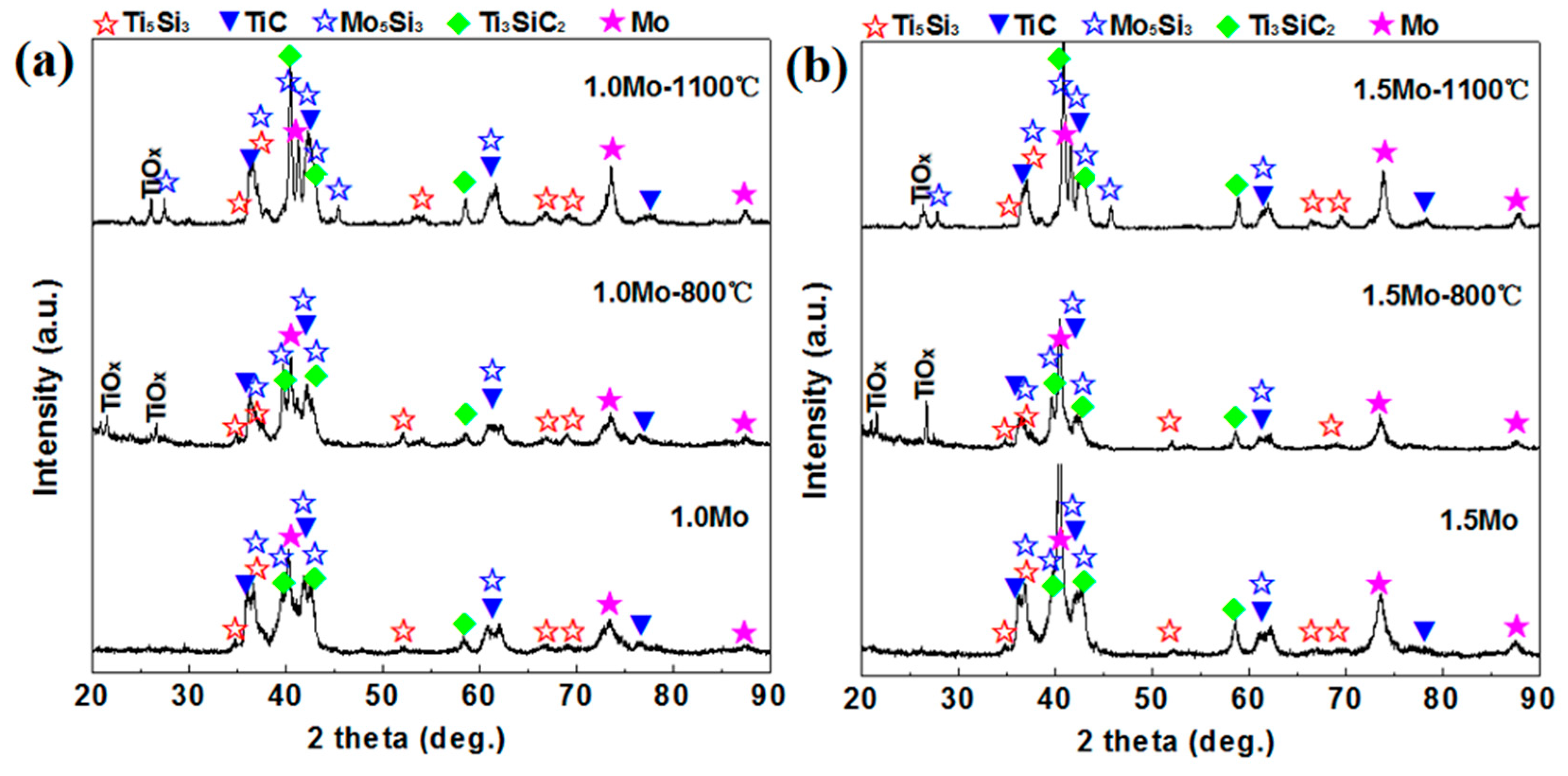
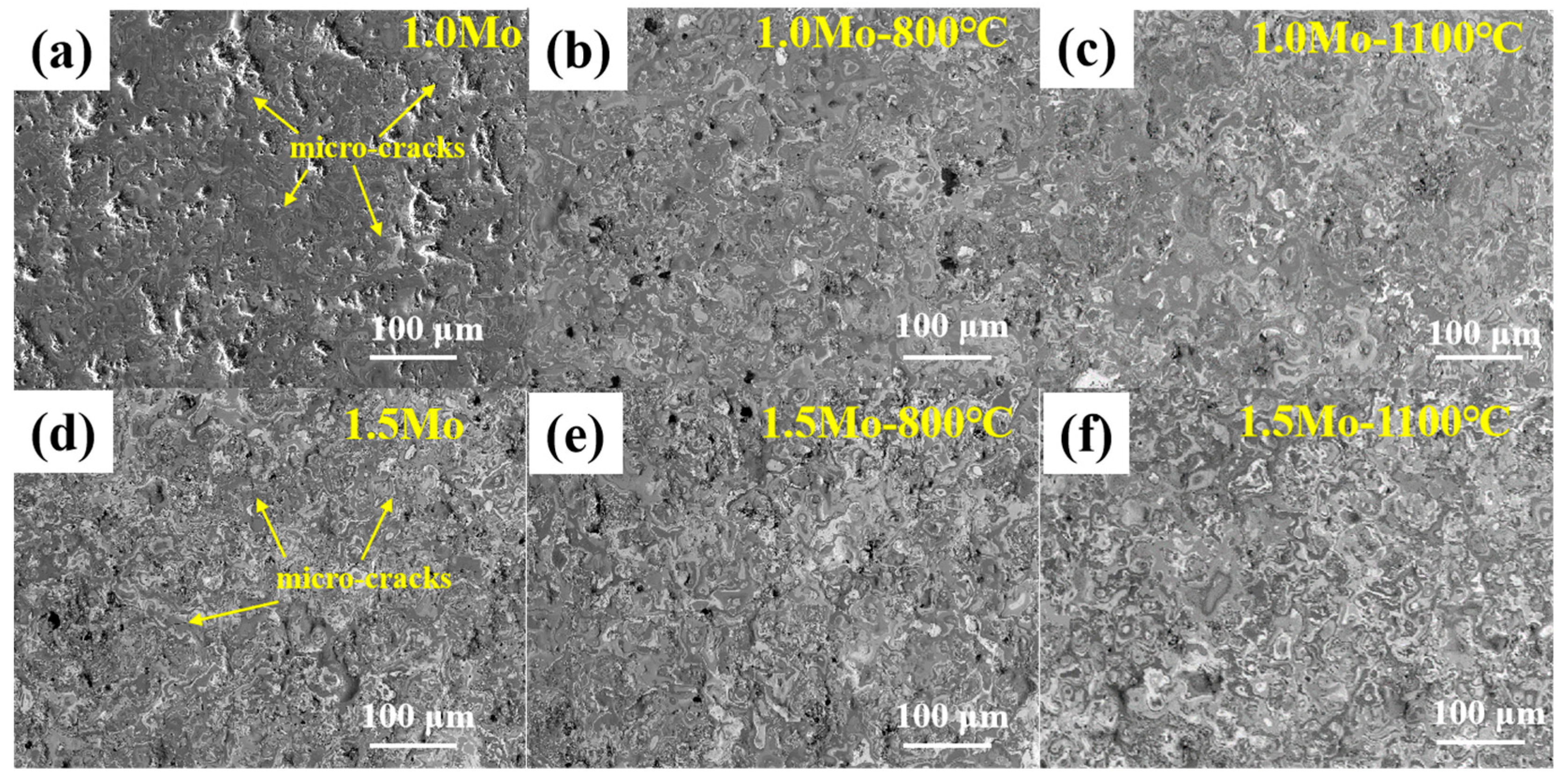
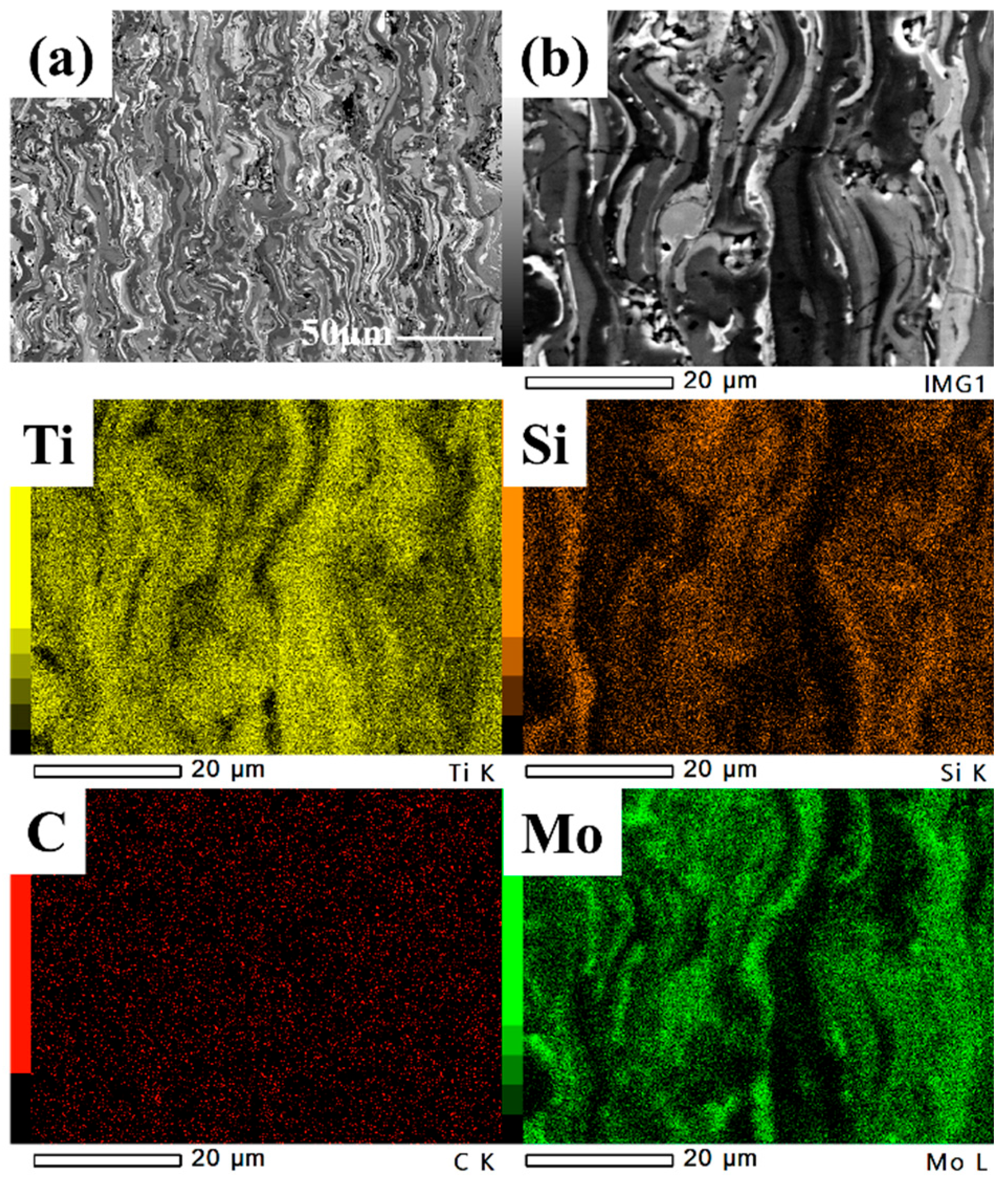
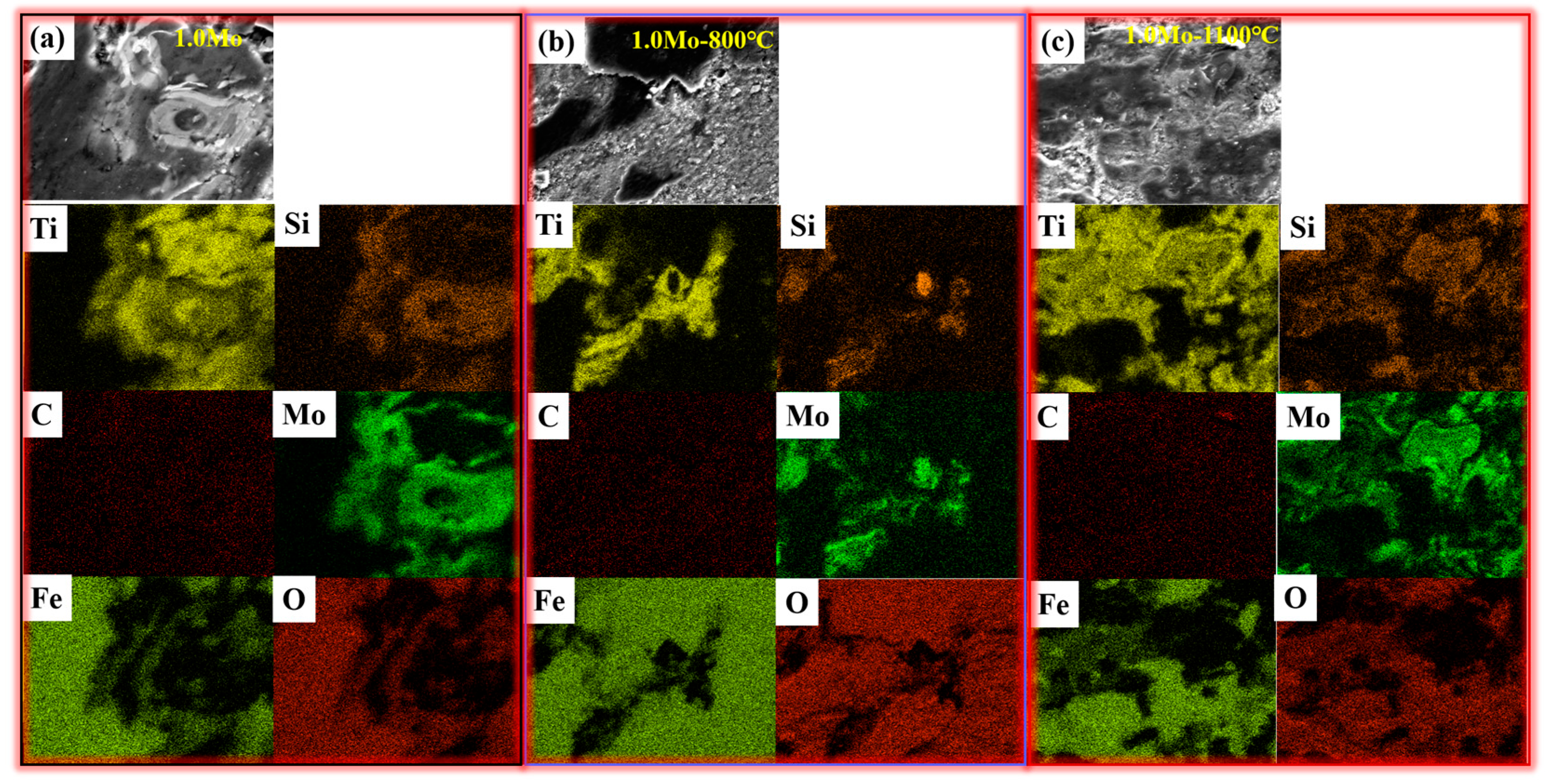
Ti–Si–C–Mo coatings are composed of TiC, Ti3SiC2, Ti5Si3 and residual graphite. After heat treatment at 800 °C and 1100 °C, the Ti3SiC2 and Mo5Si3 phases increased, and the Ti/Si/C/Mo elements diffused during the heat treatment process to make the microstructure more uniform.
(2)
The average microhardness of the Ti–Si–C–1.0Mo coating is HV 1394. After heat treatment at 800 °C and 1100 °C, the microhardness reduced to HV 1187 and HV 1171, respectively. The average microhardness of the Ti–Si–C–1.5Mo coating is HV 1400. After heat treatment at 800 °C and 1100 °C, it reduced to HV 1209 and HV 1145. This decrease in microhardness was mainly due to the heat treatment reducing the internal stress in the coating and increasing the formation of the soft phase, Ti3SiC2.
(3)
The fracture toughness of the Ti–Si–C–1.0Mo coating is 3.35 MPa·m1/2. After heat treatment at 800 °C and 1100°C, it decreased to 3.303 MPa·m1/2 and 3.227 MPa·m1/2. The fracture toughness of the Ti–Si–C–1.5Mo coating was 2.93 MPa·m1/2. After heat treatment at 800 °C and 1100 °C, it increased to 3.362 MPa·m1/2 and 3.413 MPa·m1/2, respectively.
(4)
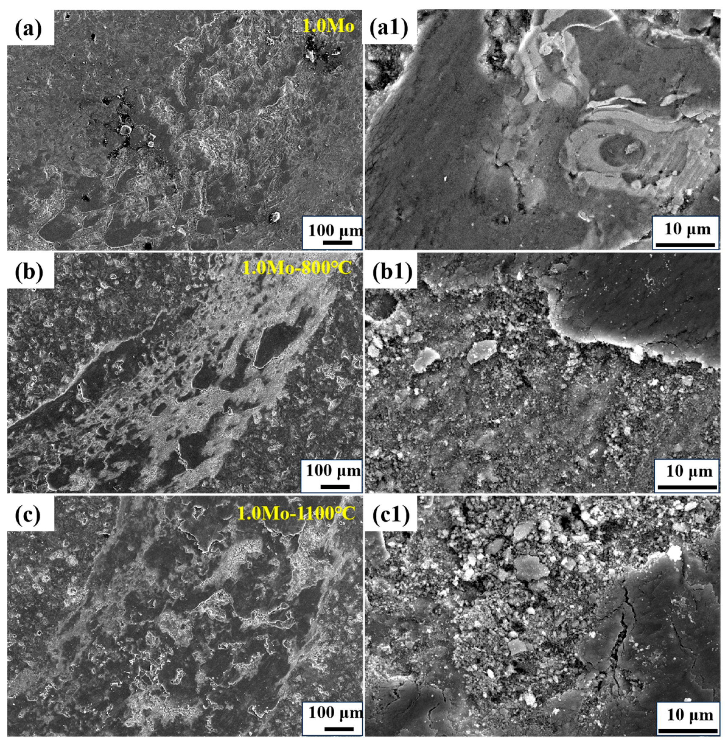
The friction coefficient of Ti–Si–C–1.0/1.5Mo coatings before and after heat treatment was 0.4~0.6, the wear weight loss of the coating after heat treatment was first reduced and then increased, and the minimum wear weight loss occurred after heat treatment at 800 °C.

Author Contributions

Resources: J.H. and J.F.; supervision: J.H.; project administration: J.H.; methodology: J.L. and J.F.; investigation: J.L. and J.F.; data curation: J.L.; writing-original graft: J.H. and J.L.; software: H.Z.; writing-review & editing: H.Z.; funding acquisition: H.Z.; review: Y.Q.; revision: H.Z. and Y.Q. All authors have read and agreed to the published version of the manuscript.

Funding

This work was supported by the National Natural Science Foundation of China (grant number 52102064; 51872073). This work was supported by the Natural Science Foundation of Hebei Province (grant number E2022202054).

Institutional Review Board Statement

Not applicable.

Informed Consent Statement

Not applicable.

Data Availability Statement

The data used to support the findings of this study are available from the corresponding author upon request.

Conflicts of Interest

The authors declare no conflicts of interest.

References

  1. Podgornik, B.; Sedlaček, M.; Batič, B.; Čekada, M. High temperature friction and galling properties of nanolayered (Cr,V)N coatings and effect of V content. Surf. Coat. Technol. 2023, 465, 129594. [Google Scholar] [CrossRef]
  2. Liu, Q.; Huang, S.; He, A. Composite ceramics thermal barrier coatings of yttria stabilized zirconia for aero-engines. J. Mater. Sci. Technol. 2019, 35, 2814–2823. [Google Scholar] [CrossRef]
  3. Shi, P.; Sun, H.; Yi, G.; Wang, W.; Wan, S.; Yu, Y.; Wang, Q. Tribological behavior and mechanical properties of thermal sprayed TiO2–ZnO and TiOx ceramic coatings. Ceram. Int. 2023, 49, 18662–18670. [Google Scholar] [CrossRef]
  4. Soković, M.; Mikuła, J.; Dobrzański, L.A.; Kopač, J.; Koseč, L.; Madejski, J.; Panjan, P.; Piech, A. Cutting properties of the Al2O3+SiC(w) based tool ceramic reinforced with the PVD and CVD wear resistant coatings. J. Mater. Process. Technol. 2005, 164–165, 924–929. [Google Scholar] [CrossRef]
  5. Zhang, Q.; Zhang, X.; Ma, Z.; Liu, L.; Liu, Y. Investigation of the oxidation of plasma sprayed silicon coating. Mater. Chem. Phys. 2022, 280, 125762. [Google Scholar] [CrossRef]
  6. Wang, Q.; Chen, F.Q.; Zhang, L.; Li, J.D.; Zhang, J.W. Microstructure evolution and high temperature corrosion behavior of FeCrBSi coatings prepared by laser cladding. Ceram. Int. 2020, 46, 17233–17242. [Google Scholar] [CrossRef]
  7. Liu, D.T.; Kong, D.J. Microstructure and electrochemical performance of plasma sprayed Fe45Mn35Co10Cr10 high−entropy alloy coating in different corrosive solutions. Intermetallics 2024, 165, 108154. [Google Scholar]
  8. Liu, G.; Wang, D.; Xing, Y.; Zhong, X.; Pan, W. Copper bonding silicon nitride substrate using atmosphere plasma spray. J. Eur. Ceram. Soc. 2023, 43, 3981–3987. [Google Scholar] [CrossRef]
  9. Zhao, P.; Zhu, J.; Yang, K.; Li, M.; Shao, G.; Lu, H.; Ma, Z.; Wang, H.; He, J. Outstanding wear resistance of plasma sprayed high-entropy monoboride composite coating by inducing phase structural cooperative mechanism. Appl. Surf. Sci. 2023, 616, 156516. [Google Scholar] [CrossRef]
  10. Wang, Y.; Huang, W.; Fan, X.; Zhang, J.; Mao, W. Microstructure and mechanical properties of plasma-sprayed LaMgA111O19 thick ceramic coatings. Ceram. Int. 2021, 47, 22435–22446. [Google Scholar] [CrossRef]
  11. Hashemi, S.M.; Parvin, N.; Valefi, Z.; Alishahi, M. Comparative study on tribological and corrosion protection properties of plasma sprayed Cr2O3-YSZ-SiC ceramic coatings. Ceram. Int. 2019, 45, 21108–21119. [Google Scholar] [CrossRef]
  12. Sun, X.; Huang, J.; Ye, Z.; Yang, J.; Chen, S.; Zhao, X. Study on microstructure evolution and reaction mechanism of in-flight Ti–Si–C agglomerates during reactive plasma spraying using in situ water quenching. Ceram. Int. 2022, 48, 18866–18875. [Google Scholar] [CrossRef]
  13. Chu, Z.; Wei, F.; Zheng, X.; Zhang, C.; Yang, Y. Microstructure and properties of TiN/Fe-based amorphous composite coatings fabricated by reactive plasma spraying. J. Alloys Compd. 2019, 785, 206–213. [Google Scholar] [CrossRef]
  14. Tan, Z.; Luo, C.; Zhu, W.; Yang, L.; Zhou, Y.; Wu, Q. Reactive plasma spraying of supersaturated tungsten super-hard Ta-Hf-W-C solid solution coating. J. Eur. Ceram. Soc. 2021, 41, 6772–6777. [Google Scholar] [CrossRef]
  15. Wu, L.; Zhang, K.; Zhou, Z.; Wang, G.; Zhang, X. Enhanced multi-scale nanomechanical deformation behavior in reactive plasma sprayed Fe-based amorphous/TiNx composite coating. J. Alloys Compd. 2023, 960, 171023. [Google Scholar] [CrossRef]
  16. Shao, Y.X.; Yang, Y.; Li, K.R.; Zhao, C.C.; Wang, Y.W.; Wang, X.Y. Reactive synthesis of ZrC-ZrSi2 composite coating by atmospheric plasma spraying. Surf. Coat. Technol. 2022, 450, 128976. [Google Scholar] [CrossRef]
  17. Sun, X.; Li, W.; Huang, J.; Yang, J.; Chen, S.; Zhao, X. Microstructure and properties of in-situ Ti5Si3-TiC composite coatings by reactive plasma spraying. Appl. Surf. Sci. 2020, 508, 145264. [Google Scholar] [CrossRef]
  18. Sun, X.; Li, W.; Huang, J.; Ye, Z.; Yang, J.; Chen, S.; Zhao, X. Effect of Si content on the microstructure and properties of Ti–Si–C composite coatings prepared by reactive plasma spraying. Ceram. Int. 2021, 47, 24438–24452. [Google Scholar] [CrossRef]
  19. Wang, X.-L.; Shao, Y.-X.; Guo, M.-Y.; Yang, Y.; Ma, Y.-D.; Cui, Y.-H.; Sun, W.-W.; Dong, Y.-C.; Yan, D.-R. Comparison of plasma sprayed NbB2-NbC coatings obtained by ex-situ and in-situ approaches. J. Eur. Ceram. Soc. 2021, 41, 5088–5099. [Google Scholar] [CrossRef]
  20. Cui, Y.-H.; Zhang, Q.; Shao, Y.-X.; Yang, Y.; Ma, Y.-D.; Sun, W.-W.; Wang, Y.-W.; Wang, X.-Y.; Dong, Y.-C. Microstructure and properties of in-situ ZrB2-ZrC composite coatings by plasma spraying. Surf. Coat. Technol. 2021, 409, 126846. [Google Scholar] [CrossRef]
  21. Wang, Y.-W.; Sun, X.-W.; Wang, L.; Yang, Y.; Ren, X.-X.; Ma, Y.-D.; Cui, Y.-H.; Sun, W.-W.; Wang, X.-Y.; Dong, Y.-C. Microstructure and properties of CrB2-Cr3C2 composite coatings prepared by plasma spraying. Surf. Coat. Technol. 2021, 425, 127693. [Google Scholar] [CrossRef]
  22. Tong, G.; Yu, L. Effect of Heat Treatment and Passivation on Corrosion Behavior of Electroless Ni-P Coating on 20# Steel in Simulated Soil Solution. Int. J. Electrochem. Sci. 2022, 17, 221247. [Google Scholar]
  23. Dong, H.; Guo, P.-F.; Han, Y.; Bai, R.-X.; Yang, Z.-C.; Zhang, S.-Q. Enhanced corrosion resistance of high speed laser-cladded Ni/316L alloy coating by heat treatment. J. Mater. Res. Technol. 2023, 24, 952–962. [Google Scholar] [CrossRef]
  24. Ghadami, F.; Sohi, M.H.; Ghadami, S. Effect of bond coat and post-heat treatment on the adhesion of air plasma sprayed WC-Co coatings. Surf. Coat. Technol. 2015, 261, 289–294. [Google Scholar] [CrossRef]
  25. Varis, T.; Lagerbom, J.; Suhonen, T.; Raami, L.; Terho, S.; Laurila, J.; Peura, P.; Vuoristo, P. Effect of heat treatments on the wear resistance of HVAF and HVOF sprayed tool steel coatings. Surf. Coat. Technol. 2023, 462, 129508. [Google Scholar] [CrossRef]
  26. Zhao, L.; Zhang, F.; Wang, L.; Yan, S.; He, J.; Yin, F. Effects of post-annealing on microstructure and mechanical properties of plasma sprayed Ti-Si-C composite coatings with Al addition. Surf. Coat. Technol. 2021, 416, 127164. [Google Scholar] [CrossRef]
  27. Zhao, H.; Hu, L.; Li, C.; Jiao, Q.; He, J.; Qin, Y.; Yin, F. Influence of metallic Cr addition on the phase structure and mechanical properties of plasma-sprayed Ti–Si–C coatings. Ceram. Int. 2021, 47, 17570–17579. [Google Scholar] [CrossRef]
  28. Li, S.; Fang, H.; Jiao, Q.; He, J.; Zhao, H.; Qin, Y.; Yin, F. Evolution of microstructure and mechanical performance of plasma-sprayed Ti–Cr–Si–C coatings annealed at 800 °C and 1100 °C. Vacuum 2022, 196, 110781. [Google Scholar] [CrossRef]
  29. Forn, A.; Picas, J.A.; Simón, M.J. Mechanical and tribological properties of Al–Si–Mo plasma-sprayed coatings. J. Mater. Process. Technol. 2003, 143–144, 52–57. [Google Scholar] [CrossRef]
  30. Jiao, Q.; Guo, F.; Li, C.; Zheng, G.; He, J.; Zhao, H.; Qin, Y.; Yin, F. Effects of Mo addition on tribological performance of plasma-sprayed Ti–Si–C coatings. Ceram. Int. 2020, 46, 12948–12954. [Google Scholar] [CrossRef]
  31. Yang, Y.; Wang, Y.; Tian, W.; Yan, D.-R.; Zhang, J.-X.; Wang, L. Influence of composite powders’ microstructure on the microstructure and properties of Al2O3–TiO2 coatings fabricated by plasma spraying. Mater. Des. 2015, 65, 814–822. [Google Scholar] [CrossRef]
  32. Li, W.; Yang, Y.; Liang, H.E.; Zhang, X.; Wang, Y.W.; Gou, J.F. Ablation resistance and mechanism of niobium carbide coatings fabricated by plasma spraying. Surf. Coat. Technol. 2023, 472, 129934. [Google Scholar] [CrossRef]
Figure 1. XRD pattern of Ti–Si–C–1.0/1.5Mo coating before and after heat treatment. (a) 1.0Mo; (b) 1.5Mo.
Coatings 14 00109 g001
Figure 2. Surface morphology of Ti–Si–C–1.0/1.5Mo coatings before and after being heated at 800 °C and 1100 °C. (a) 1.0Mo; (b) 1.0Mo–800 °C; (c) 1.0Mo–1100 °C; (d) 1.5Mo; (e) 1.5Mo–800 °C; (f) 1.5Mo–1100 °C.
Coatings 14 00109 g002
Figure 3. Surface EPMA analysis of Ti–Si–C–1.0 (ac)/1.5Mo (df) coatings before and after being heated at 800 °C and 1100 °C.
Coatings 14 00109 g003
Figure 4. Cross-sectional morphology and EDS element distribution of Ti–Si–C–1.0Mo coating after being heated at 1100 °C: (a) cross-sectional image; (b) EDS area and element distribution.
Coatings 14 00109 g004
Figure 5. Microhardness (a) and fracture toughness (b) of heated Ti–Si–C–1.0/1.5Mo coatings.
Coatings 14 00109 g005
Figure 6. Friction coefficient and wear weight loss of heated Ti–Si–C–1.0/1.5Mo coatings.
Coatings 14 00109 g006
Figure 7. Wear track image of heated Ti–Si–C–1.0Mo coating: (a)1.0Mo, (b) 1.0Mo–800 °C, and (c) 1.0Mo–1100 °C; (a1) enlarged view of (a), (b1) enlarged view of (b), and (c1) enlarged view of (c).
Coatings 14 00109 g007
Figure 8. Distribution of EDS elements in the wear track of the heated Ti–Si–C–1.0Mo coating. (a) 1.0Mo; (b) 1.0Mo–800 °C; (c) 1.0Mo–1100 °C.
Coatings 14 00109 g008
Figure 9. Wear track morphology of Ti–Si–C–1.5Mo coating after being heated at 800 °C and 1100 °C: (a) 1.5Mo, (b) 1.5Mo–800 °C, and (c) 1.5Mo–1100 °C; (a1) enlarged view of (a), (b1) enlarged view of (b), and (c1) enlarged view of (c).
Coatings 14 00109 g009
Figure 10. Distribution of EDS elements in Ti–Si–C–1.5Mo coating’s wear tracks after being heated at 800 °C and 1100 °C. (a) 1.5Mo; (b) 1.5Mo–800 °C; (c) 1.5Mo–1100 °C.
Coatings 14 00109 g010
Disclaimer/Publisher’s Note: The statements, opinions and data contained in all publications are solely those of the individual author(s) and contributor(s) and not of MDPI and/or the editor(s). MDPI and/or the editor(s) disclaim responsibility for any injury to people or property resulting from any ideas, methods, instructions or products referred to in the content.

