Abstract
Nitrile butadiene rubber (NBR) latex exhibits excellent tensile properties, chemical resistance, and thermal stability in applications such as gloves and safety shoes due to vulcanization. In this research work, attempts have been made to manipulate the vulcanization to produce thin and compact elastomeric NBR coating on myristic acid (MA) phase change material (PCM) to produce shape-stabilized PCM. The proposal for the use of latex-based elastomeric coating for PCM has been rarely considered in the literature due to a lack of understanding of the crosslink of elastomers. Thus, in this research, the effects of sulfur formulation on the coating performance of NBR on the PCM in terms of latent heat and thermal stability were determined. Leakage analysis indicates that the MA pellet coated with 0.5 phr of sulfur-cured NBR layer (MA/NBR-0.5) successfully eliminates the leakage issue. A tensile analysis revealed that a durable PCM coating layer must possess a combination of the following criteria: high tensile strength, ductility, and flexibility. Fourier transform infrared analysis (FTIR) and electron microscopy images showed the formation of thin, compact, and continuous NBR coating when 0.5 phr of sulfur was used. The further increment of sulfur loading between 1.0 and 1.5 phr causes the formation of defects on the coating layers, while non-vulcanized NBR layers seem to be very weak to withstand the phase-change process. The recorded latent heat values of melting and freezing of MA/NBR-0.5 are 142.30 ± 1.38 and 139.47 ± 1.23 J/g, respectively. The latent heat of the shape-stabilized MA/NBR-0.5 PCM is reduced by 32.24% from the pure MA latent heat density. This reduction is significantly lower than the reported latent heat reduction in shape-stabilized PCMs in other works. The thermal cycle test highlights the durability of the coated PCMs by withstanding up to 1000 thermal cycles (2.7 years) with less than 2% changes in latent heat value. Cooling performance test on photovoltaic (PV) module shows that the fabricated shape-stabilized PCM could reduce the temperature of the PV module up to 17 °C and increase the voltage generation by 7.92%. Actual performance analysis of shape-stabilized PCMs on the cooling of the PV module has been rarely reported and could be considered a strength of this work.
1. Introduction
Power generation by a photovoltaic (PV) module is highly influenced by temperature. Typical commercial silicon-based cells convert only 10–20% of the incident light into electricity and the rest is transformed into heat, which causes a rise in the temperature of the PV module up to 70 °C [1]. This elevated operating temperature reduces the solar-to-electrical conversion efficiency of the PV module. To enhance the efficiency of the PV module, it is important to keep the operating temperature as low as possible, preferably at the level of the so-called standard test conditions (STC) or 25 °C with 1000 W/m2 irradiation [2,3,4]. The PV cells will also exhibit long-term degradation if they are exposed to higher temperatures for a long duration, reducing their lifespan rapidly [5,6,7].
Active and passive cooling technologies could be applied to reduce the temperature of PV modules. The cooling technologies chosen should be reliable, easy to operate, and efficient in nature. Among the most studied cooling systems are heat pipe cooling, hydraulic water cooling, jet impingement cooling, liquid immersion cooling, micro-channel heat sink cooling, and thermo-photovoltaic system [8]. In a more recent study by Ahmad et al., the application of cooling PV modules using mist or fog water cooling systems resulted in a 27.01% reduction in maximum PV module temperature and a 16.66% increment in power generation, as reported in [9]. The cooling of PV modules using a thermoelectric system shows a reduction in temperature by 12.23 °C, which then increases the electrical efficiency by 5.07%. The levelized cost of electricity (LCE) is reduced to 0.410 USD/kWh from 0.414 USD/kWh for PV modules with a thermoelectric cooling system [10]. The cooling of PV using fanless CPU heat pipes in real weather conditions in Russia showed a temperature reduction of 6.72 °C with an increment of electrical efficiency of 2.98%. LCE increases in the range from 0.205–0.698 USD/kWh for non-cooled systems to 0.277–0.964 USD/kWh for PV modules with fanless CPU heat pipes [11]. These results prove the economic benefits of cooling PV modules.
Most of these active cooling systems based on air-to-water heat pumps or fans are needed for maintaining fluid circulation. These pumps or fans require a continuous power supply. For instance, in research carried out by Kazem et al., water is circulated using a pump in web-, direct-, and spiral-type flow. The spiral flow system showed the highest reduction in temperature and the highest increment of electrical efficiency [12]. Thus, the following question arises: If the active cooling system can support itself, how much net power could be generated by PV after some power is consumed for cooling? [3]. For example, when cooling through the water-spraying technique, an increase in PV electrical power generation efficiency by approximately 9–12% could be observed but the amount of water used was 30–50 L/min, with the power requirement of pump recorded as 90–135 W [13,14]. In a study by Mah et al., the application of the water-cooling system for the PV module at a water flow rate of 6 L/min could increase the net energy gain by 15%. The energy gained by PV with a cooling system was 0.128 kWh and the consumption of energy by the water circulation pump was 0.057 kWh [15]. Moreover, in the active cooling system, an additional mechanical assembly which requires piping and fitting is needed.
On the other hand, passive cooling methods using phase change materials (PCMs) are reported to increase the efficiency of PV by around 15% without additional power consumption [16]. The PCM cooling system shows higher heat transfer compared to both forced air circulation and water circulation, higher heat absorption due to latent heat, isothermal nature of heat removal, no noise, no electricity consumption, and no demand for heat delivery [3]. The capital cost for integrating PCM into the rear part of PV is also cheaper and the assembly is simple since in most cases it only requires a container to hold the PCM to the PV panel [17]. Recently, many attempts have been made to incorporate nano-enhanced PCM into PV modules to improve the cooling effect. In an experimental work carried out in Bangi, Malaysia to cool down PV modules using nano-enhanced paraffin and nanofluids, the installation of the PCM tank on the module increases the electrical efficiency by 13.7% [18]. Abdelrazik et al. reported that the usage of paraffin wax PCM with 10 wt% graphene nanoplatelets as the cooling system increased electrical efficiency by 22% [19]. In a similar research, usage of paraffin wax filled with 0.01 wt% nano graphite improved the power output by more than 20% [19].
Organic PCMs are preferred over inorganic PCMs since they exhibit stable phase change temperatures without phase segregation and no super cooling effect. In this study, a fatty acid is chosen since it exhibits high latent heat (160–220 kJ/kg) and a suitable melting temperature, is easily available, and is economical [20]. However, the practical uses of organic PCMs in PV cooling are still limited due to the high volume change in PCMs during the phase change transition and leakage problem. These two problems will cause fire safety issues, pressure build up, and corrosion and disturb the PV wiring [21]. One method to solve the leakage and volume change problem of organic PCM is producing form-stable PCMs. In previous research, this is carried out by blending PCMs with other polymers or coating the PCMs. For instance, paraffin wax PCM was blended with high-density polyethylene (HDPE) and laminated with aluminum foil to eliminate leakage problems [22]. However, in a previous example of research, a large reduction in latent heat was observed during the formation of form-stable PCMs. Tang et al. [23] reported a decrease in latent heat for palmitic acid coated with high-density polyethylene/graphene platelet form-stable PCMs from 221 J/g to 157 J/g. In another research by Peizhao et al. [24], the latent heat of melting for paraffin reduced from 220 J/g to 89 J/g when coated with nanoclay. A similar reduction in latent heat was observed by Tian et al. [25] when paraffin is coated with ethylene vinyl alcohol/expanded graphite.
The reduction in latent heat is caused by a large mass fraction of coating material applied in the PCM system [26]. Sarac et al. coated organic coconut oil PCM with two types of coating: polymethyl methacrylate (PMMA) and melamine formaldehyde (MF). The latent heat of the organic coconut oil reduces from 107.5 J/g to 39.1 and 81.9 J/g for form-stable PCMs coated with PMMA and MF, respectively. The larger reduction in latent heat value for samples coated with PMMA contributed by a thicker coating layer of PMMA compared with the MF coating layer [27]. The in situ polymerization of polymeric-based coatings such as MF and polyurethane coatings on PCMs is usually carried out by a series of chemical processes. In these processes, it was complicated to control the thickness of the coating compared to the dip coating and curing method applied in the current work [28,29]. Moreover, the coating was yielded from the in situ polymerization technique influenced by the surfactant type [30]. A poor understanding of coating material chemistry has led to the application of the repeated coating cycle which has eliminated leakage and reduced volume expansion but also dramatically reduced the latent heat.
Thus, in this research work, it is proposed to develop a thin, strong, and compact coating on the surface of fatty-acid PCM using crosslinked NBR latex. In previously reported works, the encapsulation of PCMs was carried out using titania [31], acacia gum [32], silicon oxide [33], polyurethane [34], polymethyl methacrylate (PMMA) [35], MF [36], and high-density polyethylene (HDPE) [37]. Coating PCMs using crosslinked latex has never been reported before in the literature to the best of our knowledge. NBR latex-based coating was chosen because NBR is famously used for applications such as latex gloves due to its elasticity, strength, and chemical resistance properties [38,39]. The main objective of this particular study is to determine the optimum loading of sulfur in the crosslinking formulation of NBR to yield a good coating with no leakage and high latent heat. The expectation is that with the right manipulation of NBR formulation and crosslink parameters a thin, strong, and compact coating on PCM could be formed. This will decrease the need for a repeated coating cycle, reduce the mass fraction of coating material, and maintain high latent heat with the elimination of leakage and a reduction in volume expansion.
2. Materials and Methods
2.1. Materials
Myristic acid with purity ≥ 98% was obtained from R&M Chemicals Sdn. Bhd., Semenyih, Malaysia. Nitrile butadiene rubber (NBR) with a total solid content of 61% was purchased from Synthomer Sdn. Bhd., Kluang, Johore, Malaysia. Bridge Field Resources Sdn. Bhd, Selangor, Malaysia, supplied the sulfur crosslink agent, zinc oxide (ZnO) activator, zinc 2-mercaptobenzothiazole (ZMBT) and zinc diethyldithiocarbamate (ZDEC) accelerators, and potassium hydroxide (KOH). Sulfur, ZnO, ZMBTm and ZDEC were in powder form and the chemicals were prepared into a slurry with a total solid content of 45% for each, using an overhead mechanical stirrer model IKA RW 20 Digital. A weighed amount of each powder was mixed with water and stirred continuously for 3 h at a stirring speed of 500 rpm using the stirrer.
2.2. Compounding of NBR Coating Emulsion
NBR latex with the sulfur formulation of 0.5, 1.0, and 1.5 phr was prepared through the latex compounding method with compounding ingredients as outlined in Table 1. An overhead mechanical stirrer model IKA Overhead Stirrers RW 20 Digital, Germany, was used for compounding. First, the overhead mechanical stirrer was immersed in NBR latex inside a beaker and the stirring speed was fixed at 200 rpm. Then, half the amount of KOH was added to the NBR latex, followed by ZMBT, ZDEC, ZnO, and sulfur in a slurry form. Leftover KOH was used to rinse out the remaining compounding ingredients from the beaker into NBR latex. The stirring speed of the overhead stirrer increased to 250 rpm and the stirring continued for another 30 min. These steps were repeated to compound NBR latex with the different sulfur formulations.

Table 1.
Compound formulation of NBR latex with different sulfur loadings.
2.3. Preparation of Coated MA PCMs
A total of 0.28 g of MA flakes was compressed into a pellet using a hydraulic presser model 12-ton E-Z PressTM at a pressure of 4000 kPa. Before the dip-coating process, the compounded NBR latex was degassed in a vacuum oven for 15 min to remove bubbles at ambient temperature. The MA pellets were dipped into NBR latex containing 0.5 phr (MA/NBR-0.5), 1.0 phr (MA/NBR-1.0), and 1.5 phr (MA/NBR-1.5) sulfur, respectively, at a fixed immersion time of 5 s with forceps. An MA pellet dipped in pure NBR without any compounding ingredients was also prepared. The MA/NBR samples were laid on a Teflon sheet and cured in a vacuum oven for 9 h at 45 °C. Cured MA/NBR pellets were naturally dried in a fume hood at a room temperature of 28 °C for a day. After drying the coating layer, the coating and drying process was repeated with the same pellet flipped upside down to ensure the front and back of the pellets were coated well and had similar coating thickness. The coating process is as shown in Figure 1.

Figure 1.
Dip coating method of MA PCMs. (a) Dip coating of MA PCM pellet with NBR latex, (b) drying of coated PCM on Teflon sheet.
2.4. Characterization of PCMs
2.4.1. Leakage Test
The leakage test method was adapted from the research carried out by Kee et al. [40]. Six blue litmus paper strips stuck onto a white background paper as shown in Figure 2. In the middle of the litmus papers, a standard circle with a diameter of 15 mm was drawn. MA/NBR pellet was positioned within the circle on the litmus papers and heated at 60 °C for an hour in the universal oven model UN 110, Memmert, GmbH + Co. KG, Schwabach, Germany, to ensure the MA was completely melted. After one hour, the samples were taken out and cooled to room temperature. One thermal cycle consists of one hour of heating in the oven and two hours of the natural cooling process. Leakage occurs when the blue litmus paper turns pink. Then, the leakage region of the MA/NBR pellet was measured using GIMP 2 and Image J software version 1.53t.
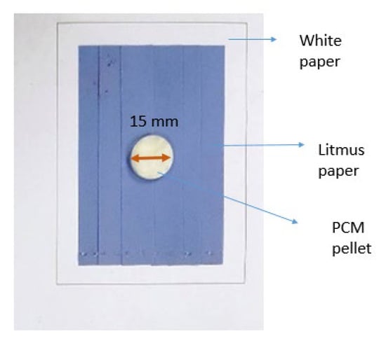
Figure 2.
Leakage test setup.
2.4.2. Crosslink Density Calculation
The crosslink density calculation was performed with the equilibrium swelling method. A total of 3.8 g of NBR latex was cast into a film using a Teflon mold. NBR polymer films with a dimension of 10 × 10 × 2 mm (l × w × t) were prepared and immersed in a beaker filled with 50 mL toluene. The beakers were kept in the dark for 7 days at 25 °C. The volume fraction and crosslink density of NBR were calculated using Equations (1) and (2), respectively [41]. The density of rubber specimens was determined by using a precision balance with a density-determining kit model Presica ES 320 A. Five tests were conducted for each NBR film with different sulfur formulations and the average volume fraction of rubber was calculated.
whereby
vr is the volume fraction of rubber;
w1 is the weight of a swollen sample;
w2 is the weight of a sample after drying at 60 °C to constant weight;
ρ1 is the density of the solvent (0.87 g/mol) [42];
ρ2 is the density of the nitrile rubber specimen.
whereby
V is the crosslink density;
vr is the volume fraction of rubber;
vs is the molar volume of solvent (toluene = 106.2 cm3/mol) [41];
x is the rubber-solvent interaction parameter (x = 0.435) [42].
2.4.3. Thermal Properties Analysis
The thermal properties of MA/NBR PCMs included the latent heat of melting and freezing. The melting and freezing temperatures were determined by using a differential scanning calorimetry (DSC) model DSC 1 Mettler Toledo TOPEM. The test was performed at temperatures ranging from 25 to 100 °C with a constant flow of nitrogen gas at a flow rate of 20 mL/min. The heating rate was set at 5 °C/min and the test was conducted in accordance with ASTM-D3418 standard. Five samples were tested for each sulfur loading and average values were reported. The reduction in latent heat of the coated PCMs was calculated using Equation (3).
whereby LMA is the latent heat of pure MA pellet, LCoated PCM is the latent heat of coated PCMs.
The thermal reliability of the PCMs was determined using an in-house thermal cycling system designed by the University of Malaya [43]. The thermal cycle system was designed to conduct testing from 30 to 80 °C. For each thermal cycle, samples were heated to 80 °C followed by cooling to room temperature. In this work, 1000 thermal cycles, which are equivalent to 2.7 years, were performed with each cycle representing a day of heat gain and heat release. The samples were subjected to DSC analysis before and after 1000 thermal cycles to calculate the latent heat reduction. Five samples were used for each sulfur loading and the average value of latent heat was taken. The reduction in latent heat before and after the thermal cyclic test was calculated using Equation (4).
whereby LBefore thermal cycle is the latent heat of PCMs before the thermal cycle test and LAfter thermal cycle is the latent heat after the thermal cycle test.
2.4.4. Tensile Test
The tensile test was carried out using a lightweight tensile tester model Tinius Olsen H10KS-0748. The test was performed in accordance with the ASTM-D638 standard to determine the ultimate tensile strength (UTS), Young’s modulus, and elongation at a break of the NBR films with different concentrations of sulfur. The test was performed with a 500 N load cell and 500 mm/min crosshead speed. Six samples were tested for each sulfur concentration of NBR and the average value was calculated.
2.4.5. Chemical Functionality of PCM Pellets
The Fourier Transform Infrared Spectroscopy (FTIR) model and the Perkin Elmer Spectroscopy 2000 FT-IR Spectrophotometer were used to determine the spectrum of pure MA flakes. The spectra of pure NBR film and MA/NBR pellets were determined with the Fourier Transform Infrared Spectroscopy-Attenuated Total Reflection (FTIR-ATR) model and the Perkin Elmer Spectrum Two FTIR Spectrometer. Both analyses were performed in the wavelength range from 4000 to 400 cm−1 with 32 scans. FTIR-ATR was used for the MA/NBR pellets because it can analyze the PCMs in their natural states without destroying the NBR coating layer.
2.4.6. Morphology of Coatings
The surface and cross-section morphology of pure MA/NBR pellets with different sulfur formulations were observed via the Field Emission Scanning Electron Microscopy (FESEM) model JEOL JSM 6701F. The surface and cross-section morphology of PCMs were viewed with the magnification of 5000× and 250×, respectively. The cross-section samples were prepared by cryogenic fracturing of PCM pellets. The thickness of the coating layer was measured by choosing five pellets (five points on each pellet) for each sulfur formulation of NBR using Image J software and the average thickness was calculated.
2.4.7. Photovoltaic Temperature Reduction and Power Generation
Eight PCM tablets weighing 65 g were prepared using teflon molds. MA was pressed into the molds to produce PCM tablets. The tablets were then coated with NBR-0.5 phr sulfur and cured. The PCM tablets were then attached to the rear part of the PV module. A detailed experimental setup to measure temperature reduction and power generation in the PV panel is explained in our previously published work [44]. The main objective of this experiment is to validate the performance of the prepared PCMs on an actual PV module. Thermocouples are fixed on a heated surface, the top surface of fin heat sink (FHS), and the fin of FHS. To measure the cooling effect, eight thermocouples were fixed to the surface and rear part of the PV panel. Data on PV cooling performances were collected from 10 a.m. to 3 p.m. every day for 30 sunny days in January and February 2023. The wind speed and relative humidity were recorded as 3 to 5 km/h and 80 to 81%, respectively. The setup for this test was installed on the rooftop of Block E, Faculty of Engineering and Green Technology, University Tunku Abdul Rahman Malaysia. Equation (5) was used to calculate the maximum power output.
where Pout is maximum power output, VOC is open circuit voltage, ISC is short circuit current, and FF is fill factor.
3. Results
3.1. Leakage Analysis
The leakage area percentages for PCMs are shown in Figure 3 and their details are tabulated in Table 2. The MA/NBR-0.5 pellet shows no leakage after 60 thermal cycles as the blue litmus paper remains unchanged in color and, thus, is suitable to be used in thermal energy storage applications as form-stable PCM. Meanwhile, for MA/NBR-1.0 and MA/NBR-1.5 pellets, the leakage area percentage increases with the increasing sulfur formulation.
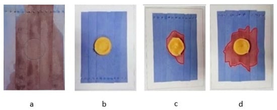
Figure 3.
Leakage comparison of (a) uncoated MA pellet; (b) MA/NBR-0.5; (c) MA/NBR-1.0; and (d) MA/NBR-1.5 pellet after 60 thermal cyclic processes.

Table 2.
Leakage area percentage of MA/NBR pellets with different sulfur formulations.
3.2. Crosslink Density Calculation
Table 3 tabulates the crosslink density of NBR films. The crosslink density of the film increases with increasing sulfur formulation during the vulcanization of NBR, which is in agreement with a previous study carried out by Lawandy and Halim [45].

Table 3.
Crosslink density of PCM with different sulfur formulation.
3.3. Tensile Properties of the Coating
In Figure 4a, the UTS of vulcanized NBR films increases when sulfur formulation increases because of the higher degree of crosslinking in between the NBR chains as indicated by crosslink density measurement. Figure 4b,c illustrate an increasing trend for Young’s modulus and a decreasing trend for elongation at break when sulfur formulation increases which corresponds to lower ductility and flexibility of the coating layer.
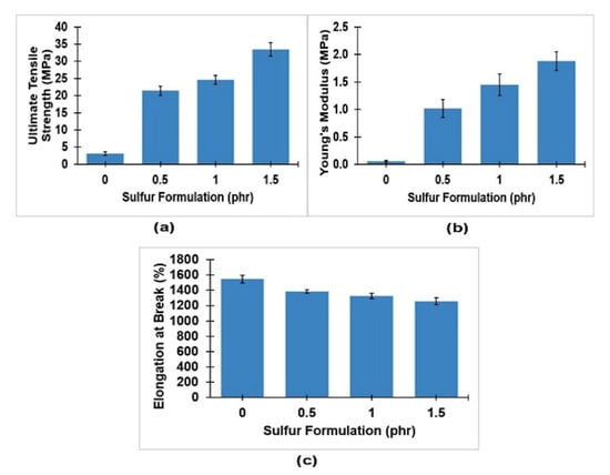
Figure 4.
(a) Ultimate tensile strength, (b) Young’s modulus, and (c) elongation at break of pure NBR and NBR films with different sulfur formulations.
3.4. Chemical Functionality of Coatings
The spectra of pure MA, pure NBR, and MA/NBR pellets are illustrated in Figure 5. Pure MA peaks were observed at 2841 cm−1 (asymmetrical stretching of -CH2), 1696 cm−1 (C=O peak), 1433 cm−1 (CH2 bend), 1290 cm−1 (C-H bending), and both 939 cm−1 and 720 cm−1 (-OH stretching peaks) [46,47].
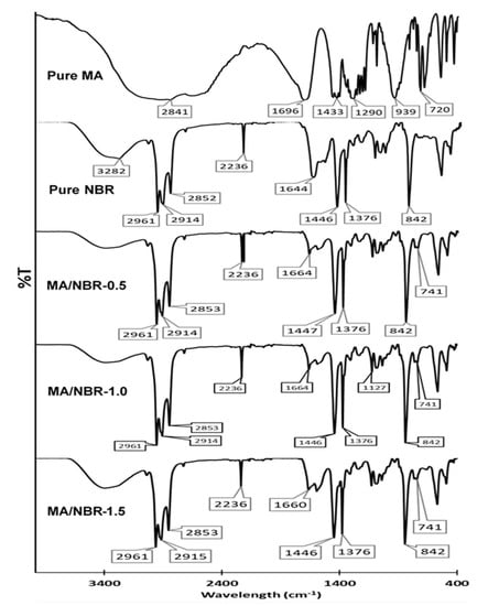
Figure 5.
FTIR spectra of pure MA, pure NBR, and MA/NBR pellets with different sulfur formulation.
Pure NBR shows O-H symmetric and N-H stretching vibration between a broad stretch of 3651 cm−1 and 3093 cm−1-C-H stretch at 2961 cm−1 [48], asymmetrical and symmetrical stretching vibration of methylene in the hydrocarbon backbone at the peak of 2914 cm−1 and 2852 cm−1 [49]. It also exhibits a C≡N bond at 2236 cm−1, C=C stretching at 1644 cm−1, -C-H bending at both 1446 and 1376 cm−1, and C=C bending at 842 cm−1 [50].
3.5. Surface and Cross-Section Morphology Analysis
Holes and microcracks were observed on the surface of pure NBR, MA/NBR-1.0, and MA/NBR-1.5 pellets as shown in Figure 6a,c,d. On the contrary, no cracks or holes were spotted on the FESEM image of the MA/NBR-0.5 pellet. This observation supports the leakage test results in Section 3.1 as to why the MA/NBR-0.5 pellet does not leak but others do. During the phase change process from solid to liquid, the liquid MA could leak out from the cracks and holes on the coating. The imperfect coating will not be able to contain the melted MA. In the FESEM image of MA/NBR-1.5 pellet, elemental sulfur particles were spotted on its surface [51]. Only a certain proportion of sulfur succeeded in crosslinking to the C=C double bond of the butadiene part in NBR and the other remains as excess. This leads to the formation of a less elastic coating and over-curing which results in a non-continuous coating structure with cracks. The representation of the cross-section surface morphology for MA/NBR pellets are displayed in Figure 7. On average, the thickness of coatings for MA/NBR-0, MA/NBR-0.5, MA/NBR-1.0 and MA/NBR-1.5 are 170.5 ± 2.3 μ, 158 ± 1.3 μ, 177.6 ± 2.2 μ and 186 ± 1.4 μ, respectively. A small gap was spotted between MA and the NBR coating layer for all the FESEM images. This describes that MA does not chemically react with the NBR coating layer, which was confirmed by the result from the FTIR analysis, as the spectra of PCMs do not contain functional groups that are present in MA. In the FESEM images of pure NBR, MA/NBR-0.5, MA/NBR-1.0, and MA/NBR-1.5 pellets, microcracks appeared on the surface of NBR coating layers (red box).
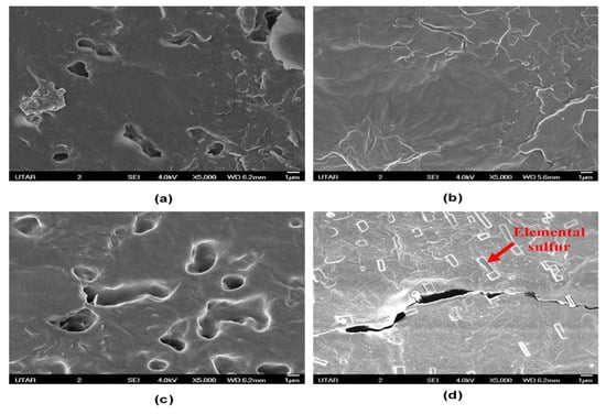
Figure 6.
FESEM surface morphology of (a) pure NBR; (b) MA/NBR-0.5; (c) MA/NBR-1.0; (d) MA/NBR-1.5 pellets with magnification of 5000×.
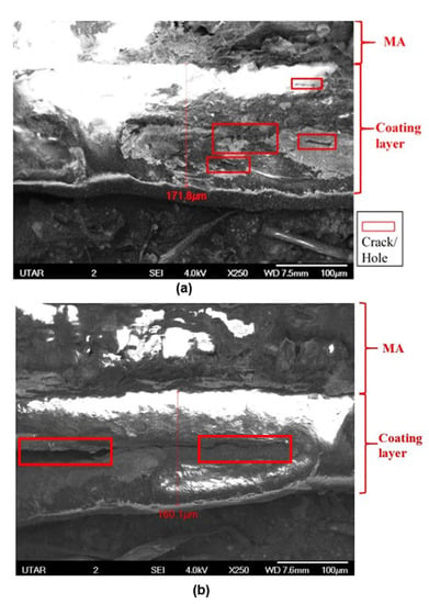
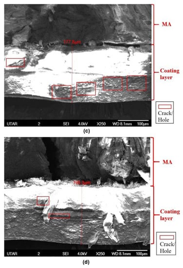
Figure 7.
FESEM cross-section morphology of (a) pure NBR; (b) MA/NBR-0.5; (c) MA/NBR-1.0; (d) MA/NBR-1.5 pellets with magnification of 250×.
3.6. Thermal Properties of Dip-Coated MA Pellet
Table 4 and Figure 8 show the latent heat of melting and freezing, melting point and freezing point of pure MA and MA/NBR pellets. Pure MA recorded the latent heat of melting and freezing at 210.02 ± 2.46 and 209.95 ± 2.38 J/g, respectively. The latent heat of melting and freezing for all MA/NBR pellets was lower than the pure MA and decreased with the increasing sulfur formulation. This is because pure MA was the sole content of the MA pellet, while MA/NBR pellets consist of MA and NBR coating layers. Only MA contributes to the latent heat of PCMs and if the weight fraction of MA in the pellet reduces, the latent heat will also reduce. As the coating layer thickness increases with an increasing sulfur formulation in NBR as shown in FESEM images of the MA/NBR pellets, the latent heat reduction will become more prominent. MA/NBR-0.5 pellet recorded latent heat of melting and freezing of 142.30 ± 1.38 and 139.47 ± 1.23 J/g, respectively, which was 32.24% latent heat reduction from the MA’s latent heat capacity.

Table 4.
Thermal properties of pure MA and MA/NBR pellets.
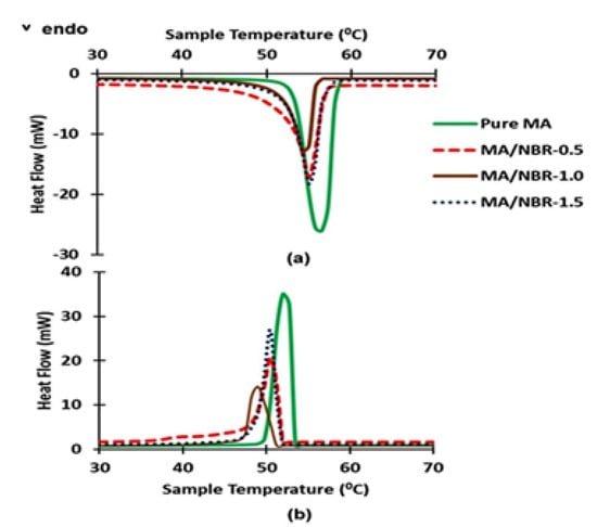
Figure 8.
(a) Heating curve and (b) cooling curve of pure MA and MA/NBR pellets.
The thermal reliability of MA/NBR pellets was analyzed by using DSC after being subjected to the 1000 thermal cycles test and their melting and freezing points were tabulated in Table 5. All MA/NBR pellets have variance in melting and freezing temperatures before and after the thermal cycle test. The percentage change of MA/NBR pellets’ melting and freezing point after the thermal cycle test were small and less than 3%.

Table 5.
Melting and freezing point of MA/NBR pellets before and after 1000 thermal cycles tests.
Table 6 displays the latent heat of melting and freezing of MA/NBR pellets before and after 1000 thermal cycle tests. For MA/NBR-0.5 pellet, latent heat of melting and freezing was reduced by 1.64 and 1.76%, respectively. The latent heat of melting of MA/NBR-1.0 and MA/NBR-1.5 pellets reduced by 8.73 and 21.37%, respectively while the latent heat of freezing decreased by 11.02 and 24.38%, respectively. DSC curves for MA/NBR pellets before and after thermal cycling tests were illustrated in Figure 9.

Table 6.
Latent heat of melting and freezing of MA/NBR pellets before and after 1000 thermal cycles tests.
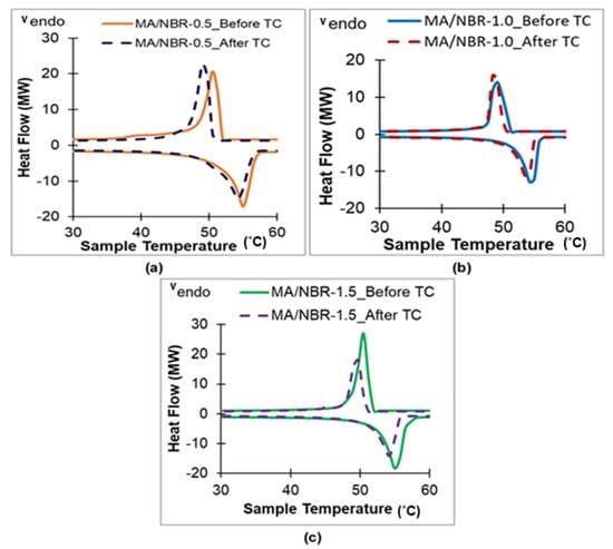
Figure 9.
DSC curves for (a) MA/NBR-0.5; (b) MA/NBR-1.0; and (c) MA/NBR-1.5 pellets before and after 1000 thermal cycle tests.
3.7. Effect of Coating Solution on the Performance of the Solar PV Module
The installation of the shape-stabilized PCM kept the temperature of the PV panel lower than the temperature of the reference panel. The recorded maximum temperature difference in Figure 10 is 17 °C. Vavr output by the reference panel and the PCM installed panel are recorded as 18.93 and 20.43 V, respectively, as shown in Figure 11. Vmax for the reference panel and PCM installed panel were 20.35 and 21.00 V, respectively.
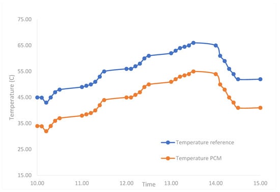
Figure 10.
Cooling effect of PCM on PV module.
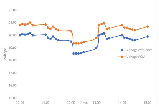
Figure 11.
Cooling effect of PCM on PV module for voltage generation.
4. Discussion
Bakhshandeh et al. highlighted the improvement of elastomer properties in terms of tensile strength, hardness, and modulus when a higher level of sulfur was introduced [52]. However, too much sulfur causes rubber coating to become less elastic and ductile, and hence increases the tendency of leakage when PCMs melt and experience volume change. The transition from the solid to liquid phase of MA PCMs during melting will cause pressure to build up from the inside of the PCM pellets to the coating layer. If the coating layer is not elastic and strong enough, the repeated solid–liquid and liquid–solid transitions of MA will form the pressure build-up cycle which causes breakage in the coating layer and lead to leakage of MA. Thus, it is vital to measure the degree of crosslink density of the coating layer to correlate with their physical properties such as tensile strength, modulus, and hardness [53]. The crosslink density measurement of NBR coating films proved that high crosslink density does not prevent leakage and an optimum crosslink density is required to withstand pressure build-up caused by volume expansion during phase change [54,55]. Samples with fewer crosslinks will be more elastic and deform upon the application of internal pressure.
Sulfur creates a three-dimensional crosslink network between the NBR chains and allows the NBR chains to be stretched without slipping past each other [56] and forms a strong coating to withstand volume change. Based on this theory, the NBR film with 1.5 phr sulfur (UTS = 33.430 ± 1.925 MPa) has the strongest tendency to prevent MA from leaking after being heated beyond its melting point. However, the leakage test shows that MA/NBR-1.0 and MA/NBR-1.5 have leakage signs while MA/NBR-0.5 pellet does not. This is because a good coating material must possess the combination of criteria of high tensile strength, ductility, and flexibility as such exhibited by MA/NBR-0.5 [57].
NBR coating layer with 1.0 and 1.5 phr sulfur was unable to withstand the volume change and internal pressure subjected by MA during the thermal cycle test. When the coating films are less elastic, they will form cracks and fail easily. MA/NBR-0.5 pellet with UTS of 21.433 ± 1.396 MPa, Young’s modulus of 1.018 ± 0.162 MPa, and elongation at break of 1386 ± 23.259% is more suitable for PCM coating application because no leakage is being observed up to 60 thermal cycles.
The formation of a good coating layer was validated through FTIR analysis and FESEM images. All MA/NBR pellets have similar FTIR spectra as NBR, which implies good coating coverage on the sample surface. An additional C-S bond at the peak of 741 cm−1 was observed in the spectra for MA/NBR pellets [58]. This confirms the occurrence of NBR sulfur vulcanization as the pure NBR spectrum does not contain C-S peak. The intensity of the C=C bond stretching at 1644 cm−1 for MA/NBR pellets was much lower as compared to the pure NBR. This is because the C=C bond of butadiene in NBR was used for the formation of the C-S bond.
FESEM images indicate the formation of defects in PCMs coated with pure NBR, MA/NBR-1.0, and MA/NBR-1.5. These defects become weak points to withstand the internal pressure of MA when the phase change occurs, which confirms the result obtained from the leakage test. The surface of pure NBR, MA/NBR-1.0, and MA/NBR-1.5 pellets was rougher and uneven as compared to the MA/NBR-0.5 pellet in which appears to be compact and smooth. The MA/NBR-0.5 pellet also has the thinnest coating layer (160.1 μm) as compared to pure NBR, MA/NBR-1.0, and MA/NBR-1.5 pellets. This is because the pure NBR coating layer was not cured at 40 °C and, water molecules might not fully evaporate from the NBR layer thus forming a thick coating layer. MA/NBR-1.0, and MA/NBR-1.5 pellets have a thicker coating layer because more sulfur content was introduced into the NBR solution for vulcanization. Therefore, more dry matter will remain on the MA pellet after its moisture removal. The thinner and more compact coating will result in higher latent heat storage capacity in the PCMs.
In this study, the reduction in latent heat of PCMs due to the introduction of coating is lower compared to the other researchers’ works whereby most of them encountered more than 50% latent heat reduction as shown in Table 7. Moreover, the MA/NBR-0.5 pellet’s latent heat storage capacity from the present work was much higher (142.30 ± 1.38 J/g) than the shape-stabilized PCM’s latent heat produced from previous studies listed in Table 7. Pure MA has a melting and freezing point of 56.16 and 52.27 °C, respectively. The melting and freezing points of MA/NBR pellets do not differ much from pure MA.

Table 7.
Comparison between current work and other researchers’ work on organic fatty acid shape-stabilized PCMs and their thermal properties.
Due to the high latent heat of melting and freezing of MA/NBR shape stabilized PCMs, the heat from the PV panel was transferred to the PCM by conduction [10]. More heat is continuously absorbed into the PCM from the PV panel surface, which then causes a continuous cooling effect on the PV panel. Cooling of the PV panel then yielded on higher voltage output. The temperature reduction in PV and power generation increment is comparable with previously reported results from the literature as shown in Table 8.

Table 8.
Comparison of thermal and electrical performances of PV modules in current work with others work from literature.
5. Conclusions
In this work, shape-stabilized PCM (MA/NBR) was successfully prepared by dip-coating of MA pellet in NBR latex containing sulfur and cured for 9 h at 45 °C. The leakage test revealed that the leakage area percentage of MA/NBR pellets increased with increasing sulfur addition into NBR latex. The tensile test shows MA/NBR pellets’ coating layer must possess combination criteria of good tensile strength, ductility, and flexibility to prevent leakage. The MA/NBR-0.5 pellet has a UTS of 21.433 ± 1.396 MPa, Young’s modulus of 1.018 ± 0.162 MPa, and elongation at a break of 1386 ± 23.259% respectively, which yielded strong and flexible coating to eliminate leakage. In the FTIR analysis, the presence of the C-S peak in vulcanized NBR layers at the wavelength of 741 cm−1 indicates the occurrence of the NBR vulcanization process. FESEM image displays no cracks and holes spotted on the MA/NBR pellet’s surface and cross-section morphology when 0.5 phr sulfur is used.
Shape-stabilized PCM with a coating layer thickness of 160.1 μm in the MA/NBR-0.5 pellet recorded the highest latent heat of melting and freezing compared to other coated samples due to the formation of a thin and compact coating layer. After the 1000-thermal-cycle tests, shape stabilized PCM’s latent heat of melting only reduced by 1.64% which indicates excellent reliability of the samples for 2.7 years. The cooling performance analysis on the PV module indicates a good cooling effect by the shape stabilized PCMs with a reduction in PV module temperature up to 17 °C and an increase in power generation by 5.54%. To further implement this PCM system for cooling PV, an effective PCM storage tank or container should be designed and studied in the future.
Author Contributions
Conceptualization, Y.M. and M.K.; methodology, Y.M. and F.K.A.; software, Y.M.; validation, Y.M., M.K. and F.K.A.; formal analysis, M.A.; investigation, F.K.A.; resources, Y.M.; data curation, Y.M.; writing—original draft preparation, Y.M. and M.K.; writing—review and editing, M.K. and Y.M.; visualization, M.K.; supervision, M.A.; project administration, F.K.A.; funding acquisition, F.K.A. All authors have read and agreed to the published version of the manuscript.
Funding
This research was funded by the Deanship of Scientific Research at University of Bisha, grant number UB-GRP-36-1444.
Institutional Review Board Statement
Not applicable.
Informed Consent Statement
Not applicable.
Data Availability Statement
Not applicable.
Acknowledgments
The authors extend their appreciation to the Deanship of Scientific Research at University of Bisha for funding this research through the general research project under grant number (UB-GRP-36-1444).
Conflicts of Interest
The authors declare no conflict of interest.
References
- Dwivedi, P.; Sudhakar, K.; Soni, A.; Solomin, E.; Kirpichnikova, I. Advanced cooling techniques of P.V. modules: A state of art. Case Stud. Therm. Eng. 2020, 21, 100674. [Google Scholar] [CrossRef]
- Wang, S.; Shi, J.; Chen, H.-H.; Schafer, S.R.; Munir, M.; Stecker, G.; Pan, W.; Lee, J.-J.; Chen, C.-L. Cooling design and evaluation for photovoltaic cells within constrained space in a CPV/CSP hybrid solar system. Appl. Therm. Eng. 2017, 110, 369–381. [Google Scholar] [CrossRef]
- Ghadikolaei, S.S.C. Solar photovoltaic cells performance improvement by cooling technology: An overall review. Int. J. Hydrogen Energy 2021, 46, 10939–10972. [Google Scholar] [CrossRef]
- Nižetić, S.; Jurčević, M.; Čoko, D.; Arıcı, M. A novel and effective passive cooling strategy for photovoltaic panel. Renew. Sustain. Energy Rev. 2021, 145, 111164. [Google Scholar] [CrossRef]
- Pathak, S.K.; Sharma, P.O.; Goel, V.; Bhattacharyya, S.; Aybar, H.Ş.; Meyer, J.P. A detailed review on the performance of photovoltaic/thermal system using various cooling methods. Sustain. Energy Technol. Assess. 2022, 51, 101844. [Google Scholar] [CrossRef]
- Kaaya, I.; Ascencio-Vásquez, J.; Weiss, K.-A.; Topič, M. Assessment of uncertainties and variations in PV modules degradation rates and lifetime predictions using physical models. Sol. Energy 2021, 218, 354–367. [Google Scholar] [CrossRef]
- Al-Lami, H.; Al-Mayyahi, N.N.; Al-Yasiri, Q.; Ali, R.; Alshara, A. Performance enhancement of photovoltaic module using finned phase change material panel: An experimental study under Iraq hot climate conditions. Energy Sources Part A Recovery Util. Environ. Eff. 2022, 44, 6886–6897. [Google Scholar] [CrossRef]
- Jakhar, S.; Soni, M.S.; Gakkhar, N. Historical and recent development of concentrating photovoltaic cooling technologies. Renew. Sustain. Energy Rev. 2016, 60, 41–59. [Google Scholar] [CrossRef]
- Ahmad, F.F.; Said, Z.; Hachicha, A.A. Experimental performance evaluation of closed loop mist/fog cooling system for photovoltaic module application. Energy Convers. Manag. X 2022, 14, 100226. [Google Scholar]
- PraveenKumar, S.; Agyekum, E.B.; Qasim, M.A.; Alwan, N.T.; Velkin, V.I.; Shcheklein, S.E. Experimental assessment of thermoelectric cooling on the efficiency of PV module. Int. J. Renew. Energy Res. 2022, 12, 1670–1681. [Google Scholar]
- Praveenkumar, S.; Gulakhmadov, A.; Agyekum, E.B.; TAlwan, N.; Velkin, V.I.; Sharipov, P.; Safaraliev, M.; Chen, X. Experimental study on performance enhancement of a photovoltaic module incorporated with CPU heat pipe—A 5E analysis. Sensors 2022, 22, 6367. [Google Scholar] [CrossRef] [PubMed]
- Kazem, H.A.; Al-Waeli, A.H.; Chaichan, M.T.; Al-Waeli, K.H.; Al-Aasam, A.B.; Sopian, K. Evaluation and comparison of different flow configurations PVT systems in Oman: A numerical and experimental investigation. Sol. Energy 2020, 208, 58–88. [Google Scholar] [CrossRef]
- Dorobanţu, L.; Popescu, M.O. Increasing the efficiency of photovoltaic panels through cooling water film. UPB Sci. Bull. Ser. C 2013, 75, 223–232. [Google Scholar]
- Moharram, K.A.; Abd-Elhady, M.S.; Kandil, H.A.; El-Sherif, H. Enhancing the performance of photovoltaic panels by water cooling. Ain Shams Eng. J. 2013, 4, 869–877. [Google Scholar] [CrossRef]
- Mah, C.-Y.; Lim, B.-H.; Wong, C.-W.; Tan, M.-H.; Chong, K.-K.; Lai, A.-C. Investigating the performance improvement of a photovoltaic system in a tropical climate using water cooling method. Energy Procedia 2019, 159, 78–83. [Google Scholar] [CrossRef]
- Hasanuzzaman, M.; Malek, A.B.M.A.; Islam, M.M.; Pandey, A.K.; Rahim, N.A. Global advancement of cooling technologies for PV systems: A review. Sol. Energy 2016, 137, 25–45. [Google Scholar] [CrossRef]
- Hasan, A.; McCormack, S.; Huang, M.; Sarwar, J.; Norton, B. Increased photovoltaic performance through temperature regulation by phase change materials: Materials comparison in different climates. Sol. Energy 2015, 115, 264–276. [Google Scholar] [CrossRef]
- Al-Waeli, A.H.; Sopian, K.; Kazem, H.A.; Chaichan, M.T. Evaluation of the electrical performance of a photovoltaic thermal system using nano-enhanced paraffin and nanofluids. Case Stud. Therm. Eng. 2020, 21, 100678. [Google Scholar] [CrossRef]
- Abdelrazik, A.; Al-Sulaiman, F.; Saidur, R. Numerical investigation of the effects of the nano-enhanced phase change materials on the thermal and electrical performance of hybrid PV/thermal systems. Energy Convers. Manag. 2020, 205, 112449. [Google Scholar] [CrossRef]
- Rostami, Z.; Heidari, N.; Rahimi, M.; Azimi, N. Enhancing the thermal performance of a photovoltaic panel using nano-graphite/paraffin composite as phase change material. J. Therm. Anal. Calorim. 2022, 147, 3947–3964. [Google Scholar] [CrossRef]
- Khan, M.M.A.; Saidur, R.; Al-Sulaiman, F.A. A review for phase change materials (PCMs) in solar absorption refrigeration systems. Renew. Sustain. Energy Rev. 2017, 76, 105–137. [Google Scholar] [CrossRef]
- Kallingal, N.; Sobolčiak, P.; Akbar, H.M.; Krupa, I.; Novak, I.; Popelka, A. An Enhancement of Compositional Stability of Phase Change Materials by Lamination with Aluminum Sheet. Coatings 2023, 13, 444. [Google Scholar] [CrossRef]
- Velmurugan, K.; Kumarasamy, S.; Wongwuttanasatian, T.; Seithtanabutara, V. Review of PCM types and suggestions for an applicable cascaded PCM for passive PV module cooling under tropical climate conditions. J. Clean. Prod. 2021, 293, 126065. [Google Scholar] [CrossRef]
- Tang, Y.; Jia, Y.; Alva, G.; Huang, X.; Fang, G. Synthesis, characterization and properties of palmitic acid/high density polyethylene/graphene nanoplatelets composites as form-stable phase change materials. Sol. Energy Mater. Sol. Cells 2016, 155, 421–429. [Google Scholar] [CrossRef]
- Lv, P.; Liu, C.; Rao, Z. Review on clay mineral-based form-stable phase change materials: Preparation, characterization and applications. Renew. Sustain. Energy Rev. 2017, 68, 707–726. [Google Scholar] [CrossRef]
- Tian, B.; Yang, W.; Luo, L.; Wang, J.; Zhang, K.; Fan, J.; Wu, J.; Xing, T. Synergistic enhancement of thermal conductivity for expanded graphite and carbon fiber in paraffin/EVA form-stable phase change materials. Sol. Energy 2016, 127, 48–55. [Google Scholar] [CrossRef]
- Saraç, E.G.; Öner, E.; Kahraman, M.V. Microencapsulated organic coconut oil as a natural phase change material for thermo-regulating cellulosic fabrics. Cellulose 2019, 26, 8939–8950. [Google Scholar] [CrossRef]
- Zhang, N.; Yuan, Y. Synthesis and thermal properties of nanoencapsulation of paraffin as phase change material for latent heat thermal energy storage. Energy Built Environ. 2020, 1, 410–416. [Google Scholar] [CrossRef]
- Weinstock, L.; Sanguramath, R.A.; Silverstein, M.S. Encapsulating an organic phase change material within emulsion-templated poly(urethane urea)s. Polym. Chem. 2019, 10, 1498–1507. [Google Scholar] [CrossRef]
- Machotová, J.; Kalendová, A.; Steinerová, D.; Mácová, P.; Šlang, S.; Šňupárek, J.; Vajdák, J. Water-resistant latex coatings: Tuning of properties by polymerizable surfactant, covalent crosslinking and nanostructured ZnO additive. Coatings 2021, 11, 347. [Google Scholar] [CrossRef]
- Khanna, S.; Paneliya, S.; Marathey, P.; Shah, K.; Prajapati, P.; Chaudhari, R.; Vora, J. Investigation of Thermophysical Properties of Synthesized N-Hexacosane-Encapsulated Titania Phase Change Material for Enhanced Thermal Storage Application. In Recent Advances in Mechanical Infrastructure, Proceedings of the ICRAM 2021, Ahmedabad, India, 18–19 January 2021; Springer: Singapore, 2022; pp. 107–118. [Google Scholar]
- Sundaram, P.; Kalaisselvane, A. Cold thermal energy storage performance of graphene nanoplatelets–DI water nanofluid PCM using gum acacia in a spherical encapsulation. J. Therm. Anal. Calorim. 2022, 147, 14973–14985. [Google Scholar] [CrossRef]
- Jacob, R.; Bruno, F. Review on shell materials used in the encapsulation of phase change materials for high temperature thermal energy storage. Renew. Sustain. Energy Rev. 2015, 48, 79–87. [Google Scholar] [CrossRef]
- Ahmadi, Y.; Kim, K.-H.; Kim, S.; Tabatabaei, M. Recent advances in polyurethanes as efficient media for thermal energy storage. Energy Storage Mater. 2020, 30, 74–86. [Google Scholar] [CrossRef]
- Maleki, B.; Khadang, A.; Maddah, H.; Alizadeh, M.; Kazemian, A.; Ali, H.M. Development and thermal performance of nanoencapsulated PCM/plaster wallboard for thermal energy storage in buildings. J. Build. Eng. 2020, 32, 101727. [Google Scholar] [CrossRef]
- Kizildag, N. Pullulan Films with PCMs: Recyclable Bio-Based Films with Thermal Management Functionality. Coatings 2023, 13, 414. [Google Scholar] [CrossRef]
- Tan, S.; Yu, S.; Xu, G.; Zhang, Y. Preparation and properties studies of paraffin/high density polyethylene composites and phase-change coatings. Prog. Org. Coat. 2013, 76, 1761–1764. [Google Scholar] [CrossRef]
- Aung, Q.L.; Chow, W.S.; Yong, Y.P.; Lam, C.N. Nanokaolin reinforced carboxylated nitrile butadiene rubber/polyurethane blend-based latex with enhanced tensile properties and chemical resistance. Prog. Rubber Plast. Recycl. Technol. 2023, 39, 14777606231161368. [Google Scholar] [CrossRef]
- Nilmini, A.; Priyanka, S.; Nilmini, R.; Siriwardene, S.; Priyadarshana, G. The Effect of Hydrogen Peroxide based Hand Sanitizing Chemicals on the Physicomechanical Properties of the NBR Gloves. Adv. Technol. 2021, 1, 546–552. [Google Scholar]
- Kee, S.Y.; Munusamy, Y.; Ong, K.S.; Metselaar, H.S.C.; Chee, S.Y.; Lai, K.C. Thermal performance study of composite phase change material with polyacrylicand conformal coating. Materials 2017, 10, 873. [Google Scholar] [CrossRef]
- Naebpetch, W.; Junhasavasdikul, B.; Saetung, A.; Tulyapitak, T.; Nithi-Uthai, N. Influence of filler type and loading on cure characteristics and vulcanisate properties of SBR compounds with a novel mixed vulcanisation system. Plast. Rubber Compos. 2017, 46, 137–145. [Google Scholar] [CrossRef]
- Paul, D.I. Experimental characterisation of photovoltaic modules with cells connected in different configurations to address nonuniform illumination effect. J. Renew. Energy 2019, 2019, 5168259. [Google Scholar] [CrossRef]
- Kee, S.Y.; Wong, J.L.O.; Munusamy, Y.; Ong, K.S.; Choong, Y.C. Light absorptive polymeric form-stable composite phase change material for thermal storage. Appl. Therm. Eng. 2020, 172, 114673. [Google Scholar] [CrossRef]
- Munusamy, Y.; Lin Onn, J.W.; Alquraish, M.; Kchaou, M.; Sethupathi, S. Thermal Performance of Finned Heat Sinks Embedded with Form-Stable Myristic Acid Phase Change Material in Photovoltaic Cooling for Green Energy Storage. Energies 2021, 14, 6860. [Google Scholar] [CrossRef]
- Lawandy, S.N.; Halim, S.F. Effect of vulcanizing system on the crosslink density of nitrile rubber compounds. J. Appl. Polym. Sci. 2005, 96, 2440–2445. [Google Scholar] [CrossRef]
- Alvarez-Gayosso, C.; Canseco, M.A.; Estrada, R.; Palacios-Alquisira, J.; Hinojosa, J.; Castano, V. Preparation and microstructure of cobalt(III) poly (acrylate) hybrid materials. Int. J. Basic Appl. Sci. 2015, 4, 255–263. [Google Scholar] [CrossRef]
- Abdelrazek, E.M.; Hezma, A.M.; El-Khodary, A.; Elzayat, A.M. Spectroscopic studies and thermal properties of PCL/PMMA biopolymer blend. Egypt. J. Basic Appl. Sci. 2016, 3, 10–15. [Google Scholar] [CrossRef]
- Alhareb, A.; Akil, H.; Ahmad, Z. Poly (methyl methacrylate) denture base composites enhancement by various combinations of nitrile butadiene rubber/treated ceramic fillers. J. Thermoplast. Compos. Mater. 2017, 30, 1069–1090. [Google Scholar] [CrossRef]
- Liu, J.; Li, X.; Xu, L.; Zhang, P. Investigation of aging behavior and mechanism of nitrile-butadiene rubber (NBR) in the accelerated thermal aging environment. Polym. Test. 2016, 54, 59–66. [Google Scholar] [CrossRef]
- Aly, R.O. Influence of gamma irradiation on mechanical and thermal properties of waste polyethylene/nitrile butadiene rubber blend. Arab. J. Chem. 2016, 9, S1547–S1554. [Google Scholar] [CrossRef]
- Mohamed, A.M.O.; Gamal, M.E. A sustainable process for the preparation of sulfur cement for use in public works. In Advances in Sustainable Manufacturing, Proceedings of the 8th Global Conference on Sustainable Manufacturing, Abu Dhabi, United Arab Emirates, 22–24 November 2010; Springer: Berlin/Heidelberg, Germany, 2011; pp. 127–132. [Google Scholar]
- Bakhshandeh, G.R.; Farahani, T.D.; Emamikia, M. Effect of curing system on mechanical properties of NBR/nylon-PET cord composite. e-Polymers 2008, 8, 273–284. [Google Scholar] [CrossRef][Green Version]
- Howse, S.; Porter, C.; Mengistu, T.; Pazur, R.J. Experimental determination of the quantity and distribution of chemical crosslinks in unaged and aged natural rubber, part 1: Peroxide vulcanization. Polym. Test. 2018, 70, 263–274. [Google Scholar] [CrossRef]
- Kant, K.; Shukla, A.; Sharma, A. Ternary mixture of fatty acids as phase change materials for thermal energy storage applications. Energy Rep. 2016, 2, 274–279. [Google Scholar] [CrossRef]
- Huang, X.; Guo, J.; He, J.; Gong, Y.; Wang, D.; Song, Z. Novel phase change materials based on fatty acid eutectics and triallyl isocyanurate composites for thermal energy storage. J. Appl. Polym. Sci. 2017, 134, 44866. [Google Scholar] [CrossRef]
- Megariotis, G.; Vogiatzis, G.G.; Sgouros, A.P.; Theodorou, D.N. Slip spring-based mesoscopic simulations of polymer networks: Methodology and the corresponding computational code. Polymers 2018, 10, 1156. [Google Scholar] [CrossRef] [PubMed]
- Wong, J.L.O.; Munusamy, Y.; Yu, G.Q.; Kee, S.Y.; Seng, O.K. Performance of form-stable myristic acid/polymethyl methacrylate composite phase-change material coated with nitrile butadiene rubber/polyacrylic acid layered coatings. J. Appl. Polym. Sci. 2020, 137, 48642. [Google Scholar] [CrossRef]
- Jensen, K.A. Infrared spectra of complex organic selenium compounds. Ann. N. Y. Acad. Sci. 1972, 192, 115–123. [Google Scholar] [CrossRef]
- Ding, J.; Wu, X.; Shen, X.; Cui, S.; Chen, X. A promising form-stable phase change material composed of C/SiO2 aerogel and palmitic acid with large latent heat as short-term thermal insulation. Energy 2020, 210, 118478. [Google Scholar] [CrossRef]
- Liang, W.; Zhang, G.; Sun, H.; Chen, P.; Zhu, Z.; Li, A. Graphene–nickel/n-carboxylic acids composites as form-stable phase change materials for thermal energy storage. Sol. Energy Mater. Sol. Cells 2015, 132, 425–430. [Google Scholar] [CrossRef]
- Sahan, N.; Nigon, D.; Mantell, S.C.; Davidson, J.H.; Paksoy, H. Encapsulation of stearic acid with different PMMA-hybrid shell materials for thermotropic materials. Sol. Energy 2019, 184, 466–476. [Google Scholar] [CrossRef]
- Fashandi, M.; Leung, S.N. Preparation and characterization of 100% bio-based polylactic acid/palmitic acid microcapsules for thermal energy storage. Mater. Renew. Sustain. Energy 2017, 6, 14. [Google Scholar] [CrossRef]
- Verma, S.; Mohapatra, S.; Chowdhury, S.; Dwivedi, G. Cooling techniques of the PV module: A review. Mater. Today Proc. 2021, 38, 253–258. [Google Scholar] [CrossRef]
- Li, Z.; Ma, T.; Zhao, J.; Song, A.; Cheng, Y. Experimental study and performance analysis on solar photovoltaic panel integrated with phase change material. Energy 2019, 178, 471–486. [Google Scholar] [CrossRef]
- Said, Z.; Ahmad, F.F.; Radwan, A.M.; Hachicha, A.A. New thermal management technique for PV module using Mist/PCM/Husk: An experimental study. J. Clean. Prod. 2023, 401, 136798. [Google Scholar] [CrossRef]
- Jamil, F.; Khiadani, M.; Ali, H.M.; Nasir, M.A.; Shoeibi, S. Thermal regulation of photovoltaics using various nano-enhanced phase change materials: An experimental study. J. Clean. Prod. 2023, 414, 137663. [Google Scholar] [CrossRef]
- Siahkamari, L.; Rahimi, M.; Azimi, N.; Banibayat, M. Experimental investigation on using a novel phase change material (PCM) in micro structure photovoltaic cooling system. Int. Commun. Heat Mass Transf. 2019, 100, 60–66. [Google Scholar] [CrossRef]
Disclaimer/Publisher’s Note: The statements, opinions and data contained in all publications are solely those of the individual author(s) and contributor(s) and not of MDPI and/or the editor(s). MDPI and/or the editor(s) disclaim responsibility for any injury to people or property resulting from any ideas, methods, instructions or products referred to in the content. |
© 2023 by the authors. Licensee MDPI, Basel, Switzerland. This article is an open access article distributed under the terms and conditions of the Creative Commons Attribution (CC BY) license (https://creativecommons.org/licenses/by/4.0/).