Abstract
Protective slag is coated on the surface of molten steel during continuous casting, the flow and heat transfer state of the protective slag is a decisive factor affecting the inflow and consumption of liquid slag and is also an important prerequisite for stabilizing and improving the quality of continuous casting billets. Based on the Navier Stokes fluid momentum conservation equation and energy equation, a two-dimensional longitudinal numerical model describing the flow/heat transfer of liquid protective slag on the surface of steel is established. The data comes from the equipment parameters and casting process of an arc shaped slab continuous casting machine in a domestic steel plant. The flow field and temperature field distribution of protective slag are calculated and analyzed, and the effects of factors such as slag layer thickness and shear speed on the flow and heat transfer status of the liquid slag layer are discussed. When the bottom shear velocity increases from 0.005 m/s to 0.2 m/s, the maximum flow velocity of liquid slag from the nozzle to the narrow surface in the center area of the model increases from 0.0012 m/s to 0.0617 m/s, and the average longitudinal flow velocity of liquid slag near the nozzle increases from 0.0012 m/s to 0.0627 m/s. The research results provide reference for investigating the complex metallurgical behavior of protective slag.
1. Introduction
During the continuous casting process, the protective slag added to the surface of the molten steel absorbs heat and melts, forming a stable three-layer structure of powder slag layer, sintering layer, and liquid slag layer on the surface of the molten steel. With the periodic vibration of the mold and the continuous downward movement of the continuous casting billet, liquid slag flows into the gap between the mold and the billet, responsible for stable heat transfer and reducing friction and other important metallurgical functions. Under normal continuous casting conditions, the thickness of the liquid slag layer needs to be controlled within a relatively stable range to balance the endothermic melting of the protective slag above the sintering layer with the downward inflow and continuous consumption of the liquid slag. Correctly understanding and regulating the complex heat transfer and flow state of protective slag is of great significance for stabilizing and improving the surface quality of continuous casting billets [1,2,3,4,5].
Up to now, scholars have made significant progress in the heat transfer behavior of the protective slag inside the gaps of the mold and billet [6,7], but research on the heat transfer, especially the flow behavior, of the protective slag on the surface of the steel liquid is relatively scarce. On the basis of considering the influence of carbon combustion rate, impurity evaporation, and particle size of protective slag in the slag layer, Neelakan established a one-dimensional finite element model and calculated and analyzed the mass transfer and heat transfer status in the slag layer [8]. Thomas established a three-dimensional steady-state model, taking the rate of protective slag flowing into the gap as a constant value, and explored the effect of shear stress acting on the slag steel interface due to steel flow on the flow of the liquid slag layer [9]. Macias et al. studied the heat transfer/flow coupling behavior of the slag layer in the thin slab continuous casting (CSP) process. By establishing a three-dimensional numerical model for the flow of molten steel and mold flux, and solving the steady-state Navier Stokes equation, the flow state of molten steel, the temperature distribution of the slag layer, and the flow state of molten slag were calculated respectively [10]. Xu et al. numerically simulated the effect of magnetic flux density on the behavior of the molten steel jet flow, heat transfer, and solidification in a 1450 mm × 230 mm slab mold through a Reynolds-averaged Navier-Stokes (RANS) turbulence model together with an enthalpy-porosity approach [11]. Swain et al. developed a coupled thermofluidic-mechanical model to analyze the thermomechanical state of the solidifying shell in a continuously cast steel billet. The computational fluid dynamics (CFD) based solver simulated the three-dimensional flow field and solidification of molten steel as it flowed inside the mold. The finite element method based thermomechanical model was coupled with the CFD model to determine the resultant temperature distribution and stress-strain evolution in the solidifying strand [12]. Thapa et al. studied the impact of electromagnetic braking (EMBr) on the flow formation and surface standing wave. Specifically, a parametric study was conducted investigating the impact of submergence entry nozzle (SEN) depth and mold width with applied EMBr [13].
Although scholars have made significant progress in the calculation of protective slag, most models believed that the density of liquid slag was a constant independent of temperature. They ignored the natural convection existing in the liquid slag layer and the influence of the shear speed formed at the steel/slag interface due to the flow of liquid steel on the flow state of mold flux, which was obviously different from the working conditions and metallurgical processes in actual production.
In this work, the liquid slag layer on the surface of molten steel was chosen as the research object. Based on the Navier Stokes fluid momentum conservation equation and energy equation, a two-dimensional longitudinal numerical model was established to describe the flow/heat transfer behavior of liquid protective slag on the surface of molten steel. The flow field and temperature field distribution of the protective slag were simulated and calculated, and the effects of factors such as slag layer thickness, bottom shear velocity, and protective slag viscosity on the flow and heat transfer state of the liquid slag layer were discussed. The model could provide reference for investigating the complex metallurgical behavior of surface protective slag in molten steel.
2. Model Description
This study focuses on continuous casting machines in a certain steel factory. The mold length is 900 mm, and the slab section is 1800 mm × 220 mm. Considering the symmetry of the steel flow and the geometric characteristics of the liquid slag layer, the calculation area length is 900 mm, and the boundaries on both sides of the calculation area are the narrow surface of the mold and the center of the nozzle, which is 1/2 of the width of the casting billet, as shown in Figure 1. The thickness of the liquid slag layer is related to the temperature of the molten steel, effective heat transfer coefficient of mold powder and melting rate. During the casting process, the thickness of the liquid slag layer may fluctuate slightly due to the influence of steel flow from the narrow surface of the mold to the direction of the water inlet. In this study, the fluctuation of the slag steel interface is ignored, and it is believed that the interface between liquid slag and steel is straight and stable.

Figure 1.
Dimensions of the simulation domain and boundary conditions.
2.1. Assumptions
- (1)
- The flow of molten steel and protective slag is an incompressible steady-state flow.
- (2)
- Due to the small calculation area of the model, the thickness of the slag film remains unchanged.
2.2. Governing Equation
By solving the Navier Stokes equation and energy equation, the flow and heat transfer behavior of the liquid protective slag was calculated. The basic control equation is as follows:
- (1)
- Continuity equation [9,10]
Here, ρ is the density of the liquid protective slag; x and y represent the width of the casting slab and the thickness direction of the slag layer, respectively; vx and vy are the velocities in the x and y directions.
- (2)
- Momentum equation [9,10]
Here, β is the coefficient of thermal expansion; T is the temperature; μe is the viscosity coefficient of the protective slag movement; P is the pressure of liquid protective slag; g is the gravitational acceleration.
- (3)
- Energy equation [9,10]
Here, α is the thermal diffusion coefficient; k is the effective thermal conductivity; Cp is the specific heat capacity.
2.3. Initial and Boundary Conditions
- (1)
- For the top boundary, the upper surface is the sintering slag, it is regarded as a wall, so the top boundary is set to no slip boundary, the interface temperature is the solidification temperature of the protective slag.
- (2)
- For the bottom of the liquid slag layer, the interface temperature is set to the pouring temperature of steel liquid.
- (3)
- For the right boundary of the liquid slag layer, it is considered adiabatic and set as a symmetric boundary, with a zero normal velocity and zero normal gradient for other variables.
- (4)
- The left boundary of the liquid slag layer is adjacent to the mold wall, and there is cooling water on the back of the mold. Therefore, the protective slag next to the mold wall will solidify, the temperature on the left boundary is set to the solidification temperature. To fully consider the influence of the meniscus behavior of the mold, the liquid slag temperature is set as a linear function of the change in slag layer thickness from the slag/steel interface to the 1/2 slag layer height.
CFD is the linear iterative calculation of the algebraic equations formed by discretizing the governing equations in the fluid domain to each grid point. Therefore, the number of grid nodes directly affects the iterative equations and the accuracy and convergence speed of the whole flow calculation model. If the number of mesh nodes is too small, the accuracy of the calculation result is low. If the number of mesh nodes is too large, the number of iteration steps and convergence time will increase. Therefore, through the verification of grid sensitive, as shown in Table 1, for this model, when the grid node is greater than 79,200, the deviation of maximum velocity is very small, it can be regarded that the number of grids has no impact on the simulation results.

Table 1.
Grid sensitivity analysis.
2.4. Calculated Method
Based on the flow characteristics of the protective slag, a pressure-based separation solver in FLUENT (version 18.0) software is used to calculate the flow and heat transfer behavior of the liquid slag layer. Gambit (version 2.4) software is used to divide the grid. The SIMPLE algorithm is used to solve the coupled equations of pressure and velocity. The main process parameters in the simulation calculation are shown in Table 2.

Table 2.
Process and properties parameters.
3. Results and Discussion
3.1. Subsection
The flow and heat transfer conditions of the slag layer with a thickness of 10–18 mm were calculated without considering the shear velocity at the bottom of the slag caused by the flow of molten steel. When the thickness of the slag layer is 12 mm, the temperature field and velocity vector distribution inside the slag layer are shown in Figure 2. The buoyancy caused by the temperature distribution and density difference of liquid slag will drive the liquid mold flux near the narrow copper plate to produce convection, and the maximum flow speed is 0.0487 mm/s. When the distance from the narrow surface of the mold exceeds 14 mm, the flow velocity of the protective slag is also relatively small, and the heat transfer is mainly carried out in the casting direction.
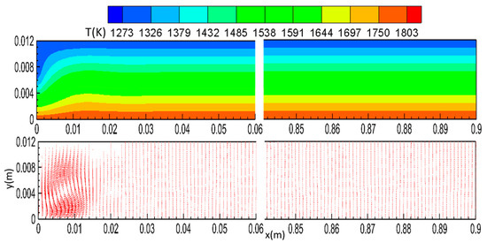
Figure 2.
Temperature and flow field of the liquid flux with the thickness of 12 mm.
When the thickness of liquid slag layer increases to 15 mm, the distribution of flow field and temperature field is shown in Figure 3. It can be seen that with the increase of slag layer thickness, the area of buoyancy flow of liquid slag along the casting direction expands, and natural convection vortex is generated in the slag layer. Rayleigh Bénard convection often occurs on a layer of fluid surface heated from the bottom. The fluid that undergoes convection forms on the surface and has a regular shape. The liquid at the bottom has a lower density due to the heating of the molten steel, and spontaneously forms regular vortices during its upward movement. The distance between the two vortex centers is about 14 mm, and the distribution of natural convection vortex inside the slag layer is relatively uniform, with the maximum flow speed of 0.213 mm/s. Due to the low temperature at the top of the liquid slag layer and the relatively high viscosity of the protective slag, a large flow resistance is generated, resulting in a smaller flow velocity of the protective slag at the top of the slag layer. As the thickness of the slag layer increases, the driving force of internal buoyancy flow will lead to the generation of natural convection vortices in the liquid slag layer, and the heat transfer effect of natural convection is also strong at this time.
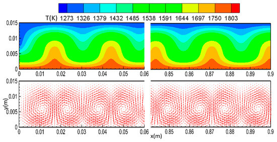
Figure 3.
Temperature and flow field of the liquid flux with the thickness of 15 mm.
3.2. Rayleigh Number
Rayleigh number (Ra) is a dimensionless parameter associated with heat transfer behavior in natural convection heat transfer. When Ra number is small than 101, the main mode of heat transfer is heat conduction; As the Ra number increases, heat transfer gradually becomes dominated by convective heat transfer. The calculation formula of Rayleigh number is as follows [14]:
When the viscosity of mold powder changes with temperature, Booker proposed to use the viscosity corresponding to the average temperature between two temperature boundaries to calculate the value of Rayleigh number. In this calculation, the average temperature between the bottom of the slag layer and the top of the slag layer is 1265.3 °C, at which time the viscosity of the protective slag is 1.02 Pa·s; When the thickness of slag layer increases from 12 mm to 15 mm, the corresponding Rayleigh number increases from 1977 to 3862, about 95.3%. By comparing the flow and temperature distribution of liquid slag under two different thicknesses, the increase in the thickness of slag layer will drive a significant Natural convection vortex in the slag layer, and the flow speed of liquid slag will be greatly accelerated, with the maximum flow rate increasing to more than four times. Therefore, without considering the shear velocity at the bottom of the steel/slag interface, when the thickness of the liquid slag layer increases from 12 mm to 15 mm, the heat transfer of the liquid slag will transition from heat conduction to mainly thermal convection.
3.3. The Effect of Bottom Shear Velocity on Liquid Slag Flow and Heat Transfer
During the casting process, the steel liquid flows out at a certain angle from the nozzle, and after the liquid steel reaches and collides with the narrow copper plate of the mold, it forms two streams of upper split flow and lower split flow. Among them, the upstream stream flows from the narrow copper plate towards the vicinity of the water inlet, forming an upstream reflux zone near the meniscus area. The flow state of molten steel in the upper reflux zone will promote a certain shear stress to act on the bottom of the slag layer, in the direction from the narrow surface of the mold to the water inlet, which corresponds to the shear velocity at the bottom of the slag layer during the calculation process.
When the bottom shear speed is 0.05 m/s, the flow field and temperature field under 12 mm, 15 mm and 18 mm slag layer thickness are calculated respectively. The results show that the temperature field and velocity distribution of mold fluxes with different thickness are the same. Taking the slag layer thickness of 12 mm as an example, the temperature field and flow field distribution of the protective slag are shown in Figure 4. Due to the effect of the bottom shear velocity, the natural convection vortex in the slag layer is greatly suppressed, and only a counter -recirculation zone is formed in the whole liquid slag layer area. The liquid slag near the water inlet flows upwards, thus the convective heat transfer of the liquid slag layer near the water inlet direction is significantly accelerated, forming a large temperature gradient. After the liquid slag flows to the top area of the slag layer, it turns to the horizontal direction and flows from the nozzle towards the narrow surface, opposite to the direction of the steel liquid flow. Based on the above analysis, it can be seen from the flow and temperature characteristics of the sintering layer/liquid slag layer interface that the heat transfer rate near the nozzle is higher along the casting direction, which can provide heat to the sintering layer in a shorter time and promote the melting of the protective slag. Therefore, in production, the amount of protective slag added in the nozzle area can be moderately increased to optimize the slag adding process and ensure that the thickness of the slag layer in the nozzle area is controlled within a reasonable range. In addition, the protective slag inside the slag layer is almost horizontally stratified flow, and the flow velocity direction is perpendicular to the heat flux density and temperature gradient direction. From the characteristics of flow and temperature distribution, after considering the bottom shear speed in the simulation calculation, although the heat transfer in the liquid slag layer may be dominated by heat conduction, the temperature distribution and flow state at this time have shown a significant difference from the calculation results when the shear speed is ignored, including the great difference in flow speed, circulation characteristics and temperature gradient, which has a significant impact on the heat absorption, melting and inflow of mold powder. This result also shows that it is necessary to consider natural convection, especially the bottom shear velocity.
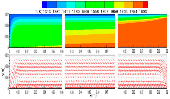
Figure 4.
Temperature and flow field of liquid flux layer with bottom shear velocity 0.05 m/s and the thickness of 12 mm.
When the thickness of the slag layer is 12 mm, at a distance of 450 mm from the center of the water inlet, the relationship between the horizontal flow velocity of the liquid slag in the thickness direction and the shear velocity is shown in Figure 5. It can be seen that with the increase of bottom shear velocity, the horizontal flow rate of liquid slag significantly accelerates. At a distance of 0.003~0.0035 m from the bottom of the slag layer, the flow direction of the liquid slag has changed. Taking this position as the boundary, the flow direction above it is from the mold nozzle to the narrow surface, with a wider area but a lower flow rate; the flow direction below it flows from a narrow surface to the nozzle, with a narrow area. However, due to being closer to the molten steel, the temperature is high, and the viscosity is low, resulting in a relatively high flow velocity in the horizontal direction. At a distance of about 0.00625 m from the bottom of the slag layer, the flow velocity towards the narrow surface of the mold reached its maximum value. When the bottom shear velocity increased from 0.005 m/s to 0.20 m/s, the maximum flow velocity increased from 0.0012 m/s to 0.0617 m/s. Within the range of 0.001 m from the top of the slag layer, the flow velocity of the liquid slag is almost zero. This is because the temperature at the top of the slag layer is low, the viscosity is high, and the flow ability of the liquid slag is relatively poor.
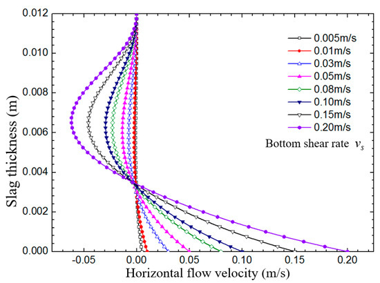
Figure 5.
Horizontal velocity in the thickness direction at a distance of 450 mm from submerged entry nozzle.
Under the action of bottom shear velocity, a counterclockwise reflux zone is formed within the slag layer. The longitudinal flow velocity distribution of liquid slag in the direction of slag layer thickness near the nozzle is shown in Figure 6. At a distance of about 2 mm from the bottom of the slag layer, the longitudinal flow velocity of the protective slag reaches its maximum value. The bottom shear velocity increased from 0.005 m/s to 0.2 m/s, the maximum longitudinal flow velocity increased from 0.0027 m/s to 0.12 m/s, and the average longitudinal flow velocity of liquid slag increased from 0.0012 m/s to 0.0627 m/s. It can be seen that as the surface flow velocity of liquid slag/steel increases, the convective heat transfer of the slag layer near the nozzle intensifies, and the heat absorption and melting of the protective slag are further enhanced.
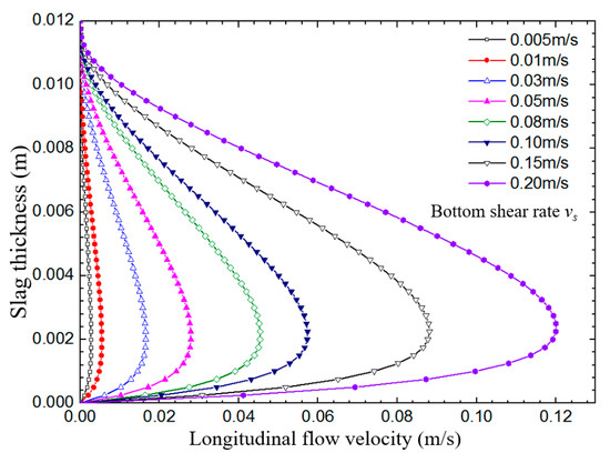
Figure 6.
Vertical velocity distribution in the thickness direction nearby submerged entry nozzle.
If the flow velocity in the reflux zone of molten steel is relatively small, the less active liquid surface is difficult to provide sufficient heat to the protective slag, thereby affecting the melting and subsequent inflow of the protective slag. If the velocity of the reflux zone on the molten steel is large, it is not conducive to the stability of the slag/steel interface, which can easily cause slag entrapment and affect the surface quality of the casting billet. Figure 7a shows the distribution of liquid slag temperature in the thickness direction in the central region of the model, and the relationship between the average heat flux of the liquid slag/steel interface and the liquid slag/sintering layer interface with the change of bottom shear velocity is shown in Figure 7b. When the shear speed is small (0.005~0.01 m/s), the longitudinal and horizontal flow velocities of the protective slag in the slag layer are relatively small. The heat transfer inside the slag layer is mainly through thermal conduction, and the temperature of the liquid slag layer is approximately linearly related to its distance from the interface. The average heat flux density between the liquid slag/steel liquid and the liquid slag/sintering layer interface is also small. When the bottom shear speed increases from 0.005 m/s to 0.2 m/s, the interfacial heat flux density of the liquid slag/steel liquid increases from 0.094 MW/m2 to 0.272 MW/m2, and the variation range of the interfacial heat flux density of the liquid slag/sintered layer is 0.096 MW/m2 to 0.273 MW/m2, which are very close. The difference in heat flux density is caused by weak heat transfer in the horizontal direction. Overall, with the increase of shear velocity, the heat conduction and convection inside the slag layer are significantly enhanced, and the temperature gradient inside the slag layer and interface heat flux density are significantly increased. The larger the bottom shear velocity, the wider the range of temperature fluctuations. The results are consistent with those of Neelakantnan, Mcdavid and Macias [8,9,10].
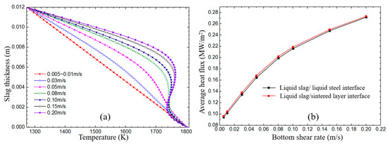
Figure 7.
(a) Temperature distribution in the thickness direction at a distance of 450 mm from submerged entry nozzle; (b) the average heat flux as a function of bottom shear velocity.
4. Discussion
Based on the Navier Stokes fluid momentum conservation equation and energy equation, a two-dimensional longitudinal numerical model was established to describe the flow/heat transfer behavior of liquid protective slag on the surface of molten steel. The results and calculated methods are applicable to different continuous casting machines. The main conclusions are as follows:
- (1)
- When the shear speed of the slag steel interface is not considered, with the increase of the thickness of the liquid slag layer, the driving of the internal buoyancy flow will lead to the natural convection vortex in the liquid slag layer, and the heat transfer effect of natural convection is also strong. When considering the effect of bottom shear velocity, the flow inside the liquid slag layer is basically laminar, and the heat transfer inside the liquid slag layer will mainly be heat conduction.
- (2)
- The shear stress formed at the bottom of the slag layer due to the flow of molten steel will promote the formation of a counterclockwise circulation zone within the slag layer. The heat transfer rate near the nozzle along the casting direction is relatively high, which can provide heat to the sintering layer in a shorter time and promote the melting of protective slag. Therefore, the amount of protective slag added in the nozzle area can be moderately increased in production to optimize the slag adding process and promote slag consumption.
- (3)
- The shear velocity formed at the steel/slag interface due to the flow of molten steel has a significant impact on the flow state of the protective slag. As the bottom shear velocity increases, the flow and heat transfer of the liquid slag layer will undergo significant changes, which cannot be ignored in numerical calculations and analysis. When the bottom shear velocity increases from 0.005 m/s to 0.2 m/s, the maximum flow velocity of liquid slag from the nozzle to the narrow surface in the center area of the model increases from 0.0012 m/s to 0.0617 m/s, and the average longitudinal flow velocity of liquid slag near the nozzle increases from 0.0012 m/s to 0.0627 m/s. The heat conduction and heat convection in the liquid slag layer significantly enhance with the increase of shear velocity.
Author Contributions
Data curation, S.W. and G.Z.; Writing—original draft, G.L. All authors have read and agreed to the published version of the manuscript.
Funding
This research received no external funding.
Institutional Review Board Statement
Not applicable.
Informed Consent Statement
Not applicable.
Data Availability Statement
Not applicable.
Conflicts of Interest
The authors declare no conflict of interest.
References
- Furumai, K.; Aramaki, N.; Oikawa, K. Influence of heat flux different between wide and narrow face in continuous casting mould on unevenness of hypo-peritectic steel solidification at off-corner. Ironmak. Steelmak. 2022, 49, 845–859. [Google Scholar] [CrossRef]
- Long, Q.; Wang, W.L.; Dou, K. Investigation on carbonizing from mold flux into ultra-low-carbon steel during continuous casting. Metal. Mater. Trans. B 2022, 54, 263–274. [Google Scholar] [CrossRef]
- Irie, S.; Tsuzumi, K.; Matsui, A.; Kikuchi, N. Estimation of changes in content and characteristics of mold flux during continuous casting. ISIJ Int. 2023, 63, 516–524. [Google Scholar] [CrossRef]
- Yang, J.; Wang, L.J.; Li, Y.; Wang, T.J.; Kong, L.Z.; Zhang, X.M. Modeling of Flux Reaction and Mixing in Continuous Casting Mold of Medium Mn Steel. Metal. Mater. Trans. B 2022, 53, 1516–1525. [Google Scholar] [CrossRef]
- Dozhdikov, V.I.; Cherkasov, N.V.; Vasyutin, A.Y.; Ganul, A.O. Simulation of the Heat-Transfer Conditions in a CCM Mold. Metallurgist 2022, 66, 610–616. [Google Scholar] [CrossRef]
- Meng, Y.; Thomas, B.G. Heat-transfer and solidification model of continuous slab casting: CON1D. Metal. Mater. Trans. B. 2003, 34, 685–705. [Google Scholar] [CrossRef]
- Han, F.N.; Wen, G.H.; Zhang, F.; Wang, Z.; Yu, L. Effect of Microstructure on the Granule Strength of Hollow Granulated Mold Fluxes for Continuous Casting. Steel Res. Int. 2023, 94, 2200480. [Google Scholar] [CrossRef]
- Neelakantan, V.N.; Sridhar, S.; Mills, K.C.; Sichen, D. Mathematical model to simulate the temperature and composition distribution inside the flux layer of a continuous casting mould. Scand. J. Metall. 2002, 31, 191–200. [Google Scholar] [CrossRef]
- Mcdavid, R.M.; Thomas, B.G. Flow and thermal behavior of the top surface flux/powder layers in continuous casting molds. Metall. Mater. Trans. B. 1996, 27, 672–685. [Google Scholar] [CrossRef]
- Macias, A.E.; Castillejos, E.A.H.; Acosta, G.F.A.; Herrera, M.; Neumann, F. Modelling molten flux layer thickness profiles in compact strip process moulds for continuous thin slab casting. Ironmak. Steelmak. 2002, 29, 347–358. [Google Scholar] [CrossRef]
- Xu, L.; Pei, Q.W.; Han, Z.F.; Wang, E.A.; Wang, J.Y.; Karcher, C. Modeling study of EMBr effects on molten steel flow, heat transfer and solidification in a continuous casting mold. Metall. Res. Technol. 2023, 120, 218. [Google Scholar] [CrossRef]
- Swain, A.N.S.S.; Ganguly, S.; Sengupta, A.; Chacko, E.Z.; Dhakate, S.; Pandey, P.K. Investigation of corner cracks in continuous casting billet using thermomechanical model and plant measurements. Met. Mater. Int. 2022, 28, 2434–2447. [Google Scholar] [CrossRef]
- Thaps, S.; Wang, M.Q.; Silaen, A.K.; Ferreira, M.E.; RollingS, W.; Zhou, C. Application of electromagnetic braking to minimize a surface wave in a continuous caster. Materials 2023, 16, 1042. [Google Scholar] [CrossRef] [PubMed]
- Zhao, B.; Vanka, S.P.; Thomas, B.G. Numerical study of flow and heat transfer in a molten flux layer. Int. J. Heat Fluid Flow 2005, 26, 105–118. [Google Scholar] [CrossRef]
Disclaimer/Publisher’s Note: The statements, opinions and data contained in all publications are solely those of the individual author(s) and contributor(s) and not of MDPI and/or the editor(s). MDPI and/or the editor(s) disclaim responsibility for any injury to people or property resulting from any ideas, methods, instructions or products referred to in the content. |
© 2023 by the authors. Licensee MDPI, Basel, Switzerland. This article is an open access article distributed under the terms and conditions of the Creative Commons Attribution (CC BY) license (https://creativecommons.org/licenses/by/4.0/).