Review

Micro-Arcs Oxidation Layer Formation on Aluminium and Coatings Tribological Properties—A Review

1
Galvanoplastie Industrielle Toulousaine, 31270 Cugnaux, France
2
Laboratoire Génie de Production, 65000 Tarbes, France
*
Author to whom correspondence should be addressed.
Coatings 2023, 13(2), 373; https://doi.org/10.3390/coatings13020373
Submission received: 24 October 2022 / Revised: 25 January 2023 / Accepted: 30 January 2023 / Published: 6 February 2023

Abstract

:
This review proposes to carry out a state-of-the-art associated with micro-arc oxidation. Firstly, the different aspects of the growth mechanisms of the oxides are detailed. Then, the formation of micro-arcs and the case of soft-spark treatment are discussed. Then, the electrolytic reactions involved in the layer construction are outlined. We focused on the influence of aluminium alloys on the appearance of the coating and its characteristics before considering the electrolyte formulation. We have concentrated some of our efforts on silicate-based electrolytes, mainly used in research and industry. The importance of electrical parameters in layer formation is detailed later. The main factors studied in the literature are the current source, current density, treatment frequency and duration, and duty cycle. We have also noted the different phase compositions identified in the literature. Finally, since the process is particularly advantageous for protecting the surfaces of aluminium parts against wear, we conclude this review by presenting work on the tribological properties of this coating. In this final section, we highlight the work on the wear-reducing properties and tribological mechanisms identified in the literature. Particular attention is paid to the relationship between the nature of the substrates used, the role of the electrolyte and the counterpart choice on the friction and wear results.

1. Introduction

Innovative solutions could reduce energy losses due to friction and wear by about 40% over 15 years [1]. Due to its low density and abundance, aluminium, the world’s most widely used non-ferrous metal, remains essential for reducing the overall mass of systems and the energy consumed to operate them. However, its low hardness makes it susceptible to abrasive wear. Therefore, various processes have been developed to increase the surface hardness of aluminium parts.
Processes can be applied to valve metals such as aluminium and its alloys to overcome these weaknesses. These include anodising, chemical conversion coating, chemical or physical vapour, deposition electrolysis, laser surface treatment, organic coating, and thermal or cold spraying [2].
mao can be used to produce coatings on valve metals [3] and non-valve [4] or mixed alloys such as AlSi [5] or Al6Cu [6]. The advantage of MAO is that, although the power consumption can be high, overall, the POE process, particularly the bath chemistry, is simple, safe and environmentally friendly. It is possible to treat all alloys without distinction. The coating results in a high hardness compared to all other processes. The assembly allows the preparation of very large parts with complex geometry. These coatings meet the need for wear and corrosion resistance, refractory properties, electrical insulation and sometimes for decoration [7].
The applications are numerous, particularly in the transport sector: for the automotive and aeronautical industries and in the biomedical, electronic, and aerospace fields, where it is preferred to other conventional surface treatment processes on titanium, magnesium and aluminium alloys [5,8,9,10,11]. These include the rotors and centring ring of turbomolecular pumps, facilities for astrobiological experiments during the ISS exposure programme, a heat sink, die-cast optical components and plates for osteosynthesis, scanned body locators and stents for the treatment of coronary problems. Using mao on various materials [12]. Other work attempts to use surface structuring processes at the micro or even manometric scale to produce hydrophobic surfaces [13]. More original still, additives are sometimes used in the electrolyte to induce phosphorescence [14].
It is possible to add microparticles or nanoparticles to the electrolyte to enhance or bring out new properties, but this work will not be the subject of this review. Instead, we will focus our attention on MOA coatings on aluminium alloys.
Hard anodic oxidation (ha) is the most common treatment to improve the wear resistance of aluminium parts. It achieves a hardness in the range of 450 to 600 HV.
On the other hand, micro-arc oxidation (mao) is a good surface treatment process designed to limit wear on parts. This treatment also complies with REACH regulations. This acronym stands for «registration, evaluation and authorisation of chemicals»: a European regulation (Regulation 1907/2006) that came into effect in 2007 to secure the manufacture and use of chemicals in the European industry [15,16].
It has been shown that the corrosion resistance of aluminium alloy can be greatly increased by using different surface treatments. For example, mao coating gives a higher level of corrosion resistance than Plasma Spray Ceramic (PSC), and Hard Anodizing (HA) coatings [9,17,18].
In 1882, Sluginov reported the presence of a light phenomenon during an electrolysis experiment [19]. However, Gunterschultze and Betz were the first to publish on the formation of an anodic spark deposition (asd) in the 1930s [20,21]. The authors pointed out the appearance of luminous sparks on the surface of the specimens throughout the treatment. The first industrial applications of this process were patented in the 1960s to combat corrosion on magnesium alloys. In 1976, the first coatings by micro-arc oxidation on aluminium were produced in urss [22,23,24]. After the break-up of the Soviet Union, the rest of the world discovers these works.
Indiscriminately, the literature refers to micro-arc oxidation (mao) [25], electrolytic plasma oxidation (peo) [26] or anodic spark deposition (asd) [27]. This surface treatment process permits an oxide layer to grow on valve metals. These metals allow the current to flow in only one direction of the metal/oxide/electrolyte system [28]. The thick layers, up to 500 µm [29], have a high adhesion with the substrate and are recognised for their mechanical properties.
Several types of electrolytes exist. The most commonly used is alkaline, based on low-concentration silicates and has no dissolving action on the layer. It also has the advantage of treating all types of aluminium alloys, unlike copper-rich alloys, which are difficult to treat with electrolytes.
The complexity and the diversity of investigation on this coating lie in the fact that no operating parameters are fixed. Thus, each research group produces and focuses on a different coating.
Therefore, this section is first to gather the different operating conditions identified in the bibliography allowing the formation of coatings by micro-arc oxidation. The substrate nature, the electrolyte composition, and the electrical parameters of treatment are also noted. Many conditions on an aluminium electrode surface allow the electric arc to initiate an oxide coating. However, the selection of the different parameters strongly influences the nature and morphology of the layers formed. The literature supports, specifically, the importance of the composition of the substrate, the surface roughness, the formulation of the electrolyte, and the electrical conditions of treatment on the quality and properties of the coatings made bymao [27].

2. Micro-Arcs Oxidation Layer Formation

This section presents a state-of-the-art of the different advances that allow us to understand the formation of the mao layer. The different growth mechanisms identified show the need to understand how micro-arcs are created. The electrochemical reactions explaining the formation of the oxide are also identified. Finally, the importance of the nature of the substrate is studied.

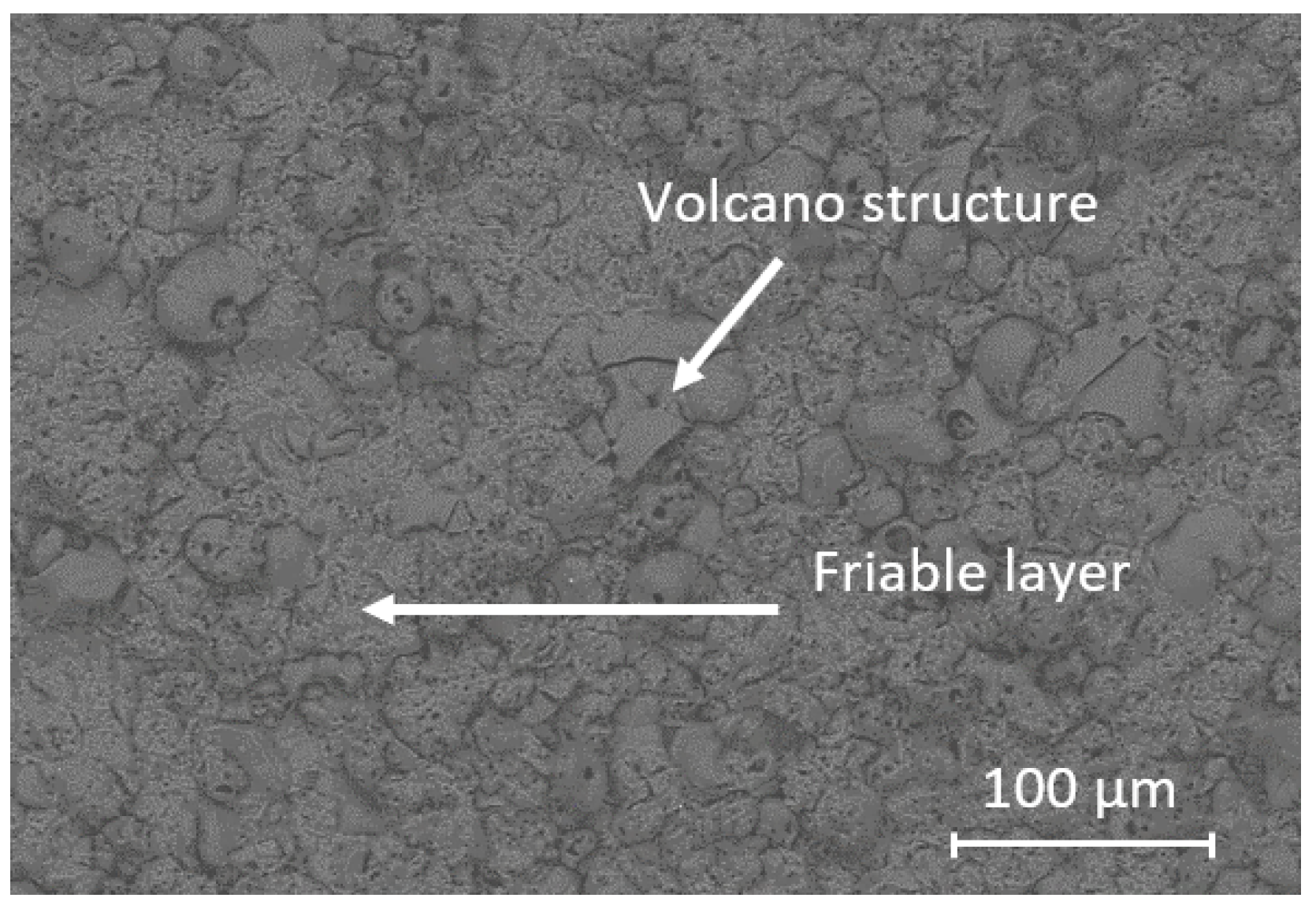
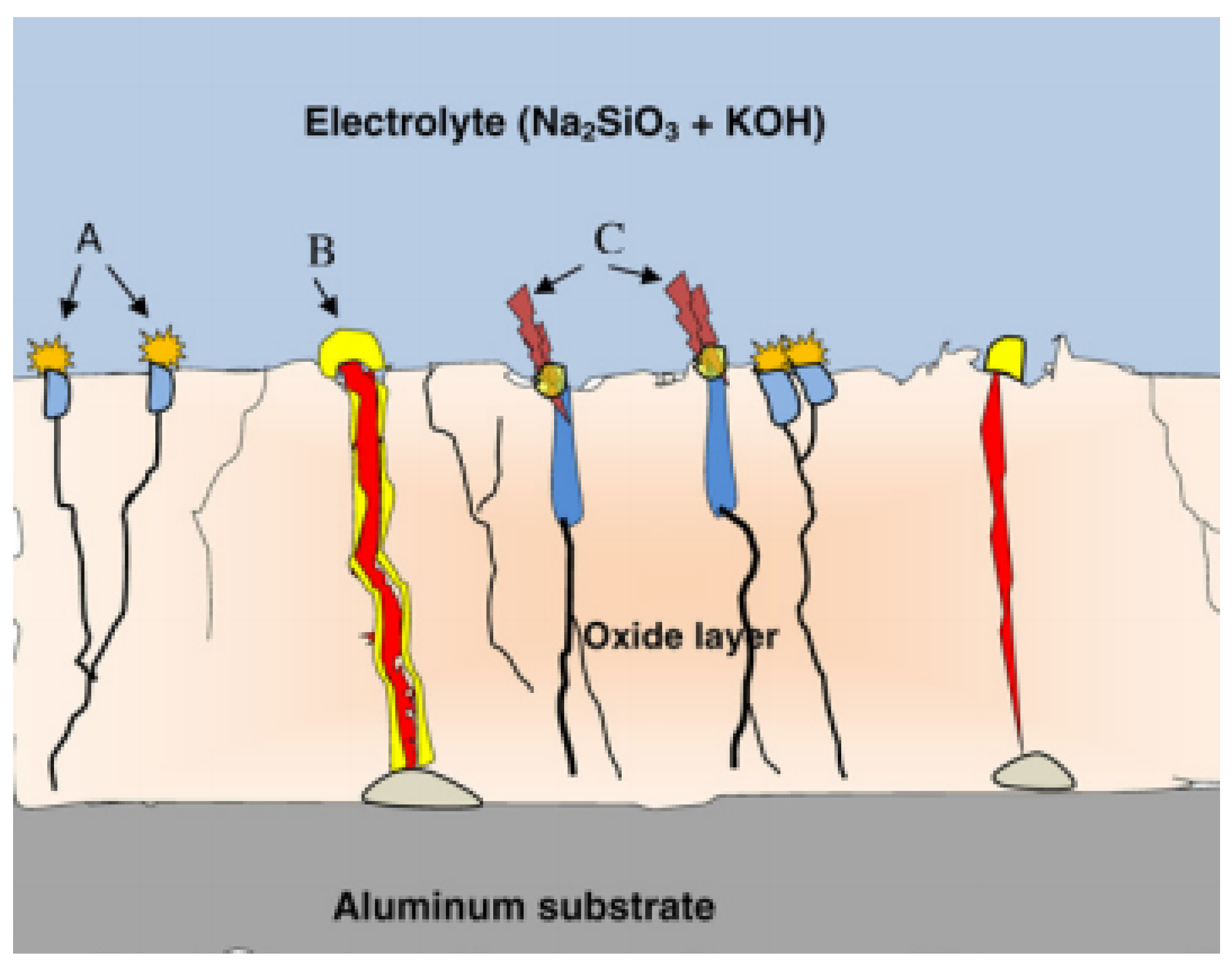
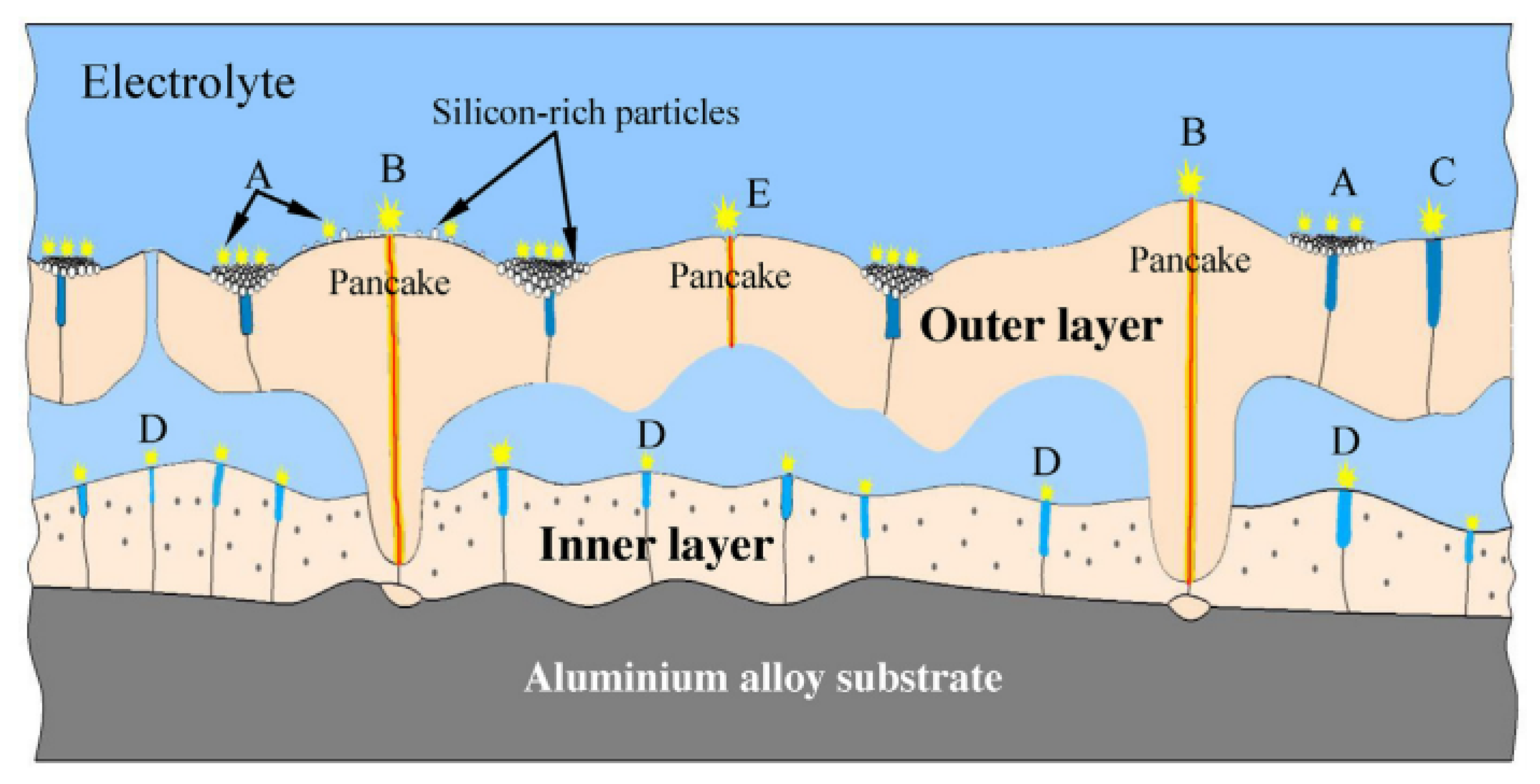
2.1. Oxide Growth Mechanism

The oxide formation during a surface treatment by micro-arcs oxidation can be broken down into three stages. In the first stage, many micro-arcs are formed in the oxide layer. This phenomenon results from the loss of dielectric stability in a region of low conductivity (dielectric breakdown). This dielectric breakdown leads to the passage of an avalanche of electrons causing a local temperature rise. The temperature reaches about 7000 K [30,31,32,33] in the central part and is surrounded by a zone of lower temperature (about 3500 K [34]) The intense electric field (10 6 –10 7 V/m [31]) causes the ejection of anionic compounds into the discharge channel. On the other hand, the metal compounds in plasma are ejected from the substrate through the discharge channel, where they are oxidised. The plasma chemical reactions in the channels result in a pressure increase of around 10 2 MPa [35].
Furthermore, oxygen concentrations are dissolved in the alumina at the system’s high temperatures and pressures. These species form small-scale connected porosity during cooling of the oxide [36]. Simultaneously, the electrostatic forces of the imposed electric field cause the cations to evacuate to the electrolyte.
In the second stage, the oxidised metal is ejected through the discharge channel. This metal then cools on the surface of the coating in contact with the electrolyte. The phenomenon causes the layer to grow around the channel, forming a characteristic volcano structure on the surface [Figure 1]. Finally, the cooling also deposits the reaction products on the channel walls.
The discrete repetition of this phenomenon across the substrate surface results in the constant growth of the coating. Three discharge initiation sites were identified [36,37] [Figure 2]:
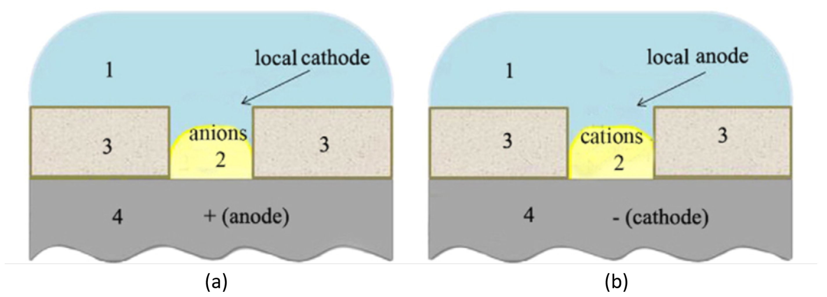
  • Site B: oxide breakdown occurs down to the metal substrate when the electric field reaches a critical value. A discharge channel is created in which the plasma reactions take place. The high temperature and intense electric field cause the molten aluminium to escape from the substrate/coating interface to the coating surface, where the electrolyte rapidly cools it.
  • Site A and C: These sites refer to the breakdown of the oxide to the gas pockets present in the internal pores (micropores) of the oxide. In the case of A sites, the micropores are present towards the surface of the oxide. In the case of C sites, the micropores are deeper in the layer.
Further studies propose an additional breakdown site (D sites). These micro-arcs occur in large-diameter pores at the interface between the inner (dense) and outer (friable) layers. Indeed, these gas-filled pores have a breakdown voltage about an order of magnitude lower than that of alumina [38]. These discharges of type D cause the growth of the internal layer with the incorporation of the elements of the electrolyte. In addition, some of the volcanoes visible on the surface of the outer layer are no longer visible after their removal. Therefore, they do not extend into the inner layer or the substrate.
Finally, the fifth type of discharge (Type E) can be identified. These discharges could form limited volcano structures in the outer layer of the coating [Figure 3].
This model of layer formation mao can be paralleled with the model of landfill evolution.
Indeed, the evolution of the voltage as a function of time makes it possible to observe the distinct stages of the current-voltage evolution noted during the formation of the arcs in the oxide layer [27,35,36,37,40] [Figure 4]:
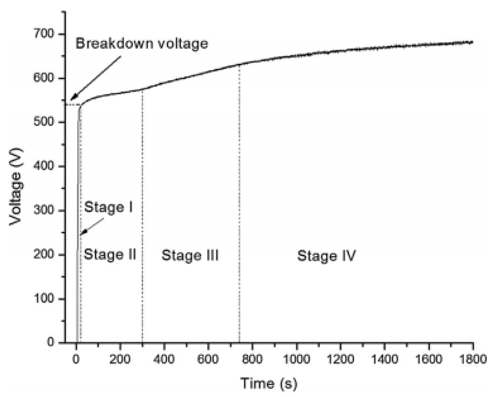
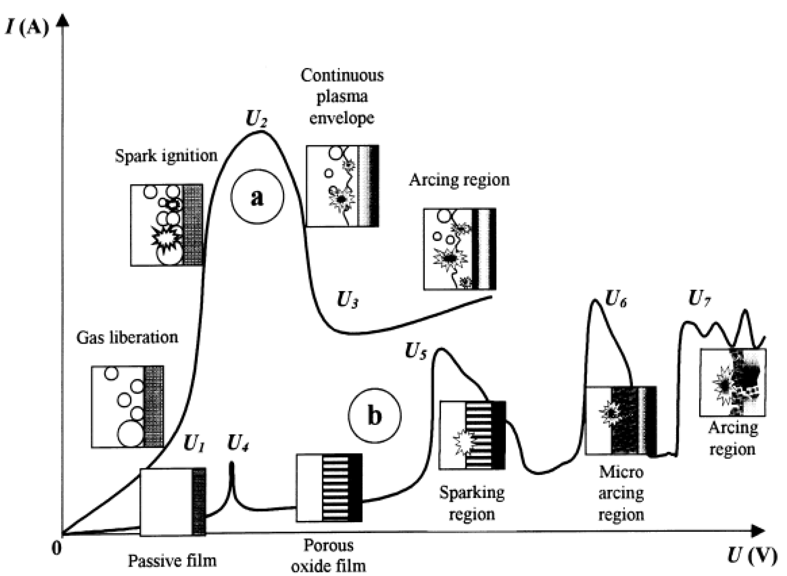
  • step 1: rapid electrochemical formation of the insulating oxide layer causing a rapid linear increase in the measured output voltage. The breakdown voltage is not reached. This first step is similar to conventional anodising and follows Faraday’s law;
  • Step 2: the rate of voltage change increases less rapidly. The oxide breakdown voltage is reached. Numerous micro-arcs (sparks) appear at high frequency over the entire surface of the sample. This phenomenon shows the beginning of the decomposition of the oxide layer;
  • the increase in the rate of change of voltage has slowed down compared to that of step 2. The micro-arcs appear at a lower frequency and are more intense. As the oxide grows, the layer’s electrical resistance increases. As the discharges are more intense, the temperature is higher, allowing all the species present to be excited instead of just the decomposition of the oxide. This causes a change in the plasma;
  • step 4: The rate of voltage change is even slower than during step 3. More intense discharges are observed, and the micro-arcs last longer. The frequency of occurrence of these discharges is less than in step 3 because of the even greater thickness of the coating. In some cases, these discharges cause irreversible degradation of the coating.
Most of the discharges occurring in the B-sites occur in the step 2 when the oxide is still thin. Fluctuations in signal strength observed at the stages 3 and 4 also reflect the different breakdown sites. The strong signals come from the total breakdown of the oxide in the B sites. The medium-intensity micro-arcs occur at the C sites, while the lower-intensity micro-arcs come from the A sites. The very high intensity of the discharges during step 4 shows that the majority of the micro-arcs are in the B-sites [37].
The different sites of appearance of the discharges presented previously confirm that the formation of the layer of mao takes place in several stages. These different types of micro-arcs are associated with characteristic phases and oxide morphologies. A correlation between the nature of the micro-arcs, the thickness of the surface layer and the phase composition is observed. The increase in the micro discharges’ intensity caused by the layer’s increasing thickness leads to the conversion of alumina phases into textured alumina. Indeed, the low thermal conductivity of alumina allows it to store and accumulate the energy supplied by the discharges occurring in the vicinity. This energy is then partly dissipated, allowing alumina to crystallise and transition to more thermodynamically stable phases. The increase in the concentration of -Al 2 O 3 in the thicker layers coincides with the appearance of high-intensity micro-arcs and a more prolonged energy accumulation time. These conditions will likely provide the coating with sufficient local energy for enough time to induce the γ → α [41] phase transition.

2.2. Micro-Arcs Formation

The energisation of the electrode in the electrolyte initiates the start of the anodising process. As the voltage increases, different process stages follow each other, causing arc generation. It has been observed that when an oxide layer reaches a specific thickness, dielectric breakdown occurs and terminates the Faraday growth of the oxide. Dielectric breakdown phenomena have been the research subject for many years, but a clear understanding of their mechanisms has yet to be achieved.
A visible spark and an audible snap accompany the dielectric breakdown. The value of the breakdown voltage ( U B ) depends mainly on the nature of the anodised metal, the thickness of the oxide, the composition of the electrolyte, the pH, and the resistivity of the electrolyte. It is, however, independent of current density, temperature, surface topography and electrolyte stirring rate.
The first set of models proposes a mechanism for forming electric arcs in the oxide layer [41,42,43,44,45]. Intense electric fields cause a local rise in the temperature of the oxide by the Joule effect. The application of the field increases the movement of the ions and thus accelerates the accumulation of heat. When its value exceeds the breakdown voltage, the oxide structure is sufficiently disordered so ions can pass directly through the disordered oxide structure rather than through gaps. This change causes atoms and ions to collide as they move through the oxide layer, resulting in micro-arcs. Therefore, the low density of charge carriers causes the formation of micro-arcs. Indeed, when the thickness of the oxide layer increases, the equivalent resistance of the system increases; therefore, the necessary breakdown voltage also increases.
The second category of models considers that a gaseous phase or a mixed vapour/gas phase between the electrolyte and the metal substrate would be necessary for plasma to form on the surface of the working electrode [41,46,47]. The formation of a gas phase in the pore, as well as the ignition of this phase, is assumed to be induced by an initial dielectric breakdown of a barrier layer at the bottom of the micropore. Rakoch’s work hypothesises that the establishment of microplasma discharges at the cathode is possible due to the recharging of the interface between the vapour/gas phases and the electrolyte that occurs during the transition between the polarisations of the working electrode [Figure 5] [47]. The vapour phase is found in the discharge channels of the coating and is formed during the anodic polarisation of the working electrode. It is then necessary for the electrolyte to acidify locally to allow cathodic and anodic micro-arcs to form.
The characteristic curve describing the evolution of the current as a function of the applied voltage depends on the place of formation of the discharges [Figure 6] [29]:
  • the curve of type-a represents the current-voltage behaviour with the formation of discharge in the gas phase near the surface of the electrodes [Figure 6];
  • the curve (type-b) presents the relationship between current and voltage for discharges occurring in the oxide layer.
At relatively low voltages, the kinetics of the reactions at the electrodes of both systems follow Faraday’s law, and the characteristics of the cell created change according to Ohm’s law. This change increases the thickness of the oxide formed and the release of hydrogen gas. This phenomenon is visible in the 0-U1 zones of the type-a system and 0-U4 of the type-b system. However, from a specific voltage, the behaviour of each of the systems changes completely.
In the U1-U2 zone of the type-a system, the increase in voltage causes the current to oscillate, and the first light emissions are observed. A partial shielding effect formed by the gaseous reaction products (O 2 and H 2 ) limits the current increase. However, the current density continues to increase at the surface of the electrode remaining in contact with the electrolyte, leading to localised boiling.
At point U2, the electrode is completely covered by a plasma of low electrical conductivity. In this region close to the electrode, the values of the imposed electric field are sufficient to start the ionisation process of the vapours. High-frequency sparks manifest this ionisation phenomenon in the gas bubbles around the sample. The hydrodynamic stabilisation of the gas envelope causes the current to fall in the U2-U3 region. Once the U3 point is passed, the glow discharges become more intense arcs characterised by a lower acoustic emission frequency.
At point U4 of the system, the passive film formed earlier begins to dissolve. In practice, this phenomenon occurs at the corrosion potential of the material. The repassivation region corresponds to U4-U5. A porous oxide forms and is responsible for most voltage drops in this area.
At the U5 point, the electric field in the oxide reaches a critical value at which dielectric breakdown of the layer occurs either by tunnel ionisation or by impact ionisation. At this point, sparks of low luminosity appear successively over the entire surface of the oxide.
At U6, the impact ionisation mechanism is assisted by the onset of thermal ionisation. The micro-arcs are less frequent and more intense.
In the U6-U7 region, thermal ionisation is partially limited by the increasing number of negative charges in the growing thickness of the oxide. This phenomenon reduces the duration and intensity of the discharges. At this stage, we speak of micro-discharges or micro-arcs. Under the effect of these micro-arcs, the oxide is melted and then alloyed with the elements of the electrolytic bath. At the U7 stage, the micro-arcs are strong enough to penetrate the entire oxide and reach the substrate [29].
The presentation of these models shows that no consensus has been found to explain how these electrical micro-arcs are formed. Other models resulting from the study of phenomena that can approach a mao are sometimes put forward to give new hypotheses of mechanisms [41].

2.2.1. Special Case of the Soft-Arc Regime

The soft sparking mode is observed under certain AC processing conditions. This phenomenon helps the formation of alpha alumina in the coating while maintaining the entire substrate at room temperature. The hardest coatings are [48,49] with the highest proportion of dense layer [50,51,52,53,54] and with the most uniform thickness [52,54] are obtained in this manner. This method of treatment also makes it possible to reduce the roughness [55] as well as the porosity [52,56].
The cathodic current reduces the size of the charge zone formed during the anodic polarisation of the metal/oxide/electrolyte system. This increases the coating’s electronic conductivity, helping to assist hydrogen evolution and basify the adjacent electrolyte. The subsequent anodic discharges then occur in the hydrogen-rich regions and promote dehydration and phase change of the hydrated alumina [57].

2.2.2. Electrochemical Reactions

Oxide growth during the mao treatment occurs when the aluminium working electrode is in anode condition. The oxidation of the surface can be described by electrochemical reactions occurring at the interface between the aluminium and the oxide [58]:
A l ( m ) = A l A l ( o x ) + 3 2 V O 2 + ( o x ) + 3 e
A l ( m ) + V A l 3 ( o x ) = A l A l ( o x ) + 3 e
where
  • Al(m) corresponds to the normal position of an aluminium atom in the metal;
  • AlAl(ox) corresponds to the normal position of an aluminium atom in the oxide;
  • V O 2 + is an oxygen vacancy in the oxide ;
  • V Al 3 is an aluminium vacancy in the oxide ;
  • e is an electron.
At the oxide/electrolyte interface, the possible chemical reactions are:
A l A l ( o x ) = A l 3 + ( a q ) + V A l 3 ( o x )
H 2 O + V O 2 + ( o x ) = O O ( o x ) + 2 H + ( a q )
H O = O O ( o x ) + 2 3 V A l 3 ( o x ) + H + ( a q )
H O + V O 2 + ( o x ) = O O ( o x ) + H + ( a q )
where
  • Al3+ (aq) is the aluminium ion dissolved in the aqueous electrolyte;
  • OO(ox) is an oxygen atom present in the oxide;
  • H+ (aq) is a hydrogen ion in the aqueous electrolyte.
Combining the reactions (1) and (6) gives the reaction for the formation of aluminium oxide in an aqueous medium:
2 A l + 3 O H = A l 2 O 3 + 3 H + + 6 e
As Al 3 + ions are not stable in alkaline solutions, the formation of V Al 3 (ox) charge carriers occurs according to the reaction (5). The reaction (2) could occur at the interface between the oxide and the electrolyte. In this case, the pH would decrease near the surface of the oxide.

2.3. Nature of the Substrates

There is relatively little information in the literature on the effect of the substrate on the treatment of mao. However, Godja’s work has shown that the presence of the alloying elements constituting the aluminium strongly impacts the quality of the coating formed. Indeed, these elements react with the electrolyte during the treatment and form soluble products. This phenomenon then increases the porosity and roughness of the coating [27].
The various mechanisms involved in forming the layer are generally well understood. However, some physical phenomena, such as the exact nature of the discharges and the precise breakdown mechanism, still need to be agreed upon and clarified.

3. Importance of the Electrolyte

The previous section described the understanding of the mechanisms involved in the formation of the layer. It is now necessary to understand the physicochemical environment. The primary role of pH is discussed and the various electrolytes identified are mentioned. The case of silicate-based electrolytes, mainly used at present, is discussed.

3.1. Role of pH in MAO Treatment

A decrease in breakdown voltage is observed with an increase in the electrolyte’s hydrogen potential (pH) [59]. The authors suggest that the amount of charge carriers required to cause layer breakdown is less when the HO concentration is high. It was also noted that a decrease in the pH of the electrolyte favours the integration of silicon with the porous outer layer of the coating [60].
The isoelectric point (iep) is defined as the pH of an aqueous solution in which a solid exists at the neutral electrical potential. Aluminium is at pH = 9.1. The modification of the pH allows the energy released by the anodic and cathodic micro-arcs during a deposition process to be controlled. Indeed, only the presence of H + cations in the electrolyte allows the initiation of micro-arcs in the cathodic phase.
The electrode immersed in an electrolyte can be considered an electrical double-layer model (edl) whose structure strongly depends on the composition of the electrolyte. This type of model is used to represent the surface of any solid exposed to a fluid. The first layer (or compact layer) represents the surface charge of the object. It consists of the ions adsorbed by chemical interactions. The second layer, also called the diffuse layer, is composed of ions attracted by the charge of the first layer. It is made up of free ions which move in the fluid under the influence of electrical attractions and thermal movements.
In the case of an electrolyte at pH > iep, the oxide surface tends to be deprotonated. A first negatively charged layer is thus formed on the oxide surface, which must be compensated by a diffuse layer of cations [Figure 7]. During anodic polarisation, the internal field of the electric double layer is opposed to the external field imposed by the generator. At a specific voltage, a breakdown can occur [Figure 7a]. Under cathodic polarisation, the electric field in the compact layer and the field caused by the external source coincide, making it impossible for arcing to occur [Figure 7b].
The atomic radius of the protons allows them to have a longer mean free path and kinetic energy than other cations at a given electric field [47]. A low electric field can therefore accelerate them sufficiently to bombard the vapour phase molecules and the metal substrate at the bottom of the discharge channels. The electrons torn off the bombarded elements can trigger an electronic avalanche and a micro-arc [47]. For pH values above 11, the protons cannot be sufficiently concentrated at the interface. The breakdown of the gas and vapour phases would be due to the presence of other cations at the interface [47].
In the case where the pH is lower than the iep, the protonation of the compact layer is compensated by a higher concentration of anions in the diffuse layer. In cathodic polarization, the internal field thus opposes the external field. Conversely, the two electric fields are oriented in the same direction in anodic polarisation. A potential barrier appears in cathodic polarisation and disappears in anodic polarisation. When the internal and external fields are oriented in the same direction in anodic polarisation, the potential barrier decreases and causes a depolarisation of the electrode [57]. However, it is also known that the mao carried out on aluminium alloys at pH < iep do not make it possible to obtain coatings that are thick enough to allow the appearance of a regime of micro-arcs [51,52,61,62].

3.2. Different Electrolytes Used

The electrolytes used during the mao processes on aluminium alloys can be classified into six different groups [29]:
  • electrolytes causing rapid dissolution of aluminium such as NaCl, NaClO 3 , NaOH, HCl, NaNO 3 ;
  • electrolytes causing slow dissolution of aluminium such as H 2 SO 4 , (NH 4 ), S 2 O 8 , Na 2 SO 4 ;
  • electrolytes that promote metal passivation in a narrow voltage range, such as sodium acetate and phosphoric acid;
  • fluoride-based electrolytes (KF and NaF);
  • electrolytes causing slight passivation of the metal substrate;
  • electrolytes causing strong passivation of the metal such as boric acids; and salts of carbonic and phosphoric acid, inorganic polymers (such as silicates, aluminates, tungstates, molybdates) and alkali metal phosphates.
The decrease reduces the dissolution of the oxide layer in the concentration of hydroxide ions on the surface. Micro-arcs can therefore be formed in electrolytes with relatively high pH. The concentration of HO is a lever used to allow the formation of the layer. Khan et al. demonstrate that the growth rate decreases with the KOH concentration of the electrolyte [63].
The presence of hydroxyls decreases the value of the breakdown voltage of the system by lowering the resistivity of the electrolyte [58,60]. However, an increase in its concentration leads to a decrease in the growth rate of the layer. Indeed, increasing the concentration of this species in the solution also increases the number of HO ions adsorbed on the oxide surface. The adsorption of this species on the surface of the oxide causes the dissolution of the coating through the reactions (Equation (8)), (Equation (9)) or (Equation (10)). The rate of insertion of HO into the layer is dependent on both the concentration of O 2 vacancies on the oxide surface (V O 2 + (ox)) and the applied electric field. Too much HO adsorbed leads to the dissolution of the coating [58].
Al 2 O 3 + HO = 2 AlO 2 + H +
AlOOH + HO = AlO 2 + H 2 O
Al ( OH ) 3 + HO = Al ( OH ) 4
Furthermore, hydroxide ions are bound to cations when added to the electrolyte. The importance of these cations has been studied [57]. It is shown that the different electrical and optical characteristics of the process of mao are influenced by their nature. Indeed, the cathodic charge transfer capacity in the metal/oxide/electrolyte system is maximal in the presence of Na + and K + . These cations also play an essential role in the formation of crystalline phases. This work shows that no crystalline phase is formed without cations with a single positive charge.
Godja’s work has shown that electrolytes containing NaOH and used with an alternating voltage cause thicker layers with high porosity formation. Furthermore, adding polyphosphate to DC electrolytes results in thinner, denser coatings with better corrosion resistance [27].

3.3. Case of Silicate-Based Electrolytes

The following work focuses on sodium silicate (Na 2 SiO 3 ) electrolytes combined with other elements that increase the conductivity of the electrolyte. The addition of sodium silicate (Na 2 SiO 3 ) maximises the growth rate, and the coating thickness [38,60]. The presence of this species in the electrolyte at concentrations between 1 and 10 g/L makes it possible to increase the breakdown voltage value of the oxide slightly. Indeed, the adsorption of SiO 3 2 by the oxide increases its thickness [54,60]. Moreover, the adsorption of silicate competes with that of HO and allows the dissolution of the layer to be reduced. The growth rate of the coating is then increased [60,64]. Sodium silicate is generally associated with NaF (0.5 to 20 g/L), NaOH or KOH (1 to 50 g/L).
There is a lack in the state of the art of the physicochemical role of electrolyte conductivity and the optimisation of this parameter. Furthermore, a detailed description of the impact of ionic species and their choice still needs to be sufficiently developed to optimise the electrolyte selection according to the desired coating properties.

4. Electrical Parameters

Many authors have studied the influence of different electrical parameters to understand and adapt the layer’s parameters to be used as best as possible according to the intended application.

4.1. Effect of the Current Source

Historically, mao is formed at high DC anode voltages [65]. The coatings formed in this way were porous and non-uniform. The use of an alternating current was then implemented to interrupt the formation of discharges and thus limit the appearance of the most intense micro-arcs, also called macro-arcs. An alternating current source also influences other factors. The overload effect causes the formation of a current through the metal/oxide/electrolyte system, similar to that encountered in capacitor-type electrical circuits. Secondly, the hydrogen release mechanism during the negative phase provides a gaseous medium supporting the plasma in the vicinity of the oxide/electrolyte interface from the beginning of the oxidation. Finally, some authors suggest that discharges can occur in the oxide during the negative current phase. This phenomenon would occur mainly in the last stages of the formation of the layer (see the model of the evolution of the discharges) [54].
The cathodic polarisation that occurs with AC sources can cause both an increase and a decrease in local pH depending on the reactions that occur on the surface:
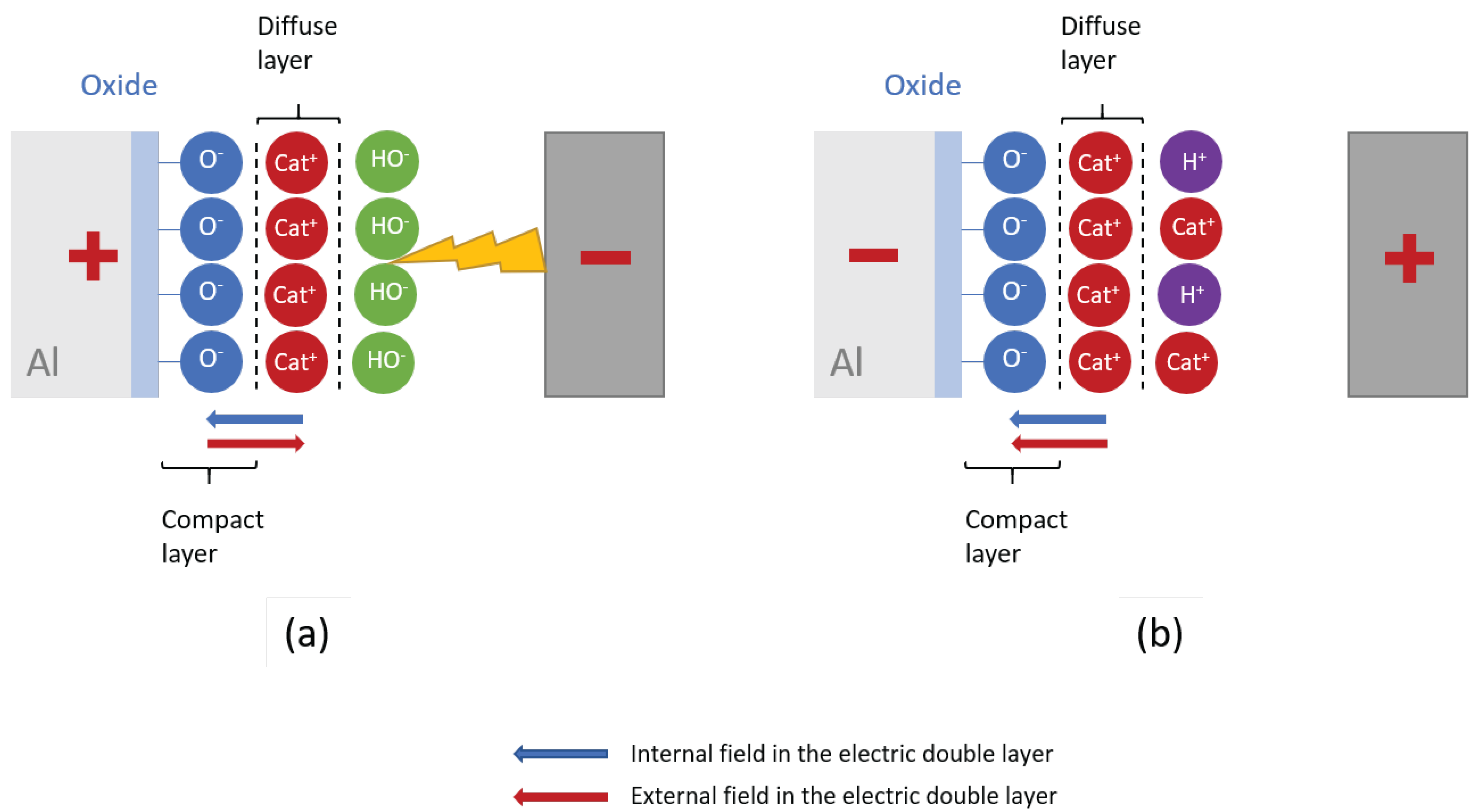
  • the first case studied is that for which the surface layer can support a sufficient current so that the hydrogen evolution reactions (Equations (11) and (12)) are limited by the migration and diffusion of reactive species from the electrolyte volume. The solution in the vicinity of the electrode then becomes more essential, this being due to a decrease in the hydrogen concentration and an increase in the hydroxyl concentration;
  • the second case corresponds to a current which causes the electrode to be polarised because of the hydrogen evolution reactions. In this case, the reaction at the electrode is kinetically limited. An external electric field causes an increase in the concentration of cations on the surface of the electrode, which locally acidifies the electrolyte. A positive charge then appears in the diffuse layer of the electric double layer [57].
H + + e = 1 2 H 2 ( g a s )
H 2 O + e = 1 2 H 2 ( g a s ) + H O
It is then possible to assume that as long as the coating thickness has not reached a specific value, its electronic conductivity is sufficiently high, and the solution in the vicinity of the electrode is alkaline thanks to the her. In this case, the cathodic current can pass. However, the anodic pulses imposed next occur in an alkaline medium. They then face a high potential barrier characteristic of alkaline electrolytes for mao. In addition, increasing the thickness of the coating can cause a decrease in electronic conductivity. This then prevents hydrogen evolution reactions from taking place and leads to acidification of the electrolyte [57].

4.2. Current Density

It has been shown that the densest and hardest coatings are formed in alternating current with a cathodic current density higher than the anodic current density [57]. A study by Xiang et al. uses an electrolyte based on Na 2 SiO 3 , K 2 ZrF 6 and KOH shows that the proportion of the α-Al 2 O 3 phase increases with the current density up to an optimum of 15 A · dm 2 . However, the proportion of this crystalline phase decreases from 20 A · dm 2 . The authors assume that the formation of these species is favoured at high temperatures. They also noted that an increase in current density leads to an increase in the roughness and thickness of the coating. The hardness also increases to the optimum of 15 A · dm 2 corresponding to the alpha maximum in the crystalline phase. The mass loss measured after a rotating ball/plane tribological test with a 4 mm diameter Si 3 N 4 ball at 336 rpm and for 35 min is the lowest for the coating formed at 15 A · dm 2 [66]. Further work by Kalkanci showed that increasing the current density from 15 to 27 A · dm 2 almost doubled the growth rate of the formed layer [38]. This study and other work published by Yerokhin also show that increasing the sodium silicate content soars the growth rate of the layer less significantly than intensifying the current density [38,54].

4.3. Frequency of Treatment

The work of Zheng et al. has shown that the pore density decreases and the pore size increase with a reduction of the treatment frequency. Indeed, the reduction in frequency causes an increase in the pulse energy in the discharge channels and, thus, in the amount of molten oxide expelled from the discharge channel. Thus, a decrease in frequency induces an increase in the roughness and thickness of the inner and outer layers of the coating as well as an increase in porosity [67,68]. This study also shows that the hardness of the layer is superior for the mao coatings formed at low frequency. It was also shown that a decrease in the processing frequency favours silicon integration into the layer [69].

4.4. Processing Time

Javidi et al. have shown an effect of deposition time on layer formation. Indeed, increasing the duration of the treatment leads to a decrease in the hardness measured on the surface. The author associates this phenomenon with internal phase modifications or an increase in surface roughness [70]. It is also highlighted that the average surface roughness of the coatings formed increases with the treatment time [38]. Other works have also shown a linear correlation between the formation of volcano structures and the treatment time. However, at a critical value, this trend is reversed. The layer’s crystalline phase composition depends on this characteristic structure’s population. Indeed, the concentration of alpha alumina is associated with the density of the craters, and that of gamma alumina depends on the surface area of the volcano structures. At the same time, the detected silica-containing phases (SiO 2 and aluminosilicates) are found in the particles accumulated between the volcanoes [71].

4.5. Duty Cycle

The duty cycle is the fraction of time expressed as a percentage during which the system is active. It, therefore, corresponds to a ratio between the pulse time and the time without sending current. The higher the duty cycle tested, the greater the thickness of the layer formed. In addition, a high-duty cycle favours the mechanisms of external growth to the substrate at the expense of internal development. Furthermore, a cycle ratio of 40% allowed the authors to obtain the densest layers with the lowest pore density. The amount of alumina and the rate of α alumina also increased with the cycle ratio. The proportion of friable layers also increases with this duty cycle. A low cyclic ratio causes the formation of micro-arcs of low intensity with a high spatial density of presence on the surface of the electrode [72]. The craters formed are, therefore, smaller. Finally, when this ratio is high, the silicon in the electrolyte is located mainly in the brittle layer. On the other hand, when it decreases, the silicon is more uniformly distributed in the coating [72,73].
This review of knowledge on the influence of electrical parameters shows that no study simultaneously focuses on the effect of more than three electrical parameters. The differences in operating conditions make it difficult to compare the results of the various studies. Furthermore, no studies investigated the importance of interactions between electrical parameters.

5. Composition of Coatings

It can be tricky to try to predict the composition of the coating as there are so many influencing parameters. However, specific compositions are noted. Using an electrolyte composed of NaOH and Na 2 SiO 3 with an alternating current, the inner layer is made up of an aluminium oxide γ phase whose lattice constant is lower than that of a pure γ -Al 2 O 3 [27]. In contrast, the outer layer is made up mostly of aluminosilicates. There are numerous aluminosilicates, but the authors often refer to mullite (3Al 2 O 3 -2SiO 2 ) [27,74]. This species is a ceramic material known for its good thermal and chemical stability and has a density of 3.03 [75,76]. The formation of aluminosilicates is complex. It involves both thermochemical and electrochemical reactions during the discharge process. Silicate ions in the electrolyte participate in the formation of the coating by moving to the metal surface. Thus, silicon oxide is formed and accumulates on the surface by electrochemical reaction. The high temperature generated by the dielectric breakdown then causes the amorphous silicon oxides to diffuse into the metastable γ -Al 2 O 3 phase in the molten state to lead to the formation of crystalline aluminosilicates [76].
An electrolyte composed of NaOH and Na 2 SiO 3 to which a polyphosphate is added under the application of a direct current prevents the formation of aluminosilicates [27,74]. Different studies have shown the presence of α -Al 2 O 3 and γ -Al 2 O 3 in the layers formed in aluminate-based electrolytes [74], of silicate [25,27,74,77] and of phosphate [74]. The work of Wang et al. [25] showed that the proportion of the amorphous phase in the coating increases with an increase in the concentration of silicate. Nodular structures are then predominant on the surface. In addition, KOH inhibits the transformation of γ -Al 2 O 3 to α -Al 2 O 3 by reducing the breakdown voltage and hence the temperature and pressure at which a coating is formed. Coatings formed from a sodium silicate electrolyte contain crystalline phases of α -Al 2 O 3 , γ -Al 2 O 3 and aluminosilicates [78]. Moreover, the increase in the concentration of sodium silicate leads to an increase in the roughness of the coating as well as a decrease in the hardness measured in the outer layer due to the rise in the proportion of aluminosilicate at the expense of γ Al 2 O 3 [78].
Various studies have suggested that the material formed during each discharge is rapidly cooled by contact with the electrolyte, cooling rates of up to 10 8 K-s 1 are experienced by the surface material. These high cooling rates lead to the formation of amorphous and metastable phases. Each discharge then leads to the annealing of the material surrounding the new channel. The previously formed metastable phase can be converted to γ -Al 2 O 3 and then to thermodynamically stable α -Al 2 O 3 . Some discharges may start from bubbles of oxygen gas that form on the surface of the oxide or simply from more localised events involving only part of the thickness of the oxide layer. In both cases, they would contribute to the crystallisation, annealing and sintering of the film, but also the transformation of γ -Al 2 O 3 into α -Al 2 O 3 [38].
Several studies describe the characterisation of mao coatings crystallinity. Friable layers are the most studied and contain a majority of gamma alumina, alpha alumina [79,80,81], and some find mullite [82,83], and delta alumina [84]. One study focused on the dense layer exposed by mechanical grinding [85]. The authors found 73% gamma alumina, 24% aluminosilicates and about 3% alpha alumina.
SEM observation of the mao coating surface shows a characteristic pancake structure whose morphology evolves with the processing conditions [83,86,87,88]. The cross-sections of the coatings reveal a structure for the thin layers for which there is little distinction between the brittle layer and the dense layer [84,86,89]. Conversely, an increase in thickness leads to a differentiation between the brittle layer and the dense layer [83,90]. One study even notes the appearance of a so-called sponge layer at high thickness [83].
These results show that the acceptable compositional evolutions within the mao layer are still poorly understood. The possibility of determining the nature of the species formed as a function of the distance from the interface and precise identification of the aluminosilicate species is missing. It is also interesting to determine as precisely as possible the constituents of the amorphous part of the coating as a function of the position relative to the interface with the aluminium substrate.

6. Tribology of Micro-Arcs Oxidation

The interest of mao in enhancing the surface properties of aluminium is undeniable. Studies on the subject are numerous and involve various substrates with mao processes in very different conditions. The tribological tests available in the literature are numerous and varied. It should be remembered that the friction and wear properties, in the case of dry friction between two surfaces, are not intrinsic properties of the material or coating. Instead, they are properties of use, which depend on a system consisting of the device (tribometer, prototype or final product), the materials in contact, and, if they appear, the particles at the interface of the contact (tribofilms or third body) [91,92,93,94]. It is, therefore, necessary to evaluate each part of the tribological system and understand the interaction between the elements that constitute it. This is a challenging task as each study usually presents a single test set-up with a couple of materials and varies either the nature of a substrate or the mao process parameters: the formulation of the electrolyte or one of the electrical parameters.
Different tests have been set up to study the tribological properties of the coating. These tests can be grouped into different categories depending on the contact configuration chosen: linear reciprocating [10,74,77,85,95,96], ball-on-disc [9,18,25,66,78,95,97,98,99], ball-on-ring [27], block-on-ring [100], abrasion [100,101], rubber-wheel test [102], and a test constructed on drill pipes [103].
To structure this section, we present the works according to the aluminium alloys used as substrate. Next, we highlight studies that have attempted to relate tribological properties to the formulation of the electrolyte bath and electrical parameters. Finally, we will pay particular attention to the works that have used different types of counterparts in tribological tests, either metals or ceramics.

6.1. Effect of the Aluminium Alloy on the Friction Properties

Numerous dry friction tribological studies are available for copper-rich alloys of the 2XXX series [9,10,25,67,78,84,95,97,99,104], magnesium and silicon-rich alloys of the 6XXX series [66,77,96,101]. Those containing a high fraction of zinc in the 7XXX series [98,105] or silicon-rich and 5XXX [85], magnesium-rich, have received particular attention. Few studies present works on pure aluminium [18]. Alloys of the 3XXX series, rich in manganese, and 4XXX, rich in silicon, have limited tribological application as we have found few recent studies with these substrates. Researchers often focus on a single grade of aluminium alloy. Studies comparing different aluminium alloys are rarer because it seems complicated to study the formation of a layer on several substrates with the appropriate conditions in addition to the tribological performances. However, some studies have been interested in comparing different aluminium alloys and have attempted to confront and correlate obtained mao coatings with their tribological properties. These include Godja et al. [27], Sabatini et al. [100] and Sieber et al. [102] who have addressed several aluminium alloys in their publications.
The study proposed by Godja et al. [27] tested the friction in the ball-on-disc configuration of treated specimens. The balls are 100Cr6 steel of 6 mm diameter and alumina of 6.35 mm diameter. The test is performed under laboratory conditions of humidity and temperature. The load applied by the tribometer is 3 N. Finally, the displacement oscillates over an amplitude of 14 mm at a speed of 0.1 mm/s. Two treatment conditions are tested. In condition 1, the electrolyte is a 12 g/L aqueous solution of NaOH and adjusted to pH 12. The generator sends a current density of 20 A/dm 2 in alternating form for 30 min. In condition 2, the authors use an aqueous electrolyte with 10 g/L NaOH and 1 g/L NaPO 3 and the pH is adjusted to 12. The generator sends a continuous current density of 8 A · dm 2 for 30 min. The friction coefficients of the dry sliding layers of mao at room temperature are between 0.6 and 0.8. It is then shown that three of the coatings formed on five different alloys failed the tribological test. These coatings correspond to the treatments carried out on alloys 1050, 2024 and 6082 in condition one failed. In all other cases, ball wear was observed without total coating failure.
Another study was carried out by Sabatini et al. [100] investigates the friction of different surfaces in block-on-ring configuration. The tribological test uses a rotating ring made of steel aisi 1055, with a diameter of 40 mm. The rotation speed is 0.6 m/s for a total distance of 10,000 m. Finally, the load applied is 10, 20 and 40 N and the laboratory’s temperatures and humidities. Two aluminium alloys, A 359 T6 and 7075 T6, are treated with a keronite® coating with an AC source and a current density of 15 A/dm 2 . The treatment lasts 20 min for alloy 7075 and 27 min for alloy A 359. In particular, this work has shown that the proportion of α-Al 2 O 3 influences the hardness and load-bearing capacity of the layers and thus their wear resistance. It is also shown that the eutectic Si in the A359 T6 alloy causes an increase in surface roughness and limits the uniform growth of the oxide. It can then be concluded that a change in substrate composition leads to the formation of a layer with different tribological behaviour.
Sieber et al. use a rubber-wheel test (ASTM G65) with a force of 130 N [102]. mao coatings were produced on technically pure aluminium and three high-strength aluminium alloys: 2024, 6082, and 7075 alloys. It was found that mao of technically pure aluminium leads to less protective coatings, even when adjusting the electrolyte and the treatment time. They admit that this behaviour is due to the defective microstructure of the resulting layers. About wear properties, they indicate that there is no dependence on the performance of the coatings in the rubber wheel test on the substrate material. All coatings show excellent wear behaviour after the initial abrasion.

6.2. Effect of the Electrolyte on the Friction Properties

The literature contains numerous formulations for electrolytes applied to MAO. The authors admit that there is a relationship between the microstructure of the coating and the tribological properties. Therefore, looking for trends between anti-wear performance and electrical parameters or electrolyte formulation seems reasonable. The mao coating is known to increase the wear resistance compared to that of the substrate regardless of the electrolyte used [25,27,74,98].
Godja et al. in the publication mentioned above studied the effect of two different electrolytes on the frictional properties of the layer [27]. This study has already been described in the previous section. However, it can be stated that the authors use a first electrolyte consisting of 12 g/L sodium silicate, and sodium hydroxide is added to obtain a pH = 12. The second electrolyte contains 10 g/L of sodium silicate 1 g/L of (NaPO 3 ) 12 13 with sodium hydroxide to adjust to pH = 12. The temperature of the electrolytes was kept below 20 C, and the generator produced a voltage between 100 and 600 V. The specimens treated in the first electrolyte are given a current density of 20 A/dm 2 in alternating current for 30 min while the second electrolyte is used with the direct current for 30 min at 8 A/dm 2 . These results show that the electrolyte composition is an essential parameter for the frictional properties of the coating. The authors suggest that a variation in the coefficient of friction between 0.6 and 0.8 under the conditions tested depends, in particular, on the composition of the electrolyte.
Wang et al. [25] proposes tribological tests with ball-on-disc type tests with steel balls. The coatings are formed on copper-rich aluminium alloys LY12. Five electrolytes containing five and 10 g/L Na 2 SiO 3 and between 0.5 and 1.5 g/L KOH are studied. The current supplied is pulsed bipolar, and the electrolyte is maintained between 20 and 30 C. The treatment is carried out at 10 A/dm 2 for 60 min and under a frequency of 300 Hz. These results showed an increase in the friction coefficient with an increase in the concentration of Na 2 SiO 3 .
The work of Polat et al. [78] showed that whatever the concentration of sodium silicate, the coatings produced have a high surface hardness, good adhesion of the coating to the substrate, load capacity and excellent wear resistance.
Li et al. [10] also investigated the wear properties of ceramic coatings obtained by micro-arc oxidation on 2A50 aluminium alloys by modifying the cathodic voltage. They used a reciprocating ball-on-disc tribometer under a non-lubricating dry mode and a 40Cr steel ball with a diameter of 3 mm, (Fn = 300 g; V= 200 r/min; duration: 60 min). They measure the coefficient of friction between 0.35 and 0.55 and deduce the wear mechanisms of the mao coatings to be the coexistence of abrasive wear and adhesive wear. The coating obtained under −100 V shows the best wear resistance.
Barati et al. [98] choose a pin-on-disc tribometer with 20,000 revolutions and 2 N of load. A phosphate-rich electrolyte is prepared for coatings. The voltage is between 425 and 500 V and is sent in direct current for 200 s. The electrolyte maintained below 30 C is an aqueous alkaline solution at pH = 11 containing 4 g/L K 2 ZrF 6 , 6 g/L NaH 2 PO 4 and 2 g/L KOH. A coefficient of friction of 0.22 is also measured on the coatings. They indicate that Nanostructured alumina and zirconia coatings are formed on a 7075 aluminium alloy. As a result, they have a higher microhardness and a smoother surface, which is believed to give them the best wear resistance.
Zheng et al. [67] formed mao coatings on a coper-rich aluminium alloy LY12. The friction is performed in a ball-on-disc configuration under a load of 3 N at a rotation speed of 200 rpm and 5 h. The surface treatment is performed at a voltage of 550 V, under a frequency of 100 to 1000 Hz and for 120 s. The friction coefficient measured between a surface treated with mao and a 9Cr18 steel ball of 8 mm diameter is between 0.9 and 1.1. The authors consider that abrasion is the primary wear mechanism. The contact areas of the two surfaces are not uniform. Contact occurs only at the peaks of the asperities of the two surfaces. The stresses are high during a tribological test at constant load and speed. The peaks are abraded and bring in large amounts of abrasive particles, which are transferred into the valleys of the wear scar. The abrasive grains are then always involved in the friction. They enhance the abrasive wear of the surfaces.

Effect of the Counterparts on Tribological Properties

Tribological tests are generally carried out with either metal or ceramic counterparts. We have not identified any situation where polymer counterparts were reported.
When the counterparts are made of metal, they are steels, and we can refer to the work already cited: Zheng et al. [67], Wang et al. [25], Sabatini et al. [100], Yang et al. [9] or Sopchenski et al. [104].
Generally, under these conditions, the authors observe adhesive wear of the balls and good resistance of the coating. More precisely, Sopchenski et al. used a pin-on-disc tribometer with an alumina ball with a 6 mm diameter (Fn = 1 N; travelled distance: 4000 m) [104]. The disc is AA2024 coated. They measure a coefficient of friction between 0.65 and 0.75. Wear patterns observed by SEM show the absence of parallel lines, which means that no abrasion mechanism is occurring in the contact. Instead, the surface layer, also known as the third body, acts as an accommodation mechanism for the relative displacement between the disc and the counterpart.
Studies using ceramics show more diversity with the use of tungsten carbide facing coating, as in the work of Polat et al. [78]. Barati et al. use WC-Co [98] and Li et al. uses Si 3 N 4 [10]. However, in the case of ceramic counterparts, the wear observed is generally attributed to abrasion.
In 2023, Rodriguez et al. studied the tribological properties of a grounded micro-arc oxidation coating [85]. Wear tests were performed with a linearly reciprocating ball-on-flat using alumina balls. They indicated that at the beginning of the test, the friction coefficient depended on the interactions between the surfaces of the alumina ball and the coated aluminium. While during the rest of the test, these performances are associated with the matter from the ball and the coating that is ejected in the interface and produce the third body. The chemistry and rheology of the latter then drive the tribological performance.
One more time, Godja et al.’s study presents results comparing both counterparts in metal and ceramics. The coatings withstood a tribological test against a steel ball, and an alumina ball [27].
The work of Nie et al. [77] observed the behaviour of mao coatings during friction with SAE 52100 steel and tungsten carbide balls of 10 mm diameter. The friction tests are performed in ball/plane, linear and reciprocating configurations. The load applied is 10 N, and the test is performed for 5000 cycles at a 2 Hz frequency. The treated specimens are made of 6082 aluminium alloy. The coating is then formed at 50 Hz frequency and a voltage of between 400 and 600 V. The electrolyte is based on sodium silicate and maintained at a temperature below 80 C. Finally, the treatment time is controlled, so the layers measure between 100 and 250 µm in thickness. The coefficient of friction obtained between a mao coating and an SAE 52100 steel ball is 0.64 to 0.68. The coefficient of friction obtained between a tungsten carbide ball and the mao is between 0.64 and 0.86. Although their coefficients of friction are different, the wear rates measured against the mao layer are similar ( 10 9 to 10 8 mm 3 · N 1 · m 1 ). They are also higher than that measured on the aluminium substrate (10 4 mm 3 · N 1 · m 1 ).
The study by Tian et al. is original because it involves a pair of parts coated with mao. They use an RFT-III reciprocating friction and wear tester (P = 2 MPa; speed: 0.33 m/s, travelled distance: 2400 and 6000 m). Therefore, the effect of polishing on the tribological performance of these parts was investigated [95]. The authors note that the top layer, which contains a high content of γ -Al2O3, has a low anti-wear capability compared to the inner α -Al2O3 layer. Nevertheless, they consider that polished coatings with a thickness of more than 110 μm could be promising candidates.
It is important to consider relative humidity in the tribological mechanisms. Indeed, the friction of alumina and aluminosilicates has been studied and shows a significant evolution of the behaviour depending on the surrounding humidity [106,107,108,109,110,111]. These two phases are very present in the mao coating. Studies focusing on the identification and role of the hydrated phases in friction might be instructive.

7. Conclusions

The difficulty in studying the properties of micro-arcs oxidation coatings is that each research team produces its coatings differently. In addition, the coating formation mechanisms involved are complex, and some have yet to reach a scientific consensus. However, the micro-arcs formation and the growth of the oxide layer depend on parameters related to the electrolyte, the composition of the bath, the concentration of the species present, and the treatment temperature, but also on numerous electrical parameters. The effect of treatment time, current density, the shape of the applied signal and the frequency of treatment are particularly well studied and are known to affect the formation of the coating. In contrast, all the works studied here only sometimes observe the effect of varying more than two electrical parameters. No interaction effects between electrical parameters were studied. Moreover, the impact of the electrical parameters is studied under different electrolytic conditions. It is challenging to extrapolate the results from the literature to specific treatment conditions. A comprehensive study of the effects of the leading electrical parameters and their interactions on the formation and properties of the layer would be interesting. A study of this magnitude requires applying statistical tools from experimental design theory to be investigated.
We have seen that tribological studies are numerous and significant. The work in friction and wear on these aluminium alloy coatings involves a wide variety of tribosystems. Some aspects seem to us to be essential to deepen, among others, the effect of the humidity and the rheology of the third body, which is formed at the contact interface.
It would be useful to multiply the studies that consider the variation of several parameters simultaneously, both from the point of view of the mao parameters and those of the tribological tests. A design of experiments approach would allow many input parameters to be considered and trends to be checked with the output parameters. The latter could be associated with the coating properties: the phase composition, the roughness, the thickness, the fraction of dense coating part, or, also related to tribological properties: the friction coefficients, the wear rates, or the debris production.
The second step could be envisaged to produce optimisation plans between the coating preparation parameters and the targeted tribological properties. Data collection in massive quantities could also be processed with the help of artificial intelligence.

Author Contributions

Draft conception: L.R.; Writing original draft: L.R.; Review and editing: L.R., J.-Y.P., J.D., K.D., Funding acquisition: J.-Y.P., J.D., K.D. All authors have read and agreed to the published version of the manuscript.

Funding

Financial support was received from Occitanie country and ANRT academic/industry association in the context of a thesis of the University of Toulouse (no 2018/0988).

Conflicts of Interest

The authors declare no conflict of interest.

References

  1. Holmberg, K.; Erdemir, A. Influence of Tribology on Global Energy Consumption, Costs and Emissions. Friction 2017, 5, 263–284. [Google Scholar] [CrossRef]
  2. Seshan, K. Handbook of Thin Film Deposition; William Andrew: Norwich, NY, USA, 2012. [Google Scholar]
  3. Clyne, T.W.; Troughton, S.C. A review of recent work on discharge characteristics during plasma electrolytic oxidation of various metals. Int. Mater. Rev. 2019, 64, 127–162. [Google Scholar] [CrossRef]
  4. Nie, X.; Cai, R.; Zhao, C.; Sun, J.; Zhang, J.; Matthews, D.T. Advancement of plasma electrolytic oxidation towards non-valve metals. Surf. Coat. Technol. 2022, 442, 128403. [Google Scholar] [CrossRef]
  5. Polunin, A.V.; Cheretaeva, A.O.; Borgardt, E.D.; Rastegaev, I.A.; Krishtal, M.M.; Katsman, A.V.; Yasnikov, I.S. Improvement of oxide layers formed by plasma electrolytic oxidation on cast AlSi alloy by incorporating TiC nanoparticles. Surf. Coat. Technol. 2021, 423, 127603. [Google Scholar] [CrossRef]
  6. Zhu, L.; Qiu, J.; Chen, J.; Zhang, W.; Chen, Z.; Zhang, T.; Wang, F. Microstructure and corrosion resistance of the PEO coating on extruded Al6Cu alloy. Surf. Coat. Technol. 2019, 369, 116–126. [Google Scholar] [CrossRef]
  7. Ramazanova, Z.M.; Zamalitdinova, M.; Kirgizbayeva, K.Z.; Akhmedyanov, A.; Zhakupova, A. Protective Properties of Coatings Obtained via Microarc Oxidation in Alkaline Electrolyte Solutions. Inorg. Mater. Appl. Res. 2022, 13, 1414–1421. [Google Scholar] [CrossRef]
  8. Algahtani, A.; Mahmoud, E.R. Erosion and corrosion resistance of plasma electrolytic oxidized 6082 aluminum alloy surface at low and high temperatures. J. Mater. Res. Technol. 2019, 8, 2699–2709. [Google Scholar] [CrossRef]
  9. Yang, C.; Zhu, J.; Cui, S.; Chen, P.; Wu, Z.; Ma, Z.; Fu, R.K.; Tian, X.; Chu, P.K.; Wu, Z. Wear and corrosion resistant coatings prepared on LY12 aluminum alloy by plasma electrolytic oxidation. Surf. Coat. Technol. 2021, 409, 126885. [Google Scholar] [CrossRef]
  10. Li, X.J.; Zhang, M.; Wen, S.; Mao, X.; Huo, W.G.; Guo, Y.Y.; Wang, Y.X. Microstructure and wear resistance of micro-arc oxidation ceramic coatings prepared on 2A50 aluminum alloys. Surf. Coat. Technol. 2020, 394, 125853. [Google Scholar] [CrossRef]
  11. Sikdar, S.; Menezes, P.V.; Maccione, R.; Jacob, T.; Menezes, P.L. Plasma electrolytic oxidation (PEO) process—processing, properties, and applications. Nanomaterials 2021, 11, 1375. [Google Scholar] [CrossRef]
  12. Simchen, F.; Sieber, M.; Kopp, A.; Lampke, T. Introduction to plasma electrolytic oxidation—An overview of the process and applications. Coatings 2020, 10, 628. [Google Scholar] [CrossRef]
  13. Yang, C.; Cui, S.; Weng, Y.; Wu, Z.; Liu, L.; Ma, Z.; Tian, X.; Fu, R.K.; Chu, P.K.; Wu, Z. Scalable superhydrophobic T-shape micro/nano structured inorganic alumina coatings. Chem. Eng. J. 2021, 409, 128142. [Google Scholar] [CrossRef]
  14. Auzins, K.; Zolotarjovs, A.; Bite, I.; Laganovska, K.; Vitola, V.; Smits, K.; Millers, D. Production of Phosphorescent Coatings on 6082 Aluminum Using Sr0. 95Eu0. 02Dy0. 03Al2O4-δ Powder and Plasma Electrolytic Oxidation. Coatings 2019, 9, 865. [Google Scholar] [CrossRef]
  15. Jagadeeswaran, I.; Sriram, H. EU 1907/2006–Registration, Evaluation, Authorisation and Restriction of Chemicals. In Medical Device Guidelines and Regulations Handbook; Springer: Berlin/Heidelberg, Germany, 2022; pp. 237–260. [Google Scholar]
  16. Fantke, P.; Aurisano, N.; Provoost, J.; Karamertzanis, P.G.; Hauschild, M. Toward effective use of REACH data for science and policy. Environ. Int. 2020, 135, 105336. [Google Scholar] [CrossRef] [PubMed]
  17. Algahtani, A.; Mahmoud, E.R.; Khan, S.Z.; Tirth, V. Experimental studies on corrosion behavior of ceramic surface coating using different deposition techniques on 6082-T6 aluminum alloy. Processes 2018, 6, 240. [Google Scholar] [CrossRef]
  18. Kim, J.; Kwon, D.; Pham, H.V.; Moon, S.; Shin, H.C. Tribological Behaviors of Ni-P Coatings on PEO-Treated AA1050 Alloy. Coatings 2023, 13, 160. [Google Scholar] [CrossRef]
  19. Sluginov, N.P. About Light Phenomenon in Liquids during Electrolyze. J. Gen. Phys 1882, 12, 193–203. [Google Scholar]
  20. Gunterschultze, A.; Betz, H. Electrolytic Rectifying Action. Z. Phys. 1932, 78, 6. [Google Scholar]
  21. Gunterschultze, A.; Betz, H. Elektrolyt-Kondensatoren: Ihre Entwicklung, Wissenschaftliche Grundlage, Herstellung, Messung Und Verwendung; University of Michigan: Ann Arbor, MI, USA, 1937. [Google Scholar]
  22. Markov, G.A.; Markova, G.V. Method for Forming Anodes of Electrolytic Capacitors. URSS Patent 526961, 30 August 1976. [Google Scholar]
  23. Markov, G.A.; Tatarchuk, V.V.; Mirnova, M.K. Izvest. SO SSSR Ser. Khim. Nauk 1977, 3, 32. [Google Scholar]
  24. Van, T.B.; Brown, S.D.; Wirtz, G.P. Mechanism of Anodic Spark Deposition. Am. Ceram. Soc. Bull. 1977, 56. [Google Scholar]
  25. Wang, C.; Chen, J.; He, J.; Jiang, J.; Zhang, Q. Effect of Electrolyte Concentration on the Tribological Performance of MAO Coatings on Aluminum Alloys. Front. Chem. Sci. Eng. 2020, 14, 1065–1071. [Google Scholar] [CrossRef]
  26. Du, K.; Guo, X.; Guo, Q.; Wang, F.; Tian, Y. A Monolayer PEO Coating on 2024 Al Alloy by Transient Self-Feedback Control Mode. Mater. Lett. 2013, 91, 45–49. [Google Scholar] [CrossRef]
  27. Godja, N.; Kiss, N.; Löcker, C.; Schindel, A.; Gavrilovic, A.; Wosik, J.; Mann, R.; Wendrinsky, J.; Merstallinger, A.; Nauer, G. Preparation and Characterization of Spark-Anodized Al-alloys: Physical, Chemical and Tribological Properties. Tribol. Int. 2010, 43, 1253–1261. [Google Scholar] [CrossRef]
  28. Michaelis, A. Valve Metal, Si and Ceramic Oxides as Dielectric Films for Passive and Active Electronic Devices. In Advances in Electrochemical Science and Engineering; Wiley-VCH Verlag GmbH & Co. KGaA: Weinheim, Germany, 2008; Volume 10, p. 1. [Google Scholar]
  29. Yerokhin, A.; Nie, X.; Leyland, A.; Matthews, A.; Dowey, S. Plasma Electrolysis for Surface Engineering. Surf. Coat. Technol. 1999, 122, 73–93. [Google Scholar] [CrossRef]
  30. Hussein, R.; Zhang, P.; Nie, X.; Xia, Y.; Northwood, D. The Effect of Current Mode and Discharge Type on the Corrosion Resistance of Plasma Electrolytic Oxidation (PEO) Coated Magnesium Alloy AJ62. Surf. Coat. Technol. 2011, 206, 1990–1997. [Google Scholar] [CrossRef]
  31. Klapkiv, M.D. State of an Electrolytic Plasma in the Process of Synthesis of Oxides Based on Aluminum. Mater. Sci. 1996, 31, 494–499. [Google Scholar] [CrossRef]
  32. Klapkiv, M.D. Simulation of Synthesis of Oxide-Ceramic Coatings in Discharge Channels of a Metal-Electrolyte System. Mater. Sci. 1999, 35, 279–283. [Google Scholar] [CrossRef]
  33. Long, B.; Wu, H.; Long, B.; Wang, J.; Wang, N.; Lü, X.; Jin, Z.; Bai, Y. Characteristics of Electric Parameters in Aluminium Alloy MAO Coating Process. J. Phys. D Appl. Phys. 2005, 38, 3491–3496. [Google Scholar] [CrossRef]
  34. Dunleavy, C.; Golosnoy, I.; Curran, J.; Clyne, T. Characterisation of Discharge Events during Plasma Electrolytic Oxidation. Surf. Coat. Technol. 2009, 203, 3410–3419. [Google Scholar] [CrossRef]
  35. Stojadinovic, S.; Vasilic, R.; Peric, M. Investigation of Plasma Electrolytic Oxidation on Valve Metals by Means of Molecular Spectroscopy—A Review. RSC Adv. 2014, 4, 25759–25789. [Google Scholar] [CrossRef]
  36. Hussein, R.; Nie, X.; Northwood, D. An Investigation of Ceramic Coating Growth Mechanisms in Plasma Electrolytic Oxidation (PEO) Processing. Electrochim. Acta 2013, 112, 111–119. [Google Scholar] [CrossRef]
  37. Hussein, R.O.; Nie, X.; Northwood, D.O.; Yerokhin, A.; Matthews, A. Spectroscopic Study of Electrolytic Plasma and Discharging Behaviour during the Plasma Electrolytic Oxidation (PEO) Process. J. Phys. D Appl. Phys. 2010, 43, 105203. [Google Scholar] [CrossRef]
  38. Kalkancı, H.; Kurnaz, S. The Effect of Process Parameters on Mullite-Based Plasma Electrolytic Oxide Coatings. Surf. Coat. Technol. 2008, 203, 15–22. [Google Scholar] [CrossRef]
  39. Cheng, Y.L.; Xue, Z.G.; Wang, Q.; Wu, X.Q.; Matykina, E.; Skeldon, P.; Thompson, G. New Findings on Properties of Plasma Electrolytic Oxidation Coatings from Study of an Al–Cu–Li Alloy. Electrochim. Acta 2013, 107, 358–378. [Google Scholar] [CrossRef]
  40. Dehnavi, V.; Shoesmith, D.; Luan, B.; Yari, M.; Liu, X.; Rohani, S. Corrosion Properties of Plasma Electrolytic Oxidation Coatings on an Aluminium Alloy – The Effect of the PEO Process Stage. Mater. Chem. Phys. 2015, 161, 49–58. [Google Scholar] [CrossRef]
  41. Yerokhin, A.; Snizhko, L.; Gurevina, N.; Leyland, A.; Pilkington, A.; Matthews, A. Discharge Characterization in Plasma Electrolytic Oxidation of Aluminium. J. Phys. D Appl. Phys. 2003, 36, 2110–2120. [Google Scholar] [CrossRef]
  42. Ikonopisov, S. Theory of Electrical Breakdown during Formation of Barrier Anodic Films. Electrochim. Acta 1977, 22, 1077–1082. [Google Scholar] [CrossRef]
  43. Di Quarto, F.; Piazza, S.; Sunseri, C. Breakdown Phenomena During the Growth of Anodic Oxide Films on Zirconium Metal: Influence of Experimental Parameters on Electrical and Mechanical Breakdown. J. Electrochem. Soc. 1984, 131, 2901–2906. [Google Scholar] [CrossRef]
  44. Albella, J.; Montero, I.; Martinez-Duart, J. A Theory of Avalanche Breakdown during Anodic Oxidation. Electrochim. Acta 1987, 32, 255–258. [Google Scholar] [CrossRef]
  45. Klein, N. Electrical Breakdown Mechanisms in Thin Insulators. Thin Solid Film. 1978, 50, 223–232. [Google Scholar] [CrossRef]
  46. Krysmann, W.; Kurze, P.; Dittrich, K.H.; Schneider, H.G. Process Characteristics and Parameters of Anodic Oxidation by Spark Discharge (ANOF). Cryst. Res. Technol. 1984, 19, 973–979. [Google Scholar] [CrossRef]
  47. Rakoch, A.; Gladkova, A.; Linn, Z.; Strekalina, D. The Evidence of Cathodic Micro-Discharges during Plasma Electrolytic Oxidation of Light Metallic Alloys and Micro-Discharge Intensity Depending on pH of the Electrolyte. Surf. Coat. Technol. 2015, 269, 138–144. [Google Scholar] [CrossRef]
  48. Wang, J.H.; Du, M.H.; Han, F.Z.; Yang, J. Effects of the Ratio of Anodic and Cathodic Currents on the Characteristics of Micro-Arc Oxidation Ceramic Coatings on Al Alloys. Appl. Surf. Sci. 2014, 292, 658–664. [Google Scholar] [CrossRef]
  49. Mertsalo, I.; Yavorskyi, V.; Klapkiv, M.; Mardarevych, R. Wear Resistance of Anodic-Spark Coatings on Aluminum Alloys. Mater. Sci. 2003, 39, 136. [Google Scholar] [CrossRef]
  50. Melhem, A.; Henrion, G.; Czerwiec, T.; Briançon, J.; Duchanoy, T.; Brochard, F.; Belmonte, T. Changes Induced by Process Parameters in Oxide Layers Grown by the PEO Process on Al Alloys. Surf. Coat. Technol. 2011, 205, S133–S136. [Google Scholar] [CrossRef]
  51. Sonova, A.; Terleeva, O. Morphology, Structure, and Phase Composition of Microplasma Coatings Formed on Al-Cu-Mg Alloy. Prot. Met. 2008, 44, 65–75. [Google Scholar] [CrossRef]
  52. Jaspard-Mécuson, F.; Czerwiec, T.; Henrion, G.; Belmonte, T.; Dujardin, L.; Viola, A.; Beauvir, J. Tailored Aluminium Oxide Layers by Bipolar Current Adjustment in the Plasma Electrolytic Oxidation (PEO) Process. Surf. Coat. Technol. 2007, 201, 8677–8682. [Google Scholar] [CrossRef]
  53. Hussein, R.; Nie, X.; Northwood, D. Influence of Process Parameters on Electrolytic Plasma Discharging Behaviour and Aluminum Oxide Coating Microstructure. Surf. Coat. Technol. 2010, 205, 1659–1667. [Google Scholar] [CrossRef]
  54. Yerokhin, A.; Shatrov, A.; Samsonov, V.; Shashkov, P.; Pilkington, A.; Leyland, A.; Matthews, A. Oxide Ceramic Coatings on Aluminium Alloys Produced by a Pulsed Bipolar Plasma Electrolytic Oxidation Process. Surf. Coat. Technol. 2005, 199, 150–157. [Google Scholar] [CrossRef]
  55. Gebarowski, W.; Pietrzyk, S. Influence of the Cathodic Pulse on the Formation and Morphology of Oxide Coatings on Aluminium Produced by Plasma Electrolytic Oxidation. Arch. Metall. Mater. 2013, 58, 241–245. [Google Scholar] [CrossRef]
  56. Kamil, M.; Kaseem, M.; Ko, Y. Soft Plasma Electrolysis with Complex Ions for Optimizing Electrochemical Performance. Sci. Rep. 2017, 7, 44458. [Google Scholar] [CrossRef]
  57. Rogov, A.; Shayapov, V. The Role of Cathodic Current in PEO of Aluminum: Influence of Cationic Electrolyte Composition on the Transient Current-Voltage Curves and the Discharges Optical Emission Spectra. Appl. Surf. Sci. 2017, 394, 323–332. [Google Scholar] [CrossRef]
  58. Moon, S.; Jeong, Y. Generation Mechanism of Microdischarges during Plasma Electrolytic Oxidation of Al in Aqueous Solutions. Corros. Sci. 2009, 51, 1506–1512. [Google Scholar] [CrossRef]
  59. Kashapov, L.; Kashapov, N.; Kashapov, R. Research of the Impact Acidity of Electrolytic Cathode on the Course of the Plasma-Electrolytic Process. J. Phys. Conf. Ser. 2013, 479, 012011. [Google Scholar] [CrossRef] [Green Version]
  60. Alsrayheen, E.; Campbell, B.; McLeod, E.; Rateick, R.; Birss, V. Exploring the Effect of Alkaline Silicate Solution Composition on the Ac/Dc Spark Anodization of Al–Cu Alloys. Electrochim. Acta 2012, 60, 102–111. [Google Scholar] [CrossRef]
  61. Rogov, A.; Shayapov, V. Correlations between the Optical Emission Spectra and Microstructure of Microplasma Coatings on Aluminum 2024 Alloy. Appl. Surf. Sci. 2012, 258, 4871–4876. [Google Scholar] [CrossRef]
  62. Gebarowski, W.; Pietrzyk, S. Growth Characteristics of the Oxide Layer on Aluminium in the Process of Plasma Electrolytic Oxidation. Arch. Metall. Mater. 2014, 59, 407–411. [Google Scholar] [CrossRef]
  63. Khan, R.; Yerokhin, A.; Li, X.; Dong, H.; Matthews, A. Surface Characterisation of DC Plasma Electrolytic Oxidation Treated 6082 Aluminium Alloy: Effect of Current Density and Electrolyte Concentration. Surf. Coat. Technol. 2010, 205, 1679–1688. [Google Scholar] [CrossRef]
  64. Yerokhin, A.; Voevodin, A.; Lyubimov, V.; Zabinski, J.; Donley, M. Plasma Electrolytic Fabrication of Oxide Ceramic Surface Layers for Tribotechnical Purposes on Aluminium Alloys. Surf. Coat. Technol. 1998, 110, 140–146. [Google Scholar] [CrossRef]
  65. McNeill, W.; Gruss, L. Anodic Film Growth by Anion Deposition in Aluminate, Tungstate, and Phosphate Solutions. J. Electrochem. Soc. 1963, 110, 853. [Google Scholar] [CrossRef]
  66. Xiang, N.; Song, R.G.; Zhuang, J.J.; Song, R.X.; Lu, X.Y.; Su, X.P. Effects of Current Density on Microstructure and Properties of Plasma Electrolytic Oxidation Ceramic Coatings Formed on 6063 Aluminum Alloy. Trans. Nonferrous Met. Soc. China 2016, 26, 806–813. [Google Scholar] [CrossRef]
  67. Zheng, Y.; Zhou, H.; Hu, H.; Zhang, K.; Wang, Z.; Zhang, Y. Study of Tribological Properties of Micro-Arc Oxidation Ceramic Coatings Prepared with Different Impulse Frequency on Aluminum Alloy. Adv. Mater. Res. 2012, 538–541, 368–372. [Google Scholar] [CrossRef]
  68. Tillous, E.; Toll-Duchanoy, T.; Bauer-Grosse, E. Microstructure and 3D Microtomographic Characterization of Porosity of MAO Surface Layers Formed on Aluminium and 2214-T6 Alloy. Surf. Coat. Technol. 2009, 203, 1850–1855. [Google Scholar] [CrossRef]
  69. Arunnellaiappan, T.; Babu, N.; Krishna, L.; Rameshbabu, N. Influence of Frequency and Duty Cycle on Microstructure of Plasma Electrolytic Oxidized AA7075 and the Correlation to Its Corrosion Behavior. Surf. Coat. Technol. 2015, 280, 136–147. [Google Scholar] [CrossRef]
  70. Javidi, M.; Fadaee, H. Plasma Electrolytic Oxidation of 2024-T3 Aluminum Alloy and Investigation on Microstructure and Wear Behavior. Appl. Surf. Sci. 2013, 286, 212–219. [Google Scholar] [CrossRef]
  71. Al Bosta, M.; Ma, K.J.; Chien, H.H. The Effect of MAO Processing Time on Surface Properties and Low Temperature Infrared Emissivity of Ceramic Coating on Aluminium 6061 Alloy. Infrared Phys. Technol. 2013, 60, 323–334. [Google Scholar] [CrossRef]
  72. Dehnavi, V.; Luan, B.; Shoesmith, D.; Liu, X.; Rohani, S. Effect of Duty Cycle and Applied Current Frequency on Plasma Electrolytic Oxidation (PEO) Coating Growth Behavior. Surf. Coat. Technol. 2013, 226, 100–107. [Google Scholar] [CrossRef]
  73. Zhang, J. Influence of Duty Cycle on the Growth Behavior and Wear Resistance of Micro-Arc Oxidation Coatings on Hot Dip Aluminized Cast Iron. Surf. Coat. Technol. 2018, 337, 141–149. [Google Scholar] [CrossRef]
  74. Lv, X.; Cao, L.; Wan, Y.; Xu, T. Effect of Different Electrolytes in Micro-Arc Oxidation on Corrosion and Tribological Performance of 7075 Aluminum Alloy. Mater. Res. Express 2019, 6, 086421. [Google Scholar] [CrossRef]
  75. Ramaswamy, P.; Seetharamu, S.; Varma, K.; Rao, K. Thermal Shock Characteristics of Plasma Sprayed Mullite Coatings. J. Therm. Spray Technol. 1998, 7, 497–504. [Google Scholar] [CrossRef]
  76. Xin, S.G.; Song, L.X.; Zhao, R.G.; Hu, X.F. Composition and Thermal Properties of the Coating Containing Mullite and Alumina. Mater. Chem. Phys. 2006, 97, 132–136. [Google Scholar] [CrossRef]
  77. Nie, X.; Leyland, A.; Song, H.; Yerokhin, A.; Dowey, S.; Matthews, A. Thickness Effects on the Mechanical Properties of Micro-Arc Discharge Oxide Coatings on Aluminium Alloys. Surf. Coat. Technol. 1999, 116–119, 1055–1060. [Google Scholar] [CrossRef]
  78. Polat, A.; Makaraci, M.; Usta, M. Influence of Sodium Silicate Concentration on Structural and Tribological Properties of Microarc Oxidation Coatings on 2017A Aluminum Alloy Substrate. J. Alloys Compd. 2010, 504, 519–526. [Google Scholar] [CrossRef]
  79. Szkodo, M.; Stanisławska, A.; Komarov, A.; Bolewski, Ł. Effect of MAO coatings on cavitation erosion and tribological properties of 5056 and 7075 aluminum alloys. Wear 2021, 474, 203709. [Google Scholar] [CrossRef]
  80. Wu, Y.-k.; Yang, Z.; Wang, R.-q.; Wu, G.-r.; Chen, D.; Wang, D.-d.; Liu, X.-t.; Li, D.-l.; Guo, C.-h.; Yu, S.-x.; et al. An investigation of microstructure evolution for plasma electrolytic oxidation (PEO) coated Al in an alkaline silicate electrolyte. Surf. Coat. Technol. 2018, 351, 136–152. [Google Scholar] [CrossRef]
  81. Sola, R.; Tonelli, L.; Shashkov, P.; Bogdanoff, T.; Martini, C. Anodizing of AA6082-T5 by conventional and innovative treatments: Microstructural characterization and dry sliding behaviour. Wear 2020, 458, 203423. [Google Scholar] [CrossRef]
  82. Pillai, A.M.; Ghosh, R.; Dey, A.; Prajwal, K.; Rajendra, A.; Sharma, A.; Sampath, S. Crystalline and amorphous PEO based ceramic coatings on AA6061: Nanoindentation and corrosion studies. Ceram. Int. 2021, 47, 14707–14716. [Google Scholar] [CrossRef]
  83. Martin, J.; Nominé, A.; Ntomprougkidis, V.; Migot, S.; Bruyère, S.; Soldera, F.; Belmonte, T.; Henrion, G. Formation of a metastable nanostructured mullite during Plasma Electrolytic Oxidation of aluminium in “soft” regime condition. Mater. Des. 2019, 180, 107977. [Google Scholar] [CrossRef]
  84. Liu, X.; Wang, S.; Du, N.; Li, X.; Zhao, Q. Evolution of the three-dimensional structure and growth model of plasma electrolytic oxidation coatings on 1060 aluminum alloy. Coatings 2018, 8, 105. [Google Scholar] [CrossRef]
  85. Rodriguez, L.; Vieu, A.; Balsarin, M.; Combes, P.; Alexis, J.; Esvan, J.; Lesko, S.; Denape, J.; Paris, J.Y.; Delbé, K. Physico-chemical characterisation and tribological behaviour of ground micro-arc oxidation coating on aluminium alloy–Comparison with hard anodised oxidation. Wear 2022, 516–517, 204591. [Google Scholar] [CrossRef]
  86. Yu, H.; Dong, Q.; Chen, Y.; Chen, C. Influence of silicon on growth mechanism of micro-arc oxidation coating on cast Al–Si alloy. R. Soc. Open Sci. 2018, 5, 172428. [Google Scholar] [CrossRef] [PubMed]
  87. Zou, Y.; Wang, Y.; Wei, D.; Du, Q.; Ouyang, J.; Jia, D.; Zhou, Y. In-situ SEM analysis of brittle plasma electrolytic oxidation coating bonded to plastic aluminum substrate: Microstructure and fracture behaviors. Mater. Charact. 2019, 156, 109851. [Google Scholar] [CrossRef]
  88. Muhaffel, F.; Baydogan, M.; Cimenoglu, H. A study to enhance the mechanical durability of the MAO coating fabricated on the 7075 Al alloy for wear-related high temperature applications. Surf. Coat. Technol. 2021, 409, 126843. [Google Scholar] [CrossRef]
  89. Zong, Y.; Song, R.; Hua, T.; Cai, S.; Wang, C.; Li, H. Effects of current frequency on the MAO coatings on AA7050. Surf. Eng. 2020, 36, 809–816. [Google Scholar] [CrossRef]
  90. Simchen, F.; Morgenstern, R.; Clauß, S.; Mehner, T.; Lampke, T. Dissolution Behavior of Different Alumina Phases within Plasma Electrolytic Oxidation Coatings. Coatings 2022, 12, 1205. [Google Scholar] [CrossRef]
  91. Godet, M. The third-body approach: A mechanical view of wear. Wear 1984, 100, 437–452. [Google Scholar] [CrossRef]
  92. Berthier, Y.; Vincent, L.; Godet, M. Velocity accommodation sites and modes in tribology. Eur. J. Mech. A. Solids 1992, 11, 35–47. [Google Scholar]
  93. Denape, J. Third body concept and wear particle behavior in dry friction sliding conditions. In Proceedings of the Key Engineering Materials; Trans Tech Publications: Pfaffikon, Switzerland, 2015; Volume 640, pp. 1–12. [Google Scholar]
  94. Delbé, K. Mass and Energy Balance of a Three-Body Tribosystem. Lubricants 2022, 10, 95. [Google Scholar] [CrossRef]
  95. Tian, J.; Luo, Z.; Qi, S.; Sun, X. Structure and Antiwear Behavior of Micro-Arc Oxidized Coatings on Aluminum Alloy. Surf. Coat. Technol. 2002, 154, 1–7. [Google Scholar] [CrossRef]
  96. Malayoglu, U.; Tekin, K.C.; Malayoglu, U.; Shrestha, S. An Investigation into the Mechanical and Tribological Properties of Plasma Electrolytic Oxidation and Hard-Anodized Coatings on 6082 Aluminum Alloy. Mater. Sci. Eng. A 2011, 528, 7451–7460. [Google Scholar] [CrossRef]
  97. Arslan, E.; Totik, Y.; Demirci, E.; Vangolu, Y.; Alsaran, A.; Efeoglu, I. High Temperature Wear Behavior of Aluminum Oxide Layers Produced by AC Micro Arc Oxidation. Surf. Coat. Technol. 2009, 204, 829–833. [Google Scholar] [CrossRef]
  98. Barati, N.; Meletis, E.; Golestani Fard, F.; Yerokhin, A.; Rastegari, S.; Faghihi-Sani, M. Al2O3/ZrO2 Nanostructured Coatings Using DC Plasma Electrolytic Oxidation to Improve Tribological Properties of Al Substrates. Appl. Surf. Sci. 2015, 356, 927–934. [Google Scholar] [CrossRef]
  99. Yi, P.; Yue, W.; Liang, J.; Hou, B.; Sun, J.; Gu, Y.; Liu, J. Effects of Nanocrystallized Layer on the Tribological Properties of Micro-Arc Oxidation Coatings on 2618 Aluminum Alloy under High Temperatures. Int. J. Adv. Manuf. Technol. 2018, 96, 1635–1646. [Google Scholar] [CrossRef]
  100. Sabatini, G.; Ceschini, L.; Martini, C.; Williams, J.; Hutchings, I. Improving Sliding and Abrasive Wear Behaviour of Cast A356 and Wrought AA7075 Aluminium Alloys by Plasma Electrolytic Oxidation. Mater. Des. 2010, 31, 816–828. [Google Scholar] [CrossRef]
  101. Nie, X.; Meletis, E.; Jiang, J.; Leyland, A.; Yerokhin, A.; Matthews, A. Abrasive Wear/Corrosion Properties and TEM Analysis of Al2O3 Coatings Fabricated Using Plasma Electrolysis. Surf. Coat. Technol. 2002, 149, 245–251. [Google Scholar] [CrossRef]
  102. Sieber, M.; Simchen, F.; Morgenstern, R.; Scharf, I.; Lampke, T. Plasma electrolytic oxidation of high-strength aluminium alloys—substrate effect on wear and corrosion performance. Metals 2018, 8, 356. [Google Scholar] [CrossRef]
  103. Liu, J.; Yue, W.; Liang, J.; Hou, B.; Sun, J.; She, D.; Gu, Y.; Yi, P. Effects of Evaluated Temperature on Tribological Behaviors of Micro-Arc Oxidated 2219 Aluminum Alloy and Their Field Application. Int. J. Adv. Manuf. Technol. 2018, 96, 1725–1740. [Google Scholar] [CrossRef]
  104. Sopchenski, L.; Robert, J.; Touzin, M.; Tricoteaux, A.; Olivier, M.G. Improvement of wear and corrosion protection of PEO on AA2024 via sol-gel sealing. Surf. Coat. Technol. 2021, 417, 127195. [Google Scholar] [CrossRef]
  105. Lv, G.; Gu, W.; Chen, H.; Feng, W.; Khosa, M.; Li, L.; Niu, E.; Zhang, G.; Yang, S. Characteristic of Ceramic Coatings on Aluminum by Plasma Electrolytic Oxidation in Silicate and Phosphate Electrolyte. Appl. Surf. Sci. 2006, 253, 2947–2952. [Google Scholar] [CrossRef]
  106. Weiderhorn, S.M.; Bolz, L.H. Stress Corrosion and Static Fatigue of Glass. J. Am. Ceram. Soc. 1970, 53, 6. [Google Scholar] [CrossRef]
  107. Michalske, T.; Freiman, S. A Molecular Mechanism for Stress Corrosion in Vitreous Silica. J. Am. Ceram. Soc. 1983, 66, 5. [Google Scholar] [CrossRef]
  108. Ciccotti, M. Stress-Corrosion Mechanisms in Silicate Glasses. J. Phys. D Appl. Phys. 2009, 42, 34. [Google Scholar] [CrossRef]
  109. Perez-Unzueta, A.J.; Beynon, J.H.; Gee, M.G. Effects of Surrounding Atmosphere on the Wear of Sintered Alumina. Wear 1991, 146, 179–196. [Google Scholar] [CrossRef]
  110. Gee, M.G. The Formation of Aluminium Hydroxide in the Sliding Wear of Alumina. Wear 1992, 153, 201–227. [Google Scholar] [CrossRef]
  111. Gates, R.S.; Hsu, M.; Klaus, E.E. Tribochemical Mechanism of Alumina with Water. Tribol. Trans. 1989, 32, 357–363. [Google Scholar] [CrossRef]
Figure 1. Volcano structure characteristic of a mao coating.
Coatings 13 00373 g001
Figure 2. Diagram of the pattern of discharges formed during the mao [37].
Coatings 13 00373 g002
Figure 3. Extension of the layer formation model mao taking into account the type E discharges [39].
Coatings 13 00373 g003
Figure 4. Representation of a voltage-time curve with the presence of the four stages observed during the process of mao [40].
Coatings 13 00373 g004
Figure 5. Local cathode (a) and anode (b) obtained under current ac during a mao [47].
Coatings 13 00373 g005
Figure 6. Current-voltage curves when the discharge phenomenon is observed near the surface of the electrodes (a) and in the oxide layer at the surface of the electrodes (b).
Coatings 13 00373 g006
Figure 7. Schematic representation of the electrical double layer forming on the surface of an aluminium part when placed at the anode (a) and cathode (b) in an electrolyte at pH > iep.
Coatings 13 00373 g007
Disclaimer/Publisher’s Note: The statements, opinions and data contained in all publications are solely those of the individual author(s) and contributor(s) and not of MDPI and/or the editor(s). MDPI and/or the editor(s) disclaim responsibility for any injury to people or property resulting from any ideas, methods, instructions or products referred to in the content.

