Article

Study on Microstructure and Mechanical Properties Modification of Cu-Ti3AlC2 Composites by Ni Element

1
National Joint Engineering Research Center for Abrasion Control and Molding of Metal Materials, Henan University of Science and Technology, Luoyang 471003, China
2
State Key Laboratory for Mechanical Behaviour of Materials, School of Materials Science and Engineering, Xi’an Jiaotong University, Xi’an 710049, China
*
Author to whom correspondence should be addressed.
Coatings 2023, 13(8), 1414; https://doi.org/10.3390/coatings13081414
Submission received: 28 June 2023 / Revised: 3 August 2023 / Accepted: 9 August 2023 / Published: 11 August 2023

Abstract

:
Ti3AlC2 three-layered ceramics-reinforced copper matrix composites show not only the strength of the copper matrix but also better wear resistance, all while preserving its conductive property and, ultimately, reducing the cost of preparation. However, decomposition in Cu-Ti3AlC2 composites mainly occurs due to the severe interdiffusion of Al and Cu elements from Ti3AlC2 particle-grain boundaries, leading to the formation of TiCx. This work explored a practical method to produce Cu reinforced with a Ti3AlC2 particle which keeps an effective ternary layered structure by adding a nickel element. Results show that the addition of Ni elements results in a microstructure composed of Ti3AlC2, TiCx, NixAl, NixTi, and a Cu(Ni) matrix in the Cu-Ni-Ti3AlC2 composites. As the volume fraction of Ti3AlC2 particles increases, the morphologies change from a finely dispersed reinforcement phase to a continuous network, leading to a reduction in hole number and volume compared to Cu-Ti3AlC2 composites. This reduction is especially significant when the volume fraction of Ti3AlC2 exceeds 50%. The formation of NixAl and NixTi compounds at the grain boundary of the reinforcement phase after Ni element alloying restricts the diffusion of Al elements. The addition of Ni elements improves the mechanical properties of the composites.

1. Introduction

Copper is commonly used due to its excellent ductility, electrical conductivity, and thermal conductivity, which make it a practical metal [1,2,3]. However, copper has low hardness and yield strength and poor creep resistance, limiting its extensive application in various industries. In order to meet comprehensive requirements, such as higher strength and conductivity for practical applications, copper needs to be reinforced to prepare copper matrix composites [4,5]. In the past, researchers in the 1960s began investigating the addition of ceramics to copper to create copper matrix composites. These composites are primarily known for their outstanding electrical and thermal conductivity, as well as their favorable friction properties [6,7].
With the advancement of aerospace and industrial construction, the demands for contact materials have increased [8]. These requirements encompass improved mechanical properties, electrical conductivity, and friction and anti-wear properties. Traditional copper and its alloys have been found insufficient for extreme service conditions. As a result, copper matrix composites have emerged as a replacement [9].
The resulting copper matrix composites not only retain the advantages of copper but also address its limitations [10]. These composites possess high strength, electrical and thermal conductivity, similar to pure copper, and exhibit good resistance to arc erosion and corrosion [11]. The reinforcement mechanism of these newly developed composites involves transferring the deformation load from the metal matrix to the reinforced phase, leading to improved mechanical properties compared to the matrix. Currently, research and applications in reinforcing copper matrices involve oxides (such as Al2O3 and ZrO2) [12,13], carbides (such as SiC, B4C, TiC, and WC) [9,14,15,16,17,18,19], nitrides (such as Si3N4 and AlN) [4], borides (such as TiB and TiB2) [20], as well as other substances like silicides and carbon materials [21,22]. Furthermore, researchers have recently begun to explore the combination of a copper matrix with the exceptional properties of three-layered MAX ceramics, including materials such as Ti3AlC2, Ti3SiC2, Ti3SnC2, and others [23,24,25,26,27,28].
The dispersion of the enhanced phase not only enhances the strength of the copper matrix but also improves the material’s wear resistance, while maintaining its conductivity. This leads to a reduction in the cost of preparation. In particular, the Cu-Ti3AlC2 composites have garnered significant attention from scholars due to Ti3AlC2’s low density, high modulus, excellent electrical conductivity, self-lubrication, and a closely matched thermal expansion coefficient with copper [29,30,31]. These composites improve both strength and modulus, enhance wear resistance, and retain the electrical conductivity of copper. As a result, they hold great potential for a wide range of applications.
In previous studies, it was found that Cu-Ti3AlC2 composites consist of Ti3AlC2, TiCx, and the copper matrix [32,33,34,35,36]. As the volume fraction of Ti3AlC2 particles increases, the microstructure transitions from a fine dispersed distribution to a continuous network distribution. Consequently, the number of pores and decomposed Ti3AlC2 also increases. The decomposition in Cu-Ti3AlC2 composites primarily occurs due to the significant interdiffusion of aluminum (Al) and copper (Cu) elements at the grain boundaries of Ti3AlC2, resulting in the formation of TiCx [30,31]. Eventually, a large amount of Ti3AlC2 decomposition and spalling occurs along the grain boundaries. The decomposition process exhibits both advantages and disadvantages, much like a double-edged sword. On one hand, it increases hardness and interfacial wettability, but on the other hand, it decreases conductivity, tribological properties, and strength. Overall, the decomposition of Ti3AlC2 proves to be detrimental to industrial applications. To prevent this decomposition, a nickel (Ni) element can be introduced to react with titanium (Ti) and aluminum (Al) in Ti3AlC2, forming compounds like NixTi and NixAl. The addition of nickel into the copper matrix through interdiffusion, solid solution, or reaction with another element shows promise in modifying the microstructure.
The objective of this study was to develop a practical method for the production of Cu reinforced with Ti3AlC2 particles, while maintaining the effective ternary-layered structure by incorporating a nickel (Ni) element. The research conducted microstructure analysis, phase composition analysis, and energy spectrum analysis of Cu-Ni-Ti3AlC2 composites with varying volume fractions of Ti3AlC2 (10%, 30%, 50%) to understand the anti-decomposition mechanism of the Ti3AlC2 phase. The study also examined the degree of decomposition of the Ti3AlC2 phase in Cu-Ti3AlC2 composites and investigated how Ni modifies the interface of the Cu-Ti3AlC2 composite. Additionally, the study evaluated the hardness and bending strength of Cu-Ti3AlC2 composites and Cu-Ni-Ti3AlC2 composites, while discussing the influence of Ni on the overall properties of Cu-Ti3AlC2 composites.

2. Materials and Methods

The Cu-Ni-Ti3AlC2 composite used in this study consists of commercially available Ti3AlC2 powder, Ni powder, and Cu powder. Figure 1 shows the surface morphology of the raw powders used. The Cu particles have a small pit, a spheroidal shape, and a diameter of 38 μm. The Ni particles have a smooth surface, a spheroidal shape, and a diameter of 45 μm. On the other hand, the Ti3AlC2 particles have a rough surface and an irregular shape, providing useful sites for the adsorption of particles and nanoparticles. The particle size of Ti3AlC2 is approximately 74.5 μm.
The preparation of Cu-Ni- Ti3AlC2 composites involved several steps, including mixing, compacting, sintering, re-compacting, and re-sintering. Firstly, the three raw powders (Cu, Ni, and Ti3AlC2) were uniformly mixed for 2 h at a speed of 200 rpm. The mixed powders were then placed into a cold pressing die and compacted under a pressure of 600 MPa. The resulting green compact samples had a size of Φ44 × 5 mm. Next, the green compact samples were sintered at a temperature of 850 °C for 1.5 h in a vacuum. After sintering, the samples underwent re-compaction under a pressure of 600 MPa. This was followed by re-sintering at a temperature of 850 °C for 0.5 h in a vacuum. According to previous studies, the nickel content in the Cu-Ni-Ti3AlC2 composites was determined to be 8 wt.% as the optimal composition. The compositions of the Cu-Ni-Ti3AlC2 composites were designed as shown in Table 1. Additionally, for comparison purposes, Cu-Ti3AlC2 composites were also prepared.
The microstructure of the samples was analyzed using scanning electron microscopy (SEM), energy-dispersive spectroscopy (EDS), and X-ray diffraction (XRD). The SEM and EDS analyses were performed using a Gemini 500 microscope, Zeiss, Oberkochen, Germany. The SEM analysis utilized an aluminum-body sample holder which is coated by 3 mm PTFE protector, while the EDS analysis was conducted using VEGA II analyzer, TESCAN, Brno, Czech. XRD analysis was carried out using a D8 Advance instrument, Bruker, Billerica, MA, USA, with a scanning step of 0.2°. The Vickers hardness of the samples was tested using a pressing force of 10 gf and a loading speed of 0.2 mm/s for a duration of 10 s. The hardness tester used in this research can obtain the hardness value directly through the software after pressing in, and each specimen is tested 10 times, and the average value is calculated to ensure the accuracy and reliability of the test data. The flexural strength tests were carried out on an CMT5305, MTS, Minnesota, USA, universal mechanical testing machine with a fixture loading speed of 0.5 mm/min. The flexural strength experiment was conducted using samples measuring 5 mm × 3 mm × 20 mm, with a loading speed of 0.2 mm/min. The corresponding strength was calculated by Equation (1). Each sample was tested three times, and the average value was calculated to ensure the accuracy and reliability of the test data.
σ b = 3 FL 2 dh 2
where σb is the bending strength, F is the maximum load, L is the span distance, d and h are the width and height of the specimen, respectively.

3. Results and Discussion

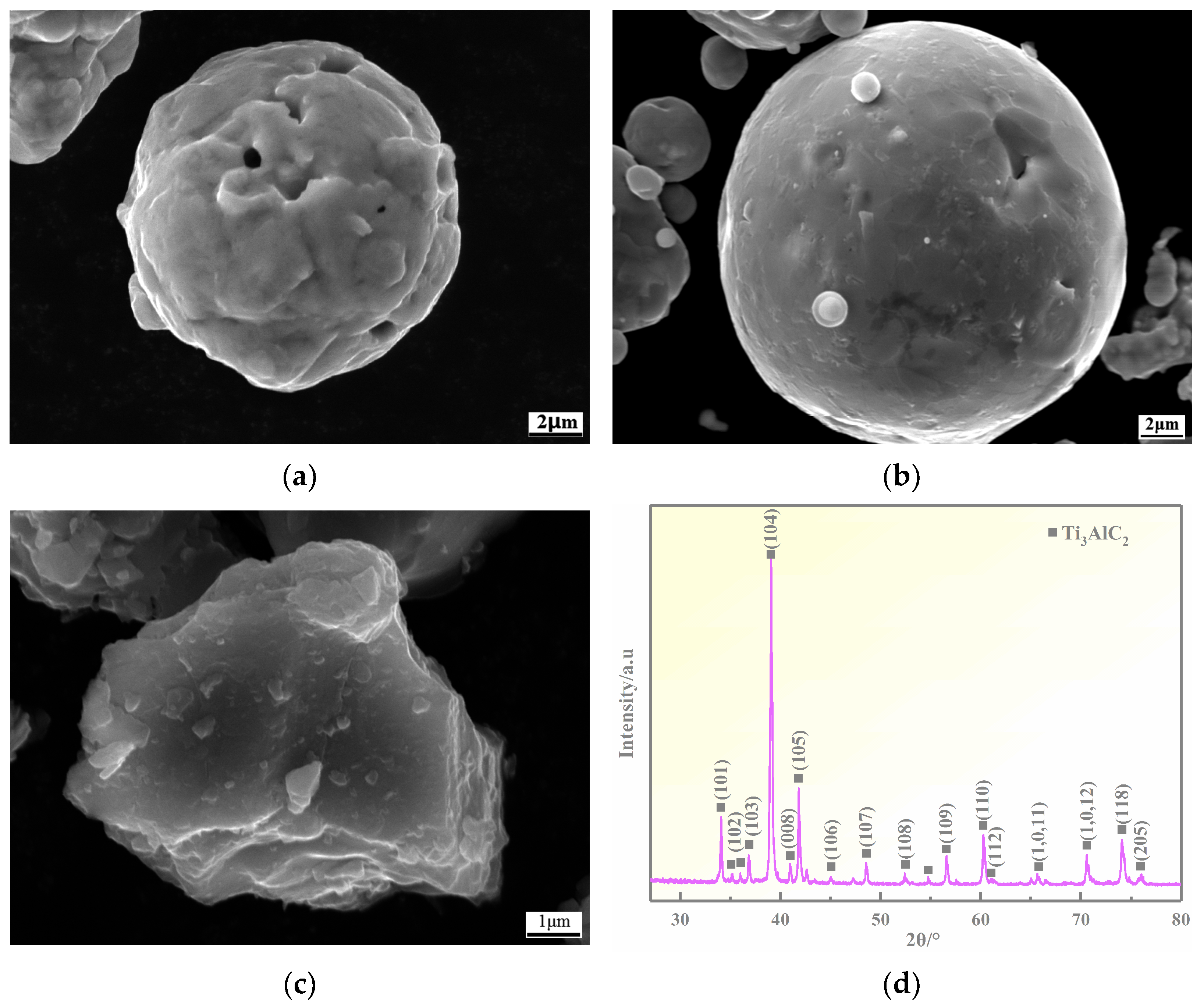
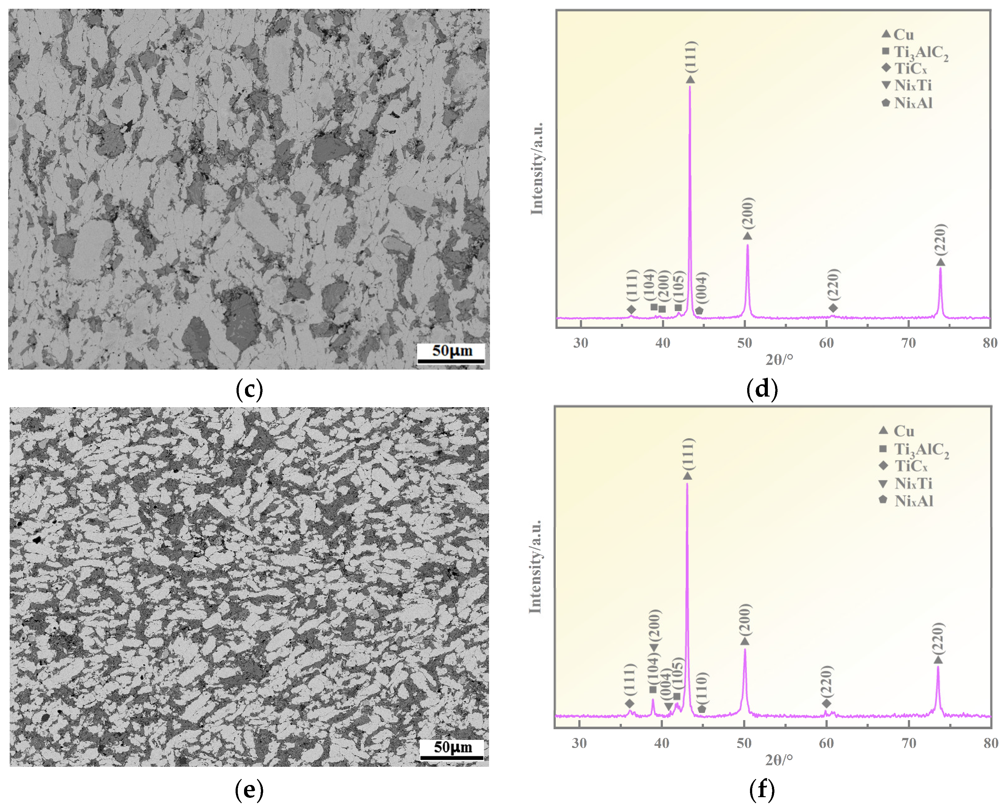
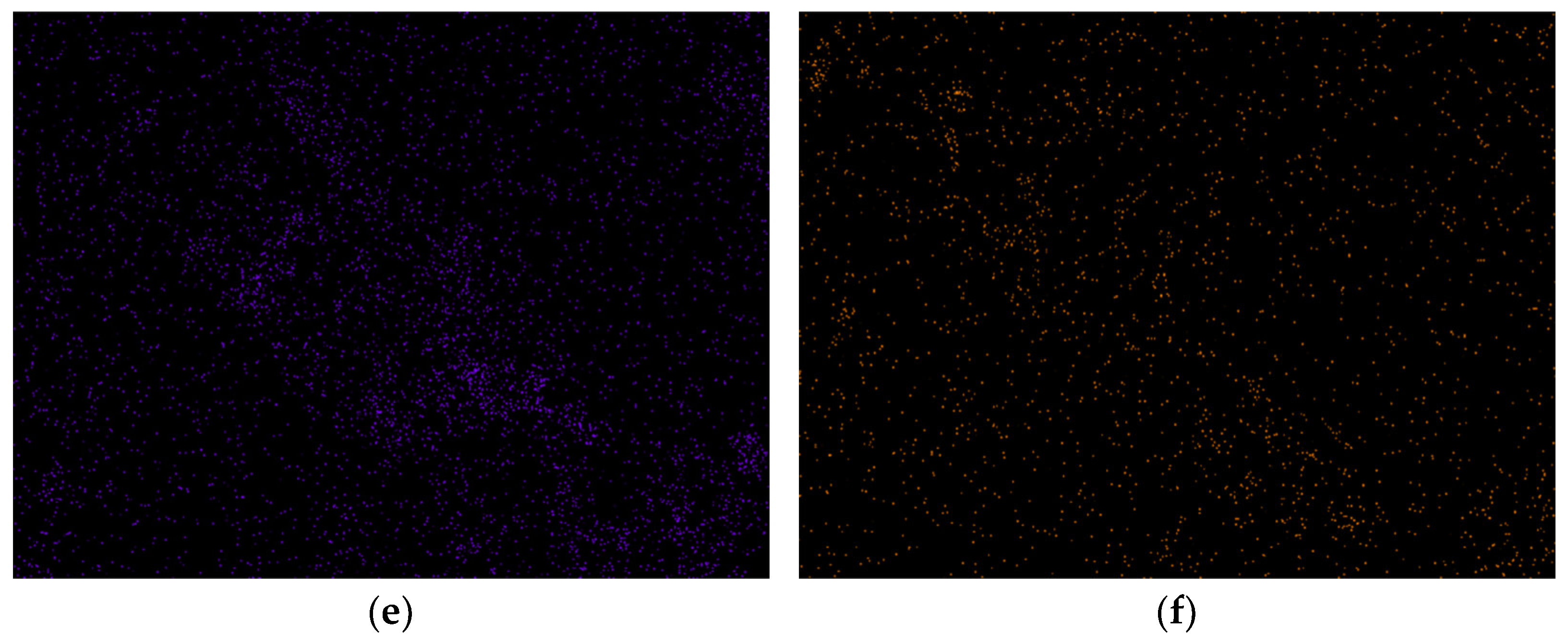
3.1. Microstructure Analyses

Figure 2 shows the SEM morphologies of Ni-Al10, Ni-Al30, and Ni-Al50 composites, respectively. In the SEM images, the light grey phase corresponds to the copper matrix, while the dark grey particles represent the Ti3AlC2 phase. The Ti3AlC2 particles can be clearly observed distributed on the copper matrix. In Figure 2a, where the volume fraction of Ti3AlC2 is 10%, the Ti3AlC2 particles are dispersed on the Cu matrix. Some Ti3AlC2 particles detach from the matrix, forming fine defects in the SEM image. However, the number and volume of defects are reduced compared to the Cu-Ti3AlC2 composites shown in Figure 2a. This indicates an improvement in the interfacial bonding strength. The XRD results in Figure 2b confirm the formation of TiCx resulting from the decomposition of Ti3AlC2. As the volume fraction of Ti3AlC2 is increased to 30% in Figure 2c, the Ti3AlC2 particles are distributed continuously in chunks on the matrix. The number and volume of defects are significantly reduced compared to the Cu-Ti3AlC2 composites shown in Figure 2c, further enhancing the interfacial bonding strength. The XRD results in Figure 2d,f reveal the presence of NixTi and NixAl in the microstructure, which are a result of adding an Ni element to the composites. When the volume fraction of Ti3AlC2 is increased to 50% in Figure 2e, the Ti3AlC2 particles form a continuous network pattern on the matrix. Fine dispersed defects can be observed in the SEM image, but they are significantly fewer compared to the Cu-Ti3AlC2 composites. This indicates a significant improvement in interfacial bonding strength. Although defects still exist after the addition of the Ni element alloying process, their number and volume are significantly reduced.
The XRD patterns of the Al10, Al30, and Al50 composites are shown in Figure 3. In the XRD patterns of the Al10 and Al30 composites (Figure 3b,d), the phases detected are Cu, Ti3AlC2, and TiCx. The presence of the TiCx peak is attributed to the reaction of Cu with Ti3AlC2 particles and the diffusion of Al atoms into the matrix, leading to the formation of TiCx. In the XRD pattern of the Al50 composite (Figure 3f), the phase analysis based on peak detection includes Cu, Ti3AlC2, TiCx, and AlxTi. The appearance of TiCx is similar to that in the Al10 composite. The formation of the AlxTi phase is attributed to the reaction between Al and Ti in the Ti3AlC2 particles at high temperature. Therefore, during the sintering process of Cu-Ti3AlC2 composites, the role of Ti3AlC2 particles in copper can be understood. Decompositions occur in the lower part of Cu, leading to the formation of TiCx as Al atoms diffuse into the matrix. When the volume fraction of Ti3AlC2 reaches 50%, the reaction between Al and Ti within Ti3AlC2 particles results in the formation of the AlxTi phase.
The surface EDS mapping analysis of Ni-Al10, Ni-Al30, and Ni-Al50 composites is shown in Figure 4, respectively. As shown in the images at high magnification, there is still porosity in Cu-Ni-Ti3AlC2 composites, but in comparison to the Cu- Ti3AlC2 composite, the porosity has been alleviated. In the surface EDS mapping results, a Cu element is indicated by blue, a Ti element is indicated by green, an Ni element is indicated by black, and an Al element is indicated by yellow. In the EDS spectrum of an Ni-Al10 composite (Figure 4b), Cu is mainly found in the matrix, and a small amount is diffusing into Ti3AlC2. Ni is found in both the reinforcement phase and the matrix, Ti is mainly found in the reinforcement phase Ti3AlC2, and Al is mainly found in the reinforcement phase Ti3AlC2. It is more prominently found in the phase boundary, and a small amount is diffusing into the matrix. In the EDS spectrum of the Ni-Al30 composite (Figure 4d), Cu is mainly found in the matrix, partially diffusing into Ti3AlC2, Ti is mainly found in the reinforcement phase Ti3AlC2, and Al is concentrated at the phase boundary and partially diffusing into the matrix. In the EDS spectrum of the Ni-Al50 composite (Figure 4f), it can be seen that in comparison to the Ni-Al10 and Ni-Al30 composites, Cu is found to a greater extent in the reinforcement phase, and Al is diffusing more into the matrix, which is mainly found at the phase interface. The Ni element is more prominently found in the matrix. It can be concluded that after the addition of Ni element alloying, as the volume fraction of Ti3AlC2 particles increases from 10% to 30% and then to 50%, Cu is mainly found in the matrix. The degree of diffusion to the reinforcement phase gradually increases, and Ti is mainly found in the reinforcement phase. The Al diffusion degree into the matrix was found to increase with the increase in the content of the reinforcement phase.
The surface EDS mapping analysis of the Ni-Al10, Ni-Al30, and Ni-Al50 composites is shown in Figure 4. At high magnification, it is evident that there is still some porosity present in the Cu-Ni-Ti3AlC2 composites. However, compared to the Cu-Ti3AlC2 composite, the porosity has been alleviated. In the surface EDS mapping results, different elements are represented by different colors: Cu (blue), Ti (green), Ni (black), and Al (yellow). In the EDS spectrum of the Ni-Al10 composite (Figure 4b), Cu is primarily found in the matrix, with a small amount diffusing into Ti3AlC2. Ni is detected in both the reinforcement phase and the matrix, while Ti is mainly found in the reinforcement phase Ti3AlC2. Al is mainly concentrated in the reinforcement phase Ti3AlC2, particularly at the phase boundary, with a small amount diffusing into the matrix. In the EDS spectrum of the Ni-Al30 composite (Figure 4d), Cu is mainly detected in the matrix, partially diffusing into Ti3AlC2. Ti is predominantly found in the reinforcement phase Ti3AlC2, and Al is concentrated at the phase boundary, partially diffusing into the matrix. In the EDS spectrum of the Ni-Al50 composite (Figure 4f), compared to the Ni-Al10 and Ni-Al30 composites, Cu is more prominently found in the reinforcement phase. Al has a greater diffusion into the matrix, primarily located at the phase interface. The Ni element is more abundant in the matrix. In conclusion, with the addition of Ni element alloying, as the volume fraction of Ti3AlC2 particles increases from 10% to 30% and then to 50%, Cu is primarily found in the matrix, with an increasing degree of diffusion to the reinforcement phase. Ti is mainly detected in the reinforcement phase, while the diffusion of Al into the matrix increases as the content of the reinforcement phase increases.

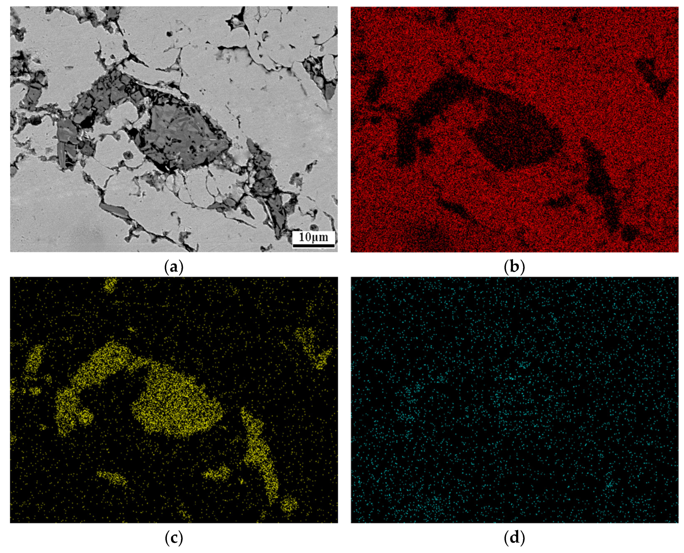
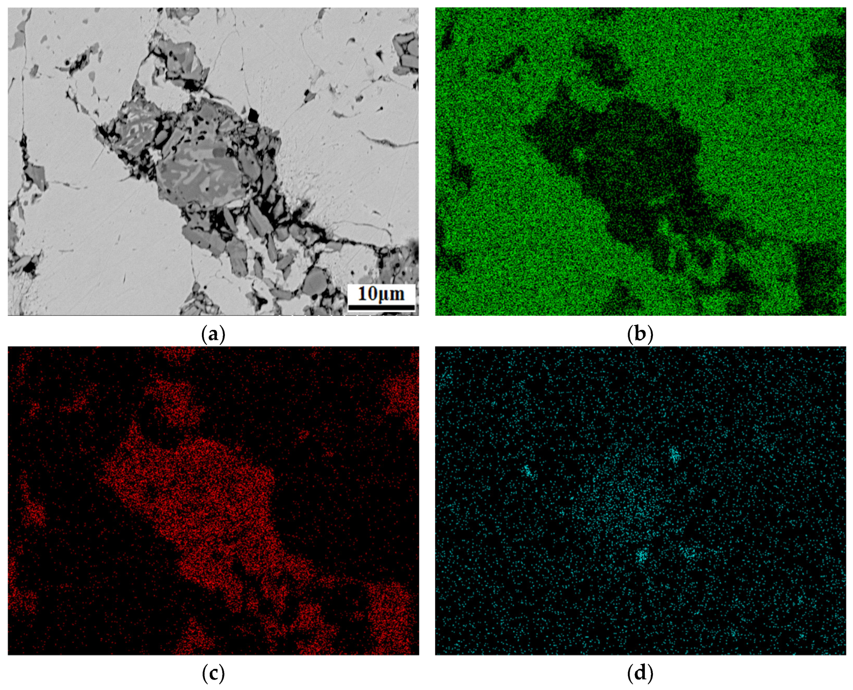
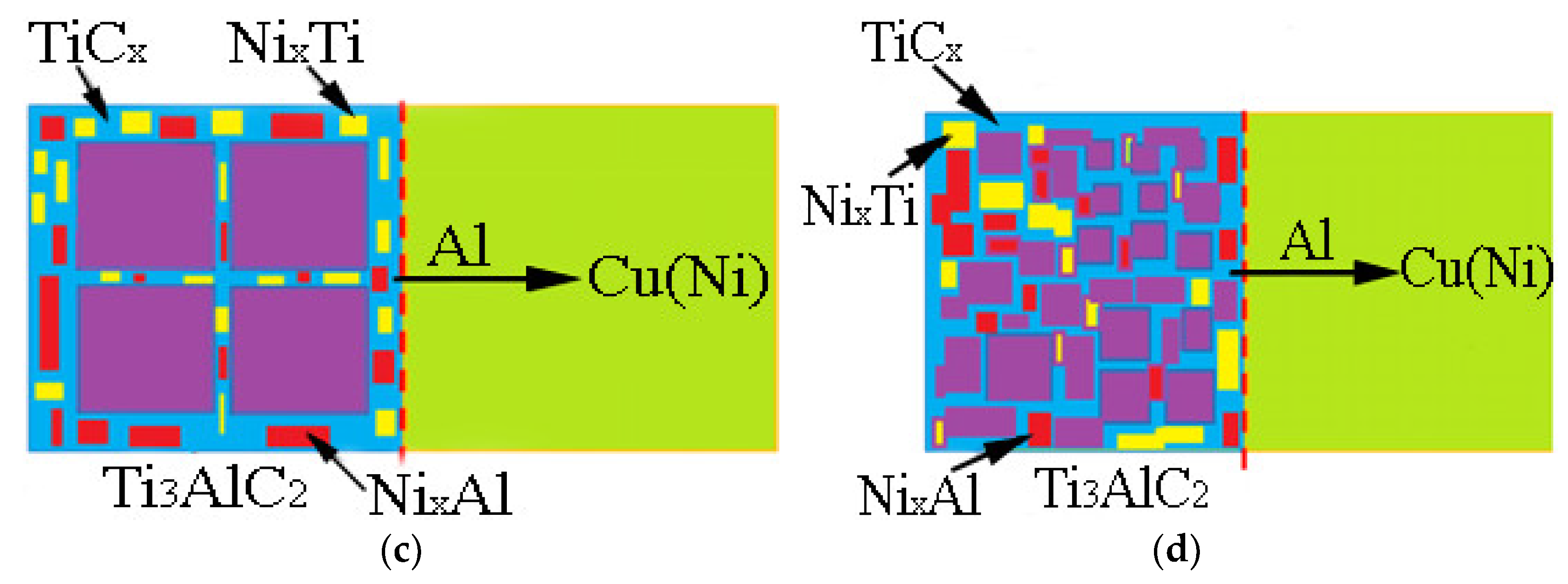
3.2. Ti3AlC2 Reinforcement Phase and the Interface

Upon further magnification of the microstructure of the composites, it was observed that the Ti3AlC2 reinforcement phase exhibited fractures and a loose state. In order to understand this phenomenon, EDS analyses specifically targeting the Ti3AlC2 particles were performed for the Ni-Al10, Ni-Al30, and Ni-Al50 composites. The results of these analyses are presented in Figure 5, Figure 6, Figure 7, and Figure 8, respectively. Examining the Ni-Al10 composite in Figure 5, it is apparent that the Ti3AlC2 reinforcement phase is not in the form of complete particles. Furthermore, there is no apparent transition layer observed between the Ti3AlC2 particles and the matrix. Interestingly, new phases were detected within the Ti3AlC2 particles. The Cu element was predominantly distributed in the matrix, with only a minor amount of diffusion into the reinforcement phase. The Ti element exhibited a mainly concentrated distribution in the reinforcement phase, but a small amount was diffusing into the matrix as well. In contrast, it was observed that the Al element had diffused extensively, resulting in a significant presence within the matrix. The Ni element, on the other hand, was not only entirely dissolved in the Cu matrix but also dispersed throughout the reinforcement phase. This analysis provides insights into the microstructure of the Ni-Al10 composite and highlights the complex distribution and interaction of various elements within the composite system.
In the Ni-Al10 composite, EDS analyses were conducted at three specific points represented as point 1 and 2 in the reinforcement phase, and point 3 in the matrix, as shown in Figure 6. The composition of the materials was determined by obtaining the mass percentage and atomic percentage of elements C, Al, Ni, Ti, and Cu, as summarized in Table 2. At point 3, located in the Cu matrix, the atomic percentages of Cu, C, Al, and Ni are 70.25%, 27.9%, 1.36%, and 1.29%, respectively. It is observed that the content of Al in the reinforcement phase is higher than that in the matrix. However, the complete prevention of Ti3AlC2 decomposition by Ni has not been achieved, and the diffusion of the Al element into the matrix has not been completely inhibited. Point 2 is situated in the reinforcement phase. The atomic percentages of Ti and Ni are 20.82% and 5.46%, respectively, with a carbon content of 29.33%. These results indicate that Ni has diffused into the reinforcement phase, corroborating the earlier analyses. The high content of Ti suggests that its diffusion is minimal, while the Al and Cu contents are 10.29% and 34.11%, respectively. XRD analysis confirms the absence of an AlxTi phase at point 2, implying that the phase is likely to be NixAl and NixTi compounds. At point 1, located in the reinforcement phase, the atomic percentage of Ti is higher (36.32%), while the Al content is lower (1.12%). Conversely, the Cu and C contents are higher (21.95% and 40.62%, respectively). These observations suggest that the phase at point 1 is composed of NixTi compounds. These EDS results provide further insights into the elemental compositions at different points within the Ni-Al10 composite, shedding light on the distribution and interactions of elements in the composite system.
In conclusion, the EDS point analysis of the Ti3AlC2 particles has provided valuable insights. It has been observed that Cu has diffused into the reinforcement phase, while Ni has diffused into the matrix of the reinforcement phase [27]. Additionally, Ti has shown a degree of diffusion into the matrix, while C has exhibited significant diffusion intensity. The content of Al is relatively low in the Cu matrix but higher in the reinforcement phase. These findings suggest that the presence of Ni delays the diffusion of Al from the Ti3AlC2 particles.
In the Ni-Al30 composites, as observed in Figure 7, the reinforcement phase exhibits a loose structure, with the presence of new phases within the Ti3AlC2 particles and between the reinforcement phase and the matrix. Cu is predominantly distributed in the matrix, with only a small amount diffusing into the reinforcement phase. In contrast, Ti is mainly distributed in the reinforcement phase, with a minor diffusion into the matrix. While the diffusion of the Al element to the matrix is still significant compared to the Ni-Al10 composite, it is reduced in comparison. Notably, the Ni element is detected in both the matrix and the reinforcement phase. These observations provide insights into the distribution and diffusion behavior of different elements in the Ni-Al30 composites.
In the Ni-Al50 composites, as depicted in Figure 8, the reinforcing phase also demonstrates a loose structure, accompanied by the presence of new phases within the Ti3AlC2 particles and at the boundary between the reinforcement and the matrix. The distribution of Cu is primarily concentrated in the matrix, with only a minor amount diffusing into the reinforcement phase. Similarly, Ti is predominantly distributed in the reinforcement phase, with a small diffusion into the matrix. Although the diffusion of the Al element into the matrix is still significant, it is relatively lower compared to the Ni-Al10 composite. Interestingly, the Ni element is detected in both the matrix and the reinforcement phase. Furthermore, the porosity of the composites, which represents the relative density, was measured using Archimedes’ principle. The porosity values for Ni-Al10, Ni-Al30, and Ni-Al50 composites are 10.2%, 8.5%, and 5.5%, respectively. In comparison, the porosity values for Al10, Al30, and Al50 are 14.2%, 12.7%, and 10.6%, respectively. These measurements provide information about the relative densities and porosities of the different composite samples.
To investigate the interface between the reinforcement phase and the matrix in the Cu-Ni-Ti3AlC2 composites, as well as the phase composition of the Ti3AlC2 particles, an EDS line test was conducted on the cross section of the particle and the Cu matrix in the Ni-Al10 composite. The microstructure was further magnified for analysis, and the results are presented in Figure 9. According to the analysis, Cu is primarily distributed in the matrix, with a smaller amount present in the reinforcement phase. The content of Cu decreases sharply at the interface between the reinforcement phase and the matrix. On the other hand, Ti is predominantly distributed in the reinforcement phase, with a negligible quantity in the matrix. The content of Ti drastically drops at the interface between the matrix and the reinforcement phase, exhibiting a decrease at one point and an increase at two other points. Al is found in both the matrix and the reinforcement phase, indicating ongoing decomposition of Ti3AlC2 particles and infiltration of Al elements into the Cu matrix. The content of Al reaches a peak at one point and exhibits valleys at two other points. Additionally, Ni elements are detected in both the reinforcement phase and the matrix. The content of Al element is greater at point 1, while the content of Ti element is higher at points 1 and 2. Preliminary analysis suggests that the phase at point 1 corresponds to the NixAl compound, while the phase at point 2 corresponds to the NixTi compound. These findings provide initial insights into the phase composition at different points within the Ni-Al10 composite, revealing the distribution of various elements and suggesting the presence of specific compounds at specific locations.

3.3. Mechanical Properties

Figure 10a illustrates a comparison of the microhardness between Cu-Ni-Ti3AlC2 and Cu-Ti3AlC2 composites. The microhardness values of both composites exhibit an increase as the volume fraction of Ti3AlC2 increases. This can be attributed to the diffusion of the Al element, which leads to an increase in the content of TiCx. Notably, the hardness of both TiCx and Ti3AlC2 is higher than that of the Cu matrix. Additionally, when the Ti3AlC2 content is 10%, the inclusion of Ni results in an increase in hardness. This is because the addition of Ni strengthens the Cu matrix, and Ni exhibits fewer reactions with the Al and Ti elements, causing a slight elevation in hardness. However, the situation changes when the Ti3AlC2 content reaches 30% and 50%. In these cases, the introduction of Ni actually reduces the hardness of the composite materials.
Figure 10b presents a comparison of the flexural strength between Cu-Ni-Ti3AlC2 and Cu-Ti3AlC2 composites. The flexural strength of both composites demonstrates a decrease as the volume fraction of the reinforcement phase Ti3AlC2 increases. This reduction can be attributed to the poor wettability between the reinforcement phase and the matrix, leading to a weakening of the bonding interface. As a consequence, the loss of the reinforcement phase contributes to the formation of pores. Under applied loads, stress concentration accelerates crack propagation, leading to a deterioration in performance. The effect of Ni alloying on bending strength varies. The Ni element can contribute to solution strengthening, and an increased nickel content generally enhances the strength. For the 10% Cu-Ni-Ti3AlC2 composite, the flexural strength decreases significantly from 213.31 MPa to 170.15 MPa. However, the flexural strength of the 30% and 50% Ni composites increases considerably to 92.69 MPa and 84.23 MPa, respectively. Specifically, the flexural strength of Cu-Ni-Ti3AlC2 composites decreases when the Ti3AlC2 content is 10%. This is due to the addition of Ni, which inhibits Al diffusion and reduces the content of TiCx. As TiCx possesses better mechanical properties than Ti3AlC2, the flexural strength is reduced. On the other hand, the addition of 30% and 50% Ti3AlC2 forms a new phase on the grain boundary of the Cu-Ni-Ti3AlC2 composite. This new phase effectively connects the Ti3AlC2 particles and the Cu matrix, improving the interface bonding strength of the reinforcement phase. Consequently, this reduces the volume and number of pores, ultimately enhancing the flexural strength. The most significant increase in flexural strength is observed when the Ti3AlC2 content is 50%, where it increases from 33.78 MPa to 84.23 MPa upon the inclusion of the Ni element.

3.4. Mechanism of Anti-Decomposition of Ni Element

The mechanism behind the anti-decomposition effect of the Ni element in Cu-Ni-Ti3AlC2 composites can be elucidated through the analysis of surface morphology, phase composition, and energy spectrum, as presented in Figure 11. Figure 11a illustrates the initial stage, where the Ni element is solely dissolved in the Cu matrix. As the Al and Ti elements diffuse into the Cu matrix, the Cu and Ni elements migrate toward the Ti3AlC2 reinforcement phase. Simultaneously, the Al element spreads to the grain boundary, resulting in the formation of a Cu(Al) solid solution within the matrix. At the interface, the reinforcement phase undergoes the formation of TiCx. Furthermore, Ni, Al, and Ti elements that penetrate the reinforcement phase form NixAl and NixTi compounds on its grain boundary, as demonstrated in Figure 11c. This process effectively hinders the diffusion of Al elements and strengthens the binding force at the interface.

4. Conclusions

Based on the study, the following conclusions were drawn regarding the Cu-Ni-Ti3AlC2 composites:
  • The addition of Ni elements results in a microstructure consisting of Ti3AlC2, TiCx, NixAl, NixTi, and a Cu(Ni) matrix in the Cu-Ni-Ti3AlC2 composites. As the volume fraction of Ti3AlC2 particles increases, the morphology changes from a finely dispersed reinforcement phase to a continuous network. This leads to a reduction in the number and volume of pores compared to Cu-Ti3AlC2 composites. This reduction is particularly significant when the volume fraction of Ti3AlC2 exceeds 50%.
  • The formation of NixAl and NixTi compounds at the grain boundary of the reinforcement phase, after the addition of Ni elements, restricts the diffusion of Al elements. This mechanism contributes to the anti-decomposition effect of Ni in Cu-Ni-Ti3AlC2 composites.
  • The addition of Ni elements improves the mechanical properties of the composites. In terms of hardness, composites with low Ti3AlC2 content experience enhanced hardness, while those with high Ti3AlC2 content may exhibit a slight decrease. Regarding bending strength, composites with low Ti3AlC2 content show a decrease, while those with high content show a significant improvement. Notably, composites with a Ti3AlC2 content of 50% experience a significant increase in flexural strength, rising from 33.78 MPa to 84.23 MPa upon the addition of Ni elements.
Overall, the results suggest that the addition of Ni elements in Cu-Ni-Ti3AlC2 composites leads to improved microstructural characteristics, enhanced mechanical properties, and a modification effect, which can be beneficial for various applications requiring high strength and stability.

Author Contributions

Y.W.: conceptualization, methodology, investigation, formal analysis, writing—original draft. L.X.: investigation, funding acquisition. X.L.: formal analysis, conceptualization, writing—editing. All authors have read and agreed to the published version of the manuscript.

Funding

This research was funded by the Open Fund of the National Joint Engineering Research Centre for Abrasion Control and Moulding of Metal Materials, grant number HKDNM202103.

Institutional Review Board Statement

Not applicable.

Informed Consent Statement

Not applicable.

Data Availability Statement

The data used to support the findings of this study are available from the corresponding author upon request.

Acknowledgments

We thank Zijun Ren at the Instrument Analysis Centre of Xi’an Jiaotong University for their assistance with SEM analyses.

Conflicts of Interest

The authors declare no conflict of interest.

References

  1. Zhang, J.; He, L.; Zhou, Y. Highly conductive and strengthened copper matrix composite reinforced by Zr2Al3C4 particulates. Scr. Mater. 2009, 60, 976–979. [Google Scholar] [CrossRef]
  2. Wang, Y.; Gao, Y.; Li, Y.; Zhai, W.; Sun, L.; Zhang, C. Review on preparation and application of copper-steel bimetal composites. Emerg. Mater. Res. 2019, 8, 538–551. [Google Scholar] [CrossRef]
  3. Li, H.; Liu, Y.; Zheng, B.; Wang, S.; Yi, Y.; Zhang, Y.; Li, W. On the tribological behaviors of Cu matrix composites with different Cu-coated graphite content. J. Mater. Res. Technol. 2023, 25, 83–94. [Google Scholar] [CrossRef]
  4. Kumar, N.; Kumaran, S.; Kumaraswamidhas, L. High temperature investigation on EDM process of Al2618 alloy reinforced with Si3N4, AlN and ZrB2 in-situ composites. J. Alloys Compd. 2016, 663, 755–768. [Google Scholar] [CrossRef]
  5. Moazami-Goudarzi, M.; Akhlaghi, F. Wear behavior of Al5252 alloy reinforced with micrometric and nanometric SiC particles. Tribol. Int. 2016, 102, 28–37. [Google Scholar] [CrossRef]
  6. Manory, R. A novel electrical contact material with improved self-lubrication for railway current collectors. Wear 2001, 249, 626–636. [Google Scholar]
  7. Tang, Y.; Liu, H.; Zhao, H.; Liu, L.; Wu, Y. Friction and wear properties of copper matrix composites reinforced with short carbon fibers. Mater. Des. 2008, 29, 257–261. [Google Scholar] [CrossRef]
  8. Kumar, N.; Gautam, G.; Gautam, R.; Mohan, A.; Mohan, S. Wear, friction and profilometer studies of in-situ AA5052/ZrB2 composites. Tribol. Int. 2016, 97, 313–326. [Google Scholar] [CrossRef]
  9. Gu, D.; Shen, Y. Influence of reinforcement weight fraction on microstructure and properties of submicron WC–Cop/Cu bulk MMCs prepared by direct laser sintering. J. Alloys Compd. 2007, 431, 112–120. [Google Scholar] [CrossRef]
  10. Wang, Y.; Gao, Y.; Li, Y.; Zhang, C.; Sun, L.; Zhai, W. Research on nickel modified graphite/Cu composites interface. Surf. Coat. Technol. 2017, 328, 70–79. [Google Scholar] [CrossRef]
  11. Wang, Y.; Gao, Y.; Li, Y.; Li, M.; Sun, L.; Zhai, W.; Li, K. Research on synergistic lubrication effect of silver modified Cu–Ni-graphite composite. Wear 2020, 444–445, 203140. [Google Scholar] [CrossRef]
  12. Rajkovic, V. Dispersion hardened Cu-Al2O3 produced by high energy milling. Int. J. Powder Metall. 2000, 36, 45–49. [Google Scholar]
  13. Sun, D.; Jiang, X.; Sun, H.; Song, T.; Luo, Z. Microstructure and mechanical properties of Cu-ZTA cermet prepared by vacuum hot pressing sintering. Mater. Res. Exp. 2020, 7, 026530. [Google Scholar] [CrossRef]
  14. Deshpande, P.; Lin, R. Wear resistance of WC particle reinforced copper matrix composites and the effect of porosity. Mater. Sci. Eng. A 2006, 418, 137–145. [Google Scholar] [CrossRef]
  15. Deshpande, P.; Li, J.; Lin, R. Infrared processed Cu composites reinforced with WC particles. Mater. Sci. Eng. A 2006, 429, 58–65. [Google Scholar] [CrossRef]
  16. Froumin, N.; Frage, N.; Aizenshtein, M.; Dariel, M. Ceramic-metal interaction and wetting phenomena in the B4C/Cu system. J. Eur. Ceram. Soc. 2003, 23, 2821–2828. [Google Scholar] [CrossRef]
  17. Zarrinfar, N.; Shipway, P.; Kennedy, A.; Saidi, A. Carbide stoichiometry in TiCx and Cu-TiCx produced by self-propagating high-temperature synthesis. Scr. Mater. 2002, 46, 121–126. [Google Scholar] [CrossRef]
  18. Zarrinfar, N.; Kennedy, A.; Shipway, P. Reaction synthesis of Cu-TiCx master-alloys for the production of copper-matrix composites. Scr. Mater. 2004, 50, 949–952. [Google Scholar] [CrossRef]
  19. Rado, C.; Drevet, B.; Eustathopoulos, N. The role of compound formation in reactive wetting: The Cu/SiC system. Acta Mater. 2000, 48, 4483–4491. [Google Scholar] [CrossRef]
  20. Kim, J.H.; Yun, J.H.; Park, Y.H.; Cho, K.M.; Choi, I.D.; Park, I.M. Manufacturing of Cu-TiB2 composites by turbulent in situ mixing process. Mater. Sci. Eng. A 2007, 449–451, 1018–1021. [Google Scholar] [CrossRef]
  21. Wang, Y.; Gao, Y.; Takahashi, J.; Wan, Y.; Li, M.; Xiao, B.; Zhang, Y.; He, X. Investigation of modification of Cu-Ni-graphite composite by silver. Mater. Chem. Phys. 2019, 239, 121990. [Google Scholar] [CrossRef]
  22. Wang, Y.; Gao, Y.; Takahashi, J.; Wan, Y.; Xiao, B.; Zhang, Y.; He, X.; Li, J. Titanium-modified graphite reinforced Cu-Ni composite by multi-arc ion plating technology. Vacuum 2019, 168, 108829. [Google Scholar] [CrossRef]
  23. Eklund, P.; Beckers, M.; Jansson, U.; Högberg, H.; Hultman, L. The Mn+1AXn phases: Materials science and thin-film processing. Thin Solid Film. 2010, 518, 1851–1878. [Google Scholar] [CrossRef] [Green Version]
  24. Sun, Z. Progress in research and development on MAX phases: A family of layered ternary compounds. Int. Mater. Rev. 2011, 56, 143–166. [Google Scholar] [CrossRef]
  25. Hu, L.; Kothalkar, A.; Proust, G.; Karaman, I.; Radovic, M. Fabrication and characterization of NiTi/Ti3SiC2 and NiTi/Ti2AlC composites. J. Alloys Compd. 2014, 610, 635–644. [Google Scholar] [CrossRef]
  26. Mahesh, K.; Balanand, S.; Raimond, R.; Mohamed, A.P.; Ananthakumar, S. Polyaryletherketone polymer nanocomposite engineered with nanolaminated Ti3SiC2 ceramic fillers. Mater. Des. 2014, 63, 360–367. [Google Scholar] [CrossRef]
  27. Su, J.; Liu, Y.; Luo, F.; Zhou, W.; Zhu, D.; Li, Z. Enhanced mechanical, dielectric and microwave absorption properties of cordierite based ceramics by adding Ti3SiC2 powders. J. Alloys Compd. 2015, 619, 854–860. [Google Scholar]
  28. Zhou, Y.; Wang, X.; Sun, Z.; Chen, S. Electronic and structural properties of the layered ternary carbide Ti3AlC2. J. Mater. Chem. 2001, 11, 2335–2339. [Google Scholar] [CrossRef]
  29. Huang, Z.; Bonneville, J.; Zhai, H.; Gauthier-Brunet, V.; Dubois, S. Microstructural characterization and compression properties of TiC0.61/Cu(Al) composite synthesized from Cu and Ti3AlC2 powders. J. Alloys Compd. 2014, 602, 53–57. [Google Scholar] [CrossRef]
  30. Zhang, J.; Wang, J.; Zhou, Y. Structure stability of TiAlC in Cu and microstructure evolution of Cu-TiAlC composites. Acta Mater. 2007, 55, 4381–4390. [Google Scholar] [CrossRef]
  31. Zhang, J.; Zhou, Y. Microstructure, mechanical, and electrical properties of Cu-Ti3AlC2 and in-situ Cu-TiCx composites. J. Mater. Res. 2008, 23, 924–932. [Google Scholar] [CrossRef]
  32. Wang, W.; Zhai, H.; Chen, L.; Huang, Z.; Bei, G.; Greil, P. Preparation and mechanical properties of TiCx-(NiCu)3Al-CuNi2Ti-Ni hybrid composites by reactive pressureless sintering pre-alloyed Cu/Ti3AlC2, and Ni as precursor. Mater. Sci. Eng. A 2016, 670, 351–356. [Google Scholar] [CrossRef]
  33. Wang, W.; Zhai, H.; Chen, L.; Zhou, Y.; Huang, Z.; Bei, G.; Greil, P. Sintering and properties of mechanical alloyed Ti3AlC2-Cu composites. Mater. Sci. Eng. A 2017, 685, 154–158. [Google Scholar] [CrossRef]
  34. Wang, W.J.; Gauthier-Brunet, V.; Bei, G.P.; Laplanche, G.; Bonneville, J.; Joulain, A.; Dubois, S. Powder metallurgy processing and compressive properties of Ti3AlC2/Al composites. Mater. Sci. Eng. A 2011, 530, 168–173. [Google Scholar] [CrossRef]
  35. Ho, J.; Hamdeh, H.; Barsoum, M.; El-Raghy, T. Low temperature heat capacities of Ti3Al1.1C1.8, Ti4AlN3, and Ti3SiC2. J. Appl. Phys. 1999, 86, 3609–3611. [Google Scholar] [CrossRef]
  36. Wang, Y.; Gao, Y. Effect of Ti in inhibiting the decomposition of Ti3SiC2 in copper matrix composites. Foundry Technol. 2022, 43, 410–416. [Google Scholar]
Figure 1. SEM images and XRD of the raw materials. (a) Cu powder; (b) Ni powder; (c) Ti3AlC2 powder; (d) XRD results of Ti3AlC2.
Coatings 13 01414 g001
Figure 2. SEM and XRD results of the Cu-Ni-Ti3AlC2 composites. (a) SEM image of Ni-Al10; (b) XRD results of the Ni-Al10; (c) SEM image of Ni-Al30; (d) XRD results of the Ni-Al30; (e) SEM image of Ni-Al50; (f) XRD results of the Ni-Al50.
Coatings 13 01414 g002aCoatings 13 01414 g002b
Figure 3. SEM and XRD results of the Cu-Ti3AlC2 composites. (a) SEM image of Al10; (b) XRD results of the Al10; (c) SEM image of Al30; (d) XRD results of the Al30; (e) SEM image of Al50; (f) XRD results of the Al50.
Coatings 13 01414 g003aCoatings 13 01414 g003b
Figure 4. High magnification SEM and EDS mapping results of the Cu-Ni-Ti3AlC2 composites. (a) SEM image of Ni-Al10; (b) EDS results of the Ni-Al10; (c) SEM image of Ni-Al30; (d) EDS results of the Ni-Al30; (e) SEM image of Ni-Al50; (f) EDS results of the Ni-Al50.
Coatings 13 01414 g004
Figure 5. SEM and EDS mapping results of the Ti3AlC2 particle in Ni-Al10. (a) SEM image of the Ti3AlC2 particle in Ni-Al10; (b) EDS results of Cu element; (c) Ti element; (d) Al element; (e) C element; (f) Ni element.
Coatings 13 01414 g005aCoatings 13 01414 g005b
Figure 6. High magnification SEM of the Ti3AlC2 particle in Ni-Al10 (1, 2, 3 points are test area).
Coatings 13 01414 g006
Figure 7. SEM and EDS mapping results of the Ti3AlC2 particle in Ni-Al30. (a) SEM image of the Ti3AlC2 particle in Ni-Al30; (b) EDS results of Cu element; (c) Ti element; (d) Al element; (e) C element; (f) Ni element.
Coatings 13 01414 g007aCoatings 13 01414 g007b
Figure 8. SEM and EDS mapping results of the Ti3AlC2 particle in Ni-Al50. (a) SEM image of the Ti3AlC2 particle in Ni-Al50; (b) EDS results of Cu element; (c) Ti element; (d) Al element; (e) C element; (f) Ni element.
Coatings 13 01414 g008aCoatings 13 01414 g008b
Figure 9. SEM and EDS line results of the interface. (a) SEM at low magnification; (b) SEM at low magnification (1, 2 points are test area); (c) EDS line results.
Coatings 13 01414 g009
Figure 10. Mechanical properties. (a) Hardness; (b) Flexural strength.
Coatings 13 01414 g010
Figure 11. The mechanism of anti-decomposition of Ni element in Cu-Ni-Ti3AlC2 composites. (a) Initial stage; (b) Diffusion stage; (c) Reaction stage; (d) Final stage.
Coatings 13 01414 g011aCoatings 13 01414 g011b
Table 1. Chemical composition of Cu-based self-lubricating materials.
SampleTi3AlC2/Vol.%Ni/wt.%Cu/wt.%
Ni-Al10108Bal.
Ni-Al30308Bal.
Ni-Al50508Bal.
Al1010/Bal.
Al3030/Bal.
Al5050/Bal.
Table 2. Chemical composition of EDS point results in Figure 6.
PointCAlTiNiCu
at.%wt.%at.%wt.%at.%wt.%at.%wt.%at.%wt.%
140.6213.361.120.8236.327.63//21.9538.19
229.338.5610.296.7520.824.235.467.7934.1152.67
327.906.641.360.75//1.291.5570.2591.70
Disclaimer/Publisher’s Note: The statements, opinions and data contained in all publications are solely those of the individual author(s) and contributor(s) and not of MDPI and/or the editor(s). MDPI and/or the editor(s) disclaim responsibility for any injury to people or property resulting from any ideas, methods, instructions or products referred to in the content.

