Article

Influence of Cu Substitution on the Properties of Hydroxyapatite Targets and Deposited Coatings

1
Laboratory of Physics of Nanostructured Biocomposites, Institute of Strength Physics and Materials Science, Siberian Branch of Russian Academy of Sciences, 634055 Tomsk, Russia
2
Research School of High-Energy Physics, National Research Tomsk Polytechnic University, 634050 Tomsk, Russia
*
Authors to whom correspondence should be addressed.
Coatings 2023, 13(8), 1410; https://doi.org/10.3390/coatings13081410
Submission received: 30 June 2023 / Revised: 1 August 2023 / Accepted: 8 August 2023 / Published: 11 August 2023

Abstract

:
In addressing the issue of optimizing the mechanical and electrochemical properties of hydroxyapatite (CaP) materials for biomedical applications, this research explored the incorporation of copper (Cu) into the material and scrutinized its impact through various processing stages, from powders to ceramics and finally to coatings. Our investigation indicated that the integration of CuO into CaP significantly changed the lattice parameters of hydroxyapatite from manufactured powders to sintered targets, indicating a structural evolution. Simultaneously, the change in the elemental composition and Ca/P ratio was also followed by each step from manufactured powders to deposited coatings. Mechanical testing revealed an impressive increase in the hardness of coatings to a high of 37 GPa for the 0.2CuO-CaP sample, a substantial improvement when compared to 13 GPa for pure Ti. The corrosion resistance of the coatings also improved, evidenced by the decrease in corrosion current density (Icorr) from 60.2 ± 5.2 nA/cm2 for pure Ti to a lower 3.9 ± 0.5 nA/cm2 for the CaP coating. Our study has revealed that the structural, mechanical, and electrochemical properties of CaP materials can be finely adjusted through the addition of Cu, promising advances in the realm of biomedical applications. Moreover, these results hint at the potential to tune the electrophysical characteristics of CaP coatings, an avenue for future exploration.

1. Introduction

Recent advancements in the field of medical materials science have set the stage for a new era in the treatment of diseases related to the musculoskeletal system. This innovative approach harnesses the potential of regenerative medicine. It employs the use of varied implant types. Many of these implants are specifically modified to address various clinical scenarios [1,2].
The lifespan and effectiveness of these implants are largely influenced by their surface characteristics. This highlights the crucial role played by the choice of material and any subsequent modifications [3]. Notably, the material selection for these implants is not arbitrary; it is dictated by the need for mechanical compatibility with bone tissue. Therefore, materials with similar mechanical properties to bone tissue, such as metals and their alloys—including stainless steel, cobalt, titanium, zirconium, and tantalum—have been the choice of preference [4,5,6].
These selected alloys, known for their high strength and fatigue resistance, have found extensive use in the medical field. They have become integral in the fabrication of various medical devices, particularly those required for treating pathologies of the maxillofacial region and the musculoskeletal system. Titanium and its alloys have emerged as the most suitable materials for implants. Their ideal combination of mechanical and biomedical properties make them optimal for use in fields such as orthopedics, dentistry, and maxillofacial surgery [7,8,9,10]. As we move forward in this era of personalized medicine, patient-specific implants, tailor-made through the comprehensive understanding of implant materials, their surface properties and modification techniques, will likely lead to improved clinical outcomes and quicker recovery periods [11].
A significant challenge for modern healthcare is the effective prevention of bacterial infections that accompany implant surgeries. One potential method for reducing the risk of postoperative complications due to bacterial infections is to modify implant surfaces with antibacterial coatings [12,13,14,15]. Forming antibacterial coatings on implants, which would possess high strength and adequate adhesion for operation under mechanical loads, is a pertinent issue in medical materials science. Importantly, these coatings should be biocompatible and bioactive, supporting bone growth and accelerated healing. Calcium phosphate (CaP) biocoatings meet these requirements [16,17,18,19].
Hydroxyapatite (HA)-based CaP biomaterials are widely used in implantology due to their elemental composition, being close to the mineral constituent of bone tissue [20]. The production and application of HA-based CaP biocoatings with the partial replacement of Ca2+ ions in the structure by cations of other metals are of considerable interest, as substitutions in the HA structure significantly change their physicochemical and biological properties, including improved biocompatibility [21,22,23]. Various metal ions can be used for synthesizing substituted HA, with Zn and Cu being particularly noteworthy. It has been found that ions of these metals contribute to the osteogenesis processes when used in certain concentrations. They are also interesting for their antibacterial properties, which could be useful for preventing peri-implantitis—inflammation of the tissues around a previously placed implant. By replacing Ca2+ ions with Zn2+ and Cu2+ in the HA lattice through manipulating deposition parameters, it is possible to tailor coating properties such as its biological activity and antibacterial effect [19,24].
RF magnetron sputtering serves as a commonly adopted approach for depositing calcium phosphate (CaP) coatings onto implant surfaces [25,26]. This technique enables the achievement of impressive adhesion between the coating and substrate while also offering control over the properties and morphology of CaP coatings. This control is crucial given the significant mechanical strain experienced by the surfaces of implant materials during the process of implantation [18,27,28]. Regarding the formation of CaP coatings via RF magnetron sputtering, targets play a pivotal role. The configuration and dimensions of these targets are dependent on the nature of the sputtering system and can be adjusted as per the technical requirements. it is essential to note that CaPs are typically brittle; therefore, the target must boast substantial microhardness and density for its secure attachment to the cathode [29]. The creation of a target involves two primary steps: forming the target from the relevant powdered material and subsequently sintering it. The initial target formation process comprises the manufacture of a press powder (a humid mass that includes a plasticizer and the original powder of a defined chemical composition). This press powder is then subjected to hot or cold pressure in molds [30,31]. Sintering is a densification procedure where the particles of the powder interconnect under high temperatures, resulting in material hardening [32]. It is widely accepted that the key properties of single-phase ceramics are strongly associated with material densification, which considerably reduces the level of porosity [33]. However, the choice of sintering regimes for HA ceramics is constrained due to the potential for hydroxyl group loss and material degradation at high temperatures [34]. During sintering in a vacuum, HAs can decompose into calcium oxide (CaO), tricalcium phosphate (TCP), tetracalcium phosphate (TTCP), and potentially result in the formation of phosphorus oxide P2O5 [35]. Thus, the production of HA targets for RF magnetron sputtering is a complex process requiring careful control over every step. Balancing the need for high-density, defect-free ceramics with the brittle nature of CaP materials, as well as the challenges posed by sintering, means that careful material and process selection is vital. With appropriate strategies in place, however, this method could provide an efficient way to create high-quality antibacterial coatings for implants.
The synthesis of CaP powder, the prior step to target sintering, plays a vital role in the success of the desired outcome. Over the past few decades, the mechanochemical method has emerged as a popular choice for synthesizing various compounds, including HA [36,37,38]. The appeal of this method lies in its simplicity and environmental benefits, as it can perform solid-phase reactions in a solvent-free environment, reducing the likelihood of undesirable side reactions. This procedure eliminates the need for high temperatures, executing processes at room temperature and pressure. In the mechanochemical synthesis, energy is liberated from the collisions of balls in a specialized planetary mill, instigating chemical reactions. This energy release is contingent on the mill’s technical characteristics, specifically the kinetic energy of the balls, determined by the flask’s rotation speed. Consequently, HA synthesis, occurring directly within the grinding flasks, is solely possible in ball mills operating at high rotation velocities. A higher rotation speed of the flask correlates to a shorter HA synthesis duration [38].
Furthermore, the mechanochemical method enables the creation of novel HA forms and facilitates HA synthesis with different doping ions, thus expanding the scope of potential applications. It also provides avenues for fabricating more complex, multi-component systems, underscoring its versatility in the realm of materials science. As it has already been said, the main focus nowadays in the field of materials science is to prevent complications related to infections. Therefore, many studies have already been performed in terms of antibacterial Cu containing coating deposition and materials manufacturing. In a study by Y. Huang et al., novel antibacterial Zn-Cu-HA coatings were synthesized using an electrodeposition method [39]. Similarly, this electrodeposition method was used to manufacture nanostructured Fe/Cu-coatings [40]. However, still a very limited number of papers have dealt with the RF magnetron deposition of Cu containing CaP coatings; some of the results could be found in two comprehensive review papers [41,42]. Therefore, there is a need for further research that could facilitate a deeper understanding of and reveal properties of Cu-containing CaP deposited by RF magnetron sputtering.
In our previous research [17,18,24], we used Cu-substituted powder manufactured by mechanochemistry when Cu content was introduced at small, doping concentrations in order to ensure manufacturing of a single-phase product. It is dictated by the fact that the CuO phase that might occur during synthesis, or that RF magnetron sputtering has drastically different bioactivity when compared to Cu [43]. In the present work, we aim to explore the difference in Cu addition to the HA structure up to the formation of CuO second phase and its influence on the deposition rate and properties of formed targets and resulting coatings in terms of structural, mechanical, and electrochemical properties of CaP materials, for each stage of preparation from powders to deposited RF magnetron coatings.

2. Materials and Methods

The preliminary materials for HA-based and Cu-HA-based targets were produced from powders, and manufactured via mechanochemical synthesis (MC), with the help of researchers from the Institute of Solid State Chemistry and Mechanochemistry’s Laboratory of Intercalation and Mechanochemical Reactions, of the Siberian Branch of the RAS, Novosibirsk. Mechanochemical synthesis initiates chemical reactions using the energy discharged during the ball collisions in a unique planetary ball mill, facilitated by frictional forces. A planetary ball mill equipped with three steel drums, each having a 2000 mL capacity, was employed to manufacture the powders of stoichiometric HA and Cu-containing HA. The process took approximately 25–30 min to complete. The reactions that occurred during the synthesis are outlined below, including the denotations for the samples researched in the study:
6CaHPO4 + 4CaO → Ca10(PO4)6(OH)2·2H2O; (CaP)
6CaHPO4 + 3.8CaO + 0.2CuO → Ca9.8Cu0.2(PO4)6(OH)2·2H2O; (0.2CuO-CaP)
6CaHPO4 + 3.75CaO + 5CuO → Ca9.75Cu0.25(PO4)6(OH)2·2H2O + 4.75CuO (5CuO-CaP)
The targets were synthesized from the resulting powders via uniaxial compression in steel molds using a hydraulic press model MIS-6000.4K (manufactured by IMASH LLC, Armavir, Russia). A maximum pressure of 80 MPa was applied during the last stage of a four-stage pressing regimen. The targets were sintered in an ITM 12.1200 electric furnace (ITM LLC, Tomsk, Russia) under ambient air conditions. The peak sintering temperature reached 1100 °C, with a heating cycle extending to this maximum over four hours, and a cooling cycle lasting beyond 30 h. The ceramic targets produced, namely, CaP, 0.2-CuO-CaP, and 5CuO-CaP; each had a diameter of 110 mm. Post-sintering, the targets were installed on a magnetron sputtering apparatus.
The substrates used for deposition were titanium (Ti) specimens, sourced from Russia (VSMPO-AVISMA, Verkhnyaya Salda, Russia), having dimensions of 10 × 10 × 1 mm.
Prior to sputtering, each Ti sample was mechanically processed using grinding papers of grades P400, P600, and P1000 (GOST 6456-82). The samples were then polished using diamond pastes with abrasive qualities of 14/10 and 5/3 (GOST 25593-83). After the polishing phase, the surfaces of the Ti disks were cleaned ultrasonically with the aid of acetone, soapy water, and alcohol. The samples were subsequently allowed to air-dry at room temperature. In every deposition process, a silicon wafer (Si) of dimensions 10 × 10 mm (100) was also coated for later ellipsometry studies. The current study employed an RF (13.56 MHz) magnetron system to deposit CaP coatings. This installation is equipped with a 2.5 kW RF power supply (COMDEL CX-2500S, Gloucester, MA, USA) and an automatic matching network (COMDEL Match pro CPMX-2500, Gloucester, MA, USA). The deposition of CaP coatings was conducted within a vacuum chamber where the operational gas, Ar, was maintained at a constant pressure with the help of a gas flow meter. This was configured to 20 sccm, leading to a deposition pressure of 0.1 Pa. The arrangement of the substrate ensured a throw distance of 70 mm. The substrate holder, operating under a floating potential, was positioned beneath the magnetron target during the deposition process. A stationary mode was chosen for sample deposition. To assess the kinetics of coating growth, the deposition process was set for a duration of 120 min, with an RF power range from 50 to 350 W. The target in use was pre-sputtered before each deposition cycle by gradually escalating the supplied RF power at a rate of 50 W every 5 min.
The thickness of the coatings was determined via ellipsometry, using monocrystalline Si samples. These measurements were conducted on an ELLIPS-1891 SAG spectral ellipsometric complex (SPC “Nanotechnology center”, Novosibirsk, Russia). To ensure reliability, at least six samples from six different deposition runs, all operating under the same sputtering conditions per sputtering target, were evaluated. The results are presented as the mean ± standard deviation. The structural analysis of the resultant HA powders, post-sintering targets, and RF magnetron coatings was conducted via the X-ray diffraction (XRD) method. The structural phase state of the powder material and sputtering targets was determined using a DRON-8H diffractometer (Bourevestnik, St. Petersburg, Russia). This instrument operated in the range of angles 2θ = 10–100°, with a scanning step of 0.02° in Cu-Kα radiation. The full-profile Rietveld method was employed to determine lattice parameters and the size of coherent scattering regions (CSRs). In every case, the Rexp2-factor was no less than 0.94. Calculations of the lattice parameters and phase relations were performed using the Powder Cell 2.4 full-profile analysis program (Federal Institute for Materials Research and Testing, Berlin, Germany). The XRD study was conducted in standard Bragg–Brentano geometry. Standard ICDD PDF 4+ cards (International Centre for Diffraction Data, Newtown Square, PA, USA) were utilized for phase analysis, which included HA (00-009-0432), Ca3(PO4)2 (00-032-0176), Ti (00-044-1294), and CuO (00-041-0254). A scanning electron microscope (SEM, LEO EVO 50, Carl Zeiss, Oberkochen, Stuttgart, Germany) equipped with an electron dispersive X-ray spectroscopy (EDX) INCA system (Oxford Instruments, High Wycombe, UK) was used to evaluate the surface morphology and elemental composition of CaP powders, sintered targets and deposited coatings. EDX analysis was performed from the area under investigation that is visible in SEM image. To examine the microstructure of the synthesized CaP powders, a transmission electron microscope (TEM), specifically the JEOL JEM-2100 model (JEOL, Akishima, Japan), was employed. A minute quantity of CaP powder was dispersed in an alcohol solution via sonication, and subsequently transferred to a copper mesh for the TEM analysis. In order to assess the mechanical parameters of the deposited coatings, nano-indentation was performed on an MTS Nano Indenter G200 machine at loads of 10, 25, and 50 mN, with 6 imprints on each sample. The chosen load values for indentation are used to control the mechanical characteristics of the coating and to determine the optimal indentation parameters to eliminate the influence of substrates. The indenter is a Berkovich pyramid with a 65.3° apex angle, and a tip rounding radius of 20 nm. This analysis was performed using the National Research Tomsk Polytechnic University (TPU) instrumental base. Finally, the coatings’ corrosion properties were examined using the electrochemical corrosion method. The measurements were carried out with a P-40X potentiostat-galvanostat coupled with an FRA-24 frequency analyzer module (Electrochemical instruments, Chernogolovka, Russia). All experiments were conducted in an E-7SF three-electrode cell (Electrochemical instruments, Chernogolovka, Russia) at room temperature. The electrolyte used consisted of 0.9 wt. % NaCl in distilled water, with a graphite counter electrode and a 4.2 M silver chloride reference electrode. The cell featured a fixed sample window, providing a constant area of 1 cm2 for electrolyte–sample interaction. A gold-plated textolite served as a current collector. Potentiodynamic curves were drawn at a sweep of 2 mV/s across a range of ±300 mV of the open circuit potential (OCP) for each sample. Prior to the commencement of the experiment, each sample was kept in the cell for 60 min to ensure stabilization of all processes at the electrolyte–material interface. To determine the corrosion characteristics, Tafel lines were plotted with a correlation coefficient of at least 0.998 (±0.05 V from the Ecorr value), with an allowable potential error of no more than 1 mV, in the accompanying ES8 software (Electrochemical instruments, Chernogolovka, Russia). The polarization resistance (Rp) was computed using the Stern–Giri Formula (1):
R p = β a · β k 2.3 j c o r r · β a + β k
Impedance spectroscopy was carried out in a potentiostatic mode at an open circuit potential with a sweep amplitude of 50 mV in a frequency range from 105 to 10−2 Hz. Approximation of the results of impedance measurements was carried out using the ZView software, followed by the modeling of equivalent circuits.

3. Results and Discussion

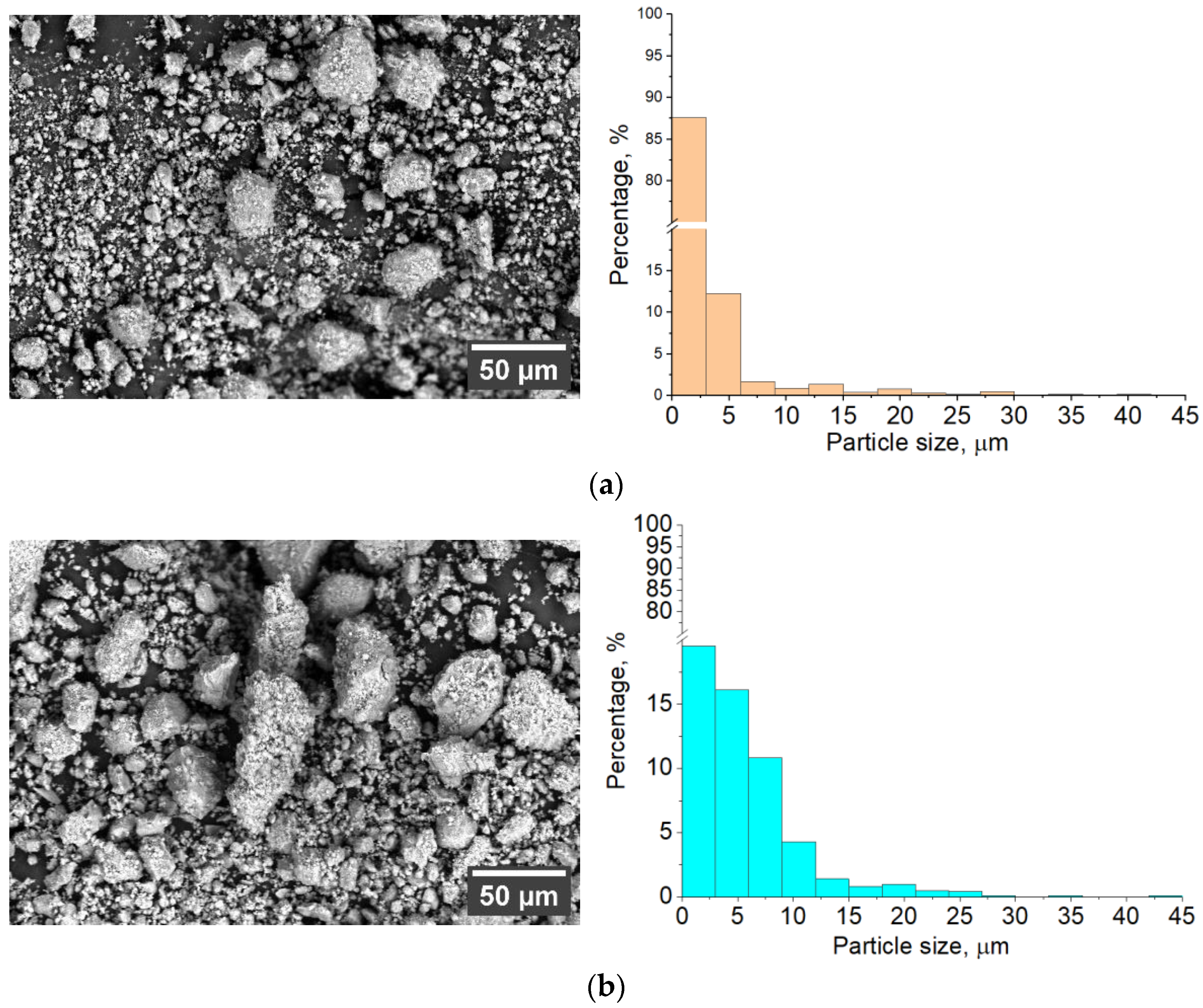
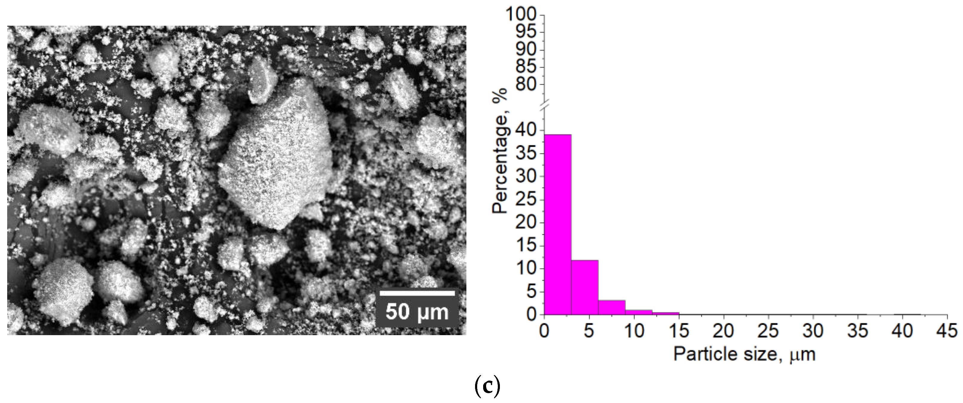
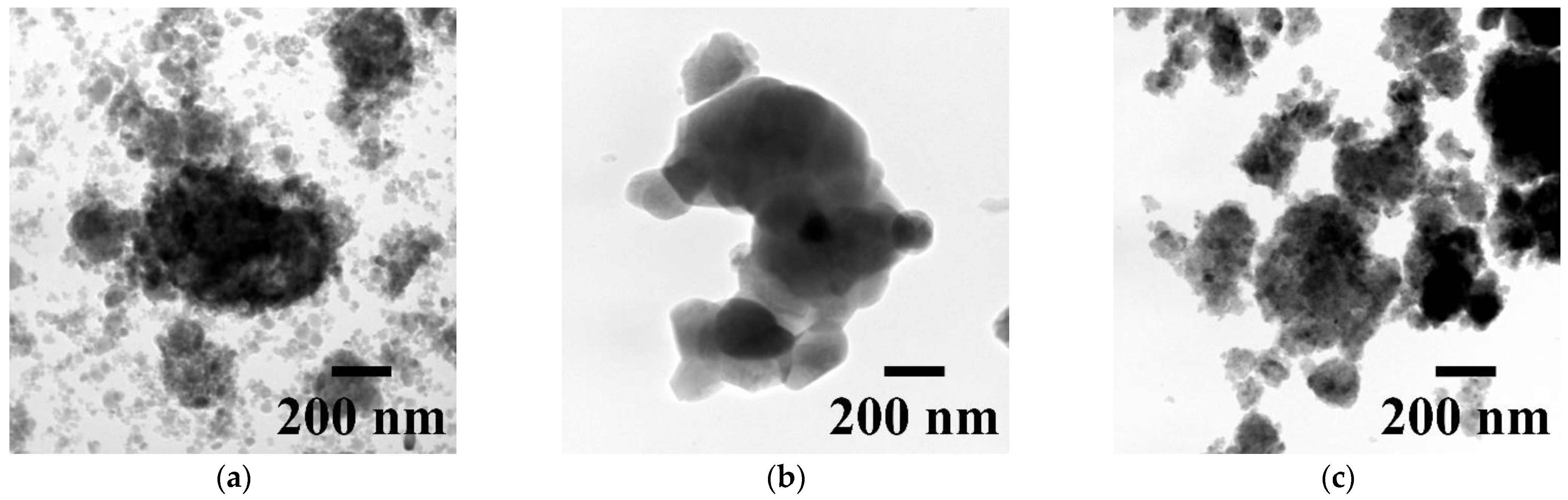
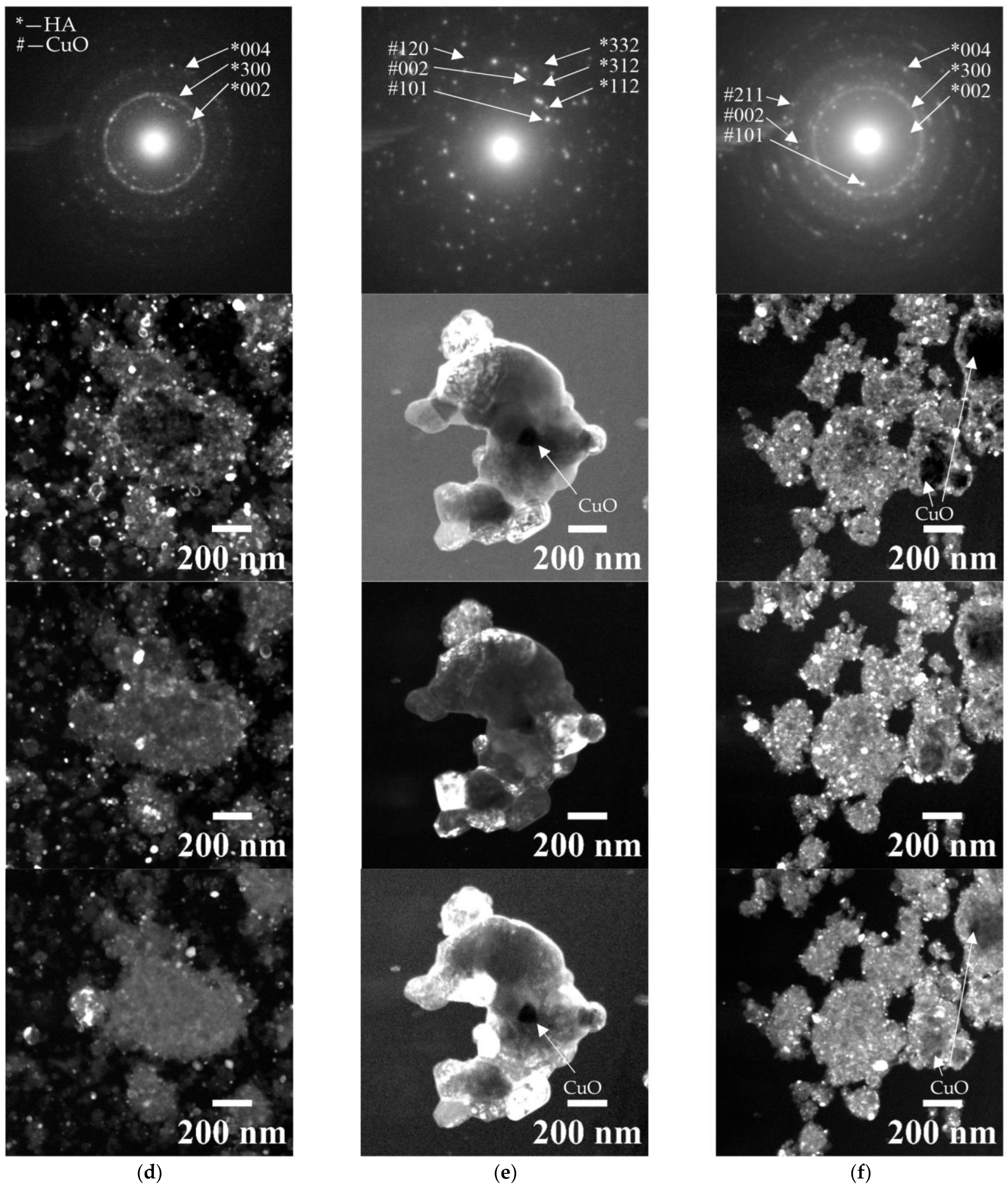
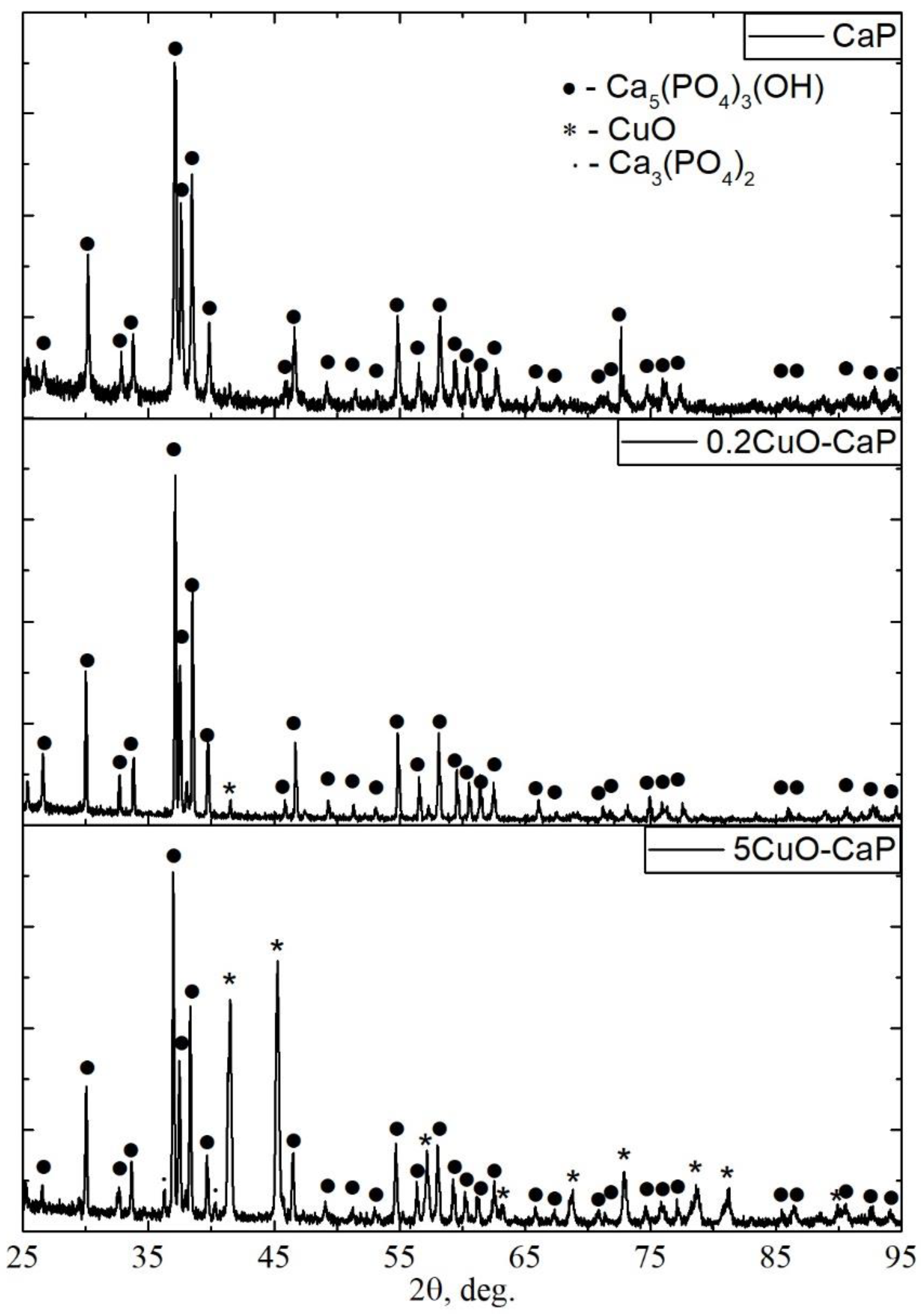
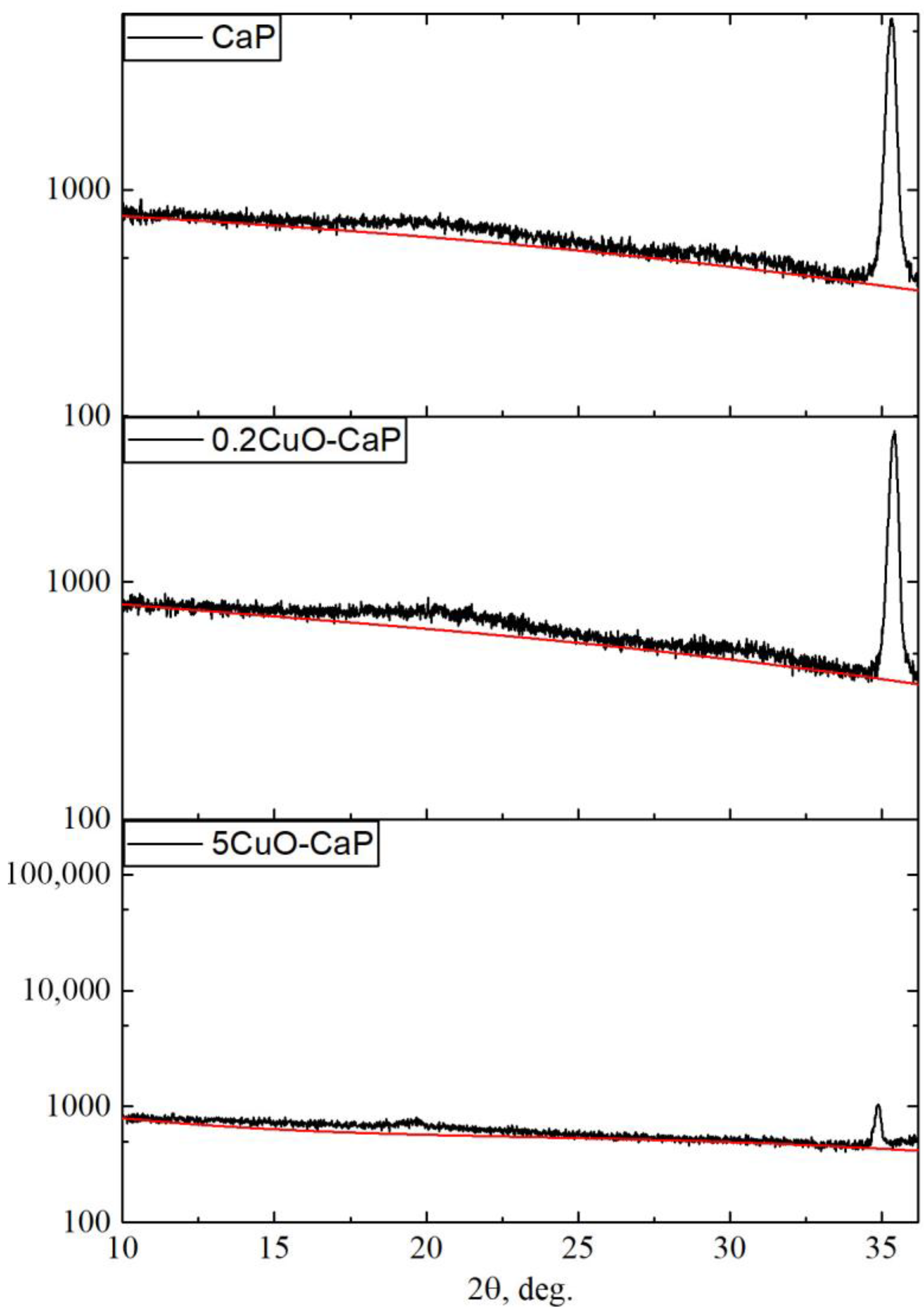
3.1. Characterization of Sintered Powders

X-ray diffraction (XRD) analysis was conducted on HA powders synthesized with varying concentrations of CuO (Figure 1), and results of calculated structural characteristics are summarized in Table 1. The nomenclature used for the samples throughout the study—CaP, 0.2CuO-CaP, and 5CuO-CaP—reflects the amount of CuO used in the synthesis process. XRD results revealed the presence of both HA and CuO phases in samples where a high concentration of CuO was used. Specifically, the crystal structure was determined to consist of 64% HA and 36% CuO. There could be a small quantity of CuO in the 0.2CuO-CaP sample (denoted by an asterisk); however, these reflections seem to overlap with those arising from the HA lattice.
Notably, the coherent scattering region of HA appeared to diminish with the addition of CuO. For the pure CaP, the coherent scattering region was found to be 94 ± 21 nm. However, for the 0.2CuO-CaP and 5CuO-CaP samples, the coherent scattering regions were 74 ± 13 nm and 18 ± 6 nm, respectively. This observation indicates that the CuO phase could be hindering the growth of HA crystals, leading to smaller crystal sizes with an increased concentration of CuO.
The alteration in the lattice parameter ‘a’ further corroborates this hypothesis. A gradual increase in the lattice parameter was observed as the CuO concentration increased. The ‘a’ parameter for CaP, 0.2CuO-CaP, and 5CuO-CaP was 9.4169 ± 0.0031 Å, 9.4211 ± 0.0042 Å, and 9.4344 ± 0.0086 Å, respectively. These results signify a potential distortion of the HA lattice structure due to the incorporation of Cu and interference of the CuO phase, as similarly reported in [44,45].
Considering these findings, it can be inferred that the addition of CuO not only interferes with the crystal growth of HA but may also result in the deformation of its crystal structure.
The introduction of Cu appears to significantly alter the microstructural and compositional properties of the powder, which is evident from SEM measurements (Figure 2). A noticeable trend was observed in the shape transition from more angular to rounder forms for 0.2CuO-CaP and 5CuO-CaP. There were also changes in the median particle size when CuO was incorporated. The median size for HA was 1.3 μm, while for 0.2CuO-CaP and 5CuO-CaP, the sizes were 4.1 μm and 2 μm, respectively. This shift may be attributed to the effect of Cu on the crystal growth of HA. With a greater Cu concentration, the HA crystals might experience inhibited growth, leading to smaller and more irregularly shaped particles. Turning to the EDX results, the Ca to P ratio, which is critical for calcium phosphates, showed a decrease as the Cu concentration increased. This might be due to the substitution of Ca ions by Cu ions in the HA lattice structure.
For the 5CuO-CaP sample, the Ca/P ratio was 1.61 ± 0.2 with 11.7 ± 2.6 at.% Cu, whereas for the 0.2CuO-CaP sample, the Ca/P ratio was 1.65 ± 0.2 with 0.48 ± 0.18 at.% Cu. The CaP sample showed a Ca/P ratio of 1.87 ± 0.45.
It is notable that the decrease in the Ca/P ratio did not exactly correspond to the increase in the Cu content. This discrepancy could be due to various factors, such as changes in the crystal structure, the formation of secondary phases, or the incomplete substitution of Ca ions by Cu ions.
In the TEM analysis, a marked difference in the morphology of CaP- and Cu-containing powders can be observed (Figure 3). The CaP powder comprises of nanometer-sized grain-like crystallites, characterized by well-defined, high-contrast boundaries. The crystallite size and strong contrast borders are indicative of a well-defined crystalline phase. The addition of CuO results in a deviation of crystallites, as is evident from the TEM results. This is consistent with the XRD results, which revealed a primarily HA phase for the CaP powder. The role of CuO during the mechanochemical process could be crucial to this behavior. Acting as a binder for the HA particles, the CuO could facilitate the formation of aggregates. The deviation in aggregate size governed by CuO content may also suggest an influence on the crystal growth process, with CuO possibly altering the growth kinetics or acting as a catalyst.
The detection of the CuO phase in the 5CuO-CaP powder via selected area electron diffraction (SAED) further substantiates this hypothesis. SAED patterns provide crystallographic information about the material, in this case revealing the presence of CuO in addition to the HA phase. This is further reinforced by the dark-field TEM image, which highlights the existence of Cu-containing species. For the 0.2CuO-CaP sample, the presence of the CuO phase was not prominent and could be found only in a few agglomerates, as depicted in Figure 3b, and which was confirmed by SAED. A crystallite that contains a significant concentration of Cu is revealed also by a notable change in contrast at the middle of an agglomerate. Otherwise, the sample is represented by an HA phase with distorted lattice parameters in relation to the ICDD database. However, it is worth noting that microscopy-based techniques, such as SEM and TEM, provide a very localized analysis. Therefore, to precisely monitor size deviation, alternative methods for particle size calculation should be employed. This, however, was not the primary focus of this research.
In conclusion of this subsection, it can be said that the combination of TEM, SAED, and dark-field imaging offers a detailed structural analysis of the synthesized powders, and, coupled with the SEM and XRD results, provides a comprehensive understanding of how CuO addition influences the crystal growth, aggregation, and phase composition of the HA powders.

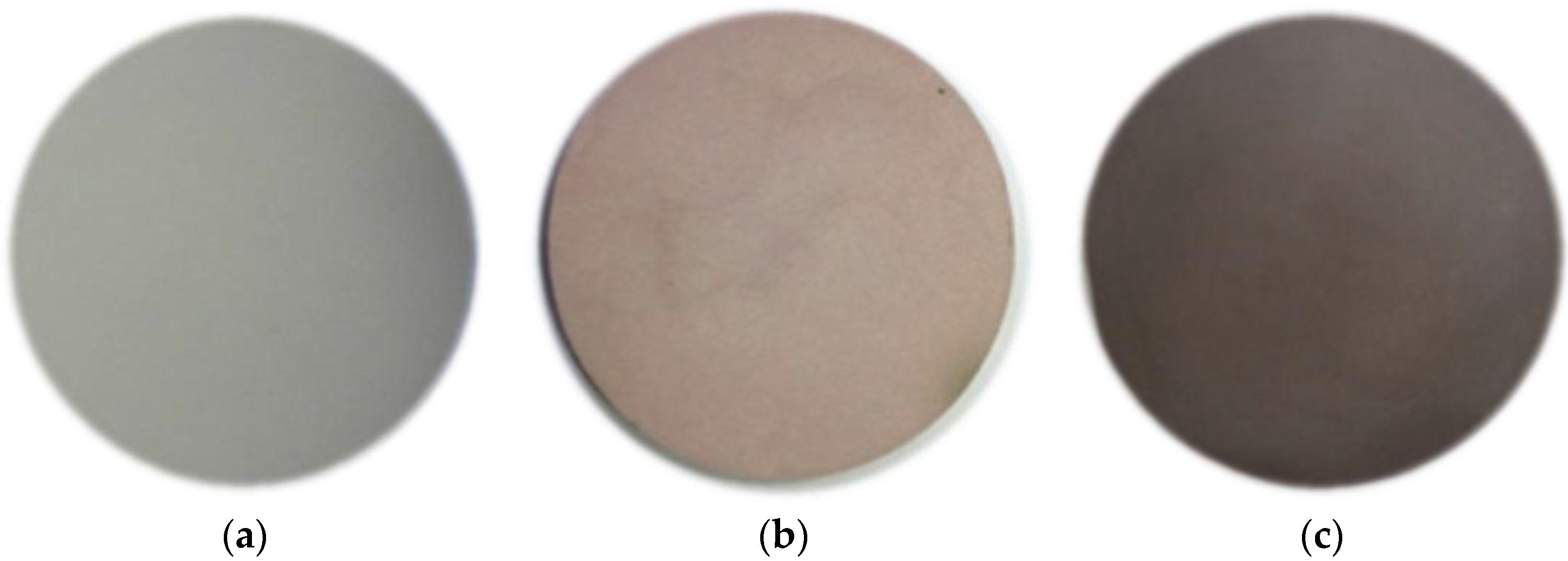
3.2. Sintered Targets for an RF Magnetron Sputtering

In Figure 4, we have presented optical images of sintered targets derived from CaP, 0.2CuO-CaP, and 5CuO-CaP powders. A striking observation from these images is the significant color shift from the pure white hue observed in the CaP target to the reddish and brownish shades seen in the 0.2CuO-CaP and 5CuO-CaP targets, respectively.
This alteration in color can be primarily attributed to the integration of Cu ions into the HA matrix. Cu, in its various oxidation states, brings about distinct colorations to the compounds it forms. In our case, the observable shift to reddish-brown is indicative of the presence of Cu(II) ions in the HA samples, similarly to what was previously reported for 3D sintering of Cu-containing HA [46], likely a consequence of Cu’s d-orbital electron transitions when exposed to specific light wavelengths.
This color transformation also suggests changes in the band structure of the material, due to the different energy levels available for electronic transitions. As the concentration of CuO increases, it becomes evident that Cu ions are integrated more prominently into the crystal structure and possibly a CuO phase was formed, resulting in the observed color shifts. In addition to providing a visual indication of successful Cu integration, these color changes also offer valuable insights into the local crystal environment.
In Figure 5, we have presented the SEM images of the sintered targets prepared from the CaP (a), 0.2CuO-CaP (b), and 5CuO-CaP powders. The corresponding EDX analysis reveals the following Ca/P ratios and Cu percentages: for the 5CuO-CaP sample, Ca/P is 1.61 ± 0.1 and Cu is 12.1 ± 0.18 at.%; for the 0.2CuO-CaP sample, Ca/P is 1.69 ± 0.1 and Cu is 0.51 ± 0.08 at.%; for the CaP sample, Ca/P is 1.78 ± 0.2.
The SEM images highlight discernible differences in the surface morphology of the sintered targets, contingent on the Cu content. The CaP target exhibits modest porosity, with the particle coalescence suggesting the impact of the 1100 °C annealing process. However, as we increment the Cu content slightly, it appears that Cu might act as a fluxing agent, yielding a considerably smoother surface for the 0.2CuO-CaP target. The visible grooves likely arose from the grinding step.
Interestingly, the second phase is not detectable in the 0.2CuO-CaP target. When the Cu content is boosted further to 5CuO-CaP, it becomes apparent that the surface of the target consists of two distinct phases. The bright spots are believed to be linked to the CuO phase; nevertheless, EDX mapping did not provide definitive confirmation. Considering the bulk target’s homogeneous Cu content, the EDX signal likely originates from not only the surface layer but also the lower layers. As a result, EDX mapping can only serve as an indicative tool in this context.
XRD analysis was conducted on sintered targets with varying concentrations of CuO (Figure 6), and the results of the calculated structural characteristics are summarized in Table 2. Based on the X-ray diffraction analysis of sintered targets, it is evident that the sintering process significantly impacted the crystal structure and phase composition of the samples, particularly those with CuO.
For the CaP and 0.2CuO-CaP samples, the HA phase is dominant and is indicated by the sharp and high-intensity peaks in their diffractograms. The lattice parameters for these samples are close to the standard values for HA according to the ICDD database, signifying that the HA structure is maintained during sintering. It is interesting to note that the ‘a’ lattice parameter for the 0.2CuO-CaP sample slightly decreased compared to the powdered form, which might suggest a slight rearrangement or more ordered packing of atoms within the HA structure during sintering. The crystallite size, represented by the coherent scattering region (CSR), was slightly decreased for 0.2CuO-CaP, which could be due to the effect of sintering conditions on crystal growth. On the other hand, for the 5CuO-CaP sample, the presence of CuO had a more pronounced effect. Here, the phase composition consists of HA (54%), CuO (42%) and TCP (3%), indicating that a significant portion of the CuO is present after sintering. This CuO phase might have acted as a binding agent during sintering, which promoted densification and possibly inhibited the growth of HA crystals. Moreover, due to the high temperature influence, a small portion of TCP appeared. The ‘a’ lattice parameter in this sample slightly increased compared to the powdered form, suggesting some lattice distortion or expansion, likely due to the incorporation of Cu ions into the HA structure. The CSR also decreased compared to the powdered form, indicating that the crystal size became smaller, potentially due to the hindrance of crystal growth by the CuO phase.
These results indicate that the sintering process, in conjunction with the CuO concentration, plays a critical role in the phase composition, crystal structure, and crystallinity.
In conclusion to this subsection, it could be said that the inclusion of CuO significantly influenced the structural properties of HA in sintered targets. Lower CuO concentrations maintained the HA crystal structure, while high CuO concentrations revealed a HA-CuO mixed-phase composition. Distinct variations in structural parameters suggested potential lattice distortion and crystal size variation due to the CuO concentration and sintering effects. The CuO content also affected the target’s visual appearance, leading to color change, and resulted in a smoother surface. These observations highlight the profound effect of CuO and sintering on the HA structure, paving the way for the improved design of HA-based materials. Further investigations will extend these findings, exploring the suitability of the sintered targets for RF magnetron sputtering.

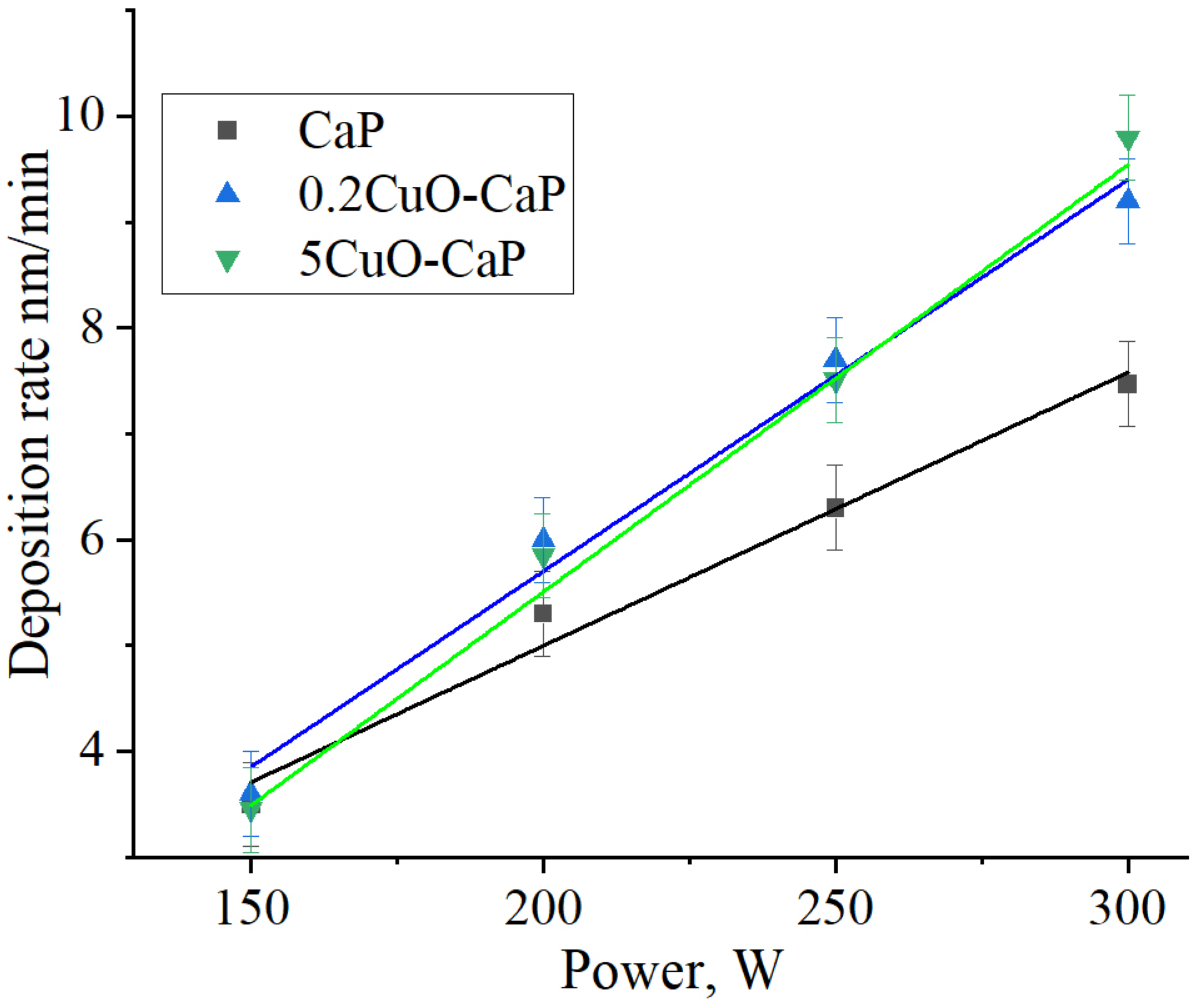
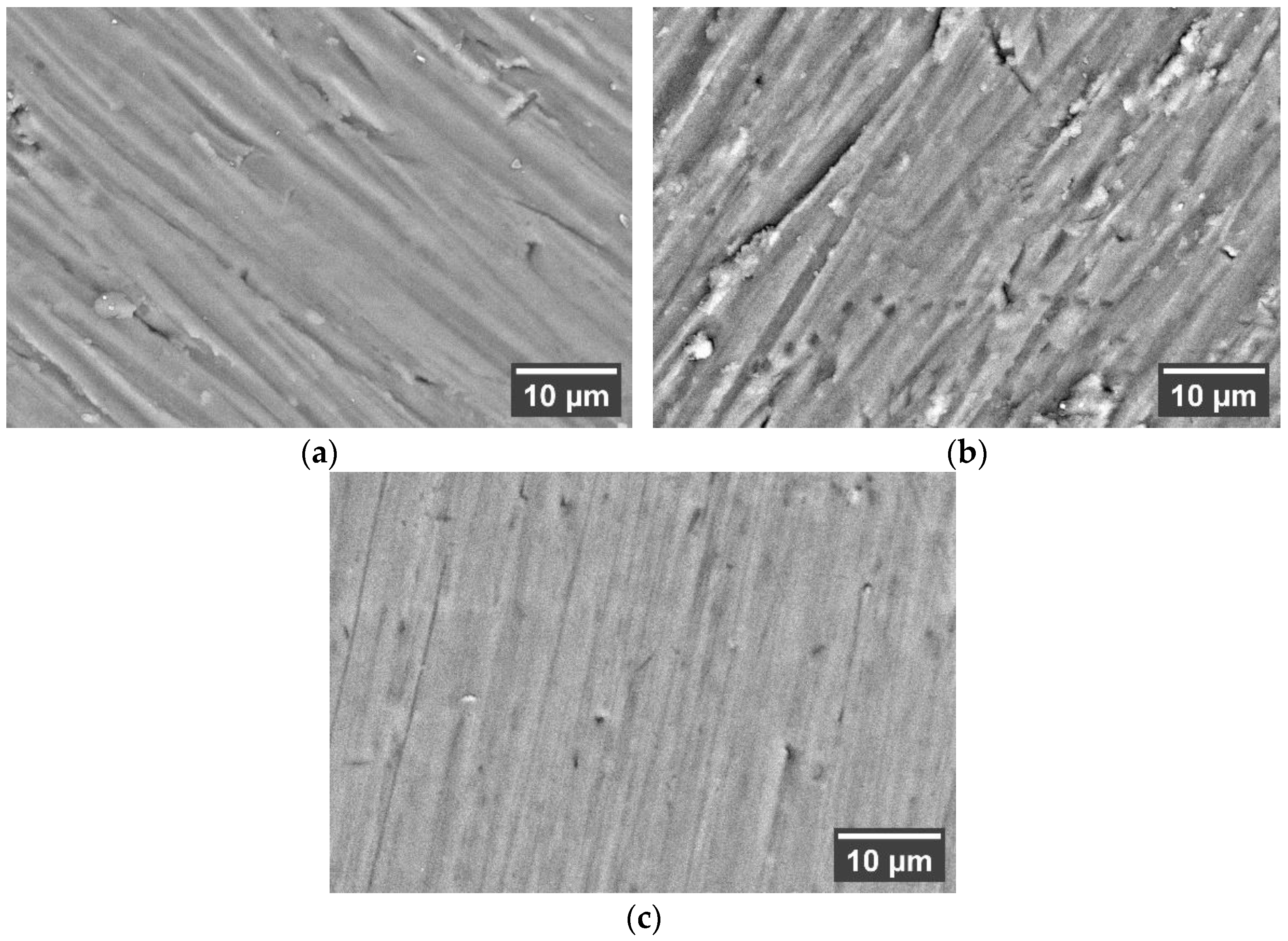
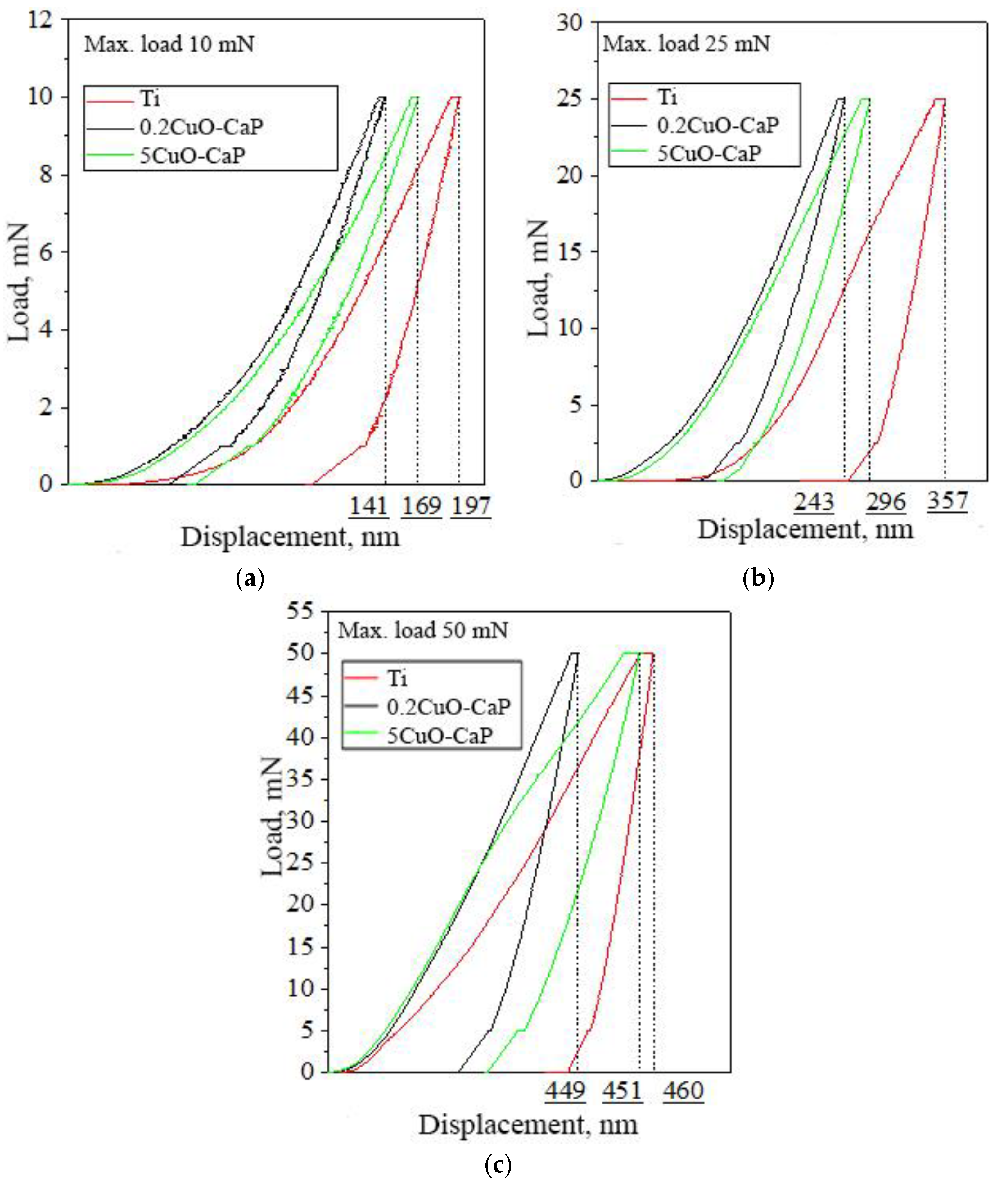
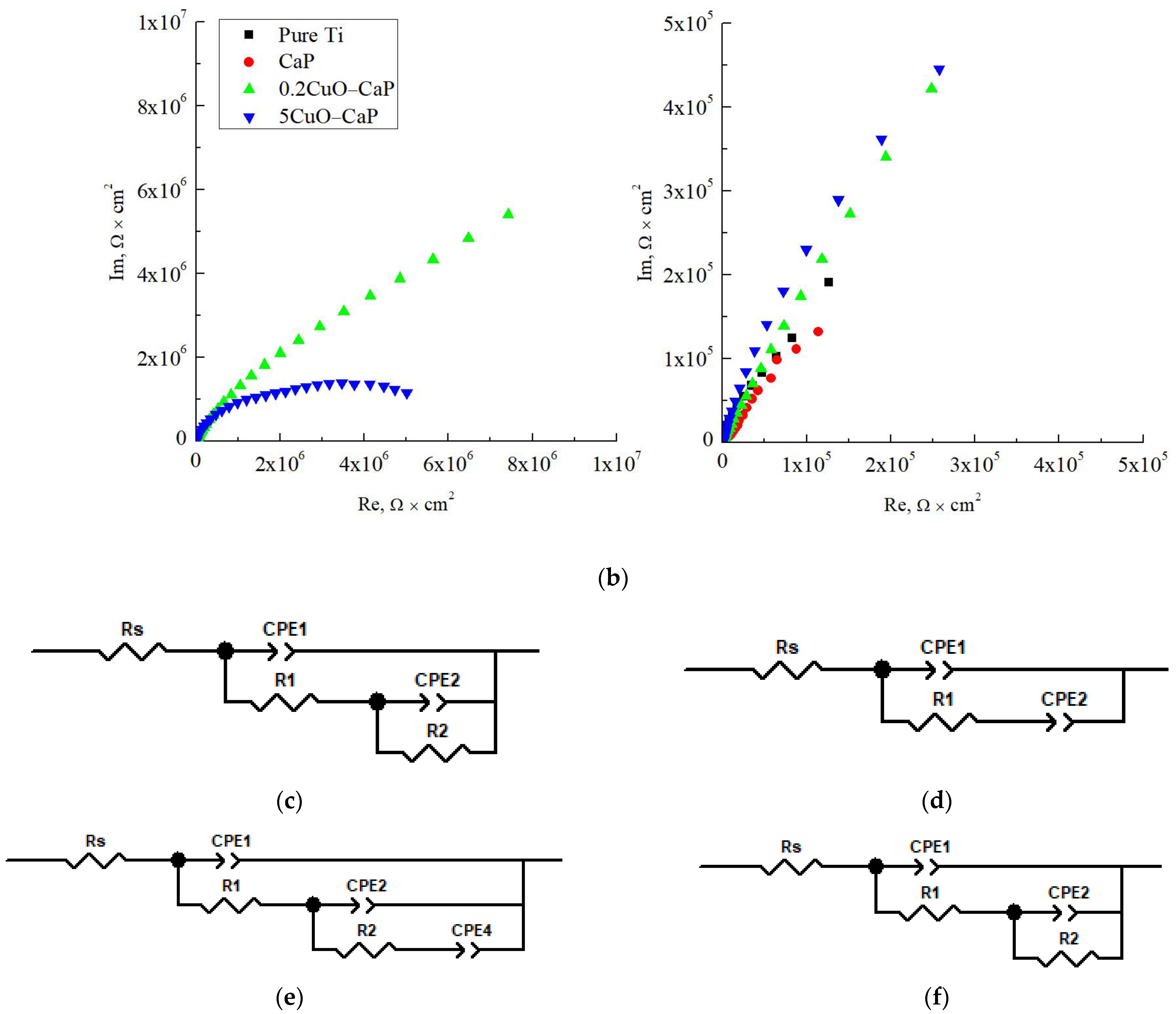
3.3. Analysis of Deposited Coatings

The deposition rate is an essential characteristic that should be researched as it allows one to precisely control the coating thickness. In Figure 7, the deposition rate from all targets is reported. As observed from the SEM analysis of the sintered 5CuO-CaP target, there is clear phase segregation, resulting in two distinct phases. The presence of two distinct phases suggests a differential sputtering yield for the HA (CaP) and CuO phases. Given the inherent material properties, it is reasonable to propose that the CuO phase may have a higher sputtering yield compared to the CaP phase.
The sputtering yield is influenced by several factors, including the mass and binding energy of the target material. CuO, being a metal oxide, likely has a lower binding energy compared to the complex HA structure, making it easier to sputter. Thus, areas of the target with a higher concentration of the CuO phase, due to phase segregation, would exhibit higher sputtering yields, leading to higher deposition rates.
Comparatively, the 0.2CuO-CaP target, with a lower Cu content, shows a more uniform and smooth surface under SEM. This implies a more homogeneous distribution of the CuO phase within the CaP matrix. This homogeneity would moderate the differences in sputtering yield across the target, resulting in a lower deposition rate than the 5CuO-CaP target, but higher than the pure CaP target. Lastly, the pure CaP target, without the presence of CuO, would likely exhibit the lowest sputtering yield among the three due to its higher binding energy and complex crystalline structure. Therefore, this results in the lowest deposition rate among the three targets.
Based on the SEM analysis (Figure 8), it was observed that all deposited coatings mimicked the surface structure of the ground Ti substrate, resulting in visibly marked grooves and ridges. Notably, the smoothest surface was evidenced in the case of the 5CuO-CaP sample, an outcome that might be attributable to an incremental increase in the deposition rate. The measured Ca/P ratios for each sample revealed distinct variations in stoichiometry. For the CaP sample, the Ca/P ratio was found to be 1.91 ± 0.2, deviating from the stoichiometric ratio of 1.67 for pure HA. An even higher deviation was observed for the 0.2CuO-CaP sample, with a Ca/P ratio of 2.22 ± 0.3, while maintaining a minimal Cu content of 0.4 at.%.
Contrastingly, the 5CuO-CaP sample exhibited a Ca/P ratio of 1.62 ± 0.1, which was closest to the stoichiometric ratio for HA, while simultaneously maintaining a significant Cu content of 12.6 ± 0.5 at.%. This observation indicates that the increase in Cu content led to the Ca/P ratio being closest to HA, while also introducing substantial amounts of Cu. It is a well-known fact that the Ca/P ratio is altered by the sputtering yield and re-sputtering of growing film. Interestingly, a high content of Cu could improve the stoichiometry of deposited using RF magnetron sputtering coatings.
A detailed analysis of the deposited coatings was conducted using X-ray diffraction (XRD) in order to assess the potential presence of CuO in the coatings and to study the structure of the deposited layers (Figure 9). From the XRD data, it is clear that only the peak corresponding to the Ti substrate could be distinctly identified in the area of interest. Concurrently, a halo arising from the amorphous calcium phosphate was observed for all the deposited coatings.
Interestingly, the short-range order, evidenced by the halo intensity, appears to be affected by the presence of Cu, suggesting that the local structure of the amorphous calcium phosphate may be modulated by CuO incorporation. Despite the high-sensitivity and comprehensive data provided by XRD, their efficacy for the analysis of thin solid films and low dopant concentrations can be limited.
For a more nuanced understanding of the structure and short-range order of the deposited layers, a cross-section TEM analysis is recommended. This technique will offer a more in-depth analysis and potentially reveal structural intricacies that could be pivotal in understanding the effect of CuO incorporation on the physical and chemical properties of the coatings.
Load–unload curves (Figure 10) for the 0.2CuO-CaP and 5CuO-CaP were analyzed under loads of 10, 25, and 50 mN in relation to the unmodified Ti substrate. A reduction in the surface indentation depth was observed, indicating an increased hardness of the coating relative to the Ti substrate. By examining the area under the load and unload curves, it is clear that the recovery behavior of the coatings exhibits an elastic–plastic nature (smaller area under the curve), while the recovery of Ti shows predominantly plastic behavior (larger area under the curve).
Further, the mechanical properties (hardness, modulus of elasticity, and plasticity (δ)) of the sample surfaces were assessed. The indentation depth (h) in the coatings was less than in Ti, a distinction attributable to the variance in the mechanical properties (hardness and modulus of elasticity) of the coating and the Ti substrate. It is a well-known fact that ceramics exhibit a higher level of hardness; however, even amorphous thin CaP films also reflect the high values of hardness. The plasticity of the coating was almost half that of the Ti samples (under loads of 10 and 25 mN), suggesting a predominance of elastic properties in the coatings, while the polished titanium specimens exhibited a more plastic-deformation behavior.
As the indentation depth increased, the influence of the Ti substrate became more significant, causing the hardness and modulus of elasticity of the coatings (0.2CuO-CaP: H = 16 GPa, E = 272 GPa; 5CuO-CaP: H = 17 GPa, E = 211 GPa) to decrease to values close to those of titanium (H = 13 GPa, E = 360 GPa) (Figure 11). The mechanical properties of the coatings were analyzed using data obtained at a 10 mN load because the indentation depth was minimal and the substrate influence was minimized, as evidenced by the measured values of the hardness and modulus of elasticity (0.2CuO-CaP: H = 37 GPa, E = 503 GPa; 5CuO-CaP: H = 30 GPa, E = 304 GPa).
It is noteworthy that the coating with a lower Cu content exhibited a higher hardness and modulus of elasticity than the coating with a higher Cu content. The observed mechanical properties of the coatings, particularly the hardness and modulus of elasticity, are largely attributed to their amorphous nature and the specific influence of the incorporated Cu. These mechanical enhancements, coupled with the already-known biocompatible nature of these coatings, highlight their potential utility in various orthopedic and dental applications.
The higher hardness and modulus of elasticity in the coating with the lower Cu content could be related to the reduced phase segregation. This may be due to the fact that with increasing Cu content, there is an increase in the proportion of the softer CuO phase, which would affect the overall hardness and modulus of elasticity of the coating. It is also possible that the introduction of a larger amount of CuO could lead to structural defects, further reducing these mechanical properties. However, it has not been reliably proven by XRD analysis. On the other hand, the lower Cu content may have facilitated a more homogenous distribution of the elements, leading to more-uniform mechanical properties.
Additionally, as the indentation depth increased, the influence of the Ti substrate became more prominent, causing the hardness and modulus of elasticity of the coatings to decrease towards the values for Ti. This is indicative of the effect of the substrate material properties at a larger indentation depth.
Finally, the electrochemical parameters of the deposited coatings were studied and Tafel slopes are presented in Figure 12. The corrosion characteristics of the material samples were presented in Table 3. The Open Circuit Potential (Eocp) for pure Ti was found to be −0.03 ± 0.03 V while the corrosion potential (Ecorr) was at −0.32 ± 0.03 V, with a corrosion current density (Jcorr) of 60.2 ± 5.2 nA/cm2. The corrosion rate was significantly higher in the case of the unmodified Ti sample compared to the coated samples, indicating their improved corrosion resistance due to the coating. The CaP-coated sample demonstrated a considerably lower corrosion current density (3.9 ± 0.5 nA/cm2), which corresponds to a higher polarization resistance (Rp) of 16.0 MOhm/cm2, indicating a lower rate of corrosion compared to the uncoated Ti sample.
Adding a small amount of Cu in the CaP coating (0.2CuO-CaP) resulted in an increase in the corrosion current density (16.3 ± 1.6 nA/cm2) compared to the CaP coated sample, but still much lower than the uncoated Ti sample. The corresponding polarization resistance was 4.4 MOhm/cm2. When a higher amount of Cu was added (5CuO-CaP), the corrosion current density decreased to 6.4 ± 1.1 nA/cm2, indicating improved corrosion resistance compared to the 0.2CuO-CaP sample. The polarization resistance increased to 9.4 MOhm/cm2.
From these results, it is evident that the addition of Cu to the CaP coating affects the corrosion characteristics of the coated Ti samples. This is especially true in the case of the 5CuO-CaP sample, which demonstrated superior corrosion resistance characteristics compared to the other samples. The data of the corrosion characteristics suggest an intriguing relationship between the doping concentration and the conductivity of the CaP coatings. The addition of a small amount of Cu (0.2CuO-CaP) appears to significantly enhance the conductivity of the CaP. This increase could be attributed to a shift from ion conductivity to electron conductivity, a transition that has been observed in other metal-doped ceramic systems as Cu-doping results in an increase in the charge carrier concentration [47]. However, increasing the Cu concentration further (5CuO-CaP) seems to reduce the conductivity. This trend may be attributed to the presence of CuO clusters in the coating, originating from the CuO in the target material used for deposition. CuO is known to behave as a dielectric, which might hinder its electron movement, thus decreasing its overall conductivity. An increase in insulating properties upon the increase in CuO content has been reported elsewhere [48].
Furthermore, impedance spectroscopy was performed for the deposited coatings, and Bode and Nyquist plots are presented in Figure 13a,b. Using these results, an equivalent circuit was modeled (Figure 13c–f). An equivalent circuit for a pure Ti sample is shown below (Figure 13c), consistent with the findings of other researchers [49]. This equivalent circuit, generally speaking, comprises three components: the active resistance of pure Ti (Rs), the TiO2 oxide layer (CPE1, R1), and the interface between the electrolyte and oxide layer (CPE2, R2). The constant phase element (CPE) involves the charge transfer process related to the dispersion of a capacitance around a mean value, and can be modeled by two parameters, CPE-T and CPE-P. CPE was used here since it is more suitable to describe the non-ideal behavior of the coating. This circuit was characteristic of all metallic samples with a dielectric coating; in this case, the coating was the TiO2 oxide layer. The values for simulated elements are presented in Table 4.
Since impedance measurements were performed at low frequencies (0.01–1 Hz) in this study, it was necessary to confirm whether these system data are stationary. For this, a Kramers–Kronig transformation (KK) was performed for each of the impedance spectra with the subsequent calculation of χ2 as a parameter to assess the accuracy of the approximation. These values are provided in Table 3. All spectra demonstrated high convergence (χ2 < 0.1) after the transformation, which allowed us to assert the correctness of the selection of equivalent circuits at low-frequency intervals. In the case of the Pure Ti sample, the χ2 value was slightly inflated compared to other samples due to the active resistance Rs, a more precise value of which could not be calculated.
It should be noted that as the proportion of copper oxide in the coating structure increases, the capacitance of the CPE1-P element decreases. This may suggest a higher conductivity of the TiO2 surface layer in the case of the 5CuO-CaP sample. In the case of active resistances (R1, R2), their value increases, which indicates an increase in the proportion of active resistance when alloying the coating with copper.
The deposition of a coating (Figure 13d) modifies the nature of the third component, increasing the influence of the reactive resistance; therefore, R2 is excluded from the equivalent circuit. This behavior is associated with the dielectric conductivity of the transition layer CaP-electrolyte, which at low frequencies possesses a quasi-infinite active resistance. The addition of a small amount of Cu to the CaP coating (Figure 13e) adds another component to the equivalent circuit (CPE4) and leads to a limit in the active resistance of the third component. The fourth component characterizes the interface between the Cu-electrolyte, since small amounts of Cu do not form a uniform matrix, and the element is evenly distributed throughout the CaP layer as separate species in the amorphous matrix of CaP.
Adding more Cu content to the CaP coating (Figure 13f) leads to the exclusion of the fourth component due to the fact that Cu particles begin to form a uniform matrix within the CaP layer. Hence, the surface layer now comprises a unified structure in the form of a CuO-CaP composite, characterized only by the third component, similar to the case of pure Ti with a TiO2 oxide layer. This suggests that the addition of higher concentrations of Cu change the electrochemical properties of the CaP layer.
These observations suggest the potential of tuning the electrical properties of CaP coatings by careful control over the dopant concentration. Given the growing interest in the electro-physical properties of biomedical coatings due to their potential use in implantable detectors, transducers, and actuators, this finding may have significant implications for future research. In particular, the enhancement of electrical properties of CaP coatings may pave the way for more advanced and functional biomedical implant coatings.

4. Conclusions

The transition of CuO-doped CaP materials from powders to ceramics to coatings demonstrated a significant evolution in their structural and elemental parameters. With lattice parameters for ceramics (a = 9.420 Å and c = 6.884 Å) notably higher than for the raw powders (a = 9.413 Å and c = 6.875 Å), we confirmed successful CuO incorporation into the HA lattice. The Ca/P ratio underwent an interesting transition from powders to ceramics and coatings. For example, the Ca/P ratio decreased from 2.22 ± 0.3 in 0.2CuO-CaP powder to 1.62 ± 0.1 in 5CuO-CaP coating. Simultaneously, the Cu content ascended from less than 0.4 at.% in the initial powder to an impressive 12.6 ± 0.5 at.% in the final coating, denoting the material’s adaptability. Mechanical tests showed the hardness and Young’s modulus of the coatings to be much higher than those of the Ti substrate, with the 0.2CuO-CaP coating exhibiting the highest hardness (H = 37 GPa) and modulus (E = 503 Gpa). In terms of electrochemical performance, the 0.2CuO-CaP coating exhibited an appreciable decrease in corrosion current density (16.3 ± 1.6 nA/cm2) compared to pure Ti (60.2 ± 5.2 nA/cm2), along with an increase in polarization resistance (4.4 Mohm/cm2). The TEM study highlighted the need for in-depth layer analysis for thin solid films and low dopant concentrations, revealing a short-range order modification induced by the presence of Cu. It is important to note that comprehensive, long-term testing under physiological conditions, including evaluations of structural, mechanical, and electrochemical behavior, is essential to substantiate our findings. Our forthcoming research will be dedicated to assessing the cytotoxicity, immunological activity, and antibacterial effect of such coatings with an increased Cu content. With enhanced mechanical strength and electrochemical resilience, these coatings possess considerable potential for biomedical applications, such as implantable sensors and actuators. In conclusion, our study demonstrates the remarkable adaptability and tunability of CuO-doped CaP materials across various phases, underscoring their potential in materials science and biomedical applications. The structural, mechanical, and electrochemical enhancements realized through controlled Cu doping highlight the promise of this material for future research and practical applications.

Author Contributions

Conceptualization, K.P.; methodology, K.P. and V.L.; software, K.P. and N.L.; validation, K.P., M.K. and A.K.; formal analysis, K.P., V.L. and I.G.; investigation, K.P., N.L., A.K., M.K. and I.G.; resources, Y.S.; data curation, K.P. and Y.S.; writing—original draft preparation, K.P.; writing—review and editing, K.P.; visualization, K.P., M.K. and A.K.; supervision, K.P.; project administration, Y.S.; funding acquisition, Y.S. All authors have read and agreed to the published version of the manuscript.

Funding

The work was performed according to the Government research assignment for ISPMS SB RAS, project FWRW-2021-0007.

Institutional Review Board Statement

Not applicable.

Informed Consent Statement

Not applicable.

Data Availability Statement

Data is available after reasonable request.

Acknowledgments

The authors express their appreciation for the valuable contributions of A.I. Tolmachev from Institute of Strength Physics and Materials Science SB RAS (Tomsk, Russia) for their assistance in the preparation of the experimental materials. The investigations were carried out using the equipment of Share Use Centre “Nanotech” of the ISPMS SB RAS and Tomsk Materials Research Multiple Access Center of TSU, as well as the instrumental base of TPU. The authors also thank M.V. Chaikina and N.V. Bulina’s team from the Institute of Mechanochemistry, Novosibirsk, Russia for synthesizing the HA powder.

Conflicts of Interest

The authors declare no conflict of interest.

References

  1. Germaini, M.-M.; Belhabib, S.; Guessasma, S.; Deterre, R.; Corre, P.; Weiss, P. Additive Manufacturing of Biomaterials for Bone Tissue Engineering—A Critical Review of the State of the Art and New Concepts. Prog. Mater. Sci. 2022, 130, 100963. [Google Scholar] [CrossRef]
  2. Basu, B.; Gowtham, N.H.; Xiao, Y.; Kalidindi, S.R.; Leong, K.W. Biomaterialomics: Data Science-Driven Pathways to Develop Fourth-Generation Biomaterials. Acta Biomater. 2022, 143, 1–25. [Google Scholar] [CrossRef]
  3. Rial, R.; Liu, Z.; Messina, P.; Ruso, J.M. Role of Nanostructured Materials in Hard Tissue Engineering. Adv. Colloid Interface Sci. 2022, 304, 102682. [Google Scholar] [CrossRef] [PubMed]
  4. Wickramasinghe, M.L.; Dias, G.J.; Premadasa, K.M.G.P. A Novel Classification of Bone Graft Materials. J. Biomed. Mater. Res. 2022, 110, 1724–1749. [Google Scholar] [CrossRef] [PubMed]
  5. Jain, S.; Parashar, V. Analytical Review on the Biocompatibility of Surface-Treated Ti-Alloys for Joint Replacement Applications. Expert Rev. Med. Devices 2022, 19, 699–719. [Google Scholar] [CrossRef] [PubMed]
  6. Khimich, M.A.; Prosolov, K.A.; Mishurova, T.; Evsevleev, S.; Monforte, X.; Teuschl, A.H.; Slezak, P.; Ibragimov, E.A.; Saprykin, A.A.; Kovalevskaya, Z.G.; et al. Advances in Laser Additive Manufacturing of Ti-Nb Alloys: From Nanostructured Powders to Bulk Objects. Nanomaterials 2021, 11, 1159. [Google Scholar] [CrossRef] [PubMed]
  7. Vishwakarma, V.; Kaliaraj, G.S.; Amirtharaj Mosas, K.K. Multifunctional Coatings on Implant Materials—A Systematic Review of the Current Scenario. Coatings 2022, 13, 69. [Google Scholar] [CrossRef]
  8. Kroczek, K.; Turek, P.; Mazur, D.; Szczygielski, J.; Filip, D.; Brodowski, R.; Balawender, K.; Przeszłowski, Ł.; Lewandowski, B.; Orkisz, S.; et al. Characterisation of Selected Materials in Medical Applications. Polymers 2022, 14, 1526. [Google Scholar] [CrossRef]
  9. Wang, R.; Ni, S.; Ma, L.; Li, M. Porous Construction and Surface Modification of Titanium-Based Materials for Osteogenesis: A Review. Front. Bioeng. Biotechnol. 2022, 10, 973297. [Google Scholar] [CrossRef]
  10. El-Saies, M.M.; Hassan, I.; El-Shazly, A.H.; El-Wakad, M.T. Titanium Foam for Dental Implant Applications: A Review. SVU-Int. J. Eng. Sci. Appl. 2023, 4, 107–112. [Google Scholar] [CrossRef]
  11. Ho, D.; Quake, S.R.; McCabe, E.R.B.; Chng, W.J.; Chow, E.K.; Ding, X.; Gelb, B.D.; Ginsburg, G.S.; Hassenstab, J.; Ho, C.-M.; et al. Enabling Technologies for Personalized and Precision Medicine. Trends Biotechnol. 2020, 38, 497–518. [Google Scholar] [CrossRef] [PubMed]
  12. Shen, J.; Gao, P.; Han, S.; Kao, R.Y.T.; Wu, S.; Liu, X.; Qian, S.; Chu, P.K.; Cheung, K.M.C.; Yeung, K.W.K. A Tailored Positively-Charged Hydrophobic Surface Reduces the Risk of Implant Associated Infections. Acta Biomater. 2020, 114, 421–430. [Google Scholar] [CrossRef] [PubMed]
  13. Lisoń, J.; Taratuta, A.; Paszenda, Z.; Szindler, M.; Basiaga, M. Perspectives in Prevention of Biofilm for Medical Applications. Coatings 2022, 12, 197. [Google Scholar] [CrossRef]
  14. Nouri, A.; Rohani Shirvan, A.; Li, Y.; Wen, C. Surface Modification of Additively Manufactured Metallic Biomaterials with Active Antipathogenic Properties. Smart Mater. Manuf. 2023, 1, 100001. [Google Scholar] [CrossRef]
  15. Perrault, D.P.; Sharma, A.; Kim, J.F.; Gurtner, G.C.; Wan, D.C. Surgical Applications of Materials Engineered with Antimicrobial Properties. Bioengineering 2022, 9, 138. [Google Scholar] [CrossRef]
  16. Prosolov, K.A.; Mitrichenko, D.V.; Prosolov, A.B.; Nikolaeva, O.O.; Lastovka, V.V.; Belyavskaya, O.A.; Chebodaeva, V.A.; Glukhov, I.A.; Litvinova, L.S.; Shupletsova, V.V.; et al. Zn-Doped CaP-Based Coatings on Ti–6Al–4V and Ti–6Al–7Nb Alloys Prepared by Magnetron Sputtering: Controllable Biodegradation, Bacteriostatic, and Osteogenic Activities. Coatings 2021, 11, 809. [Google Scholar] [CrossRef]
  17. Prosolov, K.A.; Lastovka, V.V.; Belyavskaya, O.A.; Lychagin, D.V.; Schmidt, J.; Sharkeev, Y.P. Tailoring the Surface Morphology and the Crystallinity State of Cu- and Zn-Substituted Hydroxyapatites on Ti and Mg-Based Alloys. Materials 2020, 13, 4449. [Google Scholar] [CrossRef]
  18. Prosolov, K.A.; Lastovka, V.V.; Khimich, M.A.; Chebodaeva, V.V.; Khlusov, I.A.; Sharkeev, Y.P. RF Magnetron Sputtering of Substituted Hydroxyapatite for Deposition of Biocoatings. Materials 2022, 15, 6828. [Google Scholar] [CrossRef]
  19. Sedelnikova, M.B.; Komarova, E.G.; Sharkeev, Y.P.; Ugodchikova, A.V.; Mushtovatova, L.S.; Karpova, M.R.; Sheikin, V.V.; Litvinova, L.S.; Khlusov, I.A. Zn-, Cu- or Ag-Incorporated Micro-Arc Coatings on Titanium Alloys: Properties and Behavior in Synthetic Biological Media. Surf. Coat. Technol. 2019, 369, 52–68. [Google Scholar] [CrossRef]
  20. Ielo, I.; Calabrese, G.; De Luca, G.; Conoci, S. Recent Advances in Hydroxyapatite-Based Biocomposites for Bone Tissue Regeneration in Orthopedics. Int. J. Mol. Sci. 2022, 23, 9721. [Google Scholar] [CrossRef]
  21. Bulina, N.V.; Vinokurova, O.B.; Eremina, N.V.; Prosanov, I.Y.; Khusnutdinov, V.R.; Chaikina, M.V. Features of Solid-Phase Mechanochemical Synthesis of Hydroxyapatite Doped by Copper and Zinc Ions. J. Solid State Chem. 2021, 296, 121973. [Google Scholar] [CrossRef]
  22. Chaikina, M.V.; Bulina, N.V.; Prosanov, I.Y.; Vinokurova, O.B.; Ishchenko, A.V. Structure Formation of Zinc-Substituted Hydroxyapatite during Mechanochemical Synthesis. Inorg. Mater. 2020, 56, 402–408. [Google Scholar] [CrossRef]
  23. Khvostov, M.V.; Borisova, M.S.; Bulina, N.V.; Makarova, S.V.; Dumchenko, N.B.; Tolstikova, T.G.; Lyakhov, N.Z. The Influence of Zinc and Silicate Ions on Biological Properties of Hydroxyapatite Synthesized by a Mechanochemical Method. Ceram. Int. 2021, 47, 9495–9503. [Google Scholar] [CrossRef]
  24. Prosolov, K.A.; Luginin, N.A.; Litvinova, L.S.; Fedorov, M.A.; Anisenya, I.I.; Mushtovatova, L.S.; Snetkov, A.A.; Bukharov, A.V.; Khlusov, I.A.; Sharkeev, Y.P. Antibacterial and Biocompatible Zn and Cu Containing CaP Magnetron Coatings for MgCa Alloy Functionalization. J. Mater. Res. Technol. 2023, 25, 2177–2203. [Google Scholar] [CrossRef]
  25. Akhtar, M.; Uzair, S.A.; Rizwan, M.; Ur Rehman, M.A. The Improvement in Surface Properties of Metallic Implant via Magnetron Sputtering: Recent Progress and Remaining Challenges. Front. Mater. 2022, 8, 747169. [Google Scholar] [CrossRef]
  26. Montazerian, M.; Hosseinzadeh, F.; Migneco, C.; Fook, M.V.L.; Baino, F. Bioceramic Coatings on Metallic Implants: An Overview. Ceram. Int. 2022, 48, 8987–9005. [Google Scholar] [CrossRef]
  27. Ueda, K.; Narushima, T. Amorphous Calcium Phosphate Coatings. In Phosphate and Borate Bioactive Glasses; Obata, A., Brauer, D.S., Kasuga, T., Eds.; The Royal Society of Chemistry: London, UK, 2022; pp. 114–133. ISBN 978-1-83916-164-3. [Google Scholar]
  28. Drevet, R.; Fauré, J.; Benhayoune, H. Bioactive Calcium Phosphate Coatings for Bone Implant Applications: A Review. Coatings 2023, 13, 1091. [Google Scholar] [CrossRef]
  29. Ferreiro Balbuena, O.B.; Santos Paiva, L.F.; Ribeiro, A.A.; Monteiro, M.M.; Varella De Oliveira, M.; Pereira, L.C. Sintering Parameters Study of a Biphasic Calcium Phosphate Bioceramic Synthesized by Alcoholic Sol-Gel Technique. Ceram. Int. 2021, 47, 32979–32987. [Google Scholar] [CrossRef]
  30. Ayode Otitoju, T.; Ugochukwu Okoye, P.; Chen, G.; Li, Y.; Onyeka Okoye, M.; Li, S. Advanced Ceramic Components: Materials, Fabrication, and Applications. J. Ind. Eng. Chem. 2020, 85, 34–65. [Google Scholar] [CrossRef]
  31. Dobrzański, L.A.; Dobrzański, L.B.; Dobrzańska-Danikiewicz, A.D. Overview of Conventional Technologiesusing the Powders of Metals, Their Alloysand Ceramics in Industry 4.0 Stage. J. Achiev. Mater. Manuf. Eng. 2020, 2, 56–85. [Google Scholar] [CrossRef]
  32. Upadhyaya, A.; Upadhyaya, G.S. Sintering of Copper-Alumina Composites through Blending and Mechanical Alloying Powder Metallurgy Routes. Mater. Des. 1995, 16, 41–45. [Google Scholar] [CrossRef]
  33. Rahaman, M.N. Ceramic Processing and Sintering. In Materials Engineering, 2nd ed.; M. Dekker: New York, NY, USA, 2003; ISBN 978-0-8247-0988-4. [Google Scholar]
  34. Que, W.; Khor, K.A.; Xu, J.L.; Yu, L.G. Hydroxyapatite/Titania Nanocomposites Derived by Combining High-Energy Ball Milling with Spark Plasma Sintering Processes. J. Eur. Ceram. Soc. 2008, 28, 3083–3090. [Google Scholar] [CrossRef]
  35. Gross, K.A.; Berndt, C.C. Thermal Processing of Hydroxyapatite for Coating Production. J. Biomed. Mater. Res. 1998, 39, 580–587. [Google Scholar] [CrossRef]
  36. Bulina, N.V.; Chaikina, M.V.; Prosanov, I.Y.; Dudina, D.V. Strontium and Silicate Co-Substituted Hydroxyapatite: Mechanochemical Synthesis and Structural Characterization. Mater. Sci. Eng. B 2020, 262, 114719. [Google Scholar] [CrossRef]
  37. Chaikina, M.V.; Bulina, N.V.; Vinokurova, O.B.; Gerasimov, K.B.; Prosanov, I.Y.; Kompankov, N.B.; Lapina, O.B.; Papulovskiy, E.S.; Ishchenko, A.V.; Makarova, S.V. Possibilities of Mechanochemical Synthesis of Apatites with Different Ca/P Ratios. Ceramics 2022, 5, 404–422. [Google Scholar] [CrossRef]
  38. Chaikina, M.V.; Bulina, N.V.; Vinokurova, O.B.; Prosanov, I.Y.; Dudina, D.V. Interaction of Calcium Phosphates with Calcium Oxide or Calcium Hydroxide during the “Soft” Mechanochemical Synthesis of Hydroxyapatite. Ceram. Int. 2019, 45, 16927–16933. [Google Scholar] [CrossRef]
  39. Huang, Y.; Zhang, X.; Mao, H.; Li, T.; Zhao, R.; Yan, Y.; Pang, X. Osteoblastic Cell Responses and Antibacterial Efficacy of Cu/Zn Co-Substituted Hydroxyapatite Coatings on Pure Titanium Using Electrodeposition Method. RSC Adv. 2015, 5, 17076–17086. [Google Scholar] [CrossRef]
  40. Karthika, A. Biocompatible Iron and Copper Incorporated Nanohydroxyapatite Coating for Biomedical Implant Applications. Mater. Today Proc. 2022, 51, 1754–1759. [Google Scholar] [CrossRef]
  41. Safavi, M.S.; Surmeneva, M.A.; Surmenev, R.A.; Khalil-Allafi, J. RF-Magnetron Sputter Deposited Hydroxyapatite-Based Composite & Multilayer Coatings: A Systematic Review from Mechanical, Corrosion, and Biological Points of View. Ceram. Int. 2021, 47, 3031–3053. [Google Scholar] [CrossRef]
  42. Arcos, D.; Vallet-Regí, M. Substituted Hydroxyapatite Coatings of Bone Implants. J. Mater. Chem. B 2020, 8, 1781–1800. [Google Scholar] [CrossRef]
  43. Wu, F.; Harper, B.J.; Crandon, L.E.; Harper, S.L. Assessment of Cu and CuO Nanoparticle Ecological Responses Using Laboratory Small-Scale Microcosms. Environ. Sci. Nano 2020, 7, 105–115. [Google Scholar] [CrossRef]
  44. Chatterjee, T.; Chatterjee, P.; Chakraborty, A.K.; Pradhan, S.K.; Meikap, A.K. Template-Free Growth of Copper-Doped Hydroxyapatite Nanowhiskers and Their Use as Uric Acid Electrochemical Sensor. Mater. Today Commun. 2022, 33, 104870. [Google Scholar] [CrossRef]
  45. Bulina, N.V.; Eremina, N.V.; Vinokurova, O.B.; Ishchenko, A.V.; Chaikina, M.V. Diffusion of Copper Ions in the Lattice of Substituted Hydroxyapatite during Heat Treatment. Materials 2022, 15, 5759. [Google Scholar] [CrossRef]
  46. Rouzé l’Alzit, F.; Bazin, T.; Cardinal, T.; Chung, U.-C.; Catros, S.; Bertrand, C.; Gaudon, M.; Vignoles, G. Powder Bed Laser Sintering of Copper-Doped Hydroxyapatite: Numerical and Experimental Parametric Analysis. Addit. Manuf. 2021, 46, 102044. [Google Scholar] [CrossRef]
  47. Khamaru, N.; Das, A.; Das, D.; Karmakar, A.; Chatterjee, S. Effect of Cu-Doping on the Dielectric Properties of MnV2O6 Compound. J. Magn. Magn. Mater. 2020, 512, 167044. [Google Scholar] [CrossRef]
  48. Liu, L.; Liu, T.; Liu, P.; Huang, Q.; Gui, H.; Lu, A. Crystallization, Spectroscopic and Dielectric Properties of CuO-Added Magnesium Aluminosilicate-Based Glasses. Ceram. Int. 2021, 47, 32666–32674. [Google Scholar] [CrossRef]
  49. Pan, J.; Thierry, D.; Leygraf, C. Electrochemical Impedance Spectroscopy Study of the Passive Oxide Film on Titanium for Implant Application. Electrochim. Acta 1996, 41, 1143–1153. [Google Scholar] [CrossRef]
Figure 1. XRD of synthesized powders.
Coatings 13 01410 g001
Figure 2. Scanning electron microscopy (SEM) images showing the morphological comparison of CaP (a), 0.2CuO-CaP (b), and 5CuO-CaP (c) synthesized powders with corresponding grain size distribution.
Coatings 13 01410 g002aCoatings 13 01410 g002b
Figure 3. TEM image of CaP (a), 0.2CuO−CaP (b) and 5CuO−CaP (c) synthesized powders in bright-field mode with corresponding SAED obtained from the powder agglomerates and dark−field images (df).
Coatings 13 01410 g003aCoatings 13 01410 g003b
Figure 4. Optical images showing the appearance of the sintered targets composed of CaP (a), 0.2CuO-CaP (b), and 5CuO-CaP (c). The images display the color changes in the targets with the varying concentrations of CuO.
Coatings 13 01410 g004
Figure 5. SEM images of sintered targets made of CaP (a), 0.2CuO-CaP (b) and 5CuO-CaP (c).
Coatings 13 01410 g005
Figure 6. XRD of synthesized targets.
Coatings 13 01410 g006
Figure 7. Deposition rate determination for sintered targets. Sputtering duration was 120 min in all cases.
Coatings 13 01410 g007
Figure 8. SEM images of coatings deposited using CaP (a), 0.2CuO-CaP (b) and 5CuO-CaP (c) targets.
Coatings 13 01410 g008
Figure 9. XRD of deposited coatings from corresponding targets. The deposition parameters for all cases were as follows: duration was set to 120 min, power was 250 W and throw distance was 70 mm.
Coatings 13 01410 g009
Figure 10. Load–unload curves for the polished Ti substrate and Cu-containing CaP coatings (0.2CuO-CaP and 5CuO-CaP) obtained at max. load of 10 mN (a), 25 mN (b) and 50 mN (c). The graph illustrates the differences in the mechanical responses of the materials under applied and removed load.
Coatings 13 01410 g010
Figure 11. Mechanical characteristics of tested surfaces at different indentation loads.
Coatings 13 01410 g011
Figure 12. Potentiodynamic curves for pure Ti and coatings in 0.9 wt. % NaCl solution. (The dashed lines represent Tafel’s slopes).
Coatings 13 01410 g012
Figure 13. Bode plot (a), Nyquist plot (b) and equivalent circuit for pure titanium (c), CaP (d), 0.2CuO−CaP (e) and 5CuO−CaP (f).
Coatings 13 01410 g013aCoatings 13 01410 g013b
Table 1. Results of X-ray diffraction analysis of powders after mechanochemical synthesis.
PowderPhase Concentration, Mas.%a = b, Åc, ÅCSR, nm
CaP100 HA9.4163 ± 0.00316.8763 ± 0.00694 ± 20
0.2CuO-CaP100 HA9.4209 ± 0.01426.7664 ± 0.18674 ± 14
5CuO-CaP64 HA/36 CuO9.4348 ± 0.01646.8858 ± 0.42518 ± 5
ICDD100 HA9.4226.881
Table 2. Results of X-ray diffraction analysis of targets after synthesis.
PowderPhase Concentration, Mas.%a = b, Åc, ÅCSR, nm
CaP100 HA9.4181 ± 0.00286.8765 ± 0.002793 ± 19
0.2CuO-CaP100 HA9.4158 ± 0.00136.8792 ± 0.011374 ± 15
5CuO-CaP57 HA/42 CuO9.4232 ± 0.00416.9038 ± 0.003657 ± 18
ICDD100 HA9.4226.881
Table 3. Corrosion characteristics of material samples.
SampleEocp,
V
Ecorr,
V
Jcorr,
nA/cm2
βa,
V/dec
βk,
V/dec
Rp,
MΩ/cm2
|Z|f→0.01 Hz,
MΩ × cm2
Pure Ti−0.03 ± 0.03−0.32 ± 0.0360.2 ± 5.20.130.400.70.2 ± 0.1
CaP−0.32 ± 0.03−0.32 ± 0.033.9 ± 0.50.210.4716.00.2 ± 0.1
0.2CuO-CaP0.22 ± 0.03−0.01 ± 0.0316.3 ± 1.60.260.444.49.2 ± 0.8
5CuO-CaP0.07 ± 0.03−0.04 ± 0.036.4 ± 1.10.230.349.45.1 ± 0.3
Table 4. Calculated values of the simulated circuit elements.
SamplePure TiCaP0.2CuO−CaP5CuO−CaP
Rs, Ω × cm21402080100
CPE1−T, F × cm−24.04 × 10−51.40 × 10−61.74 × 10−77.63 × 10−8
CPE1−P0.890.570.760.81
R1, Ω × cm22.65 × 1051.63 × 1032.53 × 1051.88 × 106
CPE2−T, F × cm−22.39 × 10−42.91 × 10−57.73 × 10−85.05 × 10−7
CPE2−P1.440.580.660.53
R2, Ω × cm21.36 × 105-2.72 × 1065.09 × 106
CPE4−T, F × cm−2--2.72 × 10⁻⁷-
CPE4−P--0.35-
χ2 (KK)0.0910.0010.0010.002
Disclaimer/Publisher’s Note: The statements, opinions and data contained in all publications are solely those of the individual author(s) and contributor(s) and not of MDPI and/or the editor(s). MDPI and/or the editor(s) disclaim responsibility for any injury to people or property resulting from any ideas, methods, instructions or products referred to in the content.

